EP2255595B1 - Dispositif de transformation de materiaux utilisant un chauffage par induction et des moyens de compactage deformables - Google Patents
Dispositif de transformation de materiaux utilisant un chauffage par induction et des moyens de compactage deformables Download PDFInfo
- Publication number
- EP2255595B1 EP2255595B1 EP09729604.0A EP09729604A EP2255595B1 EP 2255595 B1 EP2255595 B1 EP 2255595B1 EP 09729604 A EP09729604 A EP 09729604A EP 2255595 B1 EP2255595 B1 EP 2255595B1
- Authority
- EP
- European Patent Office
- Prior art keywords
- matrix
- upper body
- membrane
- molding zone
- magnetic
- Prior art date
- Legal status (The legal status is an assumption and is not a legal conclusion. Google has not performed a legal analysis and makes no representation as to the accuracy of the status listed.)
- Not-in-force
Links
Images
Classifications
-
- B—PERFORMING OPERATIONS; TRANSPORTING
- B29—WORKING OF PLASTICS; WORKING OF SUBSTANCES IN A PLASTIC STATE IN GENERAL
- B29C—SHAPING OR JOINING OF PLASTICS; SHAPING OF MATERIAL IN A PLASTIC STATE, NOT OTHERWISE PROVIDED FOR; AFTER-TREATMENT OF THE SHAPED PRODUCTS, e.g. REPAIRING
- B29C33/00—Moulds or cores; Details thereof or accessories therefor
- B29C33/02—Moulds or cores; Details thereof or accessories therefor with incorporated heating or cooling means
- B29C33/06—Moulds or cores; Details thereof or accessories therefor with incorporated heating or cooling means using radiation, e.g. electro-magnetic waves, induction heating
-
- B—PERFORMING OPERATIONS; TRANSPORTING
- B29—WORKING OF PLASTICS; WORKING OF SUBSTANCES IN A PLASTIC STATE IN GENERAL
- B29C—SHAPING OR JOINING OF PLASTICS; SHAPING OF MATERIAL IN A PLASTIC STATE, NOT OTHERWISE PROVIDED FOR; AFTER-TREATMENT OF THE SHAPED PRODUCTS, e.g. REPAIRING
- B29C43/00—Compression moulding, i.e. applying external pressure to flow the moulding material; Apparatus therefor
- B29C43/32—Component parts, details or accessories; Auxiliary operations
- B29C43/36—Moulds for making articles of definite length, i.e. discrete articles
- B29C43/3642—Bags, bleeder sheets or cauls for isostatic pressing
-
- B—PERFORMING OPERATIONS; TRANSPORTING
- B29—WORKING OF PLASTICS; WORKING OF SUBSTANCES IN A PLASTIC STATE IN GENERAL
- B29C—SHAPING OR JOINING OF PLASTICS; SHAPING OF MATERIAL IN A PLASTIC STATE, NOT OTHERWISE PROVIDED FOR; AFTER-TREATMENT OF THE SHAPED PRODUCTS, e.g. REPAIRING
- B29C43/00—Compression moulding, i.e. applying external pressure to flow the moulding material; Apparatus therefor
- B29C43/32—Component parts, details or accessories; Auxiliary operations
- B29C43/52—Heating or cooling
-
- B—PERFORMING OPERATIONS; TRANSPORTING
- B29—WORKING OF PLASTICS; WORKING OF SUBSTANCES IN A PLASTIC STATE IN GENERAL
- B29C—SHAPING OR JOINING OF PLASTICS; SHAPING OF MATERIAL IN A PLASTIC STATE, NOT OTHERWISE PROVIDED FOR; AFTER-TREATMENT OF THE SHAPED PRODUCTS, e.g. REPAIRING
- B29C70/00—Shaping composites, i.e. plastics material comprising reinforcements, fillers or preformed parts, e.g. inserts
- B29C70/04—Shaping composites, i.e. plastics material comprising reinforcements, fillers or preformed parts, e.g. inserts comprising reinforcements only, e.g. self-reinforcing plastics
- B29C70/28—Shaping operations therefor
- B29C70/40—Shaping or impregnating by compression not applied
- B29C70/42—Shaping or impregnating by compression not applied for producing articles of definite length, i.e. discrete articles
- B29C70/44—Shaping or impregnating by compression not applied for producing articles of definite length, i.e. discrete articles using isostatic pressure, e.g. pressure difference-moulding, vacuum bag-moulding, autoclave-moulding or expanding rubber-moulding
-
- B—PERFORMING OPERATIONS; TRANSPORTING
- B29—WORKING OF PLASTICS; WORKING OF SUBSTANCES IN A PLASTIC STATE IN GENERAL
- B29C—SHAPING OR JOINING OF PLASTICS; SHAPING OF MATERIAL IN A PLASTIC STATE, NOT OTHERWISE PROVIDED FOR; AFTER-TREATMENT OF THE SHAPED PRODUCTS, e.g. REPAIRING
- B29C35/00—Heating, cooling or curing, e.g. crosslinking or vulcanising; Apparatus therefor
- B29C35/02—Heating or curing, e.g. crosslinking or vulcanizing during moulding, e.g. in a mould
- B29C35/08—Heating or curing, e.g. crosslinking or vulcanizing during moulding, e.g. in a mould by wave energy or particle radiation
- B29C35/0805—Heating or curing, e.g. crosslinking or vulcanizing during moulding, e.g. in a mould by wave energy or particle radiation using electromagnetic radiation
- B29C2035/0811—Heating or curing, e.g. crosslinking or vulcanizing during moulding, e.g. in a mould by wave energy or particle radiation using electromagnetic radiation using induction
-
- B—PERFORMING OPERATIONS; TRANSPORTING
- B29—WORKING OF PLASTICS; WORKING OF SUBSTANCES IN A PLASTIC STATE IN GENERAL
- B29C—SHAPING OR JOINING OF PLASTICS; SHAPING OF MATERIAL IN A PLASTIC STATE, NOT OTHERWISE PROVIDED FOR; AFTER-TREATMENT OF THE SHAPED PRODUCTS, e.g. REPAIRING
- B29C43/00—Compression moulding, i.e. applying external pressure to flow the moulding material; Apparatus therefor
- B29C43/32—Component parts, details or accessories; Auxiliary operations
- B29C43/36—Moulds for making articles of definite length, i.e. discrete articles
- B29C43/3642—Bags, bleeder sheets or cauls for isostatic pressing
- B29C2043/3649—Inflatable bladders using gas or fluid and related details
Definitions
- the present invention relates to a device and a method using induction heating and deformable pressure means, in particular for the purpose of carrying out the transformation or the molding of materials, in particular of thermoplastic or thermosetting matrix composite materials.
- Such a device comprises inductors surrounding two mold bodies, made of an electrically conductive material and comprising a heating zone intended to be close to or in contact with the material to be transformed, the mold bodies being electrically insulated, one by report to the other.
- the faces eh look of the latter delimit a gap in which circulates the magnetic field created by the inductors.
- the magnetic field then induces electrical currents at the surface of the mold bodies, and in particular at the surface of the heating zone of each mold body, thus making it possible to locate the surface heating.
- Such a device allows a temperature rise of the heating zones very fast and very important, since the energy generated by the inductors is injected directly to the surface of the heating zones, in a very small thickness, typically a few tenths of a millimeter.
- it requires the manufacture of two half-molds that meet strict mechanical and machining constraints. Although powerful, such a device is therefore expensive.
- such a device has limited performance when it is desired to produce geometrically complex parts, especially those having non-developable shapes, and in particular when they have surfaces perpendicular to the mold joint plant, or with a low skin.
- the part undergoes the pressure exerted by the upper half-mold (or punch) on the lower mold half (or matrix).
- the molding zone of the punch has a shape complementary to the molding zone of the matrix, and the punch is movable along an axis perpendicular to the joint plane. This translational movement makes it possible to exert on the part the pressure required for the surfaces substantially parallel to the joint plane of the mold (i.e. perpendicular to the direction of movement of the punch) or slightly inclined with respect to this plane.
- the object of the present invention is to overcome the drawbacks of the prior art by proposing a material heating device (x) enabling a very rapid and controllable temperature rise with very high precision, and making it possible to produce geometrically complex parts with the required quality.
- the invention relates to a device using induction heating coupled to an air gap and equipped with deformable pressure means.
- the invention relates to a heating device for the transformation of a material according to claim 1 .
- the invention makes it possible to limit induction heating to a surface, in order to locate the heating at the mold / material interface, which makes it possible to limit energy consumption, and thus to improve the energy efficiency of the device. , while ensuring a uniformly distributed pressure on the workpiece.
- the deformable pressure or compaction means provide isobaric pressure on the workpiece regardless of the shape of the workpiece. Productivity is also increased compared to known devices using deformable pressure means, thanks to decreased heating and cooling times, a very small fraction of the mold volume is subjected to induction heating.
- the pressure means comprise a flexible membrane.
- the flexible membrane is sealed to the matrix, means for generating a vacuum between the membrane and the matrix.
- the flexible membrane is sealed to the upper body, means for generating an overpressure between the membrane and the upper body.
- the device comprises means for generating a depression between the membrane and the matrix and means for
- the flexible membrane is sealed to the upper body, means for generating an overpressure between the membrane and the upper body.
- the device comprises means for generating a vacuum between the membrane and the matrix and means for generating an overpressure between the membrane and the upper body, these means being able to be actuated simultaneously or successively.
- the device comprises two flexible membranes, the first being a vacuum membrane, the second being an overpressure membrane.
- the pressure means are integral with the upper body.
- the pressure means are integral with the matrix.
- the molding zone comprises a magnetic compound, preferably of relative magnetic permeability and high electrical resistivity, for example a steel based on nickel, chromium and / or titanium.
- the remainder of the matrix comprises a material different from that constituting the molding zone, in particular a non-magnetic or slightly magnetic material, for example a stainless steel.
- the matrix comprises a magnetic material, its faces facing the inductor means, with the exception of the surface of the molding zone, being covered with a shielding layer of a non-magnetic material preventing the penetration of the field magnetic in the matrix.
- the upper body comprises a non-magnetic material, preferably of low electrical resistivity, such as aluminum.
- the molding zone comprises a network of cooling channels.
- the upper body comprises a network of cooling channels.
- the frequency F of the magnetic field generated by the inductor means is at least 10 kHz and preferably at most equal to 100 kHz.
- the inductor means comprise two separable parts, respectively integral with the matrix and the upper body.
- the invention also relates to a method of manufacturing a part employing a device as defined above.
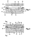
- the device 10 shown on the Figures 1 and 2 comprises a mold body 12, which is a lower half-mold, or die.
- This mold body 12 is made of an electrically conductive material, a part 14 of which constitutes a heating zone, or molding zone.
- an upper body 20 made of an electrically conductive material and devoid of molding zone.
- the upper body 20 is movable relative to the matrix along a vertical axis perpendicular to the joint plane of the mold.
- the primary function of the upper body 20 is to serve as an electroconductive filler to form an air gap between the die 12 and the upper body: it has no function directly related to the molding phase of a material. Thus, it is never directly in contact with the material to be molded, does not exert any force on it, and, unlike the matrix 12, does not have a molding or heating zone.
- a flexible waterproof membrane 42 such as a "vacuum cover”, intended for putting a material to be transformed 44 under pressure, in order to press it against the surface 16 of the molding zone 14.
- Each inductor 30 comprises a conductive coil and comprises two separable parts 32, 34, the lower portion 34 is secured to the matrix 12, while the upper portion 32 is integral with the upper body 20.
- the figure 1 shows the matrix 12 and the upper body 20 before operation, remote from each other to allow the establishment of the material to be transformed.
- the upper body 20 After placing a material 44, as shown in FIG. figure 2 the upper body 20 is moved to the die 12 so as to define an air gap of appropriate dimensions.
- electrically insulating shims 24 (and therefore transparent to the electromagnetic field) between the upper body 20 and the matrix 12.
- These shims constitute a reference stop for the upper body 20 (which must not abut or come into contact with the material 44), while ensuring the electrical insulation between the latter and the matrix 12 which is necessary for the operation of the device.
- the desired air gap height is obtained by virtue of the appropriate height of the wedges 24.
- the wedges 24 also provide sealing between the flexible membrane 42 and the matrix 12. They can in this case take the form of a frame circumscribing the perimeter of the molding area. This frame can be made of any suitable material, for example ceramic, thermosetting, thermoplastic, silicone, etc.
- the deformable pressure means which will be made of an electrically insulating material, the molding zone does not require any particular precaution, even in the case of the transformation of electrically conductive material parts (for example those containing carbon fibers.)
- seals 25 bearing on either side of the wedges 24, as shown on the figure 6 .
- sealing can be provided by the membrane 42 itself without the need for additional seals.
- the material 44 is clamped and held under pressure against the surface 16 of the molding zone 14 of the matrix by the membrane 42, in which the vacuum is evacuated by means of a vacuum pump (not shown), the matrix comprising in this purpose a network of suction channels 17 (visible on the figure 6 ).
- the upper body 20, not transparent to the electromagnetic field, allows the space delimited by the facing surfaces of the matrix 12 and the body 20 constitutes an air gap 40, thus confining the circulation of a magnetic field in this space.
- the inductive means comprising conductive turns 30 are traversed by alternating electric currents of frequency F, for example between 10 and 100 kilohertz, the inductors generate a magnetic field which envelopes the matrix 12 and the body 20.
- the magnetic field thus generated passes through these two bodies, and also circulates in the air gap, that is to say between the matrix 12 and the upper body 20.
- the magnetic field induces currents of direction opposite to the directions of the currents li, and the presence of the air gap makes it possible to generate induced currents Ic 1 and Ic 2 which respectively flow on the surface of the matrix and of the body 20.
- These induced currents Ic 1 and Ic 2 thus have a thermal action exclusively on the surface of these two bodies.
- the device according to the invention is all the more effective as the presence of the gap 40 has the effect of concentrating the magnetic flux within it, which further increases the action of the magnetic field at the molding zones, and therefore the inductive energy brought to the surface of the molding zones.
- the surface of the molding zone 14 can therefore be rapidly and locally heated directly at the molding zone / material interface, and not in the thickness of the mold body, which represents a considerable saving in energy, while at the same time achieving adequate pressurization of the part thanks to the flexible membrane.
- the air gap also has the effect of limiting the influence of the geometry and / or the distribution of the inductors on the resulting heating because the gap 40 has the effect of distributing uniformly the energy provided by the inductors.
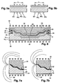
- inductive turns 30 ' 1 to 30' 4 ( Fig. 5b ) irregularly distributed over a length L around the mold have almost the same effect that the same number of inductive turns 30 1 to 30 4 ( Fig. 5a ) regularly distributed on the same length.
- This arrangement allows to choose at will the distribution of inductive turns.
- a conventional configuration with a coil inductor and an electroconductive without gap produces an unequal energy distribution, the injected energy having a maximum at the right of each inductive coil.
- the inductive turns surround the mold, and this can be equipped with a certain number of protruding elements, such as rising wedges, ejectors, etc.
- the presence of the gap also makes it possible to regulate and control very finely this temperature. It is thus possible to control very precisely the rate of rise in temperature (in ° C / min.), which is necessary for certain materials which require to respect constant rates of rise in temperature.
- the device according to the invention also has the advantage of reducing the costs of designing and manufacturing a mold.
- the upper body 20 may be designed in a single piece, obtained for example by molding or forging, and does not require a particular surface condition, and therefore expensive machining, unlike the matrix 12 and more particularly to the molding zone 14.
- it is not intended to apply pressure on the material to be processed, which imposes almost no constraint on the mechanical strength of the body 20 and leaves a great freedom in the choice materials.
- the body 20 will also be of a small thickness compared to the matrix 12, which again reduces the manufacturing cost of the body 20 and more generally of the device according to the invention.
- Another advantage of the invention lies in the fact that, since the body 20 is not intended to be in direct contact, to heat, or to exert forces with / on the material to be transformed, great freedom is maintained in the defining its shape: since the body 20 does not act as a counter-mold, the shape of its surface 22 facing the molding zone 14 may be independent of the shape of the molding zone ( and so of the piece final). This freedom in defining the shape of this surface 22 allows for example to modulate very finely the heating obtained by playing on the inductive and resistive phenomena. One can, in particular, play on the height of the gap to limit under heating or overheating.
- figure 7b locally decrease the height of the air gap, that is to say that at the location concerned the upper body 20 will be closer to the matrix 12 than other places, avoids under-heating local at the level of the matrix, the reduction of the gap to increase the concentration of the magnetic flux passing through the gap at this location, and therefore its effect.
- FIGs 7a and 7b the circulation of the magnetic field generated by the inductors 30, in particular inside the gap 40.
- figure 7a shows an air gap 40 of constant thickness and it can be seen that when it is not rectilinear, the flux lines are more concentrated inside the curve described by the air gap than outside, because the magnetic flux takes the path of least reluctance.
- the figure 7b shows an air gap 42 of non-constant thickness, in particular of modified thickness where the gap describes a curve. As the case may be, an increase or decrease in this thickness makes it possible to correct the non-homogeneous distribution of the magnetic flux found at the figure 7a .
- the non-magnetic material used to form the body 20 preferably has a low electrical resistivity, such as copper or aluminum. This makes it possible to avoid the energy losses as much as possible. Indeed, the body 20 being electrically conductive, it is traversed by currents induced by the magnetic field, but almost all of the energy generated by the inductors is injected into the matrix. For example, if the body 20 is aluminum, the energy it receives represents about 5% of the energy injected into the matrix 12.
- the molding zone 14 comprises a magnetic material possibly having a Curie point, while the remainder of the matrix 12 comprises a non-magnetic or slightly magnetic compound.
- the magnetic material constituting the molding zone 14 preferably has greater electrical resistivity than that of copper, such as, for example, nickel-based steel alloys, of chromium and / or titanium.
- a significant electrical resistivity of the molding zone is an advantage because it allows more efficient induction heating.
- the magnetic permeability of the material also influences the efficiency of induction heating.
- the remainder of the matrix 12 comprises a material achieving a good compromise between mechanical characteristics and magnetic and electrical properties.
- the material constituting the matrix 12 must be as little magnetic and resistive as possible, while presenting the mechanical strength necessary for the large and repeated efforts of the molding phases.
- stainless steel and copper represent an interesting compromise.
- the matrix can be made according to the method described in international application no. 2007/031660 the matrix 12, as well as the molding zone 14, consisting entirely of a magnetic material, the faces thereof facing the inductor means being covered with a layer 12 1 of shielding of a non-magnetic material such as copper, with the exception of the surface 16 of the molding zone 14.
- the shielding is such that its thickness is greater than the depth of penetration of the electromagnetic field.
- the material constituting the molding zone 14 has a Curie point, at a temperature close to this Curie point, the material loses its magnetic properties and induction heating decreases sharply, which is one of the possibilities for regulating the heating temperature. around the Curie point.
- the device represented on the Figures 1 and 2 is provided with a cooling system to allow the production or processing of parts by heating at high rate, the cooling being implemented between two treatments.
- a cooling system to allow the production or processing of parts by heating at high rate, the cooling being implemented between two treatments.
- the cooling thus obtained is very efficient, firstly because the metal mold body is thermally highly conductive, and secondly because the channels can be arranged closer to the surface 16 of the molding zone 14. therefore a very efficient cooling because fast and homogeneous throughout the room.
- This last feature is of crucial importance for certain materials such as polyester, for which stress relaxation problems arise during cooling if the part is not kept in shape during the entire cooling period (twisted piece, etc.).
- a complete production step called a shaping step, requiring, for example, a holding frame, an oven for a controlled temperature descent, etc. is eliminated.
- the upper body 20 is preferably also provided with a network of cooling channels 19, but this network is intended primarily to cool the upper body 20 when it heats up as cycles. In practice, the temperature rise of the upper body 20 will be rather slow and it will be possible to implement the cooling periodically, after a certain number of heating cycles.
- the inductors 30 are in two parts 32, 34 separable and secured respectively to the die 12 and the upper body 20, which allows rapid extraction of the workpiece 44 after molding, and therefore contributes to a high rate of manufacture.
- the electrical continuity between the two parts 32, 34 of the inductor network is ensured by electric contactors 36.
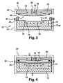
- the figure 3 represents a variant of the invention, in which the flexible membrane is secured to the upper body 20 and no longer to the matrix 12.
- the flexible membrane is pressed against the matrix and the part to be transformed by overpressure is ie by inflation.
- the membrane is for this purpose elastic and able to withstand high pressures, for example between 1 and 15 bar, thus making it possible to apply significant forces to the workpiece without requiring the use of significant mechanical means (press, etc.)
- Inflatable balloons can also be used which have a shape adapted to the molding zone in the case of very complex shapes.
- the upper body 20 has channels 26 for communicating the space between the membrane 46 and the surface 22 of the body 20 with a pressure source (not shown).
- the pressure source can generate a flow of air at the desired pressure inside the membrane.
- the membrane for example, for this purpose, it is possible to create an inlet channel and an air outlet channel, the latter being equipped with a pressure limiter calibrated at the desired minimum pressure, while the pressure source supplies an air to a significantly higher pressure.
- the membrane 46 it is possible to use, for example, materials such as silicone, or thermoplastics bearing a relative deformation of 100% or more.
- the material used will have to withstand temperatures of the order of 300 ° C.
- an array of inlet channels 17 1 of the resin may be provided, as shown in FIG. figure 6 , the suction channel network 17 also serving in this case to evacuate the resin.
- the resin inlet and outlet channels will be arranged to promote optimum resin filling and distribution. In the example of the figure 6 these are located on opposite sides of the die 12.
- two compaction means in combination: an inflatable membrane disposed on the upper body 20 with a vacuum membrane disposed on the matrix 12.
- Such a configuration will be particularly useful for controlling the level of porosity of the finished part . Indeed, evacuating under the vacuum membrane before exerting significant pressure with the inflatable membrane, we can exert significant effort on the part while preventing air from entering it.
- a single membrane made of a single material or comprising at least two layers of two different materials, this single membrane being subjected to both a depression and an overpressure.
- provision may be made to fix the vacuum membrane 42 on the upper body 20.
- the introduction and the removal of the membrane 42 are simplified, its displacement being linked to that of the body 20.
Landscapes
- Engineering & Computer Science (AREA)
- Mechanical Engineering (AREA)
- Health & Medical Sciences (AREA)
- Toxicology (AREA)
- Chemical & Material Sciences (AREA)
- Composite Materials (AREA)
- Moulds For Moulding Plastics Or The Like (AREA)
- General Induction Heating (AREA)
- Heating, Cooling, Or Curing Plastics Or The Like In General (AREA)
- Blow-Moulding Or Thermoforming Of Plastics Or The Like (AREA)
Description
- La présente invention concerne un dispositif et un procédé utilisant un chauffage par induction et des moyens de pression déformables, notamment dans le but de réaliser la transformation ou le moulage de matériaux, en particulier de matériaux composites à matrice thermoplastique ou thermodurcissable.
- Il est connu un dispositif, tel que celui décrit dans la demande internationale n°
WO2005/094127 , qui permet de localiser le chauffage par induction en surface, de manière à délimiter le chauffage à l'interface moule/matière. - Un tel dispositif comprend des inducteurs entourant deux corps de moule, réalisés en un matériau électriquement conducteur et comportant une zone chauffante destinée à être à proximité de, ou en contact avec le matériau à transformer, les corps de moule étant isolés électriquement l'un par rapport à l'autre. Ainsi, grâce à cette coupure électrique entre les deux corps de moule, les faces eh regard de ces derniers délimitent un entrefer dans lequel circule le champ magnétique créé par les inducteurs. Le champ magnétique induit alors des courants électriques en surface des corps de moule, et en particulier à la surface de la zone chauffante de chaque corps de moule, permettant ainsi de localiser le chauffage en surface.
- Un tel dispositif permet une montée en température des zones chauffantes très rapide et très importante, étant donné que l'énergie générée par les inducteurs est injectée directement à la surface des zones chauffantes, dans une épaisseur très faible, typiquement quelques dixièmes de millimètre. Il nécessite cependant la fabrication de deux demi-moules répondant à des contraintes mécaniques et d'usinage strictes. Bien que performant, un tel dispositif s'avère donc coûteux.
- D'autre part, un tel dispositif présente des performances limitées lorsque l'on souhaite réaliser des pièces géométriquement complexes, notamment celles présentant des formes non développables, et en particulier lorsque celles-ci présentent des surfaces perpendiculaires au plant de joint du moule, ou avec une faible dépouille. En effet, la pièce subit la pression exercée par le demi-moule supérieur (ou poinçon) sur le demi-moule inférieur (ou matrice). Pour cela, la zone moulante du poinçon présente une forme complémentaire de la zone moulante de la matrice, et le poinçon est mobile selon un axe perpendiculaire au plan de joint. Ce mouvement de translation permet d'exercer sur la pièce la pression requise pour les surfaces sensiblement parallèles au plan de joint du moule (i.e. perpendiculaires à la direction de déplacement du poinçon) ou faiblement inclinées par rapport à ce plan. En revanche, en raison de ce mouvement de translation unique, pour les surfaces verticales (i.e perpendiculaires au plan de joint) ou présentant un angle de dépouille faible, le poinçon n'est pas à même d'exercer une pression suffisante pour venir plaquer correctement la pièce sur la zone moulante de la matrice. Cela engendre donc des problèmes de qualité finale de la pièce réalisée (état de surface, résistance mécanique, imprégnation des fibres...)
- La présente invention a pour but de pallier les inconvénients de l'art antérieur en proposant un dispositif de chauffage de matériau(x) permettant une montée en température très rapide et contrôlable avec une très grande précision, et permettant de réaliser des pièces géométriquement complexes avec la qualité requise. Ainsi, l'invention concerne un dispositif utilisant un chauffage par induction couplé à un entrefer et équipé de moyens de pression déformables.
- Plus précisément, l'invention concerne un dispositif de chauffage pour la transformation d'un matériau selon la revendication 1 .,
- Ainsi, l'invention permet de limiter le chauffage par induction à une surface, afin de localiser le chauffage à l'interface moule/matière, ce qui permet de limiter la consommation d'énergie, et donc d'améliorer le rendement énergétique du dispositif, tout en assurant une pression uniformément répartie sur la pièce. En effet, les moyens de pression, ou de compactage, déformables, assurent une pression isobare sur la pièce indépendamment de la forme de la pièce. La productivité est également augmentée par rapport aux dispositifs connus utilisant des moyens de pression déformables, grâce à des temps de chauffe et de refroidissement diminués, une fraction très faible du volume du moule est soumise au chauffage par induction.
- Dans une réalisation, les moyens de pression comprennent une membrane souple.
- Dans une réalisation, la membrane souple est liée de manière étanche à la matrice, des moyens permettant de générer une dépression entre la membrane et la matrice.
- Dans une réalisation, la membrane souple est liée de manière étanche au corps supérieur, des moyens permettant de générer une surpression entre la membrane et le corps supérieur.
- Dans une réalisation, le dispositif comprend des moyens pour générer une dépression entre la membrane et la matrice et des moyens pour
- Dans une réalisation, la membrane souple est liée de manière étanche au corps supérieur, des moyens permettant de générer une surpression entre la membrane et le corps supérieur.
- Dans une réalisation, le dispositif comprend des moyens pour générer une dépression entre la membrane et la matrice et des moyens pour générer une surpression entre la membrane et le corps supérieur, ces moyens étant aptes à être actionnés simultanément ou successivement.
- Dans une réalisation, le dispositif comprend deux membranes souples, la première étant une membrane à dépression, la deuxième étant une membrane à surpression.
- Dans une réalisation, les moyens de pression sont solidaires du corps supérieur.
- Dans une réalisation, les moyens de pression sont solidaires de la matrice.
- Dans une réalisation, la zone moulante comprend un composé magnétique, de préférence de perméabilité magnétique relative et de résistivité électrique élevées, par exemple un acier à base de nickel, de chrome et/ou de titane.
- Dans une réalisation, le reste de la matrice comprend un matériau différent de celui constituant la zone moulante, notamment une matériau amagnétique ou peu magnétique, par exemple un acier inoxydable.
- Dans une réalisation, la matrice comprend un matériau magnétique, ses faces situées en regard des moyens inducteurs, à l'exception de la surface de la zone moulante, étant recouvertes d'une couche de blindage d'un matériau amagnétique empêchant la pénétration du champ magnétique dans la matrice.
- Dans une réalisation, le corps supérieur comprend un matériau amagnétique, de préférence de faible résistivité électrique, tel que de l'aluminium.
- Dans une réalisation, la zone moulante comprend un réseau de canaux de refroidissement.
- Dans une réalisation, le corps supérieur comprend un réseau de canaux de refroidissement.
- Dans une réalisation, la fréquence F du champ magnétique généré par les moyens inducteurs est au moins égale à 10 kHz et de préférence au plus égale à 100 kHz.
- Dans une réalisation, les moyens inducteurs comprennent deux parties séparables, respectivement solidaires de la matrice et du corps supérieur.
- Enfin, l'invention concerne également un procédé de fabrication d'une pièce mettant en oeuvre un dispositif tel que défini ci-dessus.
- D'autres caractéristiques et avantages de l'invention apparaîtront avec la description faite ci-dessous, cette dernière étant effectuée à titre d'exemple non limitatif en faisant référence aux dessins ci-après sur lesquels:
- les
figures 1 et 2 représentent un dispositif selon l'invention ; - les
figures 3 et 4 représentent une variante du dispositif précédent ; - les
figures 5a et 5b montrent deux dispositions différentes des inducteurs pour le dispositif de lafigure 2 , ces vues correspondant à des coupes simplifiées selon la ligne AA de lafigure 2 ; - La
figure 6 représente une vue en coupe d'une variante du dispositif de lafigure 1 , la coupe étant réalisée selon une direction analogue auxfigures 5a et 5B ; - Les
figures 7a et 7b représentent un détail du dispositif de lafigure 6 , respectivement dans deux configurations différentes. - Le dispositif 10 représenté sur les
figures 1 et 2 comporte un corps de moule 12, qui est un demi-moule inférieur, ou matrice. Ce corps de moule 12 est réalisé en un matériau électriquement conducteur, dont une partie 14 constitue une zone chauffante, ou zone moulante. En regard de la zone moulante 14, est disposé un corps supérieur 20 réalisé en un matériau électriquement conducteur et dépourvu de zone moulante. Le corps supérieur 20 est mobile par rapport à la matrice selon un axe vertical, perpendiculaire au plan de joint du moule. La fonction première du corps supérieur 20 est de servir de charge électroconductrice afin de former un entrefer entre la matrice 12 et le corps supérieur : il n'a aucune fonction directement liée à la phase de moulage d'un matériau. Ainsi, il n'est jamais directement en contact avec le matériau à mouler, n'exerce pas d'effort sur celui-ci, et, à la différence de la matrice 12, ne présente pas de zone moulante ou chauffante. - Entre la matrice 12 et le corps supérieur 20 est disposée une membrane étanche et souple 42, telle qu'une « bâche à vide », destinée à mettre un matériau à transformer 44 sous pression, afin de le plaquer contre la surface 16 de la zone moulante 14.
- Un réseau d'inducteurs 30, électriquement reliés en parallèle ou en série et connectés à un générateur de courant, est disposé autour de l'ensemble formé par la matrice 12 et le corps supérieur 20. Chaque inducteur 30 comporte une spire conductrice et comprend deux parties 32, 34 séparables, La partie inférieure 34 est solidaire de la matrice 12, tandis que la partie supérieure 32 est solidaire du corps supérieur 20.
- La
figure 1 montre la matrice 12 et le corps supérieur 20 avant opération, éloignés l'un de l'autre pour permettre la mise en place du matériau à transformer. - Après la mise en place d'un matériau 44, comme représenté sur la
figure 2 , le corps supérieur 20 est déplacé vers la matrice 12 de manière à délimiter un entrefer de dimensions appropriées. Dans l'exemple, on prévoit à cette fin des cales 24 électriquement isolantes (et donc transparentes au champ électromagnétique) entre le corps supérieur 20 et la matrice 12. Ces cales constituent une butée de référence pour le corps supérieur 20 (qui ne doit pas s'appuyer ou rentrer en contact avec le matériau 44), tout en assurant l'isolation électrique entre ce dernier et la matrice 12 qui est nécessaire au fonctionnement du dispositif. Ainsi la hauteur d'entrefer voulue est obtenue grâce à la hauteur appropriée des cales 24. On peut cependant envisager à la place toute solution alternative, par exemple un contact direct entre le corps supérieur et la matrice, l'un des deux étant revêtu d'un isolant électrique. Dans une variante, les cales 24 permettent également d'assurer l'étanchéité entre la membrane souple 42 et la matrice 12. Elles peuvent dans ce cas prendre la forme d'un cadre circonscrivant le périmètre de la zone de moulage. On pourra réaliser ce cadre dans tout matériau approprié, par exemple en céramique, thermodurcissable, thermoplastique, silicone, etc. En revanche, grâce à la présence des moyens de pression déformables qui seront réalisés dans un matériau électriquement isolant, la zone de moulage ne nécessite pas de précaution particulière, même dans le cas de la transformation de pièces en matériau électriquement conducteur (par exemple celles contenant des fibres de carbone.) Dans le cas où les cales 24 n'assurent pas l'étanchéité entre la matrice 12 et le corps supérieur 20, on prévoit des joints 25 s'appuyant de part et d'autre des cales 24, comme montré sur lafigure 6 . Dans une variante, l'étanchéité peut être assurée par la membrane 42 elle-même sans qu'il soit nécessaire de prévoir de joints supplémentaires. - Lors de la phase de transformation, comme montré sur la
figure 2 , le matériau 44 est enserré et maintenu sous pression contre la surface 16 de la zone moulante 14 de la matrice par la membrane 42, dans laquelle on fait le vide au moyen d'une pompe à vide (non représentée), la matrice comprenant dans ce but un réseau de canaux d'aspiration 17 (visible sur lafigure 6 ). Le corps supérieur 20, non transparent au champ électromagnétique, permet que l'espace délimité par les surfaces en regard de la matrice 12 et du corps 20 constitue un entrefer 40, confinant ainsi la circulation d'un champ magnétique dans cet espace. Ainsi, lorsque les moyens inducteurs comprenant des spires conductrices 30 sont parcourus par des courants électriques li alternatifs de fréquence F, par exemple comprise entre 10 et 100 kilohertz, les inducteurs génèrent un champ magnétique qui enveloppe la matrice 12 et le corps 20. - Le champ magnétique ainsi généré traverse ces deux corps, et circule également dans l'entrefer, c'est-à-dire entre la matrice 12 et le corps supérieur 20. Le champ magnétique induit des courants de sens opposé aux sens des courants li, et la présence de l'entrefer permet de générer des courants induits Ic1 et Ic2 qui circulent respectivement à la surface de la matrice et du corps 20. Ces courants induits Ic1 et Ic2 ont donc une action thermique exclusivement à la surface de ces deux corps.
- Le dispositif selon l'invention est d'autant plus efficace que la présence de l'entrefer 40 a pour effet de concentrer le flux magnétique en son sein, ce qui augmente encore l'action du champ magnétique au niveau des zones moulantes, et donc l'énergie inductive apportée à la surface des zones moulantes. On peut donc chauffer rapidement et localement la surface de la zone moulante 14, directement à l'interface zone moulante/matériau, et non dans l'épaisseur du corps de moule, ce qui représente une économie d'énergie importante, tout en réalisant une mise en pression adéquate de la pièce grâce à la membrane souple.
- L'entrefer a également pour effet de limiter l'influence de la géométrie et/ou de la répartition des inducteurs sur le chauffage résultant car l'entrefer 40 a pour effet de répartir uniformément l'énergie apportée par les inducteurs. Ainsi des spires inductrices 30'1 à 30'4 (
fig. 5b ) réparties irrégulièrement sur une longueur L autour du moule ont pratiquement le même effet que le même nombre de spires inductrices 301 à 304 (fig. 5a ) réparties régulièrement sur la même longueur. Cette disposition permet de choisir à volonté la répartition des spires inductrices. On rappelle qu'à l'opposé, une configuration classique avec un inducteur à spires et une charge électroconductrice sans entrefer, produit une répartition énergétique inégale, l'énergie injectée présentant un maximum au droit de chaque spire inductive. Cette possibilité d'avoir une répartition inégale des spires d'inducteurs s'avère particulièrement avantageuse car, dans le dispositif objet de l'invention, les spires inductrices entourent le moule, et celui-ci peut être équipé d'un certain nombre d'éléments dépassants, tels que des cales montantes, des éjecteurs, etc. - Outre une répartition idéale de l'énergie injectée, offrant donc une température uniforme à la surface de la zone moulante, la présence de l'entrefer permet également de réguler et piloter très finement cette température. Il est ainsi possible de contrôler très précisément la vitesse de montée en température (en °C/min.), ce qui est nécessaire pour certains matériaux qui nécessitent de respecter des vitesses de montée en température constantes.
- Le dispositif selon l'invention présente également l'avantage de diminuer les coûts de conception et de fabrication d'un moule. En effet, le corps supérieur 20 peut être conçu en une pièce monobloc, obtenue par exemple par moulage ou forgeage, et ne nécessite pas d'état de surface particulier, et donc d'usinages coûteux, contrairement à la matrice 12 et plus particulièrement à la zone moulante 14. De plus, celui-ci n'est pas destiné à appliquer de pression sur le matériau à transformer, ce qui n'impose quasiment aucune contrainte quant à la résistance mécanique du corps 20 et laisse une grande liberté dans le choix des matériaux. Dans certains cas, le corps 20 sera en outre d'une épaisseur faible comparée à la matrice 12, ce qui réduit là encore le coût de fabrication du corps 20 et plus généralement du dispositif selon l'invention.
- Un autre avantage de l'invention réside dans le fait que, le corps 20 n'étant pas destiné à être en contact directement, à chauffer, ou à exercer des efforts avec/sur le matériau à transformer, on garde une grande liberté dans la définition de sa forme : comme le corps 20 ne joue pas le rôle d'un contre-moule, la forme de sa surface 22 située en vis-à-vis de la zone moulante 14 peut être indépendante de la forme de la zone moulante (et donc de la pièce finale). Cette liberté dans la définition de la forme de cette surface 22 permet par exemple de moduler très finement la chauffe obtenue en jouant sur les phénomènes inductifs et résistifs. On peut, notamment, jouer sur la hauteur de l'entrefer pour limiter des sous chauffes ou des surchauffes. Par exemple, comme montré sur la
figure 7b , diminuer localement la hauteur de l'entrefer, c'est-à-dire qu'à l'endroit concerné le corps supérieur 20 sera plus proche de la matrice 12 qu'à d'autres endroits, permet d'éviter une sous chauffe locale au niveau de la matrice, la réduction de l'entrefer permettant d'augmenter la concentration du flux magnétique traversant l'entrefer à cet endroit, et donc son effet. On peut ainsi voir, sur lesfigures 7a et 7b , la circulation du champ magnétique généré par les inducteurs 30, en particulier à l'intérieur de l'entrefer 40. Lafigure 7a montre un entrefer 40 d'épaisseur constante et l'on voit que lorsque celui-ci n'est pas rectiligne, les lignes de flux sont plus concentrées à l'intérieur de la courbe décrite par l'entrefer qu'à l'extérieur, du fait que le flux magnétique emprunte le chemin de moindre reluctance. Il se produit donc des surchauffes et des sous-chauffes à ces endroits courbes, respectivement à l'intérieur et à l'extérieur de la courbe. Lafigure 7b montre un entrefer 42 d'épaisseur non constante, en particulier d'épaisseur modifiée aux endroits où l'entrefer décrit une courbe. Selon les cas, une augmentation ou une diminution de cette épaisseur permet de corriger la répartition non homogène du flux magnétique constaté à lafigure 7a . - Le matériau amagnétique utilisé pour constituer le corps 20 a, de préférence, une faible résistivité électrique, comme par exemple le cuivre ou l'aluminium. Cela permet d'éviter au maximum les pertes énergétiques. En effet, le corps 20 étant électriquement conducteur, il est parcouru par des courants induits par le champ magnétique, mais la quasi-totalité de l'énergie générée par les inducteurs est injectée dans la matrice. Par exemple, si le corps 20 est en aluminium, l'énergie qu'il reçoit représente environ 5% de l'énergie injectée dans la matrice 12.
- Afin de minimiser les pertes d'énergie dans la matrice 12, la zone moulante 14 comprend un matériau magnétique présentant éventuellement un point de Curie, tandis que le reste de la matrice 12 comprend un composé amagnétique ou peu magnétique. Le matériau magnétique constituant la zone moulante 14 présente de préférence une résistivité électrique plus importante que celle du cuivre, comme par exemple des alliages d'acier à base de nickel, de chrome et/ou de titane. Une résistivité électrique importante de la zone moulante constitue un avantage car elle permet un chauffage par induction plus efficace. Cependant, il est à noter que la perméabilité magnétique du matériau influe également sur le rendement du chauffage par induction. Le reste de la matrice 12 comprend un matériau réalisant un bon compromis entre caractéristiques mécaniques et propriétés magnétiques et électriques. En effet, afin de limiter les pertes énergétiques et de concentrer toute l'action du chauffage au niveau de la surface 16 de la zone moulante 14, le matériau constituant la matrice 12 doit être aussi peu magnétique et résistif que possible, tout en présentant la résistance mécanique nécessaire aux efforts importants et répétés des phases de moulage. A ce titre, l'acier inoxydable et le cuivre représentent un compromis intéressant.
- Dans une variante représentée à la
figure 6 , la matrice pourra être réalisée selon la méthode décrite dans la demande internationale n°2007/031660 , la matrice 12, ainsi que la zone moulante 14, étant constituée intégralement d'un matériau magnétique, les faces de celle-ci situées en regard des moyens inducteurs étant recouvertes d'une couche 121 de blindage en un matériau amagnétique tel que du cuivre, à l'exception de la surface 16 de la zone moulante 14. Dans cette configuration, le blindage est tel que son épaisseur est supérieure à la profondeur de pénétration du champ électromagnétique. Ainsi, les courants induits circulent dans la couche de blindage, provoquant peu d'échauffement et peu de pertes énergétiques, sauf à l'endroit de la surface de la zone moulante, où le matériau est très réactif au chauffage par induction. - Lorsque le matériau constituant la zone moulante 14 présente un point de Curie, à une température proche de ce point de Curie, le matériau perd ses propriétés magnétiques et le chauffage par induction diminue fortement, ce qui est une des possibilités pour réguler la température de chauffage autour du point de Curie.
- Le dispositif représenté sur les
figures 1 et 2 est pourvu d'un système de refroidissement pour permettre la réalisation ou la transformation de pièces par chauffage à cadence élevée, le refroidissement étant mis en oeuvre entre deux traitements. A cet effet, on prévoit dans la matrice 12 de la zone moulante 12, un réseau de canaux 18 permettant de faire circuler un liquide de refroidissement à proximité des surfaces moulantes. Le refroidissement ainsi obtenu est très performant, d'une part parce que le corps de moule métallique est thermiquement très conducteur, et d'autre part parce que les canaux peuvent être disposés au plus près de la surface 16 de la zone moulante 14. On réalise donc un refroidissement très performant car rapide et homogène sur l'ensemble de la pièce. Cette dernière particularité revêt une importance cruciale pour certains matériaux tels que le polyester, pour lesquels des problèmes de relâchement de contraintes se posent lors du refroidissement si la pièce n'est pas maintenue en forme pendant tout le temps du refroidissement (pièce vrillée, etc.) On supprime donc pour certains matériaux une étape entière de production, dite étape de conformage, nécessitant par exemple un châssis de maintien, une étuve pour une descente en température contrôlée, etc. - Le corps supérieur 20 est de préférence également pourvu d'un réseau de canaux de refroidissement 19, mais ce réseau est destiné principalement à refroidir le corps supérieur 20 lorsque celui-ci s'échauffe au fur et à mesure des cycles. En pratique, l'élévation de température du corps supérieur 20 sera plutôt lente et on pourra mettre en oeuvre le refroidissement en oeuvre périodiquement, après un certain nombre de cycles de chauffage.
- Les inducteurs 30 sont en deux parties 32, 34 séparables et solidaires respectivement de la matrice 12 et du corps supérieur 20, ce qui permet une extraction rapide de la pièce 44 après moulage, et contribue donc à une fabrication à cadence élevée. Lors de la transformation d'un matériau, la continuité électrique entre les deux parties 32, 34 du réseau d'inducteurs est assurée par des contacteurs électriques 36.
- La
figure 3 représente une variante de l'invention, dans laquelle la membrane souple est solidaire du corps supérieur 20 et non plus de la matrice 12. Dans cette configuration, la membrane souple est plaquée contre la matrice et la pièce à transformer par surpression, c'est-à-dire par gonflage. La membrane est dans ce but élastique et à même de supporter des pressions importantes, par exemple comprise entre 1 et 15 bars, permettant ainsi d'appliquer des efforts importants sur la pièce à transformer sans nécessiter l'utilisation de moyens mécaniques importants (presse, etc.) On peut également employer des baudruches gonflables qui présentent une forme adaptée à la zone moulante dans le cas de formes très complexes. Dans cette configuration, le corps supérieur 20 présente des canaux 26 permettant de mettre en communication l'espace compris entre la membrane 46 et la surface 22 du corps 20 avec une source de pression (non représentée). Afin de favoriser un refroidissement rapide tout en maintenant une pression sur la pièce, on pourra envisager que la source de pression permette de générer une circulation d'air à la pression désirée à l'intérieur de la membrane. On pourra par exemple à cet effet réaliser un canal d'entrée et un canal de sortie de l'air, ce dernier étant équipé d'un limiteur de pression taré à la pression minimale désirée, tandis que la source de pression fournit un air à une pression significativement plus élevée. - Pour réaliser la membrane 46, on pourra utiliser par exemple des matériaux tels que le silicone, ou des thermoplastiques supportant une déformation relative de 100% ou plus. De préférence, le matériau utilisé devra supporter des températures de l'ordre de 300°C.
- Si l'on souhaite mettre en oeuvre des procédés avec transfert de résine, de type RTM, on pourra prévoir un réseau de canaux d'entrée 171 de la résine, comme montré sur la
figure 6 , le réseau de canaux d'aspiration 17 servant dans ce cas également à évacuer la résine. Les canaux d'entrée et de sortie de résine seront disposés de manière à favoriser un remplissage et une répartition de la résine optimaux. Dans l'exemple de lafigure 6 , ceux-ci sont situés sur des côtés opposés de la matrice 12. - Dans une variante, on pourra utiliser deux moyens de compactage en combinaison : une membrane gonflable disposée sur le corps supérieur 20 avec une membrane à dépression disposée sur la matrice 12. Une telle configuration sera notamment utile pour contrôler le niveau de porosité de la pièce finie. En effet, on faisant le vide sous la membrane à dépression avant d'exercer une pression importante avec la membrane gonflable, on pourra exercer des efforts importants sur la pièce tout en évitant que de l'air s'infiltre dans celle-ci. Dans ce même but, on pourra également utiliser une membrane unique, réalisée dans un matériau unique ou comprenant au moins deux couches de deux matériaux différents, cette membrane unique étant soumise à la fois à une dépression et à une surpression.
- Dans une variante, on pourra prévoir de fixer la membrane à dépression 42 sur le corps supérieur 20. Ainsi la mise en place et l'enlèvement de la membrane 42 sont simplifiés, son déplacement étant lié à celui du corps 20.
- De façon classique, des moyens mécaniques (non représentés) d'éjection de la pièce fabriquée sont également prévus.
Claims (17)
- Dispositif (10) de chauffage pour la transformation d'un matériau (44), comprenant :- un corps de moule inférieur (12), ou matrice, réalisé en un matériau électriquement conducteur et comportant une zone moulante (14) en matériau magnétique destinée à être en contact avec le matériau à transformer ;- un corps supérieur (20) dépourvu de zone moulante, réalisé en un matériau électriquement conducteur amagnétique de faible résistivité électrique ;- des moyens inducteurs (30) pour générer un champ magnétique enveloppant la matrice (12) et le corps supérieur (20) ;- des moyens de pression déformables (42, 46), disposés entre la matrice (12) et le corps supérieur (20), aptes à exercer une pression uniforme sur le matériau à transformer, pour le plaquer contre la zone moulante- caractérisé en ce qu'il comporte des cales (24) électriquement isolantes et transparentes au champ magnétique, disposées entre la matrice et le corps supérieur de manière à ménager un entrefer entre les faces en regard de ladite matrice et dudit corps supérieur, ledit entrefer étant maintenu pendant le chauffage et la transformation du matériau à transformer , le champ magnétique circulant dans l'entrefer induisant des courants à la surface de la zone moulante (14) de la matrice (12), permettant ainsi de localiser l'action des inducteurs à l'interface zone moulante/matériau à transformer
- Dispositif selon la revendication 1, dans lequel les cales isolantes (24) assurent en outre l'étanchéité entre les moyens de pression déformables d'une part, et, d'autre part, la matrice (12) et/ou le corps supérieur (20).
- Dispositif selon la revendication 1 ou 2, dans lequel les moyens de pression comprennent une membrane souple (42, 46).
- Dispositif selon la revendication 3, dans lequel la membrane souple (42) est liée de manière étanche à la matrice (12), des moyens permettant de générer une dépression entre la membrane (42) et la matrice (12).
- Dispositif selon la revendication 4, dans lequel la membrane souple (46) est liée de manière étanche au corps supérieur (20), des moyens permettant de générer une surpression entre la membrane (46) et le corps supérieur (20).
- Dispositif selon les revendications 4 et 5, comprenant des moyens pour générer une dépression entre la membrane (42, 46) et la matrice (12) et des moyens pour générer une surpression entre la membrane (42, 46) et le corps supérieur (20), ces moyens étant aptes à être actionnés simultanément ou successivement.
- Dispositif selon les revendications 4 et 5, comprenant deux membranes souples (42, 46), la première étant une membrane à dépression, la deuxième étant une membrane à surpression.
- Dispositif selon l'une des revendications 1 à 7, dans lequel les moyens de pression sont solidaires du corps supérieur (20).
- Dispositif selon l'une des revendications 1 à 8, dans lequel les moyens de pression sont solidaires de la matrice (12).
- Dispositif selon l'une des revendications précédentes, dans lequel la zone moulante (14) comprend un composé magnétique, de préférence de perméabilité magnétique relative et de résistivité électriques élevées, par exemple un acier à base de nickel, de chrome et/ou de titane.
- Dispositif selon la revendication 10, dans lequel le reste de la matrice (12) comprend un matériau différent de celui constituant la zone moulante (14), notamment un matériau amagnétique ou peu magnétique, par exemple un acier inoxydable.
- Dispositif selon l'une des revendications 1 à 10, dans lequel la matrice (12) comprend un matériau magnétique, ses faces situées en regard des moyens inducteurs, à l'exception de la surface (16) de la zone moulante (14), étant recouvertes d'une couche de blindage d'un matériau amagnétique empêchant la pénétration du champ magnétique dans la matrice (12).
- Dispositif selon l'une des revendications précédentes, dans lequel le corps supérieur (20) comprend un matériau amagnétique, de préférence de faible résistivité électrique, tel que de l'aluminium.
- Dispositif selon l'une des revendications précédentes, dans lequel la zone moulante (14) comprend un réseau de canaux (18) de refroidissement.
- Dispositif selon l'une des revendications précédentes, dans lequel le corps supérieur (20) comprend un réseau de canaux (19) de refroidissement.
- Dispositif selon une des revendications précédentes dans lequel la fréquence F du champ magnétique généré par les moyens inducteurs est au moins égale à 10 kHz et de préférence au plus égale à 100 kHz.
- Dispositif selon l'une des revendications précédentes, dans lequel les moyens inducteurs (30) comprennent deux parties séparables (32,34), respectivement solidaires de la matrice (12) et du corps supérieur (20).
Applications Claiming Priority (2)
| Application Number | Priority Date | Filing Date | Title |
|---|---|---|---|
| FR0851728A FR2928808B1 (fr) | 2008-03-17 | 2008-03-17 | Dispositif de transformation de materiaux utilisant un chauffage par induction et des moyens de compactage deformables |
| PCT/FR2009/000280 WO2009125079A2 (fr) | 2008-03-17 | 2009-03-17 | Dispositif de transformation de materiaux utilisant un chauffage par induction et des moyens de compactage deformables |
Publications (2)
| Publication Number | Publication Date |
|---|---|
| EP2255595A2 EP2255595A2 (fr) | 2010-12-01 |
| EP2255595B1 true EP2255595B1 (fr) | 2016-06-29 |
Family
ID=39865643
Family Applications (1)
| Application Number | Title | Priority Date | Filing Date |
|---|---|---|---|
| EP09729604.0A Not-in-force EP2255595B1 (fr) | 2008-03-17 | 2009-03-17 | Dispositif de transformation de materiaux utilisant un chauffage par induction et des moyens de compactage deformables |
Country Status (8)
| Country | Link |
|---|---|
| US (1) | US8794950B2 (fr) |
| EP (1) | EP2255595B1 (fr) |
| JP (1) | JP5450584B2 (fr) |
| CN (2) | CN106079171A (fr) |
| CA (1) | CA2718485C (fr) |
| ES (1) | ES2601360T3 (fr) |
| FR (1) | FR2928808B1 (fr) |
| WO (1) | WO2009125079A2 (fr) |
Cited By (1)
| Publication number | Priority date | Publication date | Assignee | Title |
|---|---|---|---|---|
| DE102021121225A1 (de) | 2021-08-16 | 2023-02-16 | Deutsches Zentrum für Luft- und Raumfahrt e.V. | Presswerkzeug |
Families Citing this family (27)
| Publication number | Priority date | Publication date | Assignee | Title |
|---|---|---|---|---|
| FR2973278B1 (fr) * | 2011-04-01 | 2014-09-12 | Roctool | Piece en materiau composite a matrice thermoplastique et renfort fibreux en fibres naturelles et procede d'obtention d'une telle piece |
| WO2011104442A1 (fr) * | 2010-02-23 | 2011-09-01 | Arcelormittal Investigación Y Desarrollo Sl | Moule, procédé de fabrication d'un moule et procédé de fabrication d'un produit en matière plastique ou composite au moyen de ce moule |
| CN103459130B (zh) * | 2011-04-01 | 2016-10-19 | 罗克器械公司 | 用于压缩-固结由具有尤其源于天然的连续纤维增强的热塑性基体的复合材料制成的零件的装置和方法 |
| JP5905959B2 (ja) * | 2011-06-28 | 2016-04-20 | テーセェーテク スウェーデン アクチエボラグTCTech Sweden AB | 成形型または金型を加熱する装置および方法 |
| JP5860294B2 (ja) * | 2012-01-31 | 2016-02-16 | 東洋紡株式会社 | 金型及び熱可塑性樹脂系繊維強化複合材料成形品の製造方法 |
| JP5833460B2 (ja) * | 2012-01-31 | 2015-12-16 | 東洋紡株式会社 | 金型及び熱可塑性樹脂系繊維強化複合材料成形品の製造方法 |
| EP2842724B1 (fr) * | 2013-08-29 | 2018-11-21 | Airbus Operations GmbH | Régulation de la température active pour chauffage par induction |
| BR112016002868A2 (pt) * | 2013-08-29 | 2017-08-01 | Dow Global Technologies Llc | método para produzir moldes não metálicos autoaquecíveis |
| DE102013018452B4 (de) | 2013-11-02 | 2020-09-10 | Vereinigung zur Förderung des Instituts für Kunststoffverarbeitung in Industrie und Handwerk an der Rhein.-Westf. Technischen Hochschule Aachen e.V. | Verfahren zur Herstellung eines aus mindestens einer Kunststoffkomponente und mindestens einer Metallkomponente bestehenden Verbundbauteils |
| FR3015918A1 (fr) * | 2013-12-31 | 2015-07-03 | Roctool | Dispositif pour le chauffage d’un moule |
| CN103962437B (zh) * | 2014-05-19 | 2016-04-20 | 华中科技大学 | 一种电磁力驱动的金属材料塑性成形方法 |
| CN106217904B (zh) * | 2016-07-20 | 2018-06-19 | 保定华翼风电叶片研究开发有限公司 | 一种挤压成型光面等厚玻璃钢测试平板的制备装置及方法 |
| US10464244B2 (en) * | 2017-02-15 | 2019-11-05 | Fca Us Llc | Injection mold for ultra thin wall components |
| US11225047B2 (en) | 2017-03-15 | 2022-01-18 | International Automotive Components Group North America, Inc. | Skin-foam-substrate structure via induction heating |
| FR3069479B1 (fr) * | 2017-07-25 | 2020-07-17 | Roctool | Procede et dispositif pour la fabrication d’une piece composite de forme complexe |
| US10814526B2 (en) | 2017-09-22 | 2020-10-27 | The Boeing Company | Induction forming and curing of thermoset composite charges |
| US11390013B2 (en) * | 2017-11-21 | 2022-07-19 | General Electric Company | Vacuum forming mold assembly and associated methods |
| US11008453B2 (en) | 2018-01-16 | 2021-05-18 | Arkema France | Polymeric composite articles comprising the heterogeneous surface/bulk distribution of discrete phase |
| EP3567147B1 (fr) * | 2018-05-09 | 2026-03-18 | Fabdesigns, Inc. | Procédé pour la réalisation d'une structure plate en polymères renforcée par fibres |
| IL278583B2 (en) | 2018-05-25 | 2024-07-01 | Philip Morris Products Sa | Susceptor assembly for aerosol generation comprising a susceptor tube |
| US11485096B2 (en) * | 2019-05-17 | 2022-11-01 | The Boeing Company | Method and system for manufacturing composite structures using a magnesium bladder |
| FR3105077B1 (fr) * | 2019-12-21 | 2023-02-24 | Roctool | Procédé et outillage pour la fabrication d’une coque quadrangulaire en matériau composite |
| FR3120008B1 (fr) * | 2021-02-22 | 2024-03-15 | Airbus Operations Sas | Dispositif de consolidation d’une pièce en matériau composite par chauffage par induction |
| CN114261048A (zh) * | 2021-12-28 | 2022-04-01 | 成都双高实业有限责任公司 | 一种用于聚三氟氯乙烯热成型的中频加热工艺及加热设备 |
| CN115157501B (zh) * | 2022-07-29 | 2023-05-16 | 太原理工大学 | 一种输送带接头硫化机用矩阵式电磁感应加热装置 |
| US12285888B2 (en) | 2023-01-11 | 2025-04-29 | Meggitt Aerospace Limited | Induction heated tooling and methods of using the same |
| FR3150135A1 (fr) | 2023-06-21 | 2024-12-27 | Commissariat A L’Energie Atomique Et Aux Energies Alternatives | Procédé de fabrication d’un module photovoltaïque par thermoformage d’un empilement multicouche |
Family Cites Families (9)
| Publication number | Priority date | Publication date | Assignee | Title |
|---|---|---|---|---|
| US5641422A (en) * | 1991-04-05 | 1997-06-24 | The Boeing Company | Thermoplastic welding of organic resin composites using a fixed coil induction heater |
| US5591369A (en) * | 1991-04-05 | 1997-01-07 | The Boeing Company | Method and apparatus for consolidating organic matrix composites using induction heating |
| AUPO071296A0 (en) * | 1996-07-01 | 1996-07-25 | Ayres, Patrick Michael William | Heating of components |
| JP3874511B2 (ja) * | 1996-12-03 | 2007-01-31 | 日世株式会社 | 澱粉製生分解性成形物の製造方法 |
| FR2816237B1 (fr) * | 2000-11-08 | 2003-09-19 | Roctool | Moules pour la transformation des matieres plastiques et composites et procede de transformation associe |
| US6979807B2 (en) * | 2003-08-13 | 2005-12-27 | The Boeing Company | Forming apparatus and method |
| FR2867939B1 (fr) * | 2004-03-18 | 2007-08-10 | Roctool | Procede pour chauffer des materiaux en vue de produire des objets et dispositif mettant en oeuvre de procede |
| FR2890588B1 (fr) | 2005-09-12 | 2007-11-16 | Roctool Soc Par Actions Simpli | Dispositif de transformation de materiaux utilisant un chauffage par induction |
| US8372327B2 (en) * | 2007-09-13 | 2013-02-12 | The Boeing Company | Method for resin transfer molding composite parts |
-
2008
- 2008-03-17 FR FR0851728A patent/FR2928808B1/fr not_active Expired - Fee Related
-
2009
- 2009-03-17 JP JP2011500252A patent/JP5450584B2/ja not_active Expired - Fee Related
- 2009-03-17 EP EP09729604.0A patent/EP2255595B1/fr not_active Not-in-force
- 2009-03-17 US US12/922,969 patent/US8794950B2/en not_active Expired - Fee Related
- 2009-03-17 CN CN201610498536.XA patent/CN106079171A/zh active Pending
- 2009-03-17 CA CA2718485A patent/CA2718485C/fr not_active Expired - Fee Related
- 2009-03-17 WO PCT/FR2009/000280 patent/WO2009125079A2/fr not_active Ceased
- 2009-03-17 ES ES09729604.0T patent/ES2601360T3/es active Active
- 2009-03-17 CN CN2009801092718A patent/CN102017790A/zh active Pending
Cited By (1)
| Publication number | Priority date | Publication date | Assignee | Title |
|---|---|---|---|---|
| DE102021121225A1 (de) | 2021-08-16 | 2023-02-16 | Deutsches Zentrum für Luft- und Raumfahrt e.V. | Presswerkzeug |
Also Published As
| Publication number | Publication date |
|---|---|
| US8794950B2 (en) | 2014-08-05 |
| WO2009125079A3 (fr) | 2009-11-26 |
| CA2718485C (fr) | 2016-11-01 |
| FR2928808B1 (fr) | 2012-04-20 |
| FR2928808A1 (fr) | 2009-09-18 |
| EP2255595A2 (fr) | 2010-12-01 |
| JP5450584B2 (ja) | 2014-03-26 |
| WO2009125079A2 (fr) | 2009-10-15 |
| CA2718485A1 (fr) | 2009-10-15 |
| CN102017790A (zh) | 2011-04-13 |
| CN106079171A (zh) | 2016-11-09 |
| US20110057357A1 (en) | 2011-03-10 |
| ES2601360T3 (es) | 2017-02-14 |
| JP2011514646A (ja) | 2011-05-06 |
Similar Documents
| Publication | Publication Date | Title |
|---|---|---|
| CA2718485C (fr) | Dispositif de transformation de materiaux utilisant un chauffage par induction et des moyens de compactage deformables | |
| EP1728411B1 (fr) | Procede pour chauffer des materiaux en vue de produire des objets et dispositif mettant en oeuvre ce procede | |
| EP2349667B1 (fr) | Dispositif de transformation de materiaux utilisant un chauffage par induction permettant un prechauffage du dispositif | |
| EP1924415B1 (fr) | Dispositif de transformation de materiaux utilisant un chauffage par induction | |
| EP2861399B1 (fr) | Procédé et dispositif pour le préchauffage d'un moule notamment de moulage par injection | |
| CA2945246C (fr) | Dispositif pour le chauffage d'un moule | |
| EP3119585B1 (fr) | Dispositif et procédé de soudage de pièces en matériau composite thermoplastique | |
| CA2612756C (fr) | Dispositif de chauffage par induction et procede de fabrication de pieces a l'aide d'un tel dispositif | |
| EP0499513B1 (fr) | Dispositif à conduction thermique variable, prévu pour être intercalé entre un plateau de chauffage et un plateau de refroidissement sur une machine telle qu'une presse | |
| EP2394492B1 (fr) | Membrane souple pour la realisation de pieces en materiaux composites | |
| EP3455044B1 (fr) | Dispositif et procédé pour le moulage et la consolidation d'une préforme textile | |
| WO2008142337A2 (fr) | Procede et dispositif de chauffage de pieces tubulaires ou pleines par induction | |
| EP3126126A1 (fr) | Procédé et installation de réalisation d'une pièce en matériau composite | |
| EP3700695B1 (fr) | Dispositif et méthode pour le moulage d'un alliage de verre métallique massif | |
| FR2994121A1 (fr) | Procede de fabrication d'un outillage de moulage destine au moulage d'une piece en materiau composite |
Legal Events
| Date | Code | Title | Description |
|---|---|---|---|
| PUAI | Public reference made under article 153(3) epc to a published international application that has entered the european phase |
Free format text: ORIGINAL CODE: 0009012 |
|
| 17P | Request for examination filed |
Effective date: 20100917 |
|
| AK | Designated contracting states |
Kind code of ref document: A2 Designated state(s): AT BE BG CH CY CZ DE DK EE ES FI FR GB GR HR HU IE IS IT LI LT LU LV MC MK MT NL NO PL PT RO SE SI SK TR |
|
| AX | Request for extension of the european patent |
Extension state: AL BA RS |
|
| DAX | Request for extension of the european patent (deleted) | ||
| 17Q | First examination report despatched |
Effective date: 20150401 |
|
| GRAP | Despatch of communication of intention to grant a patent |
Free format text: ORIGINAL CODE: EPIDOSNIGR1 |
|
| INTG | Intention to grant announced |
Effective date: 20160120 |
|
| RIN1 | Information on inventor provided before grant (corrected) |
Inventor name: FEIGENBLUM, JOSE Inventor name: GUICHARD, ALEXANDRE |
|
| GRAS | Grant fee paid |
Free format text: ORIGINAL CODE: EPIDOSNIGR3 |
|
| GRAA | (expected) grant |
Free format text: ORIGINAL CODE: 0009210 |
|
| AK | Designated contracting states |
Kind code of ref document: B1 Designated state(s): AT BE BG CH CY CZ DE DK EE ES FI FR GB GR HR HU IE IS IT LI LT LU LV MC MK MT NL NO PL PT RO SE SI SK TR |
|
| REG | Reference to a national code |
Ref country code: GB Ref legal event code: FG4D Free format text: NOT ENGLISH |
|
| REG | Reference to a national code |
Ref country code: CH Ref legal event code: EP |
|
| REG | Reference to a national code |
Ref country code: AT Ref legal event code: REF Ref document number: 809987 Country of ref document: AT Kind code of ref document: T Effective date: 20160715 |
|
| REG | Reference to a national code |
Ref country code: IE Ref legal event code: FG4D Free format text: LANGUAGE OF EP DOCUMENT: FRENCH |
|
| REG | Reference to a national code |
Ref country code: DE Ref legal event code: R096 Ref document number: 602009039451 Country of ref document: DE |
|
| REG | Reference to a national code |
Ref country code: NL Ref legal event code: FP |
|
| REG | Reference to a national code |
Ref country code: LT Ref legal event code: MG4D |
|
| PG25 | Lapsed in a contracting state [announced via postgrant information from national office to epo] |
Ref country code: LT Free format text: LAPSE BECAUSE OF FAILURE TO SUBMIT A TRANSLATION OF THE DESCRIPTION OR TO PAY THE FEE WITHIN THE PRESCRIBED TIME-LIMIT Effective date: 20160629 Ref country code: FI Free format text: LAPSE BECAUSE OF FAILURE TO SUBMIT A TRANSLATION OF THE DESCRIPTION OR TO PAY THE FEE WITHIN THE PRESCRIBED TIME-LIMIT Effective date: 20160629 Ref country code: NO Free format text: LAPSE BECAUSE OF FAILURE TO SUBMIT A TRANSLATION OF THE DESCRIPTION OR TO PAY THE FEE WITHIN THE PRESCRIBED TIME-LIMIT Effective date: 20160929 |
|
| PG25 | Lapsed in a contracting state [announced via postgrant information from national office to epo] |
Ref country code: HR Free format text: LAPSE BECAUSE OF FAILURE TO SUBMIT A TRANSLATION OF THE DESCRIPTION OR TO PAY THE FEE WITHIN THE PRESCRIBED TIME-LIMIT Effective date: 20160629 Ref country code: GR Free format text: LAPSE BECAUSE OF FAILURE TO SUBMIT A TRANSLATION OF THE DESCRIPTION OR TO PAY THE FEE WITHIN THE PRESCRIBED TIME-LIMIT Effective date: 20160930 Ref country code: SE Free format text: LAPSE BECAUSE OF FAILURE TO SUBMIT A TRANSLATION OF THE DESCRIPTION OR TO PAY THE FEE WITHIN THE PRESCRIBED TIME-LIMIT Effective date: 20160629 Ref country code: LV Free format text: LAPSE BECAUSE OF FAILURE TO SUBMIT A TRANSLATION OF THE DESCRIPTION OR TO PAY THE FEE WITHIN THE PRESCRIBED TIME-LIMIT Effective date: 20160629 |
|
| REG | Reference to a national code |
Ref country code: AT Ref legal event code: MK05 Ref document number: 809987 Country of ref document: AT Kind code of ref document: T Effective date: 20160629 |
|
| PG25 | Lapsed in a contracting state [announced via postgrant information from national office to epo] |
Ref country code: IS Free format text: LAPSE BECAUSE OF FAILURE TO SUBMIT A TRANSLATION OF THE DESCRIPTION OR TO PAY THE FEE WITHIN THE PRESCRIBED TIME-LIMIT Effective date: 20161029 Ref country code: CZ Free format text: LAPSE BECAUSE OF FAILURE TO SUBMIT A TRANSLATION OF THE DESCRIPTION OR TO PAY THE FEE WITHIN THE PRESCRIBED TIME-LIMIT Effective date: 20160629 Ref country code: SK Free format text: LAPSE BECAUSE OF FAILURE TO SUBMIT A TRANSLATION OF THE DESCRIPTION OR TO PAY THE FEE WITHIN THE PRESCRIBED TIME-LIMIT Effective date: 20160629 Ref country code: EE Free format text: LAPSE BECAUSE OF FAILURE TO SUBMIT A TRANSLATION OF THE DESCRIPTION OR TO PAY THE FEE WITHIN THE PRESCRIBED TIME-LIMIT Effective date: 20160629 Ref country code: RO Free format text: LAPSE BECAUSE OF FAILURE TO SUBMIT A TRANSLATION OF THE DESCRIPTION OR TO PAY THE FEE WITHIN THE PRESCRIBED TIME-LIMIT Effective date: 20160629 |
|
| REG | Reference to a national code |
Ref country code: ES Ref legal event code: FG2A Ref document number: 2601360 Country of ref document: ES Kind code of ref document: T3 Effective date: 20170214 |
|
| PG25 | Lapsed in a contracting state [announced via postgrant information from national office to epo] |
Ref country code: PL Free format text: LAPSE BECAUSE OF FAILURE TO SUBMIT A TRANSLATION OF THE DESCRIPTION OR TO PAY THE FEE WITHIN THE PRESCRIBED TIME-LIMIT Effective date: 20160629 Ref country code: AT Free format text: LAPSE BECAUSE OF FAILURE TO SUBMIT A TRANSLATION OF THE DESCRIPTION OR TO PAY THE FEE WITHIN THE PRESCRIBED TIME-LIMIT Effective date: 20160629 Ref country code: PT Free format text: LAPSE BECAUSE OF FAILURE TO SUBMIT A TRANSLATION OF THE DESCRIPTION OR TO PAY THE FEE WITHIN THE PRESCRIBED TIME-LIMIT Effective date: 20161031 |
|
| REG | Reference to a national code |
Ref country code: DE Ref legal event code: R097 Ref document number: 602009039451 Country of ref document: DE Ref country code: FR Ref legal event code: PLFP Year of fee payment: 9 |
|
| PLBE | No opposition filed within time limit |
Free format text: ORIGINAL CODE: 0009261 |
|
| STAA | Information on the status of an ep patent application or granted ep patent |
Free format text: STATUS: NO OPPOSITION FILED WITHIN TIME LIMIT |
|
| PG25 | Lapsed in a contracting state [announced via postgrant information from national office to epo] |
Ref country code: DK Free format text: LAPSE BECAUSE OF FAILURE TO SUBMIT A TRANSLATION OF THE DESCRIPTION OR TO PAY THE FEE WITHIN THE PRESCRIBED TIME-LIMIT Effective date: 20160629 |
|
| 26N | No opposition filed |
Effective date: 20170330 |
|
| PG25 | Lapsed in a contracting state [announced via postgrant information from national office to epo] |
Ref country code: BG Free format text: LAPSE BECAUSE OF FAILURE TO SUBMIT A TRANSLATION OF THE DESCRIPTION OR TO PAY THE FEE WITHIN THE PRESCRIBED TIME-LIMIT Effective date: 20160929 Ref country code: SI Free format text: LAPSE BECAUSE OF FAILURE TO SUBMIT A TRANSLATION OF THE DESCRIPTION OR TO PAY THE FEE WITHIN THE PRESCRIBED TIME-LIMIT Effective date: 20160629 |
|
| REG | Reference to a national code |
Ref country code: CH Ref legal event code: PL |
|
| PG25 | Lapsed in a contracting state [announced via postgrant information from national office to epo] |
Ref country code: MC Free format text: LAPSE BECAUSE OF FAILURE TO SUBMIT A TRANSLATION OF THE DESCRIPTION OR TO PAY THE FEE WITHIN THE PRESCRIBED TIME-LIMIT Effective date: 20160629 |
|
| PG25 | Lapsed in a contracting state [announced via postgrant information from national office to epo] |
Ref country code: LU Free format text: LAPSE BECAUSE OF NON-PAYMENT OF DUE FEES Effective date: 20170317 |
|
| PG25 | Lapsed in a contracting state [announced via postgrant information from national office to epo] |
Ref country code: CH Free format text: LAPSE BECAUSE OF NON-PAYMENT OF DUE FEES Effective date: 20170331 Ref country code: LI Free format text: LAPSE BECAUSE OF NON-PAYMENT OF DUE FEES Effective date: 20170331 Ref country code: IT Free format text: LAPSE BECAUSE OF NON-PAYMENT OF DUE FEES Effective date: 20170317 |
|
| REG | Reference to a national code |
Ref country code: BE Ref legal event code: MM Effective date: 20170331 |
|
| REG | Reference to a national code |
Ref country code: FR Ref legal event code: PLFP Year of fee payment: 10 |
|
| PG25 | Lapsed in a contracting state [announced via postgrant information from national office to epo] |
Ref country code: BE Free format text: LAPSE BECAUSE OF NON-PAYMENT OF DUE FEES Effective date: 20170331 Ref country code: IT Free format text: LAPSE BECAUSE OF NON-PAYMENT OF DUE FEES Effective date: 20170317 |
|
| PGRI | Patent reinstated in contracting state [announced from national office to epo] |
Ref country code: IT Effective date: 20180219 |
|
| PG25 | Lapsed in a contracting state [announced via postgrant information from national office to epo] |
Ref country code: MT Free format text: LAPSE BECAUSE OF FAILURE TO SUBMIT A TRANSLATION OF THE DESCRIPTION OR TO PAY THE FEE WITHIN THE PRESCRIBED TIME-LIMIT Effective date: 20160629 |
|
| PG25 | Lapsed in a contracting state [announced via postgrant information from national office to epo] |
Ref country code: HU Free format text: LAPSE BECAUSE OF FAILURE TO SUBMIT A TRANSLATION OF THE DESCRIPTION OR TO PAY THE FEE WITHIN THE PRESCRIBED TIME-LIMIT; INVALID AB INITIO Effective date: 20090317 |
|
| PGFP | Annual fee paid to national office [announced via postgrant information from national office to epo] |
Ref country code: NL Payment date: 20190329 Year of fee payment: 11 |
|
| PGFP | Annual fee paid to national office [announced via postgrant information from national office to epo] |
Ref country code: DE Payment date: 20190329 Year of fee payment: 11 Ref country code: ES Payment date: 20190403 Year of fee payment: 11 Ref country code: IT Payment date: 20190329 Year of fee payment: 11 |
|
| PGFP | Annual fee paid to national office [announced via postgrant information from national office to epo] |
Ref country code: FR Payment date: 20190403 Year of fee payment: 11 Ref country code: IE Payment date: 20190331 Year of fee payment: 11 |
|
| PG25 | Lapsed in a contracting state [announced via postgrant information from national office to epo] |
Ref country code: CY Free format text: LAPSE BECAUSE OF NON-PAYMENT OF DUE FEES Effective date: 20160629 |
|
| PGFP | Annual fee paid to national office [announced via postgrant information from national office to epo] |
Ref country code: GB Payment date: 20190404 Year of fee payment: 11 |
|
| PG25 | Lapsed in a contracting state [announced via postgrant information from national office to epo] |
Ref country code: MK Free format text: LAPSE BECAUSE OF FAILURE TO SUBMIT A TRANSLATION OF THE DESCRIPTION OR TO PAY THE FEE WITHIN THE PRESCRIBED TIME-LIMIT Effective date: 20160629 |
|
| PG25 | Lapsed in a contracting state [announced via postgrant information from national office to epo] |
Ref country code: TR Free format text: LAPSE BECAUSE OF FAILURE TO SUBMIT A TRANSLATION OF THE DESCRIPTION OR TO PAY THE FEE WITHIN THE PRESCRIBED TIME-LIMIT Effective date: 20160629 |
|
| REG | Reference to a national code |
Ref country code: DE Ref legal event code: R119 Ref document number: 602009039451 Country of ref document: DE |
|
| REG | Reference to a national code |
Ref country code: NL Ref legal event code: MM Effective date: 20200401 |
|
| PG25 | Lapsed in a contracting state [announced via postgrant information from national office to epo] |
Ref country code: NL Free format text: LAPSE BECAUSE OF NON-PAYMENT OF DUE FEES Effective date: 20200401 |
|
| PG25 | Lapsed in a contracting state [announced via postgrant information from national office to epo] |
Ref country code: IE Free format text: LAPSE BECAUSE OF NON-PAYMENT OF DUE FEES Effective date: 20200317 Ref country code: DE Free format text: LAPSE BECAUSE OF NON-PAYMENT OF DUE FEES Effective date: 20201001 Ref country code: FR Free format text: LAPSE BECAUSE OF NON-PAYMENT OF DUE FEES Effective date: 20200331 |
|
| GBPC | Gb: european patent ceased through non-payment of renewal fee |
Effective date: 20200317 |
|
| PG25 | Lapsed in a contracting state [announced via postgrant information from national office to epo] |
Ref country code: GB Free format text: LAPSE BECAUSE OF NON-PAYMENT OF DUE FEES Effective date: 20200317 |
|
| REG | Reference to a national code |
Ref country code: ES Ref legal event code: FD2A Effective date: 20210802 |
|
| PG25 | Lapsed in a contracting state [announced via postgrant information from national office to epo] |
Ref country code: ES Free format text: LAPSE BECAUSE OF NON-PAYMENT OF DUE FEES Effective date: 20200318 |
|
| PG25 | Lapsed in a contracting state [announced via postgrant information from national office to epo] |
Ref country code: IT Free format text: LAPSE BECAUSE OF NON-PAYMENT OF DUE FEES Effective date: 20200317 |
|
| P01 | Opt-out of the competence of the unified patent court (upc) registered |
Effective date: 20230531 |