EP2255115B1 - Aktor für absperrschieber und verfahren - Google Patents
Aktor für absperrschieber und verfahren Download PDFInfo
- Publication number
- EP2255115B1 EP2255115B1 EP09713625.3A EP09713625A EP2255115B1 EP 2255115 B1 EP2255115 B1 EP 2255115B1 EP 09713625 A EP09713625 A EP 09713625A EP 2255115 B1 EP2255115 B1 EP 2255115B1
- Authority
- EP
- European Patent Office
- Prior art keywords
- actuator
- trigger
- latch
- gate valve
- stem
- Prior art date
- Legal status (The legal status is an assumption and is not a legal conclusion. Google has not performed a legal analysis and makes no representation as to the accuracy of the status listed.)
- Not-in-force
Links
Images


Classifications
-
- F—MECHANICAL ENGINEERING; LIGHTING; HEATING; WEAPONS; BLASTING
- F16—ENGINEERING ELEMENTS AND UNITS; GENERAL MEASURES FOR PRODUCING AND MAINTAINING EFFECTIVE FUNCTIONING OF MACHINES OR INSTALLATIONS; THERMAL INSULATION IN GENERAL
- F16K—VALVES; TAPS; COCKS; ACTUATING-FLOATS; DEVICES FOR VENTING OR AERATING
- F16K3/00—Gate valves or sliding valves, i.e. cut-off apparatus with closing members having a sliding movement along the seat for opening and closing
- F16K3/02—Gate valves or sliding valves, i.e. cut-off apparatus with closing members having a sliding movement along the seat for opening and closing with flat sealing faces; Packings therefor
- F16K3/0254—Gate valves or sliding valves, i.e. cut-off apparatus with closing members having a sliding movement along the seat for opening and closing with flat sealing faces; Packings therefor being operated by particular means
-
- F—MECHANICAL ENGINEERING; LIGHTING; HEATING; WEAPONS; BLASTING
- F16—ENGINEERING ELEMENTS AND UNITS; GENERAL MEASURES FOR PRODUCING AND MAINTAINING EFFECTIVE FUNCTIONING OF MACHINES OR INSTALLATIONS; THERMAL INSULATION IN GENERAL
- F16K—VALVES; TAPS; COCKS; ACTUATING-FLOATS; DEVICES FOR VENTING OR AERATING
- F16K31/00—Actuating devices; Operating means; Releasing devices
- F16K31/44—Mechanical actuating means
- F16K31/56—Mechanical actuating means without stable intermediate position, e.g. with snap action
Definitions
- This invention relates generally to an actuator useful in sub sea production of hydrocarbons, and relates especially to the controlled release of stored energy for the purpose of driving a gate valve from a process wise unsafe position to a process wise safe position.
- the present invention relates to a gate valve actuator and to a method for shifting a gate valve from a steady state operation mode into a shutdown mode, such as an emergency shutdown mode.
- the prior art gate valve actuators for hydrocarbon production comprises both hydraulic and electrical control.
- the electrical actuators are the most relevant among the prior art devices.
- a critical feature of slab gate valves and actuators used for control of flow of hydrocarbons through a sub sea Christmas tree is the mechanism provided for emergency operation to the safe position. Upon a failure of the power supply the valve must still revert from the production position (less safe position) to the safe position (no production position).
- US-A-6 129 333 , US-A-7 172 169 and US-A-6 572 076 are considered representative for contemporary designs and a good example of current efforts in this area both in terms of actuator design and trigger mechanisms for emergency operation.
- the present invention relates to a so called fail safe actuator, i.e. an actuator which drives the valve it controls to the (process-wise) safer position out of two possible positions, on loss of power, or in response to a certain class of ESD. For instance, as applied to the Master or Wing Valve of a Xmas tree, the valve will go to the closed position on loss of control as part of a strategy to secure well safety barriers. The task is thus to achieve an actuator which is very reliable in regular operation and which turns to a safe position on loss of active control.
- actuators reverting to the safe position in the ESD mode under a power supply from an electrical battery or other device for storage of electrical energy.
- Such designs usually depend on an electronic Variable Speed Drive (VSD) driving the motor for ESD operation, thus placing very high reliability requirements on these circuits.
- VSD Variable Speed Drive
- a mechanical spring is the most reliable energy source available.
- One object of the present invention is to provide a highly reliable trigger mechanism for release of a spring action, thus maximising the reliability of the ESD process and thus securing a high SIL class.
- This invention is based on a combination of an electrically controlled trigger with a leverage mechanism to trigger a spring action to close e.g. a Master Valve instantly if communication or power supply were to fail.
- the trigger mechanism is devised to handle the full force of the spring, thus avoiding involvement of any intermediate drive train components in the ESD process.
- the challenge in neutralising the spring force by resting it on a trigger mechanism lies in achieving a high reliability fail safe mechanism operating at low power consumption, for a spring of sufficient force.
- the required force may be as high as 40 tonnes, a typical order of magnitude for a 5" slab gate valve, or even significantly higher for the case of 7" valves.
- One object of the subject invention is to provide a gate valve actuator by which the power required for operation in the steady state condition being small and substantially less than the force exerted by the main return spring under compression, thus only counteracting a local and auxiliary spring force.
- Another feature of referred prior art is the potential for galling effects as the gate operating stem is retracted upon shifting from steady state operation mode to shutdown mode. It is another object of the subject invention to provide a gate valve actuator which is capable of releasing very high forces without galling effects.
- the present invention provides a gate valve actuator comprising a stem which is movable linearly in an actuator housing that is connectable to the gate valve, the stem acting on the gate valve to shift the gate valve between open and closed positions, respectively, wherein the stem is driven by a motor in a first direction into a steady state operation position, and in said position the stem is biased in a second opposite direction towards a shutdown position by means of a spring member acting on the stem.
- the actuator is characterized by a trigger mechanism arranged for holding the spring member in a compressed state in a holding position, said trigger mechanism comprising an electrically controllable trigger which is arranged for release of the spring member in result of de-energizing the electrically controlled trigger.
- the trigger mechanism comprises at least one latch which is pivotally supported in the actuator housing about a pivot, such that in the compressed state of the spring member, a first end of the latch is in operative engagement with the stem and an opposite second end of the latch is in operative engagement with the trigger.
- the mechanism can be designed to provide a leverage function which substantially reduces the power of the spring member, and thus reduces contact pressures between components included in the trigger mechanism.
- the trigger comprises a rod which is movable linearly in the actuator housing, and an electrically driven trigger actuator driving the rod into the holding position wherein the rod engages the latch, and which upon de-energizing the trigger actuator, the rod is withdrawn from the holding position by means of a biasing trigger actuating spring.
- the latch is arranged to engage the rod indirectly via a locking pin which in the holding position is arrested by the rod to engage a seat formed in the second end of the latch, and which upon withdrawal of the rod is pushed by the pivoting latch out from the seat, allowing this way the latch to pivot out of engagement with the stem.
- the locking pins may be of cylindrical section providing a rolling action and minimum friction upon release, and in addition to the low mechanical contact pressure in result of the leverage mechanism this way further ensuring, that release of the return spring can take place without any galling effects.
- the locking pin may be pushed by the pivoting latch into a recess formed on the rod.
- a latch return spring is preferably arranged for biasing the latch towards the holding position.
- the trigger actuator may be realized in the form of a solenoid or alternatively in the form of a shape memory alloy (SMA) element.
- the trigger mechanism preferably comprises a latch which is shaped as a lever and designed to substantially reduce, by virtue of location of its pivot, the force that is transmitted from the spring member to the trigger mechanism in steady state operation mode.
- the stem may be arranged to comprise or connect to an annular piston that is received for movement in an annular cylinder comprised in the actuator housing, whereby the annular cylinder contains a hydraulic medium for dampening the movement of the stem upon release of the spring member. Said hydraulic medium in the annular cylinder is then in flow communication with the actuator housing interior via at least one flow restrictor opening.
- Check valves and particle filters may be arranged in the flow path/paths of the hydraulic medium.
- a further subordinated method step includes:
- the structure of the gate valve actuator provides for testing of the emergency shutdown (ESD) functionality through the steps of:
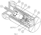
- fig 1 The general layout of a typical electric actuator for sub sea production control is illustrated in fig 1 .
- the combination of a roller screw arrangement 3 and a PM motor drive 2 is considered commonplace and not part of the present invention.
- the bonnet 12 interfaces to a tree or other tubing is a common feature of most such actuators.
- the focal point of the invention is the fail safe mechanism, illustrated as a group 5 of components in fig 1 .
- fig 1 illustrates a complete actuator, all other figures show only the components comprised in the fail safe mechanism.
- the essence of the present invention is the interaction between a return force means, a motor drive train and a trigger mechanism, the intent being to create an actuator of the highest operational reliability, both in terms of the capability to shutdown a production system on command and also to start and maintain the production system operational.
- the basic operating principle is to use the motor 2 and roller screw 3 as a jack to run a stem 4 to operate a gate valve into the production (steady state) condition, apply the failsafe mechanism to hold the stem 4 in this position, wherein forces applied from a return spring 14 (or other equivalent force means) being neutralised by a trigger mechanism, then immediately returning the roller screw assembly to the valve safe position while the valve remains in the production position.
- a return spring 14 or other equivalent force means
- roller screw has free back-drive characteristics, i.e. in the event of an ESD being activated when the roller screw assembly is still in the production position it will not prevent ESD, but the roller screw will be driven, additionally to the motor action, under the action of the return spring to the safe position.
- ESD electrostatic discharge
- SIL is a statistical concept in nature and logarithmic in scale. It is an expression of the statistical probability of success of performing an ESD on command at any time irrespective of operational mode. Thus two redundant schemes, each of high reliability, are bound to have a favourable influence on the SIL rating.
- the move from production position to the safe position falls into two distinct classes:
- ESD 0 and ESD 1 An ESD situation of a more serious class (known in some oil provinces as ESD 0 and ESD 1) may simply cut the power supply, or the power supply may be cut accidentally by the control umbilical being severed by external causes.
- the primary trigger or trigger actuator solenoid 20 or SMA device 30
- the primary trigger or trigger actuator will release an auxiliary trigger spring 21, and latches or latching dogs 25 will go to the de-latch position, thus releasing the return spring 14 and the valve will return to the safe position.
- the roller screw 3 is driven by the motor 2 by means of a VSD unit (not shown) to run the valve stem 4 to the production position.
- a VSD unit (usually an LVDT, not shown) detects that the desired position is achieved
- the solenoid 20 or the SMA element 30 pulls against the auxiliary trigger spring 21 to engage the latching dogs 25 by means of locking pins 29 engaging seats 23 formed in the subject ends of the latch dogs 25.
- the locking pins 29 then prevent the latch dogs from motion as long as the primary trigger/trigger actuator SMA 30 or solenoid 20, connected to and/or acting on a rod-shaped trigger 22, are energised.
- the locking pins 29 are moved out of the blocking position in seats 23, into recesses 24 formed on the trigger rod 22, and the return spring 14 is free to push the stem 4 back to the safer position.
- the latch dogs 25 provide, by virtue of the displaced location of their pivots 26, a leverage mechanism reducing the high contact pressure between the return spring 14 and the latch dogs to a much lower contact pressure between the latch dogs 25 and the locking pins 29.
- the latch dogs 25 and the associated locking pins 29 should preferably be arranged evenly distributed around the center line of the actuator. Preferably three or more latch dogs 25/locking pins 29 should be used.
- the latch dog return springs 27 are provided to return the latches to the engage position awaiting the next push of the jack system.
- the roller screw and motor provide all the energy required to pretension the return spring 14, thus the solenoid 20 or the SMA device 30 is not required to hold the return spring 14 in a compressed state, the trigger actuators 20 and 30 are only required to hold the trigger spring 21 in compression. This reduces the power needed, and thus the electrical power consumption in steady state production mode is correspondingly reduced.
- annular damping cylinder 15 In order to prevent the return-to-safe-position stroke from excessive speeds an annular damping cylinder 15, check valve(s) 16 and flow restrictor(s) 17 as well as seals 19 are provided. Filters 18 may serve to catch particulate contamination in the oil volume and may advantageously be combined with simple check valves (not shown) to make sure the debris is not released from the filters.
- An SMA or a solenoid controlled trigger mechanism both have a characteristic desirable in a sub sea ESD application, i.e. the sluggish response.
- This characteristic which is often a disadvantage in many industrial applications, renders these devices insensitive to glitches in power and communication systems without the benefit of dedicated timers included in the design.
- the delayed action is to the contrary inherent in the operating principle, more so for an SMA device than for a solenoid type device.
- the latter can only be sensibly designed for a delay of around 1 second (order of magnitude) as applied to a sub sea actuator as described in this disclosure. This will for most designs be sufficient.
- a larger delay can be achieved by adding a capacitor across the solenoid winding whenever the natural and inherent delay in a response is considered inadequate.
- the present invention assumes use of a BL DC PM motor of high torque (wide selection available), or other electrical motor, driving a planetary roller screw (typically of such design as is commonly found on the market and in catalogue material) of low pitch to achieve maximum linear force per unit torque offered by the BL DC PM machine.
- a BL DC PM motor of high torque wide selection available
- a planetary roller screw typically of such design as is commonly found on the market and in catalogue material
- Neither of these elements form part of the invention as they appear in a multitude of actuator designs and are thus well established in the public domain.
- Other forms of rotary to linear conversions could also be used. In the following only a roller screw is described, but it should be understood that any rotary to linear conversion unit could be employed.
- roller screw may be designed with a certain pitch to provide free back-drive (the pre-tensioned return spring driving the roller screw into the reverse direction)
- the present invention is based on designing the roller screw for minimum practicable pitch such as to utilize the motor torque to the maximum extent.
- the roller screw will still have free back drive.
- back drive credibility is not a binary issue: The higher the gear ratio of the mechanical drive train, the lower the efficiency of the mechanical train, the higher the exposure to the force of the return spring, the more issues are raised relating to the reliability of the free back drive capability.
- the trigger mechanism comprises an electromagnetic or an SMA part trigger actuator and a leverage mechanism.
- the latter is the same in principle for both embodiments; the trigger actuator representing the difference between the two disclosed embodiments.
- the purpose of the leverage mechanism is to reduce the mechanical force to be handled by the trigger by means of a leverage mechanism, from typically 40 tonnes for a 5 inch actuator to a much smaller value, and also to provide a release mechanism which does not lend itself to galling, i.e. controlled exposure to pressure between two mechanical parts in motion.
- thermo-electrical trigger actuator consists of an SMA based actuation operation. It comprises typically an SMA type wire/rod (typically NiTi alloys) conducting an electrical current in the steady state production mode to retain the wire at a certain temperature higher than the environment (oil). In the ESD mode the power supply is cut off, the SMA wire is cooled down by the ambient oil, the SMA device returns to its alternative shape and the return spring is released to drive the valve to the safe position. On start-up from cold conditions the trigger actuator is set to retain the valve in the less safe position once this position is reached.
- SMA type wire/rod typically NiTi alloys
- SMA materials are in the public domain and known to be elements of actuator design, no attempt to describe their nature is offered as part of this disclosure except to state the purpose of their application, the phase change of such materials as e.g. Ni Ti in response to temperature changes, effectively changing their e-module in a dramatic way, thus facilitating provision of "actuators without moving parts".
- Such actuators may be designed for large forces and typically offer 2-3 per cent elongation for long life times, i.e. a 1 meter rod will extend/contract 3 centimetres in response to a temperature change under suitable operating conditions.
- the basics of SMA designs have been known for more than 20 years and their uses are considered to be in the public domain.
- the primary trigger is a conventional electromechanical solenoid as currently found in a multitude of industrial applications.
- the suggested actuator also facilitates a method of testing ESD functionality without shutting in production. In principle it is desirable that all ESD functionality is tested on a regular basis. It has never been considered prudent, however, to shutdown a high productivity, sub sea production or injection well for the purpose of barrier testing more frequently than once a month.
- the suggested actuator concepts facilitate testing of the ESD capability without sacrifice of production and without significant wear on the equipment.
- the motor and roller screw is used to extend the jack and stem to the open valve position, sufficient to take the loading off the fail safe mechanism.
- the return spring 14 is then allowed to drive the roller screw back a minor distance, corresponding to a minor percentage of the stroke, but sufficient to detect back motion either by means of the LVDT or by measurement of the generator effect in the motor, now running as a synchronous generator.
- full torque is applied on the motor to drive the gate valve back to the ultimate production position.
- the entire motion back and forth may be a small as 1-2 mm and could be covered, if appropriate, by an overlap in the gate valve design, such that the flow cross sectional area is not influenced at all during testing.
Landscapes
- Engineering & Computer Science (AREA)
- General Engineering & Computer Science (AREA)
- Mechanical Engineering (AREA)
- Mechanically-Actuated Valves (AREA)
- Electrically Driven Valve-Operating Means (AREA)
- Preventing Unauthorised Actuation Of Valves (AREA)
Claims (11)
- Absperrschieberstellantrieb mit einer Spindel (4), die in einem mit dem Absperrschieber verbindbaren Stellantriebsgehäuse (10) linear bewegbar ist, wobei die Spindel auf den Absperrschieber wirkt, um den Absperrschieber zwischen offener und geschlossener Stellung zu verschieben, wobei die Spindel (4) durch einen Motor in einer ersten Richtung in eine stationäre Betriebsposition gefahren wird, und in dieser Stellung die Spindel durch ein auf die Spindel (4) wirkendes Federelement (14) in eine zweite entgegengesetzte Richtung zu einer Abschaltposition vorgespannt ist, und einem Auslösemechanismus (22; 25; 29), der angeordnet ist, um das Federelement (14) in einem komprimierten Zustand in einer Halteposition zu halten, wobei der Auslösemechanismus einen elektrisch steuerbaren Auslöser (22; 29) umfasst, der angeordnet ist, um das Federelement (14) infolge der Abschaltung des elektrisch gesteuerten Auslösers (22) freizugeben;
wobei der Auslösemechanismus mindestens eine Verriegelung (25) aufweist, die um einen Drehpunkt (26) schwenkbar in dem Stellantriebsgehäuse gelagert ist, wobei ein erstes Ende der Verriegelung mit der Spindel (4) in Wirkverbindung steht und ein entgegengesetztes zweites Ende der Verriegelung in Wirkverbindung mit dem Auslöser (22) im komprimierten Zustand des Federelementes (14) steht
wobei der Auslöser eine Stange (22) umfasst, die in dem Stellantriebsgehäuse (10) linear bewegbar ist, ein elektrisch angetriebener Auslöserstellantrieb (20; 30) die Stange (22) in die Halteposition treibt, wobei die Stange in die Verriegelung (25) eingreift, und eine Auslöserfeder (21), durch die die Stange beim Abschalten des Auslöserstellantriebs (20; 30) aus der Halteposition in eine zurückgezogene Position gezogen wird, dadurch gekennzeichnet, dass:
die Verriegelung (25) in die Stange (22) indirekt über einen Arretierstift (29) eingreift, der in der Halteposition von der Stange arretiert wird, um in einen Sitz (23) einzugreifen, der am zweiten Ende der Verriegelung ausgebildet ist, und die beim Herausziehen der Stange durch die Verriegelung aus dem Sitz herausgedrückt wird, wodurch der Verriegelung (25) ermöglicht wird, aus dem Eingriff mit der Spindel (4) heraus zu schwenken. - Stellantrieb nach Anspruch 1, dadurch gekennzeichnet, dass beim Herausziehen der Stange (22) der Arretierstift (29) durch die Verriegelung in eine an der Stange ausgebildete Ausnehmung (24) gedrückt wird.
- Stellantrieb nach Anspruch 1 oder 2, dadurch gekennzeichnet, dass die Verriegelung (25) in der freigegebenen Stellung durch eine Verriegelungsrückstellfeder (27) in Richtung der Halteposition vorgespannt ist.
- Stellantrieb nach einem der vorstehenden Ansprüche, wobei der Auslöser (20) ein Magnet ist.
- Stellantrieb nach einem der Ansprüche 1 bis 3, wobei der Auslöser ein Formgedächtnislegierungselement (30) ist.
- Stellantrieb nach einem der vorstehenden Ansprüche, wobei der Auslösemechanismus (22; 25; 29) einen als Hebel ausgebildete Verriegelung (25) umfasst, die aufgrund der Lage des Drehpunkts (26) dazu eingerichtet ist, die vom Federelement (14) auf den Auslösemechanismus übertragene Kraft wesentlich zu reduzieren.
- Stellantrieb nach einem der vorstehenden Ansprüche, dadurch gekennzeichnet, dass die Spindel (4) einen Ringkolben umfasst oder mit einem Ringkolben verbunden ist, der in einem in dem Stellantriebsgehäuse (10) enthaltenen Ringzylinder (15) aufgenommen ist, wobei der Ringzylinder ein Hydraulikmedium zum Dämpfen der Bewegung der Spindel (4) beim Lösen des Federelementes (14) enthält.
- Stellantrieb nach Anspruch 7, wobei das Hydraulikmedium im Ringzylinder (15) über mindestens eine Drosselöffnung (17) mit dem Stellantriebsgehäuse in Strömungsverbindung steht.
- Verfahren zum Verschieben eines Absperrschiebers zwischen einem stationären Betriebsmodus und einem Abschaltbetriebsmodus mittels eines Absperrschieberstellantriebs nach einem der Ansprüche 1 bis 8,
wobei der Stellantrieb von einem Motor in einer ersten Richtung angetrieben wird, um den Absperrschieber in den stationären Betriebsmodus zu versetzen,
gekennzeichnet durch die Schritte:Anordnen einer Kompressionskraft-Einrichtung, um im stationären Betriebsmodus eine Vorspannung auf den Antrieb in einer zweiten Richtung entgegen der ersten Richtung auszuüben, undAntreiben des Stellantriebes in die zweite Richtung durch Freigeben der Kompressionskraft im Abschaltmodus;weiter umfassend: den Schritt des Anordnens eines elektrisch gesteuerten Auslösemechanismus in dem Absperrschieberstellantrieb und des Einschaltens des Auslösemechanismus zum Halten der Kompressionskraft-Einrichtung in dem komprimierten Zustand. - Verfahren nach Anspruch 9, umfassend den Schritt des Einschaltens des Auslösemechanismus durch ein Magnetventil oder durch ein Formgedächtnislegierungs(SMA)-Element.
- Verfahren nach Anspruch 9 oder 10, umfassend den Schritt des Testens der Not-Aus-Funktionalität (ESD) durch:Antreiben des Absperrschieberstellantriebs im stationären Betriebsmodus durch Betätigung des Motors gegen die Kraft der Kompressionskraft-Einrichtung weiter in die erste Richtung; undRückführen des Stellantriebes in den stationären Betriebsmodus durch die Kraft der Kompressionskraft-Einrichtung.
Applications Claiming Priority (2)
| Application Number | Priority Date | Filing Date | Title |
|---|---|---|---|
| NO20080909A NO329102B1 (no) | 2008-02-21 | 2008-02-21 | Sluseventilaktuator og fremgangsmate for a veksle en sluseventil |
| PCT/IB2009/000285 WO2009104072A1 (en) | 2008-02-21 | 2009-02-18 | Gate valve actuator and method |
Publications (3)
| Publication Number | Publication Date |
|---|---|
| EP2255115A1 EP2255115A1 (de) | 2010-12-01 |
| EP2255115A4 EP2255115A4 (de) | 2017-08-02 |
| EP2255115B1 true EP2255115B1 (de) | 2018-10-03 |
Family
ID=40985107
Family Applications (1)
| Application Number | Title | Priority Date | Filing Date |
|---|---|---|---|
| EP09713625.3A Not-in-force EP2255115B1 (de) | 2008-02-21 | 2009-02-18 | Aktor für absperrschieber und verfahren |
Country Status (8)
| Country | Link |
|---|---|
| US (1) | US8398051B2 (de) |
| EP (1) | EP2255115B1 (de) |
| CN (1) | CN102016373B (de) |
| AU (1) | AU2009215339B2 (de) |
| BR (1) | BRPI0907947B1 (de) |
| MY (1) | MY159322A (de) |
| NO (1) | NO329102B1 (de) |
| WO (1) | WO2009104072A1 (de) |
Families Citing this family (15)
| Publication number | Priority date | Publication date | Assignee | Title |
|---|---|---|---|---|
| US8690124B2 (en) * | 2009-12-11 | 2014-04-08 | Ge Oil & Gas Pressure Control Lp | Gate valve |
| US9416606B2 (en) * | 2012-11-14 | 2016-08-16 | Schlumberger Technology Corporation | While drilling valve system |
| US9273597B2 (en) * | 2013-05-16 | 2016-03-01 | Ford Global Technologies, Llc | Method and system for operating an engine turbocharger waste gate |
| US9797490B2 (en) * | 2014-03-27 | 2017-10-24 | Lcdrives Corp. | High reliability actuator |
| US9970564B2 (en) * | 2014-06-04 | 2018-05-15 | Kongsberg Automotive Ab | SMA valve for controlling pressurized air supply to an air cell in a vehicle seat |
| CN105422045B (zh) * | 2016-01-21 | 2017-04-05 | 中国石油大学(华东) | 水下全电采油树系统一体式电动执行器 |
| GB201615080D0 (en) * | 2016-09-06 | 2016-10-19 | Camcon Auto Ltd | Electromagnetic actuator |
| DE102017116108A1 (de) * | 2017-07-18 | 2019-01-24 | Samson Aktiengesellschaft | Stellgerät mit Sicherheitsstellfunktion |
| DE102018100519A1 (de) * | 2018-01-11 | 2019-07-11 | Voith Patent Gmbh | Ventilantrieb mit Schnellfahrfunktion |
| CN109140026B (zh) * | 2018-10-23 | 2019-11-01 | 哈尔滨工程大学 | 一种全电式水下闸阀执行器 |
| DE102020112548A1 (de) | 2020-05-08 | 2021-11-11 | Auma Riester Gmbh & Co. Kg | Fail-Safe-Antrieb und Stellantrieb mit einem Fail-Safe-Antrieb |
| CN112590044A (zh) * | 2020-12-07 | 2021-04-02 | 高宾 | 一种防止胶体凝固的纽扣塑形机 |
| US11953117B2 (en) | 2021-01-20 | 2024-04-09 | Saudi Arabian Oil Company | Gate valve indicator devices for oil and gas applications |
| DE102021206036A1 (de) * | 2021-06-14 | 2022-12-15 | MAGENTA GmbH Mechatronische und Kinematische Systeme | Auslöseeinrichtung und Anordnung mit einer Auslöseeinrichtung |
| US12571475B2 (en) * | 2024-02-09 | 2026-03-10 | Fmc Technologies, Inc. | Gate valve with positive gate stop |
Family Cites Families (14)
| Publication number | Priority date | Publication date | Assignee | Title |
|---|---|---|---|---|
| US2962036A (en) * | 1957-02-13 | 1960-11-29 | Baso Inc | Control device |
| US3324741A (en) * | 1965-06-15 | 1967-06-13 | Acf Ind Inc | Valve operator |
| US3512421A (en) * | 1966-09-02 | 1970-05-19 | Acf Ind Inc | Fail-safe valve operator |
| US4619320A (en) * | 1984-03-02 | 1986-10-28 | Memory Metals, Inc. | Subsurface well safety valve and control system |
| US4872638A (en) * | 1988-01-29 | 1989-10-10 | Semitool, Inc. | Slow acting fluid valve |
| FR2773865B1 (fr) * | 1998-01-21 | 2000-03-24 | Theobald A | Vanne de reglage de debit |
| US6129366A (en) * | 1998-07-10 | 2000-10-10 | Wenger Corporation | Mobile teaching station |
| US6129333A (en) * | 1998-08-14 | 2000-10-10 | Young & Franklin | Spring locking mechanism |
| GB9920166D0 (en) | 1999-08-25 | 1999-10-27 | Alpha Thames Limited | Valve actuator |
| DE20018564U1 (de) * | 2000-10-30 | 2002-03-21 | CAMERON GmbH, 29227 Celle | Betätigungsvorrichtung |
| US6619388B2 (en) * | 2001-02-15 | 2003-09-16 | Halliburton Energy Services, Inc. | Fail safe surface controlled subsurface safety valve for use in a well |
| US6676105B2 (en) * | 2001-12-20 | 2004-01-13 | Eaton Corporation | Self-contained hydraulic dampening for a solenoid operated spool valve |
| GB2383627A (en) | 2001-12-31 | 2003-07-02 | Abb Offshore Systems Ltd | Fail safe valve actuator |
| US7143993B2 (en) * | 2003-01-17 | 2006-12-05 | Siemens Vdo Automotive, Inc. | Exhaust gas recirculation valve having a rotary motor |
-
2008
- 2008-02-21 NO NO20080909A patent/NO329102B1/no unknown
-
2009
- 2009-02-18 WO PCT/IB2009/000285 patent/WO2009104072A1/en not_active Ceased
- 2009-02-18 BR BRPI0907947-5A patent/BRPI0907947B1/pt not_active IP Right Cessation
- 2009-02-18 AU AU2009215339A patent/AU2009215339B2/en not_active Ceased
- 2009-02-18 MY MYPI2010003707A patent/MY159322A/en unknown
- 2009-02-18 US US12/918,933 patent/US8398051B2/en not_active Expired - Fee Related
- 2009-02-18 CN CN2009801066126A patent/CN102016373B/zh not_active Expired - Fee Related
- 2009-02-18 EP EP09713625.3A patent/EP2255115B1/de not_active Not-in-force
Non-Patent Citations (1)
| Title |
|---|
| None * |
Also Published As
| Publication number | Publication date |
|---|---|
| CN102016373A (zh) | 2011-04-13 |
| NO20080909L (no) | 2009-08-24 |
| BRPI0907947A2 (pt) | 2015-08-04 |
| NO329102B1 (no) | 2010-08-23 |
| EP2255115A1 (de) | 2010-12-01 |
| CN102016373B (zh) | 2013-06-12 |
| EP2255115A4 (de) | 2017-08-02 |
| US8398051B2 (en) | 2013-03-19 |
| AU2009215339B2 (en) | 2014-06-19 |
| AU2009215339A1 (en) | 2009-08-27 |
| WO2009104072A1 (en) | 2009-08-27 |
| MY159322A (en) | 2016-12-30 |
| BRPI0907947B1 (pt) | 2020-10-20 |
| US20110068287A1 (en) | 2011-03-24 |
Similar Documents
| Publication | Publication Date | Title |
|---|---|---|
| EP2255115B1 (de) | Aktor für absperrschieber und verfahren | |
| EP4028635B1 (de) | Untergrundsicherheitsventil und verfahren zum betrieb eines untergrundsicherheitsventils | |
| US5984260A (en) | Electrically driven actuator with failsafe feature | |
| US6619388B2 (en) | Fail safe surface controlled subsurface safety valve for use in a well | |
| US9470330B2 (en) | Actuating device and method for displacing the actuating device | |
| FR2577647A1 (fr) | Vanne de surete pour puits actionnee par solenoide | |
| WO2008125136A1 (en) | Actuating device and method of operating an actuating device | |
| US6585228B1 (en) | Electric valve actuator with eddy current clutch | |
| JP5048671B2 (ja) | 緊急分離システム | |
| EP3645829B1 (de) | Ausfallsicherer elektroventilbetätiger | |
| US6152167A (en) | Valve actuator with emergency shutdown feature | |
| EP2545247B1 (de) | Bohrlochbarriere | |
| RU2402712C2 (ru) | Привод клапана и клапанное устройство | |
| WO2019002906A1 (en) | ELECTRICAL VALVE ACTUATOR WITH INTEGRATED SAFETY | |
| CA2852252C (en) | Downhole tool actuator | |
| KR101422222B1 (ko) | 패시브 블로아웃 방지장치 | |
| Ahmadli et al. | Analysis of all-electric subsea gate valve designs and system overview | |
| CN106151666B (zh) | 一种水下闸阀执行器的低功耗保持及失效安全关断机构 | |
| GB2378744A (en) | Control valves |
Legal Events
| Date | Code | Title | Description |
|---|---|---|---|
| PUAI | Public reference made under article 153(3) epc to a published international application that has entered the european phase |
Free format text: ORIGINAL CODE: 0009012 |
|
| 17P | Request for examination filed |
Effective date: 20100914 |
|
| AK | Designated contracting states |
Kind code of ref document: A1 Designated state(s): AT BE BG CH CY CZ DE DK EE ES FI FR GB GR HR HU IE IS IT LI LT LU LV MC MK MT NL NO PL PT RO SE SI SK TR |
|
| AX | Request for extension of the european patent |
Extension state: AL BA RS |
|
| DAX | Request for extension of the european patent (deleted) | ||
| RA4 | Supplementary search report drawn up and despatched (corrected) |
Effective date: 20170630 |
|
| RIC1 | Information provided on ipc code assigned before grant |
Ipc: F16K 31/56 20060101ALI20170626BHEP Ipc: F16K 3/02 20060101ALI20170626BHEP Ipc: F16K 31/04 20060101AFI20170626BHEP Ipc: E21B 34/06 20060101ALI20170626BHEP Ipc: F16K 31/00 20060101ALI20170626BHEP |
|
| GRAP | Despatch of communication of intention to grant a patent |
Free format text: ORIGINAL CODE: EPIDOSNIGR1 |
|
| STAA | Information on the status of an ep patent application or granted ep patent |
Free format text: STATUS: GRANT OF PATENT IS INTENDED |
|
| INTG | Intention to grant announced |
Effective date: 20180514 |
|
| GRAS | Grant fee paid |
Free format text: ORIGINAL CODE: EPIDOSNIGR3 |
|
| GRAA | (expected) grant |
Free format text: ORIGINAL CODE: 0009210 |
|
| STAA | Information on the status of an ep patent application or granted ep patent |
Free format text: STATUS: THE PATENT HAS BEEN GRANTED |
|
| AK | Designated contracting states |
Kind code of ref document: B1 Designated state(s): AT BE BG CH CY CZ DE DK EE ES FI FR GB GR HR HU IE IS IT LI LT LU LV MC MK MT NL NO PL PT RO SE SI SK TR |
|
| REG | Reference to a national code |
Ref country code: GB Ref legal event code: FG4D |
|
| REG | Reference to a national code |
Ref country code: CH Ref legal event code: EP Ref country code: AT Ref legal event code: REF Ref document number: 1048974 Country of ref document: AT Kind code of ref document: T Effective date: 20181015 |
|
| REG | Reference to a national code |
Ref country code: IE Ref legal event code: FG4D Ref country code: DE Ref legal event code: R096 Ref document number: 602009054851 Country of ref document: DE |
|
| REG | Reference to a national code |
Ref country code: NL Ref legal event code: FP |
|
| REG | Reference to a national code |
Ref country code: LT Ref legal event code: MG4D |
|
| REG | Reference to a national code |
Ref country code: AT Ref legal event code: MK05 Ref document number: 1048974 Country of ref document: AT Kind code of ref document: T Effective date: 20181003 |
|
| PG25 | Lapsed in a contracting state [announced via postgrant information from national office to epo] |
Ref country code: ES Free format text: LAPSE BECAUSE OF FAILURE TO SUBMIT A TRANSLATION OF THE DESCRIPTION OR TO PAY THE FEE WITHIN THE PRESCRIBED TIME-LIMIT Effective date: 20181003 Ref country code: LV Free format text: LAPSE BECAUSE OF FAILURE TO SUBMIT A TRANSLATION OF THE DESCRIPTION OR TO PAY THE FEE WITHIN THE PRESCRIBED TIME-LIMIT Effective date: 20181003 Ref country code: PL Free format text: LAPSE BECAUSE OF FAILURE TO SUBMIT A TRANSLATION OF THE DESCRIPTION OR TO PAY THE FEE WITHIN THE PRESCRIBED TIME-LIMIT Effective date: 20181003 Ref country code: CZ Free format text: LAPSE BECAUSE OF FAILURE TO SUBMIT A TRANSLATION OF THE DESCRIPTION OR TO PAY THE FEE WITHIN THE PRESCRIBED TIME-LIMIT Effective date: 20181003 Ref country code: HR Free format text: LAPSE BECAUSE OF FAILURE TO SUBMIT A TRANSLATION OF THE DESCRIPTION OR TO PAY THE FEE WITHIN THE PRESCRIBED TIME-LIMIT Effective date: 20181003 Ref country code: BG Free format text: LAPSE BECAUSE OF FAILURE TO SUBMIT A TRANSLATION OF THE DESCRIPTION OR TO PAY THE FEE WITHIN THE PRESCRIBED TIME-LIMIT Effective date: 20190103 Ref country code: LT Free format text: LAPSE BECAUSE OF FAILURE TO SUBMIT A TRANSLATION OF THE DESCRIPTION OR TO PAY THE FEE WITHIN THE PRESCRIBED TIME-LIMIT Effective date: 20181003 Ref country code: FI Free format text: LAPSE BECAUSE OF FAILURE TO SUBMIT A TRANSLATION OF THE DESCRIPTION OR TO PAY THE FEE WITHIN THE PRESCRIBED TIME-LIMIT Effective date: 20181003 Ref country code: IS Free format text: LAPSE BECAUSE OF FAILURE TO SUBMIT A TRANSLATION OF THE DESCRIPTION OR TO PAY THE FEE WITHIN THE PRESCRIBED TIME-LIMIT Effective date: 20190203 Ref country code: NO Free format text: LAPSE BECAUSE OF FAILURE TO SUBMIT A TRANSLATION OF THE DESCRIPTION OR TO PAY THE FEE WITHIN THE PRESCRIBED TIME-LIMIT Effective date: 20190103 Ref country code: AT Free format text: LAPSE BECAUSE OF FAILURE TO SUBMIT A TRANSLATION OF THE DESCRIPTION OR TO PAY THE FEE WITHIN THE PRESCRIBED TIME-LIMIT Effective date: 20181003 |
|
| PG25 | Lapsed in a contracting state [announced via postgrant information from national office to epo] |
Ref country code: GR Free format text: LAPSE BECAUSE OF FAILURE TO SUBMIT A TRANSLATION OF THE DESCRIPTION OR TO PAY THE FEE WITHIN THE PRESCRIBED TIME-LIMIT Effective date: 20190104 Ref country code: SE Free format text: LAPSE BECAUSE OF FAILURE TO SUBMIT A TRANSLATION OF THE DESCRIPTION OR TO PAY THE FEE WITHIN THE PRESCRIBED TIME-LIMIT Effective date: 20181003 Ref country code: PT Free format text: LAPSE BECAUSE OF FAILURE TO SUBMIT A TRANSLATION OF THE DESCRIPTION OR TO PAY THE FEE WITHIN THE PRESCRIBED TIME-LIMIT Effective date: 20190203 |
|
| REG | Reference to a national code |
Ref country code: DE Ref legal event code: R097 Ref document number: 602009054851 Country of ref document: DE |
|
| PG25 | Lapsed in a contracting state [announced via postgrant information from national office to epo] |
Ref country code: DK Free format text: LAPSE BECAUSE OF FAILURE TO SUBMIT A TRANSLATION OF THE DESCRIPTION OR TO PAY THE FEE WITHIN THE PRESCRIBED TIME-LIMIT Effective date: 20181003 |
|
| PLBE | No opposition filed within time limit |
Free format text: ORIGINAL CODE: 0009261 |
|
| STAA | Information on the status of an ep patent application or granted ep patent |
Free format text: STATUS: NO OPPOSITION FILED WITHIN TIME LIMIT |
|
| PG25 | Lapsed in a contracting state [announced via postgrant information from national office to epo] |
Ref country code: RO Free format text: LAPSE BECAUSE OF FAILURE TO SUBMIT A TRANSLATION OF THE DESCRIPTION OR TO PAY THE FEE WITHIN THE PRESCRIBED TIME-LIMIT Effective date: 20181003 Ref country code: SK Free format text: LAPSE BECAUSE OF FAILURE TO SUBMIT A TRANSLATION OF THE DESCRIPTION OR TO PAY THE FEE WITHIN THE PRESCRIBED TIME-LIMIT Effective date: 20181003 Ref country code: EE Free format text: LAPSE BECAUSE OF FAILURE TO SUBMIT A TRANSLATION OF THE DESCRIPTION OR TO PAY THE FEE WITHIN THE PRESCRIBED TIME-LIMIT Effective date: 20181003 |
|
| REG | Reference to a national code |
Ref country code: DE Ref legal event code: R119 Ref document number: 602009054851 Country of ref document: DE |
|
| 26N | No opposition filed |
Effective date: 20190704 |
|
| REG | Reference to a national code |
Ref country code: CH Ref legal event code: PL |
|
| PG25 | Lapsed in a contracting state [announced via postgrant information from national office to epo] |
Ref country code: SI Free format text: LAPSE BECAUSE OF FAILURE TO SUBMIT A TRANSLATION OF THE DESCRIPTION OR TO PAY THE FEE WITHIN THE PRESCRIBED TIME-LIMIT Effective date: 20181003 Ref country code: LU Free format text: LAPSE BECAUSE OF NON-PAYMENT OF DUE FEES Effective date: 20190218 Ref country code: MC Free format text: LAPSE BECAUSE OF FAILURE TO SUBMIT A TRANSLATION OF THE DESCRIPTION OR TO PAY THE FEE WITHIN THE PRESCRIBED TIME-LIMIT Effective date: 20181003 |
|
| REG | Reference to a national code |
Ref country code: BE Ref legal event code: MM Effective date: 20190228 |
|
| REG | Reference to a national code |
Ref country code: IE Ref legal event code: MM4A |
|
| PG25 | Lapsed in a contracting state [announced via postgrant information from national office to epo] |
Ref country code: LI Free format text: LAPSE BECAUSE OF NON-PAYMENT OF DUE FEES Effective date: 20190228 Ref country code: CH Free format text: LAPSE BECAUSE OF NON-PAYMENT OF DUE FEES Effective date: 20190228 |
|
| PG25 | Lapsed in a contracting state [announced via postgrant information from national office to epo] |
Ref country code: DE Free format text: LAPSE BECAUSE OF NON-PAYMENT OF DUE FEES Effective date: 20190903 Ref country code: IE Free format text: LAPSE BECAUSE OF NON-PAYMENT OF DUE FEES Effective date: 20190218 |
|
| PG25 | Lapsed in a contracting state [announced via postgrant information from national office to epo] |
Ref country code: BE Free format text: LAPSE BECAUSE OF NON-PAYMENT OF DUE FEES Effective date: 20190228 |
|
| PG25 | Lapsed in a contracting state [announced via postgrant information from national office to epo] |
Ref country code: TR Free format text: LAPSE BECAUSE OF FAILURE TO SUBMIT A TRANSLATION OF THE DESCRIPTION OR TO PAY THE FEE WITHIN THE PRESCRIBED TIME-LIMIT Effective date: 20181003 |
|
| PG25 | Lapsed in a contracting state [announced via postgrant information from national office to epo] |
Ref country code: MT Free format text: LAPSE BECAUSE OF NON-PAYMENT OF DUE FEES Effective date: 20190218 |
|
| PG25 | Lapsed in a contracting state [announced via postgrant information from national office to epo] |
Ref country code: CY Free format text: LAPSE BECAUSE OF FAILURE TO SUBMIT A TRANSLATION OF THE DESCRIPTION OR TO PAY THE FEE WITHIN THE PRESCRIBED TIME-LIMIT Effective date: 20181003 |
|
| PG25 | Lapsed in a contracting state [announced via postgrant information from national office to epo] |
Ref country code: HU Free format text: LAPSE BECAUSE OF FAILURE TO SUBMIT A TRANSLATION OF THE DESCRIPTION OR TO PAY THE FEE WITHIN THE PRESCRIBED TIME-LIMIT; INVALID AB INITIO Effective date: 20090218 |
|
| PG25 | Lapsed in a contracting state [announced via postgrant information from national office to epo] |
Ref country code: MK Free format text: LAPSE BECAUSE OF FAILURE TO SUBMIT A TRANSLATION OF THE DESCRIPTION OR TO PAY THE FEE WITHIN THE PRESCRIBED TIME-LIMIT Effective date: 20181003 |
|
| PGFP | Annual fee paid to national office [announced via postgrant information from national office to epo] |
Ref country code: FR Payment date: 20230119 Year of fee payment: 15 |
|
| PGFP | Annual fee paid to national office [announced via postgrant information from national office to epo] |
Ref country code: IT Payment date: 20230120 Year of fee payment: 15 Ref country code: GB Payment date: 20230120 Year of fee payment: 15 |
|
| PGFP | Annual fee paid to national office [announced via postgrant information from national office to epo] |
Ref country code: NL Payment date: 20230119 Year of fee payment: 15 |
|
| REG | Reference to a national code |
Ref country code: NL Ref legal event code: MM Effective date: 20240301 |
|
| GBPC | Gb: european patent ceased through non-payment of renewal fee |
Effective date: 20240218 |
|
| PG25 | Lapsed in a contracting state [announced via postgrant information from national office to epo] |
Ref country code: NL Free format text: LAPSE BECAUSE OF NON-PAYMENT OF DUE FEES Effective date: 20240301 |
|
| PG25 | Lapsed in a contracting state [announced via postgrant information from national office to epo] |
Ref country code: NL Free format text: LAPSE BECAUSE OF NON-PAYMENT OF DUE FEES Effective date: 20240301 |
|
| PG25 | Lapsed in a contracting state [announced via postgrant information from national office to epo] |
Ref country code: GB Free format text: LAPSE BECAUSE OF NON-PAYMENT OF DUE FEES Effective date: 20240218 |
|
| PG25 | Lapsed in a contracting state [announced via postgrant information from national office to epo] |
Ref country code: FR Free format text: LAPSE BECAUSE OF NON-PAYMENT OF DUE FEES Effective date: 20240229 |
|
| PG25 | Lapsed in a contracting state [announced via postgrant information from national office to epo] |
Ref country code: GB Free format text: LAPSE BECAUSE OF NON-PAYMENT OF DUE FEES Effective date: 20240218 Ref country code: FR Free format text: LAPSE BECAUSE OF NON-PAYMENT OF DUE FEES Effective date: 20240229 |
|
| PG25 | Lapsed in a contracting state [announced via postgrant information from national office to epo] |
Ref country code: IT Free format text: LAPSE BECAUSE OF NON-PAYMENT OF DUE FEES Effective date: 20240218 |