EP2254211A2 - Telescoping wire cable tray system - Google Patents
Telescoping wire cable tray system Download PDFInfo
- Publication number
- EP2254211A2 EP2254211A2 EP10163342A EP10163342A EP2254211A2 EP 2254211 A2 EP2254211 A2 EP 2254211A2 EP 10163342 A EP10163342 A EP 10163342A EP 10163342 A EP10163342 A EP 10163342A EP 2254211 A2 EP2254211 A2 EP 2254211A2
- Authority
- EP
- European Patent Office
- Prior art keywords
- wire cable
- cable tray
- wire
- tray system
- wires
- Prior art date
- Legal status (The legal status is an assumption and is not a legal conclusion. Google has not performed a legal analysis and makes no representation as to the accuracy of the status listed.)
- Granted
Links
Images


Classifications
-
- H—ELECTRICITY
- H02—GENERATION; CONVERSION OR DISTRIBUTION OF ELECTRIC POWER
- H02G—INSTALLATION OF ELECTRIC CABLES OR LINES, OR OF COMBINED OPTICAL AND ELECTRIC CABLES OR LINES
- H02G3/00—Installations of electric cables or lines or protective tubing therefor in or on buildings, equivalent structures or vehicles
- H02G3/02—Details
- H02G3/04—Protective tubing or conduits, e.g. cable ladders or cable troughs
- H02G3/0437—Channels
- H02G3/0443—Channels formed by wire or analogous netting
-
- H—ELECTRICITY
- H02—GENERATION; CONVERSION OR DISTRIBUTION OF ELECTRIC POWER
- H02G—INSTALLATION OF ELECTRIC CABLES OR LINES, OR OF COMBINED OPTICAL AND ELECTRIC CABLES OR LINES
- H02G3/00—Installations of electric cables or lines or protective tubing therefor in or on buildings, equivalent structures or vehicles
- H02G3/02—Details
- H02G3/06—Joints for connecting lengths of protective tubing or channels, to each other or to casings, e.g. to distribution boxes; Ensuring electrical continuity in the joint
- H02G3/0608—Joints for connecting non cylindrical conduits, e.g. channels
Definitions
- the present invention relates to a wire cable tray system and, in particular, the invention relates to a telescoping wire cable tray system with adjustable length wire cable trays to accommodate various overhead applications.
- Wire cable tray systems are used in data centers and other areas to run cables overhead or below raised floors. Cable tray systems are generally shipped in long sections (e.g., 10 feet) and cut to fit during installation. Cutting and deburring cable trays during installation is very time consuming, and the cut ends can be sharp.
- a wire cable tray system comprised of a plurality of wire cable trays and at least one trapeze support device for supporting the wire cable trays.
- the wire cable trays include a plurality of transverse wires and a plurality of longitudinal wires.
- the trapeze support device includes a trapeze support bar and at least one locking clip.
- the trapeze support bar includes a channel defined by a bottom and side walls extending from the bottom. The side walls include an upper support surface and a lower support surface. The locking clip slides over the channel to secure the trapeze support device to the wire cable trays.
- a wire cable tray system comprising:
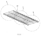
- Figs. 1-4 illustrate the telescoping wire cable tray system 20 of the present invention.
- the telescoping wire cable tray system 20 includes an outer wire cable tray 30 and an inner wire cable tray 50.
- Each wire cable tray includes a plurality of transverse wires 32, 52 and a plurality of longitudinal wires 42, 62.
- the transverse wires 32, 52 form a generally flat top 40 for supporting cables routed in the wire cable tray system 20.
- each transverse wire 32 of the outer wire cable tray 30 includes a top portion 34, side walls portions 36 and bottom portions 38.
- the outer wire cable tray 30 includes longitudinal wires 42 positioned underneath the top portion 34 of the transverse wires 32.
- the three longitudinal wires 42 are parallel and are positioned an equal distance apart, and they provide support to the transverse wires 32.
- a longitudinal wire 42 is also positioned above each bottom portion 38 of the transverse wires 32 at the end of the transverse wires 32 thereby forming a slot or track 44 between the side walls 36 of the transverse wires 32 and the longitudinal wire 42.
- the transverse wires 52 of the inner wire cable tray 50 include a top portion 54 and side walls 56.
- the inner wire cable tray 50 includes three parallel longitudinal wires 62 positioned above the transverse wires 52 and a longitudinal wire 62 positioned at the end of each side wall 56 of the transverse wires 52.
- the longitudinal wires 62 of the inner wire cable tray 50 and the longitudinal wires 42 of the outer wire cable tray 30 are positioned adjacent to each other allowing the wire cable trays to slide or telescope with respect to each other to adjust the length of the wire cable tray system.
- the longitudinal wires 62 at the end of the transverse wires 52 of the inner wire cable tray 50 are positioned in the slot or track 44 formed by the longitudinal wires 42 and the side walls 36 of the transverse wires 32 thereby restricting the relative lateral movement of the wire cable trays as the wire cable trays telescope with respect to each other.
- the outer and inner wire cable trays are designed with a 100mm x 9.5 in. grid spacing to enable the wire cable tray openings to align with cabinet top openings in a line of standard cabinets of various standard widths. Typically, there are three standard widths of data center cabinets. Each of these standard widths is a multiple of the distance between transverse wires of the wire cable tray. For example, the wire cable tray system openings approximately align with Panduit's NET-ACCESSTM cabinet top openings illustrated and described in U.S. Patent No. 7,498,512 .
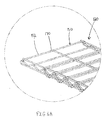
- Figs. 5-12 illustrate the components and assembly of an alternative embodiment of the telescoping wire cable tray system 20, referred to as wire cable tray system 120.
- the wire cable tray system 120 includes truss style side walls to strengthen the structure of the wire cable trays.
- Figs. 7-8 illustrate the truss style side walls 132 of the outer wire cable tray 130 formed by the transverse wires 134.
- the transverse wires 134 include a top portion 136, a downwardly extending diagonal wall 138 which loops to form a flat bottom portion 140 and an upwardly extending diagonal wall 142 that ends with a transverse stub 144.
- Each transverse stub 144 is positioned adjacent to the top portion 136 of an adjacent transverse wire 134.
- the longitudinal wires 146 of the outer wire cable tray 130 are positioned underneath the top portion 136 of the transverse wires 134.
- a longitudinal wire 146 is also positioned at each end of the bottom portions 140 to form a slot or track 148 (see Fig. 12 ) between the side walls 132 of the transverse wires 134 and the longitudinal wire 146.
- Figs. 9 and 10 illustrate the truss style side walls 151 of the inner wire cable tray 150 formed by the transverse wires 152 and a longitudinal side wire 162.
- the transverse wires 152 include a top portion 154, a downwardly extending wall 156 and an upwardly extending wall 158 ending in a stub 160.
- Each stub 160 is positioned adjacent to the top portion 154 of an adjacent transverse wire 152.
- the longitudinal side wire 162 is positioned adjacent to the intersection of the downwardly extending wall 156 and the upwardly extending wall 158.
- the longitudinal side wire 162 includes a bottom portion 164, a curved portion 166 and a top portion 168.
- the bottom portion 164 of the longitudinal side wire 162 generally extends the length of the inner wire cable tray 150.
- the longitudinal side wire 162 is designed to slide in the slot or track 148 to provide a smooth telescoping action over the outer wire cable tray 130.
- the inner wire cable tray 150 also includes longitudinal wires 170 that are positioned above the top portion 154 of the transverse wires 152.
- Fig. 13 illustrates a prior art bend radius downspout fitting 200 including a top portion 202 with a bend radius portion 204 extending from one end.
- the bend radius fitting 200 includes snaps 206, and the bend radius fitting 200 snaps onto adjacent longitudinal wires to cover the area between adjacent transverse wires.
- the bend radius portion 204 extends downward into an open area 208 between the transverse wires. As a result, the bend radius portion 204 reduces the available open area 208 for cables to exit the wire cable tray system.
- Figs. 14-16 illustrate a bend radius fitting 220 for the wire cable tray system.
- the bend radius fitting 220 includes a bend radius portion 222, two side flanges 224 and two snap features 226 positioned along the bottom of the bend radius fitting 220.
- the bend radius fitting 220 is snapped onto adjacent transverse wires. As best seen in Fig. 15 , the bend radius fitting 220 does not extend into the open area 228, thus the entire open area 228 is available for cables exiting the wire cable tray system.
- Fig. 16 illustrates cables routed from opposite directions and descending through a common open area 228 in the wire cable tray system.
- the bend radius fitting 220 provides maximum space to route cables and cable connectors through an open area in the wire cable tray while minimizing the spacing between transverse wires in the wire cable tray, which minimizes the sag between the transverse wires of cables supported by the wire cable tray.
- the bend radius fitting 220 also increases the number of options for longitudinal locations of downspouts in the wire cable tray system.
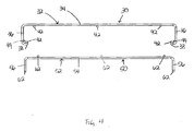
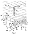
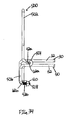
- Figs. 17-19 illustrate a trapeze support bar 300 and a hanger bar 340 that support the telescoping wire cable tray system 20 suspended from ceiling member 370.
- Figs. 17-19 illustrate the overlapping wire cable trays of Fig. 1B attached to the trapeze support bar 300, the trapeze support bar 300 and the hanger bar 340 may also support the inner wire cable tray 50 of Fig. 1A and the outer wire cable tray 30 of Fig. 1C .
- the trapeze support bar 300 includes a channel 302 defined by a bottom 303 having a hole 304 and side walls 305.
- the channel 302 also includes a lower support surface 310, support arms 309 and an upper support surface 306 that extend from the side walls 305.
- the upper support surface 306 includes outwardly extending flanges 308 that support the upper longitudinal wires 42a, 62a of the overlapping outer and inner wire cable trays 30, 50, respectively.
- the lower support surface 310 includes inwardly extending flanges 312 that support the lower longitudinal wires 42b, 62b of the overlapping outer and inner wire cable trays, 30, 50, respectively.
- a locking clip 320 secures the wire cable trays to the trapeze support bar 300.
- the locking clip 320 includes a bottom member 322 with side walls 324 extending therefrom. Each side wall 324 includes a hook 326 for engaging the lower longitudinal wires 42b, 62b of the outer and inner wire cable trays 30, 50.
- the locking clip 320 slides over the trapeze support bar 300 until the hooks 326 engage the lower longitudinal wires 42b, 62b.
- a screw 328, or other fastener secures the locking clip 320 to the trapeze support bar 300 and the outer and inner wire cable trays 30, 50.
- the hanger bar 340 includes an upper hanger bar 342 and a lower hanger bar 352.
- the upper hanger bar 342 and the lower hanger bar 352 each include a plurality of holes 344, 354, respectively.
- a first end 356 of the lower hanger bar 352 is secured to the trapeze support bar 300 by a nut and a bolt.
- a second end 358 of the lower hanger bar 352 mates with a first end 346 of the upper hanger bar 342 so that the lower hanger bar 352 slides inside the upper hanger bar 342.
- the holes 344 in the upper hanger bar 342 and the holes 354 in lower hanger bar 352 align to receive a bolt to lock the upper hanger bar 342 and lower hanger bar 352 at a designated height position.
- a second end 348 of the upper hanger bar 342 is fastened to the ceiling member 370 to suspend the wire cable trays.
- Fig. 20 illustrates the telescoping wire cable trays of the present invention installed on the trapeze support bar 300 and connected to a ceiling member by a threaded rod 380.
- the threaded rod 380 may be used as an alternative to the upper and lower hanger bars 342, 352 illustrated in Figs. 17-19 to secure the telescoping wire cable trays to the ceiling member 370.
- a first end 382 of the threaded rod 380 is secured to the trapeze support bar 300 and a second end 384 of the threaded rod 380 is secured to a ceiling member.
- Figs. 21-26 illustrate a clamp 400 that is used to lock the overlapping outer wire cable tray 30 and the inner wire cable tray 50 of the telescoping wire cable tray system 20.
- Figs. 21-23 illustrate the clamp 400 being installed on the outer cable wire tray 30 and the inner cable wire tray 50.
- the clamp 400 is formed in an open position to facilitate installing the clamp 400 over the lower longitudinal wires 42b, 62b of the outer wire cable tray 30 and the inner wire cable tray 50.
- the clamp 400 includes a top member 402, a bottom member 404 and a hook 406.
- the bottom member 404 of the clamp 400 includes a slot 408 for receiving a screw 418, or other fastener, and a retaining clip 410 for holding the screw 418 in place as the clamp 400 is installed on the lower longitudinal wires 42b, 62b of the overlapping wire cable trays.
- the bottom member 404 also includes paint piercing edges 412 that extend inward toward the top member 402 of the clamp 400.
- the top member 402 includes a fastener 414 for receiving the screw 418 and paint piercing edges 416 that extend inward toward the bottom member 404 of the clamp 400.
- the screw 418 is threaded into the fastener 414.
- the screw 418 is then tightened until the clamp 400 is closed.
- the paint piercing edges 412, 416 are driven into the lower longitudinal wires 42b, 62b of the overlapping outer and inner wire cable trays 30, 50 (see Figs. 24-26 ). Once the screw 418 has been fully tightened, the outer and inner wire cable trays 30, 50 are locked together.
- the paint piercing edges 412, 416 formed in the clamp 400 allow the clamp 400 to create an electrical and mechanical bond with the wire cable trays.
- the hook 406 of the clamp 400 is wrapped around the side wall 36 of the transverse wire 32 of the outer cable tray 30 and the side wall 56 of the transverse wire 52 of the inner wire cable tray 50 to align the transverse wires 32, 52 of the wire cable trays.
- Figs. 21-26 illustrate the clamp 400 attached to the overlapping wire cable trays of Fig. 1B
- the clamp 400 may also be attached to the inner wire cable tray 50 of Fig. 1A and the outer wire cable tray 30 of Fig. 1C .
- Fig. 27 illustrates an alternative clamp 420 having a double hook 422.
- the double hook 422 allows the clamp 420 to be installed on either side of the side walls 36, 56 of the outer and inner wire cable trays 30, 50.
- Figs. 28-35 illustrate a wire form side wall 500 designed to be used on the telescoping wire cable tray system 20.
- the wire form side wall 500 creates a vertical wall along the sides of the wire cable trays for supporting cable routed on the wire cable trays.
- the wire form side wall 500 has an open frame design so that it can be deployed anywhere along the wire cable trays.
- the wire form side wall 500 may be mounted on the inner wire cable tray 50 of Fig. 1A (see Figs. 28 and 29 ), the outer wire cable tray 30 of Fig. 1C (see Figs. 30 and 31 ) and the overlapping wire cable trays of Fig. 1B (see Figs. 32-34 ).
- the wire form side wall 500 is installed on the inner wire cable tray 50 of Fig. 1A .
- the wire form side wall 500 includes an upper portion 502 that extends above the wire cable tray 50, a loop portion 504 and a lower portion 506 with two ends 508.
- the loop portion 504 loops around the upper longitudinal wires 62a of the inner wire cable tray 50 connecting the upper portion 502 and the lower portion 506 of the wire form side wall 500.
- the two ends 508 of the lower portion 506 are threaded.
- a hex nut 510 or a push nut is installed on each threaded end.
- a push nut with a cap to cover the ends of the threads may also be installed.
- the nut 510 is tightened up to the lower longitudinal wire 62b of the inner wire cable tray 50 (see Fig. 29 ).
- Figs. 30 and 31 illustrate the wire form side wall 500 installed on the outer wire cable tray 30 of Fig. 1C .
- the wire form side wall 500 includes an upper portion 502, a loop portion 504 and a lower portion 506 with threaded ends 508.
- the upper portion 502 extends above the outer wire cable tray 30 and the loop portion 506 loops around the upper longitudinal wires 42a connecting the upper portion 502 to the lower portion 506.
- the upper longitudinal wire 42a is positioned at the opening 505 of the loop portion 504.
- a nut 510 is installed on each threaded end 508 and is tightened up to the lower longitudinal wire 42b of the outer wire cable tray 30.
- Figs. 32-34 illustrate the wire form side wall 500 installed on the overlapping wire cable trays 30, 50 of Fig. 1B .
- Fig. 33 illustrates a typical installation process of the wire form side wall 500.
- the nuts 510 are preinstalled on the ends 508 of the wire form side wall 500.
- the wire form side wall 500 is positioned so that the nuts 510 hook on to the lower longitudinal wires 42b, 62b of the wire cable trays as illustrated in Fig. 33 .
- the wire form side wall 500 is then rotated upwardly to slide the loop section 504 over the upper longitudinal wire 62a of the inner wire cable tray 50 and the upper longitudinal wire 42a of the outer wire cable tray 30.
- the nuts 510 are tightened up to the lower longitudinal wire 42b of the outer wire cable tray 30 to lock the wire form side wall 500 onto the outer and inner wire cable trays 30, 50.
- Fig. 35 illustrates the wire form side wall 500 installed in an alternative position over the outer wire cable tray 30 and the inner wire cable tray 50 of the telescoping wire cable tray system 20.
- the open frame design enables the wire form side wall 500 to be installed anywhere along the telescoping wire cable trays.
- Figs. 36-38 illustrate an alternative design of the wire form side wall 520.
- the wire form side wall 520 may also be installed on the outer wire cable tray 30 of Fig. 1C and the overlapping wire cable trays of Fig. 1B .
- the wire form side wall 520 includes an upper portion 522 that extends vertically above the inner wire cable tray 50, a first loop portion 524 that loops around the upper longitudinal wire 62a of the inner wire cable tray 50 and a lower portion 526.
- the lower portion 526 of the wire form side wall 520 includes an inwardly extending portion 528 that leads to a second loop portion 530.
- the second loop portion 530 loops around the lower longitudinal wire 62b with the ends 532 of the wire form side wall 520 extending outwardly from the wire form side wall 520 and the inner wire cable tray 50.
- a push nut 534 with a cap 536 is installed at each end 532 of the wire form side wall 520.
Landscapes
- Engineering & Computer Science (AREA)
- Architecture (AREA)
- Civil Engineering (AREA)
- Structural Engineering (AREA)
- Details Of Indoor Wiring (AREA)
Abstract
Description
- This application claims priority to
U.S. Provisional Application No. 61/179,483, filed May 19, 2009 U.S. Provisional Application No. 61/219,433, filed June 23, 2009 - The present invention relates to a wire cable tray system and, in particular, the invention relates to a telescoping wire cable tray system with adjustable length wire cable trays to accommodate various overhead applications.
- Wire cable tray systems are used in data centers and other areas to run cables overhead or below raised floors. Cable tray systems are generally shipped in long sections (e.g., 10 feet) and cut to fit during installation. Cutting and deburring cable trays during installation is very time consuming, and the cut ends can be sharp.
- Therefore, there is a need for a cable tray system that allows for adjusting the length of the cable trays without cutting the cable trays during installation.
- A wire cable tray system comprised of a plurality of wire cable trays and at least one trapeze support device for supporting the wire cable trays. The wire cable trays include a plurality of transverse wires and a plurality of longitudinal wires. The trapeze support device includes a trapeze support bar and at least one locking clip. The trapeze support bar includes a channel defined by a bottom and side walls extending from the bottom. The side walls include an upper support surface and a lower support surface. The locking clip slides over the channel to secure the trapeze support device to the wire cable trays.
- In an embodiment, there is provided a wire cable tray system comprising:
- a plurality of wire cable trays, wherein each cable tray having a plurality of transverse wires and a plurality of longitudinal wires; and
- a trapeze support device for supporting the wire cable trays from a ceiling, wherein the trapeze support device includes a trapeze support bar and at least one locking clip;
- wherein the trapeze support bar comprising a channel defined by a bottom and side walls extending from the bottom, the channel includes a first end, a middle portion and a second end; and
- a support surface extending from the side walls, wherein the support surface having a lower support surface and an upper support surface.
-
-
Fig. 1 illustrates a top perspective view of the telescoping wire cable tray system of the present invention; -
Fig. 1A illustrates a detailed view of section A of the telescoping wire cable trays ofFig. 1 ; -
Fig. 1B illustrates a detailed view of section B of the telescoping wire cable trays ofFig. 1 ; -
Fig. 1C illustrates a detailed view of section C of the telescoping wire cable trays ofFig. 1 ; -
Fig. 2 illustrates an end view of the telescoping wire cable trays ofFig. 1 ; -
Fig. 3 illustrates a detailed view of section A of the telescoping wire cable trays ofFig. 2 ; -
Fig. 4 illustrates end views of the outer wire cable tray and the inner wire cable tray of the telescoping wire cable trays ofFig. 2 ; -
Fig. 5 illustrates a top perspective view of an alternative embodiment of the telescoping wire cable tray system of the present invention; -
Fig. 5A illustrates a detailed view of section A of the telescoping wire cable trays ofFig. 5 ; -
Fig. 5B illustrates a detailed view of section B of the telescoping wire cable trays ofFig. 5 ; -
Fig. 5C illustrates a detailed view of section C of the telescoping wire cable trays ofFig. 5 ; -
Fig. 6 illustrates an end view of the telescoping wire cable trays ofFig. 5 ; -
Fig. 7 illustrates a partial top perspective view of the outer wire cable tray ofFig. 5 ; -
Fig. 8 illustrates a side view of the outer wire cable tray ofFig. 7 ; -
Fig. 9 illustrates a partial top perspective view of the inner wire cable tray ofFig. 5 ; -
Fig. 10 illustrates a side view of the inner wire cable tray ofFig. 9 ; -
Fig. 11 illustrates a detailed view of section B of the telescoping wire cable trays ofFig. 6 ; -
Fig. 12 illustrates end views of the outer wire cable tray and the inner wire cable tray of the telescoping wire cable trays ofFig. 6 ; -
Fig. 13 illustrates a prior art bend radius downspout fitting for a wire cable tray which does not provide bend radius control above the cable tray; -
Fig. 14 illustrates a side view of a bend radius downspout fitting for the wire cable tray system of the present invention; -
Fig. 15 illustrates a top perspective view of two bend radius fittings ofFig. 14 installed adjacent each other in one grid space on a wire cable tray; -
Fig. 16 illustrates a side view of two bend radius fittings ofFig. 14 installed on a wire cable tray; -
Fig. 17 illustrates an exploded perspective view of the telescoping wire cable trays ofFig. 1 to be installed on a trapeze support bar and connected to a ceiling member by a hanger bar; -
Fig. 18 illustrates a side view of the trapeze support bar and locking clip ofFig. 17 secured to the telescoping wire cable trays; -
Fig. 19 illustrates a perspective view of the telescoping wire cable trays ofFig. 17 installed on the trapeze support bar and connected to the ceiling member by the hanger bar; -
Fig. 20 illustrates a perspective view of the telescoping wire cable trays ofFig. 17 installed on the trapeze support bar and connected to a ceiling member by a threaded rod; -
Fig. 21 illustrates a bottom perspective view of a clamp being installed on the overlapping wire cable trays ofFig. 1B ; -
Fig. 22 illustrates a top perspective view of the clamp ofFig. 21 being installed on the overlapping wire cable trays; -
Fig. 23 illustrates a side view of the clamp ofFig. 21 being installed on the overlapping wire cable trays; -
Fig. 24 illustrates a bottom perspective view of the clamp ofFig. 21 installed on the overlapping wire cable trays; -
Fig. 25 illustrates a top perspective view of the clamp ofFig. 24 installed on the overlapping wire cable trays; -
Fig. 26 illustrates a side view of the clamp ofFig. 24 installed on the overlapping wire cable trays; -
Fig. 27 illustrates a top perspective view of an alternative clamp installed on the overlapping wire cable trays ofFig. 1B ; -
Fig. 28 illustrates a perspective view of a wire form side wall of the present invention installed on the inner wire cable tray ofFig. 1A ; -
Fig. 29 illustrates a side view of the wire form side wall ofFig. 28 installed on the inner wire cable tray; -
Fig. 30 illustrates a perspective view of the wire form side wall installed on the outer wire cable tray ofFig. 1C ; -
Fig. 31 illustrates a side view of the wire form side wall ofFig. 30 installed on the outer wire cable tray; -
Fig. 32 illustrates a perspective view of the wire form side wall installed on the overlapping wire cable trays ofFig. 1B ; -
Fig. 33 illustrates a side view of the wire form side wall ofFig. 32 being installed on the overlapping wire cable trays; -
Fig. 34 illustrates a side view of the wire form side wall ofFig. 32 installed on the overlapping wire cable trays; -
Fig. 35 illustrates a perspective view of the wire form side wall ofFig. 32 installed on the overlapping wire cable trays in an alternative position; -
Fig. 36 illustrates a perspective view of an alternative wire from side wall of the present invention installed on the inner wire cable tray ofFig. 1A ; -
Fig. 37 illustrates a front view of the alternative wire form side wall ofFig. 36 installed on the inner wire cable tray; and -
Fig. 38 illustrates a cross sectional view of the alternative wire form side wall ofFig. 37 taken along line 38-38. -
Figs. 1-4 illustrate the telescoping wirecable tray system 20 of the present invention. As best seen inFigs. 1A-C , the telescoping wirecable tray system 20 includes an outerwire cable tray 30 and an innerwire cable tray 50. Each wire cable tray includes a plurality oftransverse wires longitudinal wires transverse wires cable tray system 20. - As illustrated in
Fig. 4 , eachtransverse wire 32 of the outerwire cable tray 30 includes atop portion 34,side walls portions 36 andbottom portions 38. The outerwire cable tray 30 includeslongitudinal wires 42 positioned underneath thetop portion 34 of thetransverse wires 32. The threelongitudinal wires 42 are parallel and are positioned an equal distance apart, and they provide support to thetransverse wires 32. Alongitudinal wire 42 is also positioned above eachbottom portion 38 of thetransverse wires 32 at the end of thetransverse wires 32 thereby forming a slot or track 44 between theside walls 36 of thetransverse wires 32 and thelongitudinal wire 42. - The
transverse wires 52 of the innerwire cable tray 50 include atop portion 54 andside walls 56. The innerwire cable tray 50 includes three parallellongitudinal wires 62 positioned above thetransverse wires 52 and alongitudinal wire 62 positioned at the end of eachside wall 56 of thetransverse wires 52. - As illustrated in
Figs. 2-3 , when the innerwire cable tray 50 is positioned in the outerwire cable tray 30, thelongitudinal wires 62 of the innerwire cable tray 50 and thelongitudinal wires 42 of the outerwire cable tray 30 are positioned adjacent to each other allowing the wire cable trays to slide or telescope with respect to each other to adjust the length of the wire cable tray system. As best seen inFig. 3 , thelongitudinal wires 62 at the end of thetransverse wires 52 of the innerwire cable tray 50 are positioned in the slot or track 44 formed by thelongitudinal wires 42 and theside walls 36 of thetransverse wires 32 thereby restricting the relative lateral movement of the wire cable trays as the wire cable trays telescope with respect to each other. - In one embodiment, the outer and inner wire cable trays are designed with a 100mm x 9.5 in. grid spacing to enable the wire cable tray openings to align with cabinet top openings in a line of standard cabinets of various standard widths. Typically, there are three standard widths of data center cabinets. Each of these standard widths is a multiple of the distance between transverse wires of the wire cable tray. For example, the wire cable tray system openings approximately align with Panduit's NET-ACCESS™ cabinet top openings illustrated and described in
U.S. Patent No. 7,498,512 . -
Figs. 5-12 illustrate the components and assembly of an alternative embodiment of the telescoping wirecable tray system 20, referred to as wirecable tray system 120. The wirecable tray system 120 includes truss style side walls to strengthen the structure of the wire cable trays. -
Figs. 7-8 illustrate the trussstyle side walls 132 of the outerwire cable tray 130 formed by thetransverse wires 134. Thetransverse wires 134 include atop portion 136, a downwardly extendingdiagonal wall 138 which loops to form aflat bottom portion 140 and an upwardly extendingdiagonal wall 142 that ends with atransverse stub 144. Eachtransverse stub 144 is positioned adjacent to thetop portion 136 of an adjacenttransverse wire 134. Thelongitudinal wires 146 of the outerwire cable tray 130 are positioned underneath thetop portion 136 of thetransverse wires 134. Alongitudinal wire 146 is also positioned at each end of thebottom portions 140 to form a slot or track 148 (seeFig. 12 ) between theside walls 132 of thetransverse wires 134 and thelongitudinal wire 146. -
Figs. 9 and10 illustrate the trussstyle side walls 151 of the innerwire cable tray 150 formed by thetransverse wires 152 and alongitudinal side wire 162. Thetransverse wires 152 include atop portion 154, a downwardly extendingwall 156 and an upwardly extendingwall 158 ending in a stub 160. Each stub 160 is positioned adjacent to thetop portion 154 of an adjacenttransverse wire 152. - The
longitudinal side wire 162 is positioned adjacent to the intersection of the downwardly extendingwall 156 and the upwardly extendingwall 158. Thelongitudinal side wire 162 includes abottom portion 164, acurved portion 166 and a top portion 168. Thebottom portion 164 of thelongitudinal side wire 162 generally extends the length of the innerwire cable tray 150. As illustrated inFig. 11 , thelongitudinal side wire 162 is designed to slide in the slot or track 148 to provide a smooth telescoping action over the outerwire cable tray 130. - The inner
wire cable tray 150 also includeslongitudinal wires 170 that are positioned above thetop portion 154 of thetransverse wires 152. -
Fig. 13 illustrates a prior art bend radius downspout fitting 200 including atop portion 202 with abend radius portion 204 extending from one end. The bend radius fitting 200 includessnaps 206, and the bend radius fitting 200 snaps onto adjacent longitudinal wires to cover the area between adjacent transverse wires. Thebend radius portion 204 extends downward into anopen area 208 between the transverse wires. As a result, thebend radius portion 204 reduces the availableopen area 208 for cables to exit the wire cable tray system. -
Figs. 14-16 illustrate a bend radius fitting 220 for the wire cable tray system. The bend radius fitting 220 includes abend radius portion 222, twoside flanges 224 and two snap features 226 positioned along the bottom of the bend radius fitting 220. The bend radius fitting 220 is snapped onto adjacent transverse wires. As best seen inFig. 15 , the bend radius fitting 220 does not extend into theopen area 228, thus the entireopen area 228 is available for cables exiting the wire cable tray system.Fig. 16 illustrates cables routed from opposite directions and descending through a commonopen area 228 in the wire cable tray system. - The bend radius fitting 220 provides maximum space to route cables and cable connectors through an open area in the wire cable tray while minimizing the spacing between transverse wires in the wire cable tray, which minimizes the sag between the transverse wires of cables supported by the wire cable tray. The bend radius fitting 220 also increases the number of options for longitudinal locations of downspouts in the wire cable tray system.
-
Figs. 17-19 illustrate atrapeze support bar 300 and ahanger bar 340 that support the telescoping wirecable tray system 20 suspended fromceiling member 370. AlthoughFigs. 17-19 illustrate the overlapping wire cable trays ofFig. 1B attached to thetrapeze support bar 300, thetrapeze support bar 300 and thehanger bar 340 may also support the innerwire cable tray 50 ofFig. 1A and the outerwire cable tray 30 ofFig. 1C . - The
trapeze support bar 300 includes achannel 302 defined by a bottom 303 having a hole 304 andside walls 305. Thechannel 302 also includes alower support surface 310, supportarms 309 and anupper support surface 306 that extend from theside walls 305. As illustrated inFig. 18 , theupper support surface 306 includes outwardly extendingflanges 308 that support the upperlongitudinal wires wire cable trays lower support surface 310 includes inwardly extendingflanges 312 that support the lowerlongitudinal wires - A
locking clip 320 secures the wire cable trays to thetrapeze support bar 300. Thelocking clip 320 includes abottom member 322 withside walls 324 extending therefrom. Eachside wall 324 includes ahook 326 for engaging the lowerlongitudinal wires wire cable trays locking clip 320 slides over thetrapeze support bar 300 until thehooks 326 engage the lowerlongitudinal wires screw 328, or other fastener, secures thelocking clip 320 to thetrapeze support bar 300 and the outer and innerwire cable trays - The
hanger bar 340 includes anupper hanger bar 342 and alower hanger bar 352. Theupper hanger bar 342 and thelower hanger bar 352 each include a plurality ofholes first end 356 of thelower hanger bar 352 is secured to thetrapeze support bar 300 by a nut and a bolt. Asecond end 358 of thelower hanger bar 352 mates with afirst end 346 of theupper hanger bar 342 so that thelower hanger bar 352 slides inside theupper hanger bar 342. Theholes 344 in theupper hanger bar 342 and theholes 354 inlower hanger bar 352 align to receive a bolt to lock theupper hanger bar 342 andlower hanger bar 352 at a designated height position. Asecond end 348 of theupper hanger bar 342 is fastened to theceiling member 370 to suspend the wire cable trays. -
Fig. 20 illustrates the telescoping wire cable trays of the present invention installed on thetrapeze support bar 300 and connected to a ceiling member by a threadedrod 380. The threadedrod 380 may be used as an alternative to the upper and lower hanger bars 342, 352 illustrated inFigs. 17-19 to secure the telescoping wire cable trays to theceiling member 370. Afirst end 382 of the threadedrod 380 is secured to thetrapeze support bar 300 and asecond end 384 of the threadedrod 380 is secured to a ceiling member. -
Figs. 21-26 illustrate aclamp 400 that is used to lock the overlapping outerwire cable tray 30 and the innerwire cable tray 50 of the telescoping wirecable tray system 20. -
Figs. 21-23 illustrate theclamp 400 being installed on the outercable wire tray 30 and the innercable wire tray 50. Theclamp 400 is formed in an open position to facilitate installing theclamp 400 over the lowerlongitudinal wires wire cable tray 30 and the innerwire cable tray 50. Theclamp 400 includes atop member 402, abottom member 404 and ahook 406. Thebottom member 404 of theclamp 400 includes aslot 408 for receiving ascrew 418, or other fastener, and aretaining clip 410 for holding thescrew 418 in place as theclamp 400 is installed on the lowerlongitudinal wires bottom member 404 also includespaint piercing edges 412 that extend inward toward thetop member 402 of theclamp 400. Thetop member 402 includes afastener 414 for receiving thescrew 418 and paint piercingedges 416 that extend inward toward thebottom member 404 of theclamp 400. Thescrew 418 is threaded into thefastener 414. Thescrew 418 is then tightened until theclamp 400 is closed. As theclamp 400 closes, thepaint piercing edges longitudinal wires wire cable trays 30, 50 (seeFigs. 24-26 ). Once thescrew 418 has been fully tightened, the outer and innerwire cable trays paint piercing edges clamp 400 allow theclamp 400 to create an electrical and mechanical bond with the wire cable trays. - As illustrated in
Figs. 21-26 , thehook 406 of theclamp 400 is wrapped around theside wall 36 of thetransverse wire 32 of theouter cable tray 30 and theside wall 56 of thetransverse wire 52 of the innerwire cable tray 50 to align thetransverse wires Figs. 21-26 illustrate theclamp 400 attached to the overlapping wire cable trays ofFig. 1B , theclamp 400 may also be attached to the innerwire cable tray 50 ofFig. 1A and the outerwire cable tray 30 ofFig. 1C . -
Fig. 27 illustrates analternative clamp 420 having adouble hook 422. Thedouble hook 422 allows theclamp 420 to be installed on either side of theside walls wire cable trays -
Figs. 28-35 illustrate a wireform side wall 500 designed to be used on the telescoping wirecable tray system 20. The wireform side wall 500 creates a vertical wall along the sides of the wire cable trays for supporting cable routed on the wire cable trays. The wireform side wall 500 has an open frame design so that it can be deployed anywhere along the wire cable trays. The wireform side wall 500 may be mounted on the innerwire cable tray 50 ofFig. 1A (seeFigs. 28 and29 ), the outerwire cable tray 30 ofFig. 1C (seeFigs. 30 and31 ) and the overlapping wire cable trays ofFig. 1B (seeFigs. 32-34 ). - As illustrated in
Figs. 28 and29 , the wireform side wall 500 is installed on the innerwire cable tray 50 ofFig. 1A . The wireform side wall 500 includes anupper portion 502 that extends above thewire cable tray 50, aloop portion 504 and alower portion 506 with two ends 508. Theloop portion 504 loops around the upperlongitudinal wires 62a of the innerwire cable tray 50 connecting theupper portion 502 and thelower portion 506 of the wireform side wall 500. The two ends 508 of thelower portion 506 are threaded. Ahex nut 510 or a push nut is installed on each threaded end. A push nut with a cap to cover the ends of the threads may also be installed. As discussed below, once the wireform side wall 500 is installed on theinner cable tray 50, thenut 510 is tightened up to the lowerlongitudinal wire 62b of the inner wire cable tray 50 (seeFig. 29 ). -
Figs. 30 and31 illustrate the wireform side wall 500 installed on the outerwire cable tray 30 ofFig. 1C . As discussed above, the wireform side wall 500 includes anupper portion 502, aloop portion 504 and alower portion 506 with threaded ends 508. Theupper portion 502 extends above the outerwire cable tray 30 and theloop portion 506 loops around the upperlongitudinal wires 42a connecting theupper portion 502 to thelower portion 506. As illustrated inFig. 31 , the upperlongitudinal wire 42a is positioned at the opening 505 of theloop portion 504. Anut 510 is installed on each threadedend 508 and is tightened up to the lowerlongitudinal wire 42b of the outerwire cable tray 30. -
Figs. 32-34 illustrate the wireform side wall 500 installed on the overlappingwire cable trays Fig. 1B .Fig. 33 illustrates a typical installation process of the wireform side wall 500. First, thenuts 510 are preinstalled on theends 508 of the wireform side wall 500. Next, the wireform side wall 500 is positioned so that thenuts 510 hook on to the lowerlongitudinal wires Fig. 33 . The wireform side wall 500 is then rotated upwardly to slide theloop section 504 over the upperlongitudinal wire 62a of the innerwire cable tray 50 and the upperlongitudinal wire 42a of the outerwire cable tray 30. Once the wireform side wall 500 is installed in the vertical position, thenuts 510 are tightened up to the lowerlongitudinal wire 42b of the outerwire cable tray 30 to lock the wireform side wall 500 onto the outer and innerwire cable trays -
Fig. 35 illustrates the wireform side wall 500 installed in an alternative position over the outerwire cable tray 30 and the innerwire cable tray 50 of the telescoping wirecable tray system 20. The open frame design enables the wireform side wall 500 to be installed anywhere along the telescoping wire cable trays. -
Figs. 36-38 illustrate an alternative design of the wireform side wall 520. Although the alternative design is illustrated installed on the innerwire cable tray 50 ofFig. 1A , the wireform side wall 520 may also be installed on the outerwire cable tray 30 ofFig. 1C and the overlapping wire cable trays ofFig. 1B . The wireform side wall 520 includes anupper portion 522 that extends vertically above the innerwire cable tray 50, afirst loop portion 524 that loops around the upperlongitudinal wire 62a of the innerwire cable tray 50 and alower portion 526. Thelower portion 526 of the wireform side wall 520 includes an inwardly extendingportion 528 that leads to asecond loop portion 530. Thesecond loop portion 530 loops around the lowerlongitudinal wire 62b with theends 532 of the wireform side wall 520 extending outwardly from the wireform side wall 520 and the innerwire cable tray 50. Apush nut 534 with acap 536 is installed at eachend 532 of the wireform side wall 520.
Claims (10)
- A wire cable tray system comprising:a plurality of wire cable trays, wherein each wire cable tray includes a plurality of transverse wires and a plurality of longitudinal wires; anda trapeze support device for supporting the wire cable trays;wherein the trapeze support device includes a trapeze support bar and at least one locking clip, the trapeze support bar having a channel defined by a bottom and side walls extending from the bottom, the side walls including an upper support surface and a lower support surface; andthe at least one locking clip slidingly engages the channel, wherein the at least one locking clip secures the trapeze support device to the wire cable tray.
- The wire cable tray system of claim 1, wherein the channel includes a first end, a second end and a middle portion located between the first and second ends; the lower support surface extends from the first end to the second end and the upper support surface extends from the lower support surface in the middle portion of the channel.
- The wire cable tray system of claim 2, further comprising support arms extending from the lower support surface to the upper support surface in the middle portion of the channel.
- The wire cable tray system of claim 1, wherein the plurality of transverse wires form a flat top for supporting cables routed in the wire cable tray system.
- The wire cable tray system of claim 1, wherein the plurality of transverse wires include a top portion and side walls and the plurality of longitudinal wires include upper longitudinal wires positioned beneath the top portion of the transverse wires and lower longitudinal wires positioned at each end of the side walls of the transverse wires.
- The wire cable tray system of claim 5, wherein the lower support surface supports the lower longitudinal wires and the upper support surface supports the upper longitudinal wires.
- The wire cable tray system of claim 1, wherein the locking clip includes a bottom member with side walls extending upwardly from the bottom member and a hook extending from each side wall, whereby the locking clip slides over the channel until the hooks engage the wire cable tray.
- The cable tray system of claim 7, wherein the plurality of transverse wires include a top portion and side walls and the plurality of longitudinal wires include upper longitudinal wires positioned beneath the top portion of the transverse wires and lower longitudinal wires positioned at each end of the side walls of the transverse wires; and
wherein the hooks engage the lower longitudinal wires. - The cable tray system of claim 1, wherein the upper support surface includes outwardly extending flanges and the lower support surface includes inwardly extending flanges.
- The cable tray system of claim 1, further comprising a bend radius fitting extending over an open area between adjacent transverse wires, wherein the bend radius fitting includes a bend radius portion, upwardly extending side flanges and snaps for securing the bend radius fitting to adjacent transverse wires.
Applications Claiming Priority (3)
| Application Number | Priority Date | Filing Date | Title |
|---|---|---|---|
| US17948309P | 2009-05-19 | 2009-05-19 | |
| US21943309P | 2009-06-23 | 2009-06-23 | |
| US12/779,439 US8540090B2 (en) | 2009-05-19 | 2010-05-13 | Telescoping wire cable tray system |
Publications (3)
| Publication Number | Publication Date |
|---|---|
| EP2254211A2 true EP2254211A2 (en) | 2010-11-24 |
| EP2254211A3 EP2254211A3 (en) | 2015-03-04 |
| EP2254211B1 EP2254211B1 (en) | 2018-09-26 |
Family
ID=42671606
Family Applications (1)
| Application Number | Title | Priority Date | Filing Date |
|---|---|---|---|
| EP10163342.8A Active EP2254211B1 (en) | 2009-05-19 | 2010-05-19 | Telescoping wire cable tray system |
Country Status (2)
| Country | Link |
|---|---|
| US (2) | US8540090B2 (en) |
| EP (1) | EP2254211B1 (en) |
Cited By (3)
| Publication number | Priority date | Publication date | Assignee | Title |
|---|---|---|---|---|
| EP2515400A1 (en) * | 2011-04-22 | 2012-10-24 | Zurecon Ag | Device for installing conduits |
| WO2015181421A1 (en) * | 2014-05-27 | 2015-12-03 | Valdinox, S.L. | Improvements to sections of cable trays |
| DK178515B1 (en) * | 2015-01-21 | 2016-04-25 | Siltec As | Hose and / or cable tray |
Families Citing this family (21)
| Publication number | Priority date | Publication date | Assignee | Title |
|---|---|---|---|---|
| USD777114S1 (en) * | 2009-01-13 | 2017-01-24 | Richard Gregg Winn | Wire cable tray |
| US8424814B2 (en) * | 2010-05-19 | 2013-04-23 | Panduit Corp. | Cable tray cable routing system |
| US9112340B2 (en) * | 2013-02-07 | 2015-08-18 | Panduit Corp. | Side wall bracket for cable tray |
| WO2014137461A1 (en) * | 2013-03-07 | 2014-09-12 | Cooper Technologies Company | Clamp device for cable tray assembly |
| US9788667B2 (en) * | 2013-07-16 | 2017-10-17 | Fasteners For Retail, Inc. | Lock for securing front rail to wire shelving |
| FR3008836B1 (en) * | 2013-07-22 | 2015-07-24 | Legrand France | CABLE ROUTING ASSEMBLY |
| US20150078809A1 (en) * | 2013-09-15 | 2015-03-19 | Richard Gregg Winn | Cable tray splice and support |
| CN103924200B (en) | 2013-12-30 | 2017-07-04 | 上海天马有机发光显示技术有限公司 | A kind of film deposition apparatus |
| CN104028924A (en) * | 2014-06-23 | 2014-09-10 | 山东电力建设第一工程公司 | Crossing device allowing cables to cross safety passage on construction site |
| GB201412571D0 (en) * | 2014-07-15 | 2014-08-27 | Alphastrut Ltd And Munro Andrew And Amtec Solutions Ltd | Utility support apparatus |
| WO2016140970A1 (en) * | 2015-03-02 | 2016-09-09 | Sunpower Corporation | Solar collector cable support tray and support system |
| CA2950839C (en) | 2016-01-30 | 2023-09-12 | Cooper Technologies Company | Equipment rack and components thereof |
| US10128642B2 (en) | 2016-06-08 | 2018-11-13 | Thomas & Betts International Llc | Foldable cable tray |
| US10107420B1 (en) * | 2017-06-01 | 2018-10-23 | Wbt, Llc | Cable tray assembly with side rails and method of using |
| US10512194B1 (en) * | 2017-06-09 | 2019-12-17 | VCE IP Holding Company, LLC | Devices, systems, and methods for thermal management of rack-mounted computing infrastructure devices |
| US11019921B2 (en) * | 2018-11-27 | 2021-06-01 | Edsal Manufacturing Company, Inc. | Shelving unit with capacity increasing shelving |
| US20210262588A1 (en) | 2020-02-20 | 2021-08-26 | Panduit Corp. | Wire basket bracket |
| US11569643B2 (en) * | 2020-07-10 | 2023-01-31 | Babylon Consolidated LLC | Adjustable cable support structure |
| CN113995245A (en) * | 2021-02-26 | 2022-02-01 | 士商湖州五金机电有限公司 | Width stepless adjustable telescopic basket |
| US11870228B2 (en) | 2021-03-01 | 2024-01-09 | Panduit Corp. | Trapeze support bracket for a wire basket |
| DE102021129524A1 (en) | 2021-11-12 | 2023-05-17 | VON ARDENNE Asset GmbH & Co. KG | Magnet system and sputtering device |
Citations (1)
| Publication number | Priority date | Publication date | Assignee | Title |
|---|---|---|---|---|
| US7498512B2 (en) | 2006-03-13 | 2009-03-03 | Panduit Corp. | Network cabinet |
Family Cites Families (66)
| Publication number | Priority date | Publication date | Assignee | Title |
|---|---|---|---|---|
| US2581363A (en) * | 1947-03-20 | 1952-01-08 | Neil J Creedon | Refrigerator shelf with guide tracks |
| US3063567A (en) * | 1960-06-22 | 1962-11-13 | Robert R Campbell | Book rack |
| US3145850A (en) * | 1963-01-24 | 1964-08-25 | Ciborowski Stanley | Store shelving having a removable front |
| US3305102A (en) * | 1964-12-17 | 1967-02-21 | Sumner I Sanhirstein | Formed wire support |
| US3739918A (en) * | 1971-08-23 | 1973-06-19 | Fabricmaster Inc | Cloth bolt holder |
| US3800958A (en) * | 1972-08-11 | 1974-04-02 | E Dorn | Bookrack |
| US4023682A (en) * | 1975-11-05 | 1977-05-17 | Nbs, Incorporated (Entire) | Device for securing containers to refrigerator shelves |
| US4693382A (en) * | 1985-11-14 | 1987-09-15 | Neal Galen | Sorter for automotive glove compartments |
| US5437380A (en) * | 1993-02-05 | 1995-08-01 | Nashville Wire Products Co. | System for dividing a wire deck |
| US5372341A (en) | 1993-10-06 | 1994-12-13 | B-Line Systems, Inc. | Cable tray hold-down device |
| US5553824A (en) | 1994-08-01 | 1996-09-10 | Dutra, Jr.; Joseph G. | Adjustable length laptop computer tray assembly |
| US5704571A (en) | 1994-09-16 | 1998-01-06 | Vargo; James M. | Cable tray and method of installation |
| FR2727712A1 (en) | 1994-12-01 | 1996-06-07 | Metal Deploye Sa | SUPPORTING ELEMENT FOR MESH STRUCTURES |
| US6361000B1 (en) * | 1996-04-25 | 2002-03-26 | Roger Jette | Flexible cable management system |
| SE509885C2 (en) * | 1996-07-08 | 1999-03-15 | Defem System Ab | Device for cable ladder |
| ES2175318T3 (en) | 1996-12-19 | 2002-11-16 | Metal Deploye Sa | MENSULA FOR CARRIER BEHAVIORS. |
| BR9804770A (en) * | 1997-02-25 | 1999-08-17 | Thomas & Betts Int | Modular cable tray set |
| FR2766897B1 (en) | 1997-08-01 | 1999-10-15 | Metal Deploye Sa | WIRE CABLE PATH HAVING AT LEAST ONE FIXING ACCESSORY, AND CORRESPONDING FIXING ACCESSORY |
| DE19815047B4 (en) * | 1997-09-24 | 2006-08-17 | Obo Bettermann Gmbh & Co. Kg | Arrangement for the screwless connection of grid cable tracks |
| US6142321A (en) | 1998-02-02 | 2000-11-07 | Westerlund Products Corporation | Adjustable shelving apparatus |
| US6143984A (en) | 1998-04-02 | 2000-11-07 | Tyco Electronics Corporation | Adjustable channel connector for a cable raceway system |
| FR2785340B1 (en) | 1998-11-03 | 2001-01-26 | Metal Deploye Sa | DEVICE FOR FIXING A WIRE ON A CARRIER ELEMENT PROVIDED WITH AT LEAST ONE OPENING AND CARRIER ASSEMBLY FOR A CABLE ROUTE COMPRISING AT LEAST ONE SUCH DEVICE |
| US6460812B1 (en) * | 1999-06-24 | 2002-10-08 | Roger Jette | Flexible cable support apparatus and method |
| US6637704B2 (en) * | 1999-06-24 | 2003-10-28 | Roger Jette | Flexible cable support apparatus and method |
| US6364130B2 (en) * | 2000-01-14 | 2002-04-02 | Progressive International Corp. | Dish rack |
| US6739795B1 (en) | 2000-05-25 | 2004-05-25 | Adc Telecommunications, Inc. | Telescoping trough |
| US7373759B1 (en) | 2000-05-31 | 2008-05-20 | Simmons George E | Cable tray support assembly |
| US6460710B1 (en) * | 2000-06-09 | 2002-10-08 | Shahriar Dardashti | Wire shelving with adjustable divider assembly for multimedia and the like |
| FR2812775A1 (en) | 2000-08-02 | 2002-02-08 | Bernard Hennequin | CONSOLE FOR SUPPORTING ELEMENTS FOR FORMING A CABLE PATH |
| US6409031B1 (en) * | 2000-08-31 | 2002-06-25 | Folding Guard Company | Ceiling mounted rack |
| US7152535B2 (en) * | 2000-10-17 | 2006-12-26 | Hyloft, Inc. | Suspended storage shelf |
| US6435105B1 (en) * | 2000-10-17 | 2002-08-20 | Hyloft Usa, Llc | Suspended storage structure |
| FR2818817B1 (en) | 2000-12-27 | 2003-06-20 | Mavil | CONSOLE FOR THE SUPPORT OF A PATH OF CABLES OR THE LIKE IN WELDED MESH |
| US6631874B2 (en) | 2001-06-01 | 2003-10-14 | Telect, Inc. | Adjustable fiber optic cable trough bracket |
| US6412733B1 (en) | 2001-06-04 | 2002-07-02 | Panduit Corp. | Support brackets for cable raceway |
| US6879490B2 (en) | 2002-01-09 | 2005-04-12 | Leviton Manufacturing Co., Inc. | Incrementally-adjustable wiring tray and hinged wiring tray cover |
| ITTO20020025U1 (en) | 2002-02-06 | 2003-08-06 | Legrand Spa | DEVICE FOR FASTENING NETWORK CABLE TRAYS ON A SUPPORT SHELF. |
| ITTO20020136A1 (en) | 2002-02-18 | 2003-08-18 | Legrand Spa | JUNCTION CLAMP, ESPECIALLY FOR LOWER SIDED CABLE TRAYS. |
| FR2841057B1 (en) * | 2002-06-17 | 2004-07-30 | Planet Wattohm Sa | DEVICE FOR QUICK FIXING OF A CABLE ROUTING CONDUIT TO A WALL |
| FR2841694B1 (en) * | 2002-06-26 | 2005-01-14 | Const Electr De La Seine Ces | THREADED DUCT SUPPORT |
| US6685037B1 (en) | 2002-07-18 | 2004-02-03 | Southern Imperial, Inc. | Telescoping shelf divider |
| CA2406555A1 (en) * | 2002-10-04 | 2004-04-04 | Legrand S.P.A. | A protection member for a mesh cable tray, and a tray including said member |
| ITTO20021062A1 (en) | 2002-12-04 | 2004-06-05 | Legrand Spa | SYSTEM FOR FASTENING NETWORK CABLE TRAYS ON SUPPORT PROFILES. |
| FR2848350B1 (en) | 2002-12-05 | 2005-02-25 | Tolmega | LOCKING AND LOCKING TELESCOPIC TRUNCONS |
| US7188740B2 (en) | 2002-12-18 | 2007-03-13 | Rubbermaid, Inc. | Adjustable length wire shelves for adjustable organizer system |
| FR2852157B1 (en) | 2003-03-06 | 2005-05-27 | DEVICE FOR FIXING A WIRE TO A CARRIER MEMBER HAVING AT LEAST TWO OPENINGS AND CARRIER ASSEMBLY FOR A CABLE PATH COMPRISING AT LEAST ONE SUCH DEVICE | |
| FR2864361B1 (en) | 2003-12-19 | 2006-08-11 | Icm Group | ACCESSORY FOR ENHANCEMENT AND LENGTHENING OF WIRE CABLES |
| SE526809C2 (en) | 2004-03-19 | 2005-11-08 | Wibe Ab | Holder for cable gutters consisting of longitudinal and transverse metal wires |
| US20060038091A1 (en) | 2004-08-18 | 2006-02-23 | Gregg Winn | Cable tray system |
| US7810438B2 (en) * | 2005-04-01 | 2010-10-12 | Ryberg David L | Slot channel overhead storage platform |
| US7544895B2 (en) * | 2005-05-06 | 2009-06-09 | Societe De Constructions Electriques De La Seine (Ces) | Fishplate and a wire duct tray comprising at least two segments interconnected by such a fishplate |
| US20070029273A1 (en) * | 2005-06-21 | 2007-02-08 | L&P Property Management Company | Shelf ledge apparatus and method |
| ES2323507T3 (en) * | 2005-08-05 | 2009-07-17 | Bticino S.P.A. | SEPARATOR ELEMENT FOR CABLE MESH CONDUCTOP AND A CABLE MESH CONDUCT THAT INCLUDES THAT ELEMENT. |
| FR2901069B1 (en) * | 2006-05-12 | 2008-07-25 | Icm Group | DEVICE FOR SEPARATION AND / OR REINFORCEMENT FOR WIRE ROAD PATH |
| US7959019B2 (en) * | 2006-09-14 | 2011-06-14 | Roger Jette | Suspended cable support system |
| FR2912003B1 (en) * | 2007-01-31 | 2009-04-17 | Icm Group | FIXING DEVICE FOR WIRE ROAD PATH |
| SE530979C2 (en) | 2007-03-14 | 2008-11-04 | Wibe Ab | Cable ladder bracket and process for making it |
| US7987799B2 (en) | 2007-06-12 | 2011-08-02 | Hoffman Enclosures, Inc. | Adjustable shelf |
| US7462785B1 (en) | 2007-07-05 | 2008-12-09 | Panduit Corp. | Wire basket pathway system |
| US7586036B2 (en) | 2007-07-05 | 2009-09-08 | Panduit Corp. | Wire basket pathway system |
| GB0716387D0 (en) | 2007-08-22 | 2007-10-03 | Lynn Wesley T | Mounting cable baskets and the like |
| US7950537B1 (en) * | 2008-01-21 | 2011-05-31 | Spectrum Diversified Designs, Inc. | Ventilated shelf divider |
| ES2307447B2 (en) * | 2008-04-07 | 2009-07-21 | Schneider Electric España, S.A. | QUICK FIXING DEVICE FOR GRID TRAYS. |
| US20090289152A1 (en) | 2008-05-20 | 2009-11-26 | Cablofil, Inc. | Device and Method for Suspending Telecommunication and Power Cables |
| US20100126950A1 (en) * | 2008-11-26 | 2010-05-27 | Richard Gregg Winn | Cable tray |
| US7841566B2 (en) * | 2009-03-10 | 2010-11-30 | Cablofil, Inc. | Device and method for suspending and retaining telecommunication and power cables within a building |
-
2010
- 2010-05-13 US US12/779,439 patent/US8540090B2/en active Active
- 2010-05-19 EP EP10163342.8A patent/EP2254211B1/en active Active
-
2012
- 2012-08-20 US US13/589,819 patent/US20120318758A1/en not_active Abandoned
Patent Citations (1)
| Publication number | Priority date | Publication date | Assignee | Title |
|---|---|---|---|---|
| US7498512B2 (en) | 2006-03-13 | 2009-03-03 | Panduit Corp. | Network cabinet |
Cited By (6)
| Publication number | Priority date | Publication date | Assignee | Title |
|---|---|---|---|---|
| EP2515400A1 (en) * | 2011-04-22 | 2012-10-24 | Zurecon Ag | Device for installing conduits |
| WO2015181421A1 (en) * | 2014-05-27 | 2015-12-03 | Valdinox, S.L. | Improvements to sections of cable trays |
| CN107078482A (en) * | 2014-05-27 | 2017-08-18 | 维尔迪诺克斯公司 | Improvement to cable tray section |
| US10109990B2 (en) | 2014-05-27 | 2018-10-23 | Valdinox, S.L. | Sections of cable trays |
| DK178515B1 (en) * | 2015-01-21 | 2016-04-25 | Siltec As | Hose and / or cable tray |
| DK201570030A1 (en) * | 2015-01-21 | 2016-04-25 | Siltec As | Hose and / or cable tray |
Also Published As
| Publication number | Publication date |
|---|---|
| US20110006022A1 (en) | 2011-01-13 |
| EP2254211A3 (en) | 2015-03-04 |
| US8540090B2 (en) | 2013-09-24 |
| EP2254211B1 (en) | 2018-09-26 |
| US20120318758A1 (en) | 2012-12-20 |
Similar Documents
| Publication | Publication Date | Title |
|---|---|---|
| US8540090B2 (en) | Telescoping wire cable tray system | |
| US6491270B1 (en) | Bar hanger and mounting clip assembly | |
| RU2638074C2 (en) | Ceiling partition system | |
| EP3366358B1 (en) | Fire protection sprinkler support system | |
| KR101294101B1 (en) | Wire-type cable raceway, especially a cable raceway for home use | |
| US8596008B2 (en) | Canopy system and group suspension system therefore | |
| EP2510279A1 (en) | Suspension device | |
| US9145985B2 (en) | Trapeze conduit support system | |
| US20180058068A1 (en) | Ceiling system and mounting bracket for use with the same | |
| CA2903928C (en) | Cable tray support | |
| US9206925B2 (en) | Gangable conduit hanger assembly | |
| AU2011202448B2 (en) | Cable tray bracket | |
| US20040049998A1 (en) | Cable support apparatus and method of installation | |
| US20040245411A1 (en) | Modular cable support system | |
| WO2019110979A1 (en) | Improvements in and relating to pipe support systems | |
| US11698502B2 (en) | Bracket arrangement for cable trough system | |
| EP2028739A1 (en) | Mounting cable baskets and the like | |
| EP2834893B1 (en) | Cable guide apparatus, cable containment system and method | |
| US20090199504A1 (en) | Support structure for use with metal beams | |
| EP4080700A2 (en) | Intersection system for overhead cable trays | |
| US11784475B2 (en) | Intersection system for overhead cable trays | |
| US11002384B2 (en) | Cable conveyance system | |
| US20220278512A1 (en) | Trapeze support bracket for a wire basket | |
| US20220146019A1 (en) | Securing bracket | |
| WO2024173862A1 (en) | Cable tray exit |
Legal Events
| Date | Code | Title | Description |
|---|---|---|---|
| PUAI | Public reference made under article 153(3) epc to a published international application that has entered the european phase |
Free format text: ORIGINAL CODE: 0009012 |
|
| AK | Designated contracting states |
Kind code of ref document: A2 Designated state(s): AL AT BE BG CH CY CZ DE DK EE ES FI FR GB GR HR HU IE IS IT LI LT LU LV MC MK MT NL NO PL PT RO SE SI SK SM TR |
|
| AX | Request for extension of the european patent |
Extension state: BA ME RS |
|
| RIC1 | Information provided on ipc code assigned before grant |
Ipc: H02G 3/04 20060101AFI20140929BHEP Ipc: H02G 3/06 20060101ALI20140929BHEP |
|
| PUAL | Search report despatched |
Free format text: ORIGINAL CODE: 0009013 |
|
| AK | Designated contracting states |
Kind code of ref document: A3 Designated state(s): AL AT BE BG CH CY CZ DE DK EE ES FI FR GB GR HR HU IE IS IT LI LT LU LV MC MK MT NL NO PL PT RO SE SI SK SM TR |
|
| AX | Request for extension of the european patent |
Extension state: BA ME RS |
|
| RIC1 | Information provided on ipc code assigned before grant |
Ipc: H02G 3/06 20060101ALI20150123BHEP Ipc: H02G 3/04 20060101AFI20150123BHEP |
|
| RAP1 | Party data changed (applicant data changed or rights of an application transferred) |
Owner name: PANDUIT CORP. |
|
| RIN1 | Information on inventor provided before grant (corrected) |
Inventor name: DAVIS, DAVID R. Inventor name: RAMEY, SAMUEL C. Inventor name: BROUWER, SHAUN P. Inventor name: MARRS, SAMUEL M. Inventor name: CAVENEY, JACK E. Inventor name: NICOLI, ROBERT |
|
| RIN1 | Information on inventor provided before grant (corrected) |
Inventor name: DAVIS, DAVID R. Inventor name: NICOLI, ROBERT Inventor name: CAVENEY, JACK E. Inventor name: MARRS, SAMUEL M. Inventor name: BROUWER, SHAUN P. Inventor name: RAMEY, SAMUEL C. |
|
| 17P | Request for examination filed |
Effective date: 20150826 |
|
| RBV | Designated contracting states (corrected) |
Designated state(s): AL AT BE BG CH CY CZ DE DK EE ES FI FR GB GR HR HU IE IS IT LI LT LU LV MC MK MT NL NO PL PT RO SE SI SK SM TR |
|
| GRAP | Despatch of communication of intention to grant a patent |
Free format text: ORIGINAL CODE: EPIDOSNIGR1 |
|
| STAA | Information on the status of an ep patent application or granted ep patent |
Free format text: STATUS: GRANT OF PATENT IS INTENDED |
|
| INTG | Intention to grant announced |
Effective date: 20180419 |
|
| RIN1 | Information on inventor provided before grant (corrected) |
Inventor name: BROUWER, SHAUN P. Inventor name: NICOLI, ROBERT Inventor name: RAMEY, SAMUEL C. Inventor name: MARRS, SAMUEL M. Inventor name: DAVIS, DAVID R. Inventor name: CAVENEY, JACK E. |
|
| GRAS | Grant fee paid |
Free format text: ORIGINAL CODE: EPIDOSNIGR3 |
|
| GRAA | (expected) grant |
Free format text: ORIGINAL CODE: 0009210 |
|
| STAA | Information on the status of an ep patent application or granted ep patent |
Free format text: STATUS: THE PATENT HAS BEEN GRANTED |
|
| AK | Designated contracting states |
Kind code of ref document: B1 Designated state(s): AL AT BE BG CH CY CZ DE DK EE ES FI FR GB GR HR HU IE IS IT LI LT LU LV MC MK MT NL NO PL PT RO SE SI SK SM TR |
|
| REG | Reference to a national code |
Ref country code: GB Ref legal event code: FG4D |
|
| REG | Reference to a national code |
Ref country code: CH Ref legal event code: EP |
|
| REG | Reference to a national code |
Ref country code: AT Ref legal event code: REF Ref document number: 1047155 Country of ref document: AT Kind code of ref document: T Effective date: 20181015 |
|
| REG | Reference to a national code |
Ref country code: IE Ref legal event code: FG4D |
|
| REG | Reference to a national code |
Ref country code: DE Ref legal event code: R096 Ref document number: 602010053820 Country of ref document: DE |
|
| REG | Reference to a national code |
Ref country code: NL Ref legal event code: MP Effective date: 20180926 |
|
| PG25 | Lapsed in a contracting state [announced via postgrant information from national office to epo] |
Ref country code: LT Free format text: LAPSE BECAUSE OF FAILURE TO SUBMIT A TRANSLATION OF THE DESCRIPTION OR TO PAY THE FEE WITHIN THE PRESCRIBED TIME-LIMIT Effective date: 20180926 Ref country code: BG Free format text: LAPSE BECAUSE OF FAILURE TO SUBMIT A TRANSLATION OF THE DESCRIPTION OR TO PAY THE FEE WITHIN THE PRESCRIBED TIME-LIMIT Effective date: 20181226 Ref country code: NO Free format text: LAPSE BECAUSE OF FAILURE TO SUBMIT A TRANSLATION OF THE DESCRIPTION OR TO PAY THE FEE WITHIN THE PRESCRIBED TIME-LIMIT Effective date: 20181226 Ref country code: GR Free format text: LAPSE BECAUSE OF FAILURE TO SUBMIT A TRANSLATION OF THE DESCRIPTION OR TO PAY THE FEE WITHIN THE PRESCRIBED TIME-LIMIT Effective date: 20181227 Ref country code: FI Free format text: LAPSE BECAUSE OF FAILURE TO SUBMIT A TRANSLATION OF THE DESCRIPTION OR TO PAY THE FEE WITHIN THE PRESCRIBED TIME-LIMIT Effective date: 20180926 Ref country code: SE Free format text: LAPSE BECAUSE OF FAILURE TO SUBMIT A TRANSLATION OF THE DESCRIPTION OR TO PAY THE FEE WITHIN THE PRESCRIBED TIME-LIMIT Effective date: 20180926 |
|
| REG | Reference to a national code |
Ref country code: LT Ref legal event code: MG4D |
|
| PG25 | Lapsed in a contracting state [announced via postgrant information from national office to epo] |
Ref country code: HR Free format text: LAPSE BECAUSE OF FAILURE TO SUBMIT A TRANSLATION OF THE DESCRIPTION OR TO PAY THE FEE WITHIN THE PRESCRIBED TIME-LIMIT Effective date: 20180926 Ref country code: AL Free format text: LAPSE BECAUSE OF FAILURE TO SUBMIT A TRANSLATION OF THE DESCRIPTION OR TO PAY THE FEE WITHIN THE PRESCRIBED TIME-LIMIT Effective date: 20180926 Ref country code: LV Free format text: LAPSE BECAUSE OF FAILURE TO SUBMIT A TRANSLATION OF THE DESCRIPTION OR TO PAY THE FEE WITHIN THE PRESCRIBED TIME-LIMIT Effective date: 20180926 |
|
| REG | Reference to a national code |
Ref country code: AT Ref legal event code: MK05 Ref document number: 1047155 Country of ref document: AT Kind code of ref document: T Effective date: 20180926 |
|
| PG25 | Lapsed in a contracting state [announced via postgrant information from national office to epo] |
Ref country code: CZ Free format text: LAPSE BECAUSE OF FAILURE TO SUBMIT A TRANSLATION OF THE DESCRIPTION OR TO PAY THE FEE WITHIN THE PRESCRIBED TIME-LIMIT Effective date: 20180926 Ref country code: IT Free format text: LAPSE BECAUSE OF FAILURE TO SUBMIT A TRANSLATION OF THE DESCRIPTION OR TO PAY THE FEE WITHIN THE PRESCRIBED TIME-LIMIT Effective date: 20180926 Ref country code: RO Free format text: LAPSE BECAUSE OF FAILURE TO SUBMIT A TRANSLATION OF THE DESCRIPTION OR TO PAY THE FEE WITHIN THE PRESCRIBED TIME-LIMIT Effective date: 20180926 Ref country code: NL Free format text: LAPSE BECAUSE OF FAILURE TO SUBMIT A TRANSLATION OF THE DESCRIPTION OR TO PAY THE FEE WITHIN THE PRESCRIBED TIME-LIMIT Effective date: 20180926 Ref country code: EE Free format text: LAPSE BECAUSE OF FAILURE TO SUBMIT A TRANSLATION OF THE DESCRIPTION OR TO PAY THE FEE WITHIN THE PRESCRIBED TIME-LIMIT Effective date: 20180926 Ref country code: PL Free format text: LAPSE BECAUSE OF FAILURE TO SUBMIT A TRANSLATION OF THE DESCRIPTION OR TO PAY THE FEE WITHIN THE PRESCRIBED TIME-LIMIT Effective date: 20180926 Ref country code: IS Free format text: LAPSE BECAUSE OF FAILURE TO SUBMIT A TRANSLATION OF THE DESCRIPTION OR TO PAY THE FEE WITHIN THE PRESCRIBED TIME-LIMIT Effective date: 20190126 Ref country code: AT Free format text: LAPSE BECAUSE OF FAILURE TO SUBMIT A TRANSLATION OF THE DESCRIPTION OR TO PAY THE FEE WITHIN THE PRESCRIBED TIME-LIMIT Effective date: 20180926 Ref country code: ES Free format text: LAPSE BECAUSE OF FAILURE TO SUBMIT A TRANSLATION OF THE DESCRIPTION OR TO PAY THE FEE WITHIN THE PRESCRIBED TIME-LIMIT Effective date: 20180926 |
|
| PG25 | Lapsed in a contracting state [announced via postgrant information from national office to epo] |
Ref country code: SM Free format text: LAPSE BECAUSE OF FAILURE TO SUBMIT A TRANSLATION OF THE DESCRIPTION OR TO PAY THE FEE WITHIN THE PRESCRIBED TIME-LIMIT Effective date: 20180926 Ref country code: PT Free format text: LAPSE BECAUSE OF FAILURE TO SUBMIT A TRANSLATION OF THE DESCRIPTION OR TO PAY THE FEE WITHIN THE PRESCRIBED TIME-LIMIT Effective date: 20190126 Ref country code: SK Free format text: LAPSE BECAUSE OF FAILURE TO SUBMIT A TRANSLATION OF THE DESCRIPTION OR TO PAY THE FEE WITHIN THE PRESCRIBED TIME-LIMIT Effective date: 20180926 |
|
| REG | Reference to a national code |
Ref country code: DE Ref legal event code: R097 Ref document number: 602010053820 Country of ref document: DE |
|
| PG25 | Lapsed in a contracting state [announced via postgrant information from national office to epo] |
Ref country code: DK Free format text: LAPSE BECAUSE OF FAILURE TO SUBMIT A TRANSLATION OF THE DESCRIPTION OR TO PAY THE FEE WITHIN THE PRESCRIBED TIME-LIMIT Effective date: 20180926 |
|
| PLBE | No opposition filed within time limit |
Free format text: ORIGINAL CODE: 0009261 |
|
| STAA | Information on the status of an ep patent application or granted ep patent |
Free format text: STATUS: NO OPPOSITION FILED WITHIN TIME LIMIT |
|
| 26N | No opposition filed |
Effective date: 20190627 |
|
| PG25 | Lapsed in a contracting state [announced via postgrant information from national office to epo] |
Ref country code: SI Free format text: LAPSE BECAUSE OF FAILURE TO SUBMIT A TRANSLATION OF THE DESCRIPTION OR TO PAY THE FEE WITHIN THE PRESCRIBED TIME-LIMIT Effective date: 20180926 |
|
| REG | Reference to a national code |
Ref country code: CH Ref legal event code: PL |
|
| PG25 | Lapsed in a contracting state [announced via postgrant information from national office to epo] |
Ref country code: CH Free format text: LAPSE BECAUSE OF NON-PAYMENT OF DUE FEES Effective date: 20190531 Ref country code: MC Free format text: LAPSE BECAUSE OF FAILURE TO SUBMIT A TRANSLATION OF THE DESCRIPTION OR TO PAY THE FEE WITHIN THE PRESCRIBED TIME-LIMIT Effective date: 20180926 Ref country code: LI Free format text: LAPSE BECAUSE OF NON-PAYMENT OF DUE FEES Effective date: 20190531 |
|
| REG | Reference to a national code |
Ref country code: BE Ref legal event code: MM Effective date: 20190531 |
|
| PG25 | Lapsed in a contracting state [announced via postgrant information from national office to epo] |
Ref country code: LU Free format text: LAPSE BECAUSE OF NON-PAYMENT OF DUE FEES Effective date: 20190519 |
|
| PG25 | Lapsed in a contracting state [announced via postgrant information from national office to epo] |
Ref country code: TR Free format text: LAPSE BECAUSE OF FAILURE TO SUBMIT A TRANSLATION OF THE DESCRIPTION OR TO PAY THE FEE WITHIN THE PRESCRIBED TIME-LIMIT Effective date: 20180926 |
|
| PG25 | Lapsed in a contracting state [announced via postgrant information from national office to epo] |
Ref country code: IE Free format text: LAPSE BECAUSE OF NON-PAYMENT OF DUE FEES Effective date: 20190519 |
|
| PG25 | Lapsed in a contracting state [announced via postgrant information from national office to epo] |
Ref country code: BE Free format text: LAPSE BECAUSE OF NON-PAYMENT OF DUE FEES Effective date: 20190531 |
|
| PG25 | Lapsed in a contracting state [announced via postgrant information from national office to epo] |
Ref country code: CY Free format text: LAPSE BECAUSE OF FAILURE TO SUBMIT A TRANSLATION OF THE DESCRIPTION OR TO PAY THE FEE WITHIN THE PRESCRIBED TIME-LIMIT Effective date: 20180926 |
|
| PG25 | Lapsed in a contracting state [announced via postgrant information from national office to epo] |
Ref country code: HU Free format text: LAPSE BECAUSE OF FAILURE TO SUBMIT A TRANSLATION OF THE DESCRIPTION OR TO PAY THE FEE WITHIN THE PRESCRIBED TIME-LIMIT; INVALID AB INITIO Effective date: 20100519 Ref country code: MT Free format text: LAPSE BECAUSE OF FAILURE TO SUBMIT A TRANSLATION OF THE DESCRIPTION OR TO PAY THE FEE WITHIN THE PRESCRIBED TIME-LIMIT Effective date: 20180926 |
|
| PG25 | Lapsed in a contracting state [announced via postgrant information from national office to epo] |
Ref country code: MK Free format text: LAPSE BECAUSE OF FAILURE TO SUBMIT A TRANSLATION OF THE DESCRIPTION OR TO PAY THE FEE WITHIN THE PRESCRIBED TIME-LIMIT Effective date: 20180926 |
|
| PGFP | Annual fee paid to national office [announced via postgrant information from national office to epo] |
Ref country code: FR Payment date: 20230525 Year of fee payment: 14 Ref country code: DE Payment date: 20230530 Year of fee payment: 14 |
|
| PGFP | Annual fee paid to national office [announced via postgrant information from national office to epo] |
Ref country code: GB Payment date: 20230529 Year of fee payment: 14 |