EP2254144A2 - Vehicle discharge lamp - Google Patents
Vehicle discharge lamp Download PDFInfo
- Publication number
- EP2254144A2 EP2254144A2 EP10163138A EP10163138A EP2254144A2 EP 2254144 A2 EP2254144 A2 EP 2254144A2 EP 10163138 A EP10163138 A EP 10163138A EP 10163138 A EP10163138 A EP 10163138A EP 2254144 A2 EP2254144 A2 EP 2254144A2
- Authority
- EP
- European Patent Office
- Prior art keywords
- discharge lamp
- sealed
- electrode
- light emitting
- pinch seal
- Prior art date
- Legal status (The legal status is an assumption and is not a legal conclusion. Google has not performed a legal analysis and makes no representation as to the accuracy of the status listed.)
- Withdrawn
Links
- 239000011888 foil Substances 0.000 claims abstract description 43
- ZOKXTWBITQBERF-UHFFFAOYSA-N Molybdenum Chemical compound [Mo] ZOKXTWBITQBERF-UHFFFAOYSA-N 0.000 claims abstract description 40
- 229910052750 molybdenum Inorganic materials 0.000 claims abstract description 40
- 239000011733 molybdenum Substances 0.000 claims abstract description 40
- 238000003466 welding Methods 0.000 claims abstract description 18
- VYPSYNLAJGMNEJ-UHFFFAOYSA-N Silicium dioxide Chemical compound O=[Si]=O VYPSYNLAJGMNEJ-UHFFFAOYSA-N 0.000 claims description 10
- 229910001507 metal halide Inorganic materials 0.000 claims description 9
- 150000005309 metal halides Chemical class 0.000 claims description 9
- QSHDDOUJBYECFT-UHFFFAOYSA-N mercury Chemical compound [Hg] QSHDDOUJBYECFT-UHFFFAOYSA-N 0.000 claims description 5
- 229910052753 mercury Inorganic materials 0.000 claims description 5
- 230000004048 modification Effects 0.000 description 20
- 238000012986 modification Methods 0.000 description 20
- WABPQHHGFIMREM-UHFFFAOYSA-N lead(0) Chemical compound [Pb] WABPQHHGFIMREM-UHFFFAOYSA-N 0.000 description 12
- 230000001965 increasing effect Effects 0.000 description 8
- 238000000034 method Methods 0.000 description 6
- 239000011521 glass Substances 0.000 description 4
- XMBWDFGMSWQBCA-UHFFFAOYSA-N hydrogen iodide Chemical compound I XMBWDFGMSWQBCA-UHFFFAOYSA-N 0.000 description 4
- 230000002093 peripheral effect Effects 0.000 description 4
- 229910052736 halogen Inorganic materials 0.000 description 3
- 150000002367 halogens Chemical class 0.000 description 3
- 239000007858 starting material Substances 0.000 description 3
- 239000000919 ceramic Substances 0.000 description 2
- 230000000694 effects Effects 0.000 description 2
- 230000002708 enhancing effect Effects 0.000 description 2
- -1 for example Inorganic materials 0.000 description 2
- 238000003780 insertion Methods 0.000 description 2
- 230000037431 insertion Effects 0.000 description 2
- 238000004519 manufacturing process Methods 0.000 description 2
- UAYWVJHJZHQCIE-UHFFFAOYSA-L zinc iodide Chemical compound I[Zn]I UAYWVJHJZHQCIE-UHFFFAOYSA-L 0.000 description 2
- 229910018094 ScI3 Inorganic materials 0.000 description 1
- 238000005520 cutting process Methods 0.000 description 1
- 230000007613 environmental effect Effects 0.000 description 1
- 239000011810 insulating material Substances 0.000 description 1
- 230000003287 optical effect Effects 0.000 description 1
- 230000003252 repetitive effect Effects 0.000 description 1
- 238000007789 sealing Methods 0.000 description 1
- KKCBUQHMOMHUOY-UHFFFAOYSA-N sodium oxide Chemical compound [O-2].[Na+].[Na+] KKCBUQHMOMHUOY-UHFFFAOYSA-N 0.000 description 1
- 229910001948 sodium oxide Inorganic materials 0.000 description 1
Images






Classifications
-
- H—ELECTRICITY
- H01—ELECTRIC ELEMENTS
- H01J—ELECTRIC DISCHARGE TUBES OR DISCHARGE LAMPS
- H01J61/00—Gas-discharge or vapour-discharge lamps
- H01J61/02—Details
- H01J61/36—Seals between parts of vessels; Seals for leading-in conductors; Leading-in conductors
- H01J61/366—Seals for leading-in conductors
-
- H—ELECTRICITY
- H01—ELECTRIC ELEMENTS
- H01J—ELECTRIC DISCHARGE TUBES OR DISCHARGE LAMPS
- H01J61/00—Gas-discharge or vapour-discharge lamps
- H01J61/82—Lamps with high-pressure unconstricted discharge having a cold pressure > 400 Torr
Definitions
- the present invention relates to a discharge lamp for use in a vehicle. Specifically, the invention relates to a vehicle discharge lamp, in which a concavo-convex part including a concave portion and a convex portion is formed on a portion of an electrode sealed in a pinch seal portion of an arc tube, to thereby restrict a generation of a crack and thus prevent a generation of a leakage at the electrode.
- a headlamp for use in an vehicle for example, there are known a headlamp of a type using an incandescent lamp (an incandescent bulb) or a halogen lamp (a halogen bulb) as its light source, a headlamp of a type using a discharge lamp (a discharge bulb) as its light source, or a headlamp of a type using a light emitting diode (LED) as its light source.
- an incandescent lamp an incandescent bulb
- a halogen lamp a halogen bulb
- the vehicle headlamp using the discharge lamp since the discharge lamp is larger in an amount of light and is higher in a radiance than the incandescent lamp, halogen lamp and light emitting diode, the vehicle headlamp using the discharge lamp has an advantage that it can realize a headlamp having a large light amount.
- the discharge lamp has a double tube structure in which an arc tube holding a pair of electrodes and containing a gas such as a rare gas and a metal halide enclosed therein is disposed within an outer tube.
- the arc tube includes a light emitting portion and a pair of pinch seal portions which are made of quartz glass or the like. Discharge is carried out in an interior portion of the light emitting portion, while the two pinch seal portions are respectively disposed on the mutually opposite sides with the light emitting portion between them.
- the light emitting portion is shielded from an outside by the pinch seal portions.
- the light emitting portion is a portion where, when discharge is carried out, there is generated arc; and, it is formed larger in diameter than the pinch seal portions.
- One-end portions of the pair of electrodes are respectively projected into the interior portion of the light emitting portion, while the other remaining portions thereof are respectively sealed to the pair of pinch seal portions.
- the other end portions of the pair of electrodes are welded to their corresponding molybdenum foils which are respectively sealed to their corresponding pinch seal portions.
- a given starting voltage is applied to the pair of electrodes held by the arc tube and discharge is carried out in the light emitting portion of the arc tube, thereby starting a turn-on operation of the discharge lamp.
- the arc tube is pinch sealed by the molybdenum foils in order to completely shield the arc tube from the outside.
- Each of the molybdenum foils is formed in a very thin foil in order to minimize a stress which is generated due to a difference in coefficients of thermal expansion between it and the quarts glass of the pinch seal portions, while such difference depends on variations in temperature which are caused by repetitively turning on and off the discharge lamp.
- the (2) method for separating the molybdenum foil from the light emitting portion namely, increasing the length of the electrode
- the length of the close contact area between the electrode and quartz glass is increased, there is increased the stress which is generated between the electrode and pinch seal portion, and thus there is produced a crack in the pinch seal portion existing around the electrode.
- the leakage may be easy occurred, thereby facilitating the occurrence of the lighting failure of the discharge lamp due to the leakage.
- a discharge lamp in which, in the other remaining portion of each electrode than such portion thereof as is projected into the light emitting portion, there is formed a concavo-convex part including a concave portion and a convex portion, and the electrodes are respectively welded to corresponding molybdenum foils in a state where given clearances are respectively formed between the electrodes and pinch seal portions (for example, see JP-A-2002-373622 ).
- One or more embodiment of the present invention provide a vehicle discharge lamp which can restrict a generation of a crack to thereby prevent a leakage at an electrode or the like.
- a vehicle discharge lamp is provided with: an outer tube; an arc tube disposed within the outer tube and made of quartz glass, wherein no mercury is enclosed within the arc tube; and a pair of electrodes respectively disposed within the arc tube.
- the arc tube includes: a light emitting portion, wherein a rare gas and a metal halide are enclosed within the light emitting portion; and a pair of pinch seal portions respectively formed continuously with the light emitting portion on both sides of the light emitting portion, wherein molybdenum foils are respectively sealed in the pair of pinch seal portions.
- Each of the electrodes includes: a sealed portion sealed within corresponding one of the pinch seal portions; a projecting portion formed continuously with one end of the sealed portion and projecting into the light emitting portion; and a welding portion formed continuously with the other end of the sealed portion and welded to corresponding one of molybdenum foils.
- a concavo-convex part including a concave portion and a convex portion is formed on the sealed portion.
- the concavo-convex part formed in the electrode is sealed within the pinch seal portion and the welding portion of the electrode, where no concavo-convex part is formed, is welded to the molybdenum foil.
- the concave portion may be formed in a spiral shape. According to this structure, it is easy to manufacture the electrode that includes a concavo-convex part.
- the concave portion may include multiple concaves which are spaced from each other. According to this structure, a stress to be generated when turning on and off the discharge lamp can be easily dispersed by the recess and convex portions. This can provide an effect of restricting the generation of the crack.
- a portion, where the concave portion and convex portion are continuously connected to each other, is formed in a curved surface shape. According to this structure, a concentration of stresses can be relieved and thus the generation of the crack can be restricted.
- the vehicle discharge lamp is mounted on a vehicle headlamp.
- a vehicle headlamp 1 is mounted on right and left end portions of a front end portion of a vehicle body.
- the vehicle headlamp 1, as shown in Fig. 1 includes a lamp housing 2 having a forwardly opened recessed portion and a cover 3 for covering the opened surface of the lamp housing 2.
- the lamp housing 2 and cover 3 cooperate together in forming a lamp casing 4.
- the inner space of the lamp casing 4 is formed as a lamp chamber 5.
- a rear end portion of the lamp housing 2 there is formed an insertion hole 2a which penetrates back and forth through the rear end portion, while the insertion hole 2a is closed by a back cover 6.
- a disposition hole 2b which penetrates vertically through the lower end portion.
- a reflector 7 is supported by an optical axis adjusting mechanism (not shown) in such a manner that it can be inclined.
- an optical axis adjusting mechanism (not shown) in such a manner that it can be inclined.
- a mounting hole 7a which penetrates back and forth through the rear end portion.
- a discharge lamp lighting device 9 On the disposition hole 2b of the lamp housing 2, there is mounted a discharge lamp lighting device 9. To form the discharge lamp lighting device 9, a lighting circuit (not shown) may be stored within a case member 10. On the outer peripheral surface of the case member 10, there is provided an input side connector 11 and, on the upper surface of the case member 10, there is provided an output side connector 12. The input side connector 11 is connected to a power supply circuit (not shown).
- the output side connector 12 is connected through a feed cable 13 to a starter device 14, while the connector 14a of the starter device 14 is connected to a socket (which will be discussed later) included in the discharge lamp 8.
- the line voltage of the power supply circuit may be increased using the lighting circuit of the discharge lamp lighting device 9 and also may be d/c converted to thereby provide a lighting voltage (starting voltage) which is a high ac voltage; and, this lighting voltage may be applied through the feed cable 13 and starter device 14 to the discharge lamp 8 to thereby start discharge in the discharge lamp 8.
- starting voltage a lighting voltage which is a high ac voltage
- an extension 15 which is used to shield some of composing parts disposed in the lamp chamber 5.
- a shade (not shown) which is used to shield a portion of the light that is emitted from the discharge lamp 8.
- the discharge lamp 8 is structured by connecting a main body 16 to a socket 17 (see Fig. 2 ).
- the main body 16 includes an outer tube 18 and an arc tube 19 disposed within the outer tube 18, while the outer tube 18 and arc tube 19 are made of quartz glass as an integral body.
- the outer tube 18 includes a closing portion 18a for covering the arc tube 19 or the like and a holding portion 18b projected from the front end portion of the closing portion 18a.
- the arc tube 19 includes, for example, a light emitting portion 20 having an inner space of 22 ⁇ l and an inside diameter of 2.6 mm, and two pinch seal portions 21, 21 respectively formed continuously with the front and rear ends of the light emitting portion 20.
- the pinch seal portions 21 and 21 are respectively formed to have substantially cylindrical shapes which extend forwardly and backwardly respectively, while the outside diameters of the pinch seal portions 21 are set smaller than the outside diameter of the light emitting portion 20.
- metal halide for example, NaI, ScI 3 , ScB r3 , InI, and ZnI 2 with the enclosure ratio (weight %) of 58; 12.8; 20; 0.2; and 9, and also, as a rare gas, Xe with the pressure of 15.5 pressures.
- no mercury is enclosed in the light emitting portion 20.
- the pinch seals 21 and 21 respectively hold thereon electrodes 22 and 22, each of which is formed to have a substantially round shaft shape long in the longitudinal direction.
- Each electrode 22 includes, for example, 0.1% of sodium oxide, and has a diameter of 0.3 mm to 0.4 mm and the whole length of 6 to 8 mm.
- the two electrodes 22 and 22 are held at intervals of, for example, 4.2 mm.
- molybdenum foils 23 and 23 each of which, for example, has a width of 1.5 mm and a thickness of 20 ⁇ m; and to the one-end portions of the molybdenum foils 23 and 23, there welded their associated electrodes 22 and 22.
- first lead wire 24 To the front end portion of the molybdenum foil 23 that is situated on the front side, there is connected a first lead wire 24.
- the first lead wire 24 is projected forwardly from the front side pinch seal portion 21 of the arc tube 19, is penetrated through the holding portion 18b and is projected outwardly of the outer tube 18, while the thus outwardly projected portion of the first lead wire 24 is used as a connecting portion 24a.
- the connecting portion 24a of the first lead wire 24 is welded and connected to an external lead wire 25.
- the external lead wire 25 includes a vertical portion 25a extending in the vertical direction and a horizontal portion 25b which is formed continuously with the lower end of the vertical portion 25a and extends in the longitudinal direction of the lead wire 25.
- the upper end portion of the vertical portion 25a is connected to the connecting portion 24a of the first lead wire 24, while the rear end portion of the horizontal portion 25b is connected to a first connecting terminal (not shown) which is provided in the socket 17.
- the horizontal portion 25b of the external lead wire 25 is covered with an insulating sleeve 26.
- the insulating sleeve 26 is made of insulating material, for example, glass or ceramic.
- a second lead wire 27 which extends in the back-and-forth direction.
- the second lead wire 27 is projected backwardly from the rear side pinch seal portion 21 of the arc tube 19.
- the rear end portion of the second lead wire 27 is connected to a second connecting terminal (not shown) which is provided in the socket 17.
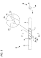
- the electrode 22 is structured in the following manner. That is, as shown in Fig. 3 , the portion of the electrode 22 in the longitudinal direction except for the two end side portions thereof is formed as a portion to be sealed (a sealed portion) 28; the portion of the electrode 22 in the longitudinal direction except for its one end side portion is formed as a projecting portion 29 which is projected into the light emitting portion 20; and, the portion of the electrode 22 in the longitudinal direction except for its other end side portion is formed as a welding portion 30 which is to be welded to the molybdenum foil 23.
- a crack (micro crack) C supposed to be caused by a shape (a concavo-convex part which will be discussed later) formed in the electrode 22 is shown conceptually.
- the sealed portion 28 is sealed to the pinch seal portion 21 of the ceramic arc tube 19.
- the sealed portion 28 includes a groove-shaped concave portion 28a arranged in a spiral manner.
- the other remaining portions of the sealed portion 28 than the concave portion 28a are formed as a convex portion 28b; and, the concave portion 28a and convex portion 28b cooperate together in constituting a concavo-convex part 28c.
- Connecting portions 28d, 28d, ---, where the concave portion 28a and convex portion 28b are connected together, are formed to have a curved surface shape (see the enlarged view of Fig. 3 ).
- a length of the area of the concavo-convex part 28c is set in the range of 1 to 5mm
- a height thereof is set in the range of 1 to 10% of the diameter of the electrode (that is, a height of the convex portion is set within a range of 1 to 10% with respect to a diameter of the projecting portion of the electrode, or a depth of the concave portion is set within a range of 1 to 10% with respect to a diameter of the projecting portion of the electrode)
- the spacing between the recess and convex portions thereof is set in the range of 5 to 50% of the diameter of the electrode.
- the concavo-convex part 28c in a state where a round-shaft-shaped electrode rod is rotated around the axis thereof and is also moved in the axial direction thereof, a laser beam may be radiated onto such electrode rod to thereby be able to form the spiral-shaped concave portion 28a. Therefore, the concavo-convex part 28c including the spiral-shaped concave portion 28a can be produced easily.
- the projecting portion 29 is projected into the light emitting portion 20 but is not sealed to the pinch seal portion 21.
- the welding portion 30 is welded to the molybdenum foil 23 in a state where it is sealed to the pinch seal portion 21.
- the welding portion 30 has no concavo-convex part.
- a stress which can be generated when the discharge lamp 8 is turned on and off, is dispersed by the concave portion 28a and convex portion 28b and thus a crack, which can be produced, is a so called micro crack: that is, a large crack is hard to be produced.
- the electrode 22 includes the sealed portion 28, projecting portion 29 and welding portion 30 and also since the sealed portion 28 includes the concavo-convex part 28c, a stress to be produced in the lamp turn on and off operation is dispersed by the concavo-convex part 28c and thus a large crack is hard to be produced, which can prevent the generation of the leakage of the electrodes.
- the sealed portion 28 is sealed by the pinch seal portion 21, a rare gas and metal halide enclosed into the light emitting portion 20 are prevented from moving into the pinch seal portion 21, which makes it possible to secure the proper turn-on state of the discharge lamp 8.
- the metal halide since the metal halide is prevented from moving into the pinch seal portion 21, the metal halide can be prevented from generating a stress which can peel the molybdenum foil 23 from the pinch seal portion 21. This allows the molybdenum foil 23 to secure a high degree of close contact with respect to the pinch seal portion 21, thereby being able to prevent the sealed portion of the molybdenum foil 23 against leakage (foil leakage).
- the welding portion 30, that is, the portion of the electrode 22 where the concavo-convex part 28c is not formed, is welded to the molybdenum foil 23
- the electrode 22 is welded to the molybdenum foil 23 in a state where it secures a high degree of close contact with respect to the molybdenum foil 23 and thus the electrode 22 is prevented from inclining with respect to the molybdenum foil 23, thereby being able to stabilize the lighting state of the discharge lamp 8.
- portions 28d where the concave portions 28a and convex portions 28b of the electrodes 22 continue with each other are respectively formed to have a curved surface shape, the concentration of stresses can be relieved and thus the production of a crack can be restricted.
- the sealed portion 28A includes groove-shaped concave portions 28a, 28a, --- which respectively extend in the peripheral direction of the sealed portion 28A and are formed spaced from each other in the axial direction of the sealed portion 28A. Therefore, the other remaining portions of the sealed portion 28A than the concave portions 28a, 28a, --- are formed as convex portions 28b, 28b, ---; and, the concave portions 28a, 28a, --- and convex portions 28b, 28b, --- cooperate together in constituting a concavo-convex part 28c.
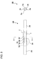
- An electrode 22B according to a second modification, as shown in Fig. 5 includes a sealed portion 28B, a projecting portion 29B and a welding portion 30B.
- the sealed portion 28B includes groove-shaped concave portions 28a, 28a, --- which respectively extend in the peripheral direction of the sealed portion 28B and are formed spaced from each other in the axial direction of the sealed portion 28B. Therefore, the other remaining portions of the sealed portion 28B than the concave portions 28a, 28a, --- are formed as convex portions 28b, 28b, ---; and, the concave portions 28a, 28a, --- and convex portions 28b, 28b, ---cooperate together in constituting a concavo-convex part 28c.
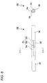
- An electrode 22C according to a third modification, as shown in Fig. 6 includes a sealed portion 28C, a projecting portion 29C and a welding portion 30C.
- the sealed portion 28C includes hole-shaped concave portions 28a, 28a, --- formed such that they are dotted. Therefore, the other remaining portions of the sealed portion 28C than the concave portions 28a, 28a, --- are formed as convex portions 28b, 28b, ---; and, the concave portions 28a, 28a, --- and convex portions 28b, 28b, ---cooperate together in constituting a concavo-convex part 28c.
- An electrode 22D according to a fourth modification, as shown in Fig. 7 includes a sealed portion 28D, a projecting portion 29D and a welding portion 30D.
- the sealed portion 28D includes a slit-shaped concave portion 28a which is formed to extend in the axial direction of the sealed portion 28D.
- the other remaining portion of the sealed portion 28D than the concave portion 28a is formed as a convex portion 28b; and, the concave portion 28a and convex portion 28b cooperate together in constituting a concavo-convex part 28c.
- An electrode 22E according to a fifth modification, as shown in Fig. 8 includes a sealed portion 28E, a projecting portion 29E and a welding portion 30E.
- the sealed portion 28E includes slit-shaped concave portions 28a, 28a which are formed such that they extend in the axial direction of the sealed portion 28E and cross each other perpendicularly.
- the other remaining portion of the sealed portion 28E than the concave portions 28a, 28a is formed as a convex portion 28b; and, the concave portion 28a, 28a and convexportion 28b cooperate together in constituting a concavo-convex part 28c.
- An electrode 22F according to a sixth modification is structured such that, in the electrode 22A according to the first modification, the concave portions and convex portions are formed in the mutually opposite positions. That is, as shown in Fig. 9 , the electrode 22F includes a sealed portion 28F, a projecting portion 29F and a welding portion 30F.
- the sealed portion 28F includes convex portions 28b, 28b, --- which are formed such that they respectively extend in the peripheral direction of the sealed portion 29F and are spaced from each other in the axial direction of the sealedportion 29F.
- the other remaining portions of the sealed portion 28F than the convex portions 28b, 28b, --- are respectively formed as concave portions 28a, 28a, ---; and, the convex portions 28b, 28b, --- and concave portions 28a, 28a, --- cooperate together in constituting a concavo-convex part 28c.
- the convex portions 28b, 28b, --- can be formed by cutting the portions of the electrode 22F that are formed as the concave portions 28a, 28a, ---. Therefore, it is possible to increase the diameter of the projecting portion 29F which is the portion of the electrode 22F that is not cut. By increasing the diameter of the projecting portion 29F, the electrode 22F is able to cope with the load of a current value when the current value is set for a high value in order to secure a high tube voltage.
Landscapes
- Vessels And Coating Films For Discharge Lamps (AREA)
Abstract
Description
- The present invention relates to a discharge lamp for use in a vehicle. Specifically, the invention relates to a vehicle discharge lamp, in which a concavo-convex part including a concave portion and a convex portion is formed on a portion of an electrode sealed in a pinch seal portion of an arc tube, to thereby restrict a generation of a crack and thus prevent a generation of a leakage at the electrode.
- As a headlamp for use in an vehicle, for example, there are known a headlamp of a type using an incandescent lamp (an incandescent bulb) or a halogen lamp (a halogen bulb) as its light source, a headlamp of a type using a discharge lamp (a discharge bulb) as its light source, or a headlamp of a type using a light emitting diode (LED) as its light source.
- Referring to the vehicle headlamp using the discharge lamp as its light source, since the discharge lamp is larger in an amount of light and is higher in a radiance than the incandescent lamp, halogen lamp and light emitting diode, the vehicle headlamp using the discharge lamp has an advantage that it can realize a headlamp having a large light amount.
- The discharge lamp has a double tube structure in which an arc tube holding a pair of electrodes and containing a gas such as a rare gas and a metal halide enclosed therein is disposed within an outer tube. The arc tube includes a light emitting portion and a pair of pinch seal portions which are made of quartz glass or the like. Discharge is carried out in an interior portion of the light emitting portion, while the two pinch seal portions are respectively disposed on the mutually opposite sides with the light emitting portion between them. The light emitting portion is shielded from an outside by the pinch seal portions. The light emitting portion is a portion where, when discharge is carried out, there is generated arc; and, it is formed larger in diameter than the pinch seal portions.
- One-end portions of the pair of electrodes are respectively projected into the interior portion of the light emitting portion, while the other remaining portions thereof are respectively sealed to the pair of pinch seal portions. The other end portions of the pair of electrodes are welded to their corresponding molybdenum foils which are respectively sealed to their corresponding pinch seal portions.
- In the discharge lamp, a given starting voltage is applied to the pair of electrodes held by the arc tube and discharge is carried out in the light emitting portion of the arc tube, thereby starting a turn-on operation of the discharge lamp.
- In such discharge lamp, the arc tube is pinch sealed by the molybdenum foils in order to completely shield the arc tube from the outside.
- Each of the molybdenum foils is formed in a very thin foil in order to minimize a stress which is generated due to a difference in coefficients of thermal expansion between it and the quarts glass of the pinch seal portions, while such difference depends on variations in temperature which are caused by repetitively turning on and off the discharge lamp.
- However, when the discharge lamp is repetitively turned on and off in tens thousands times, a stress gradually causes the molybdenum foil and quartz glass to peel off from each other (to produce a crack), and, finally resulting in a lighting failure of the discharge lamp due to a leakage (that is, the discharge lamp comes to the end of its life).
- As a method for preventing such discharge lamp lighting failure and thus for extending the life of the discharge lamp, two main methods may be considered: that is,
- (1) : a method for enhancing a degree of close contact between the molybdenum foil and the quartz glass.
- (2): a method for separating the molybdenum foil from the light emitting portion, namely, increasing a length of the electrode.
- However, in the (1) method for enhancing the degree of close contact between the molybdenum foil and quartz glass, since the close contact between the electrode and quartz glass is also enhanced, when the temperature is caused to vary due to the repetitive turn-on/off operations of the discharge lamp; and, such variations in the temperature give rise to a difference in the coefficients of thermal expansion between the electrode and pinch seal portion, a stress is generated as a result. This stress raises a possibility that a crack can be produced in the pinch seal portion existing around the electrode, whereby the lighting failure of the discharge lamp due to the leakage may be occurred.
- Recently, due to environmental concerns, there has been increasing use of a discharge lamp of a type in which no mercury is enclosed into an arc tube. In such discharge lamp, since no mercury is enclosed in the arc tube, a voltage of the arc tube does not rise. As a result, a current of the arc tube becomes large. In order to correspond to such large arc tube current, outside diameters of the electrodes are set large.
Due to this, the stress between the electrodes and pinch seal portions is intensified, thereby increasing the possibility that the crack can be generated in the pinch seal portions.
Such crack can cause the leakage, thereby facilitating the occurrence of the lighting failure of the discharge lamp. - On the other hand, when the degree of close contact between the molybdenum foil and quarts glass is lowered, not only the life of the discharge lamp is shortened but also there can be generated a clearance between the electrode and quartz glass, which can also raise a possibility of causing the lighting failure of the discharge lamp due to the leakage.
- Also, in the (2) method for separating the molybdenum foil from the light emitting portion, namely, increasing the length of the electrode, since the length of the close contact area between the electrode and quartz glass is increased, there is increased the stress which is generated between the electrode and pinch seal portion, and thus there is produced a crack in the pinch seal portion existing around the electrode. As a result of this, the leakage may be easy occurred, thereby facilitating the occurrence of the lighting failure of the discharge lamp due to the leakage.
- In order to prevent the occurrence of the leakage due to the above crack, as a conventional discharge lamp, there is known a discharge lamp in which, in the other remaining portion of each electrode than such portion thereof as is projected into the light emitting portion, there is formed a concavo-convex part including a concave portion and a convex portion, and the electrodes are respectively welded to corresponding molybdenum foils in a state where given clearances are respectively formed between the electrodes and pinch seal portions (for example, see
JP-A-2002-373622 - In the discharge lamp disclosed in
JP-A-2002-373622 - However, in the discharge lamp disclosed in
JP-A-2002-373622 - Also, since there is formed the clearance between the electrode and pinch seal portion and the molybdenum foil is sealed to such portion of the pinch seal portion as continues with the clearance, due to the high pressure that is generated while the discharge lamp is lighted, an iodide is allowed to move from the clearance to the molybdenum foil in a gaseous state. When the gaseous iodide arrives at the molybdenum foil, owing to the fact that the iodide is set up when the discharge lamp is turned off, there is generated a stress that peels the molybdenum foil from the pinch seal portion to lower the degree of close contact between the pinch seal portion and molybdenum foil, whereby the leakage is occurred in the vicinity of the molybdenum foil sealed portion of the pinch seal portion (foil leakage). This gives rise to the lighting failure of the discharge lamp, resulting in the shortened life of the discharge lamp.
- Further, in the discharge lamp disclosed in
JP-A-2002-373622 - One or more embodiment of the present invention provide a vehicle discharge lamp which can restrict a generation of a crack to thereby prevent a leakage at an electrode or the like.
- In accordance with one or more embodiments of the invention, a vehicle discharge lamp is provided with: an outer tube; an arc tube disposed within the outer tube and made of quartz glass, wherein no mercury is enclosed within the arc tube; and a pair of electrodes respectively disposed within the arc tube. The arc tube includes: a light emitting portion, wherein a rare gas and a metal halide are enclosed within the light emitting portion; and a pair of pinch seal portions respectively formed continuously with the light emitting portion on both sides of the light emitting portion, wherein molybdenum foils are respectively sealed in the pair of pinch seal portions.
Each of the electrodes includes: a sealed portion sealed within corresponding one of the pinch seal portions; a projecting portion formed continuously with one end of the sealed portion and projecting into the light emitting portion; and a welding portion formed continuously with the other end of the sealed portion and welded to corresponding one of molybdenum foils. A concavo-convex part including a concave portion and a convex portion is formed on the sealed portion. - According to this structure, the concavo-convex part formed in the electrode is sealed within the pinch seal portion and the welding portion of the electrode, where no concavo-convex part is formed, is welded to the molybdenum foil.
- According to this structure, since a stress to be generated when turning on and off the discharge lamp is dispersed by the concavo-convex parts to thereby make it hard for a large crack to occur, it is possible to prevent the leakage at the electrodes.
- In the above structure, the concave portion may be formed in a spiral shape. According to this structure, it is easy to manufacture the electrode that includes a concavo-convex part.
- In the above structure, the concave portion may include multiple concaves which are spaced from each other. According to this structure, a stress to be generated when turning on and off the discharge lamp can be easily dispersed by the recess and convex portions. This can provide an effect of restricting the generation of the crack.
- In the above structure, a portion, where the concave portion and convex portion are continuously connected to each other, is formed in a curved surface shape. According to this structure, a concentration of stresses can be relieved and thus the generation of the crack can be restricted.
- Other aspects and advantages of the invention will be apparent from the following description, the drawings and the claims.
-
-
Fig. 1 is a schematic section view of a vehicle discharge lamp of an exemplary embodiment of the invention. -
Fig. 2 is enlarged side view, partially in section, of the discharge lamp. -
Fig. 3 is an enlarged side view of an electrode and an enlarged section view thereof. -
Fig. 4 is an enlarged side view of an electrode according to a first modification and an enlarged section view thereof. -
Fig. 5 is an enlarged side view of an electrode according to a second modification and an enlarged section view thereof. -
Fig. 6 is an enlarged side view of an electrode according to a third modification and an enlarged section view thereof. -
Fig. 7 is an enlarged side view of an electrode according to a fourth modification and an enlarged section view thereof. -
Fig. 8 is an enlarged side view of an electrode according to a fifth modification and an enlarged section view thereof. -
Fig. 9 is an enlarged side view of an electrode according to a sixth modification and an enlarged section view thereof. - Detailed description of exemplary embodiments of the invention will be given with reference to the accompanying drawings. In the exemplary embodiments, the vehicle discharge lamp is mounted on a vehicle headlamp.
- A
vehicle headlamp 1 is mounted on right and left end portions of a front end portion of a vehicle body. - The
vehicle headlamp 1, as shown inFig. 1 , includes alamp housing 2 having a forwardly opened recessed portion and acover 3 for covering the opened surface of thelamp housing 2. Thelamp housing 2 andcover 3 cooperate together in forming a lamp casing 4. The inner space of the lamp casing 4 is formed as alamp chamber 5. - In a rear end portion of the
lamp housing 2, there is formed aninsertion hole 2a which penetrates back and forth through the rear end portion, while theinsertion hole 2a is closed by aback cover 6. In a lower end portion of thelamp housing 2, there is formed adisposition hole 2b which penetrates vertically through the lower end portion. - Within the
lamp chamber 5, a reflector 7 is supported by an optical axis adjusting mechanism (not shown) in such a manner that it can be inclined. In a rear end portion of the reflector 7, there is formed a mountinghole 7a which penetrates back and forth through the rear end portion. - On the mounting
hole 7a of the reflector 7, there is mounted a discharge lamp (vehicle discharge lamp) 8. - On the
disposition hole 2b of thelamp housing 2, there is mounted a discharge lamp lighting device 9. To form the discharge lamp lighting device 9, a lighting circuit (not shown) may be stored within acase member 10. On the outer peripheral surface of thecase member 10, there is provided aninput side connector 11 and, on the upper surface of thecase member 10, there is provided anoutput side connector 12. Theinput side connector 11 is connected to a power supply circuit (not shown). - The
output side connector 12 is connected through afeed cable 13 to astarter device 14, while theconnector 14a of thestarter device 14 is connected to a socket (which will be discussed later) included in the discharge lamp 8. - To turn on the discharge lamp 8, the line voltage of the power supply circuit may be increased using the lighting circuit of the discharge lamp lighting device 9 and also may be d/c converted to thereby provide a lighting voltage (starting voltage) which is a high ac voltage; and, this lighting voltage may be applied through the
feed cable 13 andstarter device 14 to the discharge lamp 8 to thereby start discharge in the discharge lamp 8. - Within the
lamp chamber 5, there is provided anextension 15 which is used to shield some of composing parts disposed in thelamp chamber 5. Within thelamp chamber 5, there is further provided a shade (not shown) which is used to shield a portion of the light that is emitted from the discharge lamp 8. - The discharge lamp 8 is structured by connecting a
main body 16 to a socket 17 (seeFig. 2 ). - The
main body 16 includes anouter tube 18 and anarc tube 19 disposed within theouter tube 18, while theouter tube 18 andarc tube 19 are made of quartz glass as an integral body. - The
outer tube 18 includes aclosing portion 18a for covering thearc tube 19 or the like and a holdingportion 18b projected from the front end portion of the closingportion 18a. - The
arc tube 19 includes, for example, alight emitting portion 20 having an inner space of 22 µl and an inside diameter of 2.6 mm, and twopinch seal portions light emitting portion 20. Thepinch seal portions pinch seal portions 21 are set smaller than the outside diameter of thelight emitting portion 20. - Into the
light emitting portion 20, there are enclosed 0.3 mg of metal halide, for example, NaI, ScI3, ScBr3, InI, and ZnI2 with the enclosure ratio (weight %) of 58; 12.8; 20; 0.2; and 9, and also, as a rare gas, Xe with the pressure of 15.5 pressures. Here, no mercury is enclosed in thelight emitting portion 20. - The pinch seals 21 and 21 respectively hold thereon
electrodes electrode 22 includes, for example, 0.1% of sodium oxide, and has a diameter of 0.3 mm to 0.4 mm and the whole length of 6 to 8 mm. The twoelectrodes - To the
pinch seal portions electrodes - To the front end portion of the
molybdenum foil 23 that is situated on the front side, there is connected afirst lead wire 24. Thefirst lead wire 24 is projected forwardly from the front sidepinch seal portion 21 of thearc tube 19, is penetrated through the holdingportion 18b and is projected outwardly of theouter tube 18, while the thus outwardly projected portion of thefirst lead wire 24 is used as a connectingportion 24a. The connectingportion 24a of thefirst lead wire 24 is welded and connected to anexternal lead wire 25. - The
external lead wire 25 includes avertical portion 25a extending in the vertical direction and ahorizontal portion 25b which is formed continuously with the lower end of thevertical portion 25a and extends in the longitudinal direction of thelead wire 25. The upper end portion of thevertical portion 25a is connected to the connectingportion 24a of thefirst lead wire 24, while the rear end portion of thehorizontal portion 25b is connected to a first connecting terminal (not shown) which is provided in thesocket 17. - The
horizontal portion 25b of theexternal lead wire 25 is covered with an insulatingsleeve 26. The insulatingsleeve 26 is made of insulating material, for example, glass or ceramic. - To the rear end portion of the
molybdenum foil 23 that is situated on the rear side, there is connected asecond lead wire 27 which extends in the back-and-forth direction. Thesecond lead wire 27 is projected backwardly from the rear sidepinch seal portion 21 of thearc tube 19. The rear end portion of thesecond lead wire 27 is connected to a second connecting terminal (not shown) which is provided in thesocket 17. - The
electrode 22 is structured in the following manner. That is, as shown inFig. 3 , the portion of theelectrode 22 in the longitudinal direction except for the two end side portions thereof is formed as a portion to be sealed (a sealed portion) 28; the portion of theelectrode 22 in the longitudinal direction except for its one end side portion is formed as a projectingportion 29 which is projected into thelight emitting portion 20; and, the portion of theelectrode 22 in the longitudinal direction except for its other end side portion is formed as awelding portion 30 which is to be welded to themolybdenum foil 23. - Here, in
Figs. 3 and its following figures, the side view of the electrode is shown on the left, while the section view taken along the section support lines S, S of the side view of the electrode is shown on the right. Also, inFigs. 3 and its following figures, the shape of a crack (micro crack) C supposed to be caused by a shape (a concavo-convex part which will be discussed later) formed in theelectrode 22 is shown conceptually. - The sealed
portion 28 is sealed to thepinch seal portion 21 of theceramic arc tube 19. The sealedportion 28 includes a groove-shapedconcave portion 28a arranged in a spiral manner.
Thus, the other remaining portions of the sealedportion 28 than theconcave portion 28a are formed as aconvex portion 28b; and, theconcave portion 28a andconvex portion 28b cooperate together in constituting a concavo-convex part 28c. - Connecting
portions concave portion 28a andconvex portion 28b are connected together, are formed to have a curved surface shape (see the enlarged view ofFig. 3 ). - Referring to the structure of the concavo-
convex part 28c, for example, a length of the area of the concavo-convex part 28c is set in the range of 1 to 5mm, a height thereof is set in the range of 1 to 10% of the diameter of the electrode (that is, a height of the convex portion is set within a range of 1 to 10% with respect to a diameter of the projecting portion of the electrode, or a depth of the concave portion is set within a range of 1 to 10% with respect to a diameter of the projecting portion of the electrode), and the spacing between the recess and convex portions thereof is set in the range of 5 to 50% of the diameter of the electrode. To produce the concavo-convex part 28c, in a state where a round-shaft-shaped electrode rod is rotated around the axis thereof and is also moved in the axial direction thereof, a laser beam may be radiated onto such electrode rod to thereby be able to form the spiral-shapedconcave portion 28a. Therefore, the concavo-convex part 28c including the spiral-shapedconcave portion 28a can be produced easily. - The projecting
portion 29 is projected into thelight emitting portion 20 but is not sealed to thepinch seal portion 21. - The
welding portion 30 is welded to themolybdenum foil 23 in a state where it is sealed to thepinch seal portion 21. Thewelding portion 30 has no concavo-convex part. - Since the
electrode 22 is structured in the above-mentioned manner and also since the concavo-convex part 28c is formed in the sealedportion 28, a stress, which can be generated when the discharge lamp 8 is turned on and off, is dispersed by theconcave portion 28a andconvex portion 28b and thus a crack, which can be produced, is a so called micro crack: that is, a large crack is hard to be produced. - As described hereinabove, in the discharge lamp 8, since the
electrode 22 includes the sealedportion 28, projectingportion 29 andwelding portion 30 and also since the sealedportion 28 includes the concavo-convex part 28c, a stress to be produced in the lamp turn on and off operation is dispersed by the concavo-convex part 28c and thus a large crack is hard to be produced, which can prevent the generation of the leakage of the electrodes. - Also, since the sealed
portion 28 is sealed by thepinch seal portion 21, a rare gas and metal halide enclosed into thelight emitting portion 20 are prevented from moving into thepinch seal portion 21, which makes it possible to secure the proper turn-on state of the discharge lamp 8. - Further, since the metal halide is prevented from moving into the
pinch seal portion 21, the metal halide can be prevented from generating a stress which can peel themolybdenum foil 23 from thepinch seal portion 21. This allows themolybdenum foil 23 to secure a high degree of close contact with respect to thepinch seal portion 21, thereby being able to prevent the sealed portion of themolybdenum foil 23 against leakage (foil leakage). - Moreover, in the discharge lamp 8, since the
welding portion 30, that is, the portion of theelectrode 22 where the concavo-convex part 28c is not formed, is welded to themolybdenum foil 23, theelectrode 22 is welded to themolybdenum foil 23 in a state where it secures a high degree of close contact with respect to themolybdenum foil 23 and thus theelectrode 22 is prevented from inclining with respect to themolybdenum foil 23, thereby being able to stabilize the lighting state of the discharge lamp 8. - In addition, since the
portions 28d where theconcave portions 28a andconvex portions 28b of theelectrodes 22 continue with each other are respectively formed to have a curved surface shape, the concentration of stresses can be relieved and thus the production of a crack can be restricted. - Now, description will be given below of modifications of the electrode (see
Figs. 4 to 9 ). - An
electrode 22A according to a first modification, as shown inFig. 4 , includes a sealedportion 28A, a projectingportion 29A and awelding portion 30A. The sealedportion 28A includes groove-shapedconcave portions portion 28A and are formed spaced from each other in the axial direction of the sealedportion 28A. Therefore, the other remaining portions of the sealedportion 28A than theconcave portions convex portions concave portions convex portions convex part 28c. - An
electrode 22B according to a second modification, as shown inFig. 5 , includes a sealedportion 28B, a projectingportion 29B and awelding portion 30B. The sealedportion 28B includes groove-shapedconcave portions portion 28B and are formed spaced from each other in the axial direction of the sealedportion 28B. Therefore, the other remaining portions of the sealedportion 28B than theconcave portions convex portions concave portions convex portions convex part 28c. - An
electrode 22C according to a third modification, as shown inFig. 6 , includes a sealedportion 28C, a projectingportion 29C and awelding portion 30C. The sealedportion 28C includes hole-shapedconcave portions portion 28C than theconcave portions convex portions concave portions convex portions convex part 28c. - In the
electrodes concave portions concave portions convex portions - An
electrode 22D according to a fourth modification, as shown inFig. 7 , includes a sealedportion 28D, a projectingportion 29D and awelding portion 30D. The sealedportion 28D includes a slit-shapedconcave portion 28a which is formed to extend in the axial direction of the sealedportion 28D.
The other remaining portion of the sealedportion 28D than theconcave portion 28a is formed as aconvex portion 28b; and, theconcave portion 28a andconvex portion 28b cooperate together in constituting a concavo-convex part 28c. - An
electrode 22E according to a fifth modification, as shown inFig. 8 , includes a sealedportion 28E, a projectingportion 29E and awelding portion 30E. The sealedportion 28E includes slit-shapedconcave portions portion 28E and cross each other perpendicularly. The other remaining portion of the sealedportion 28E than theconcave portions convex portion 28b; and, theconcave portion convexportion 28b cooperate together in constituting a concavo-convex part 28c. - An
electrode 22F according to a sixth modification is structured such that, in theelectrode 22A according to the first modification, the concave portions and convex portions are formed in the mutually opposite positions. That is, as shown inFig. 9 , theelectrode 22F includes a sealedportion 28F, a projectingportion 29F and awelding portion 30F. The sealedportion 28F includesconvex portions portion 29F and are spaced from each other in the axial direction of thesealedportion 29F. Therefore, the other remaining portions of the sealedportion 28F than theconvex portions concave portions convex portions concave portions convex part 28c. - In the
electrode 22F, for example, theconvex portions electrode 22F that are formed as theconcave portions portion 29F which is the portion of theelectrode 22F that is not cut. By increasing the diameter of the projectingportion 29F, theelectrode 22F is able to cope with the load of a current value when the current value is set for a high value in order to secure a high tube voltage. - Here, in the above description, as an example of a structure in which the concave portion and convex portion are formed at their mutual opposite positions, there was illustrated the
electrode 22F according to the sixth modification. However, in the second to fifth modifications as well, it is also possible to form an electrode having a structure in which the concave portion and convex portion are formed at their mutual opposite positions. - While description has been made in connection with a specific exemplary embodiment of the present invention and specific modifications thereof, it will be obvious to those skilled in the art that various changes and modification may be made therein without departing from the present invention. It is aimed, therefore, to cover in the appended claims all such changes and modifications falling within the true spirit and scope of the present invention.
-
- 8:
- Discharge lamp (vehicle discharge lamp)
- 18:
- Outer tube
- 19:
- Arc tube
- 20:
- Light emitting portion
- 21:
- Pinch seal portion
- 22:
- Electrode
- 23:
- Molybdenum foil
- 28:
- Sealed portion
- 28a:
- Concave portion
- 28b:
- Convex portion
- 28c:
- Concavo-convex part
- 28d:
- Portion
- 29:
- Projecting portion
- 30:
- Welding portion
- 22A:
- Electrode
- 22B:
- Electrode
- 22C:
- Electrode
- 22D:
- Electrode
- 22E:
- Electrode
- 22F:
- Electrode
Claims (6)
- A vehicle discharge lamp (8) comprising:an outer tube (18);an arc tube (19) disposed within the outer tube (18) and made of quartz glass, wherein no mercury is enclosed within the arc tube (19); anda pair of electrodes (22, 22A, 22B, 22C, 22D, 22E, 22F) respectively disposed within the arc tube (19),wherein the arc tube (19) includes:a light emitting portion (20), wherein a rare gas and a metal halide are enclosed within the light emitting portion (20); anda pair of pinch seal portions (21) respectively formed continuously with the light emitting portion (20) on both sides of the light emitting portion (20), wherein molybdenum foils (23) are respectively sealed in the pair of pinch seal portions (21),wherein each of the electrodes (22, 22A, 22B, 22C, 22D, 22E, 22F) includes:a sealed portion (28, 28A, 28B, 28C, 28D, 28E, 28F) sealed within corresponding one of the pinch seal portions (21);a projecting portion (29, 29A, 29B, 29C, 29D, 29E, 29F) formed continuously with one end of the sealed portion (28, 28A, 28B, 28C, 28D, 28E, 28F) and projecting into the light emitting portion (20); anda welding portion (30, 30A, 30B, 30C, 30D, 30E, 30F) formed continuously with the other end of the sealed portion (28, 28A, 28B, 28C, 28D, 28E, 28F) and welded to corresponding one of the molybdenum foils (23), andwherein a concavo-convex part (28c) including a concave portion (28a) and a convex portion (28b) is formed on the sealed portion (28, 28A, 28B, 28C, 28D, 28E, 28F).
- The vehicle discharge lamp according to Claim 1, wherein the concave portion (28a) is formed in a spiral shape.
- The vehicle discharge lamp according to Claim 1, wherein the concave portion (28a) includes multiple concaves (28a) which are spaced from each other.
- The vehicle discharge lamp according to any one of Claims 1 to 3, wherein a portion (28d), where the concave portion (28a) and convex portion (28b) are continuously connected to each other, is formed in a curved surface shape.
- The vehicle discharge lamp according to any one of Claims 1 to 4, wherein a height of the convex portion (28b) is set within a range of 1 to 10% with respect to a diameter of the projecting portion (29, 29A, 29B, 29C, 29D, 29E, 29F) of the electrode.
- The vehicle discharge lamp according to any one of Claims 1 to 4, wherein a depth of the concave portion (28a) is set within a range of 1 to 10% with respect to a diameter of the projecting portion (29, 29A, 29B, 29C, 29D, 29E, 29F) of the electrode.
Applications Claiming Priority (1)
| Application Number | Priority Date | Filing Date | Title |
|---|---|---|---|
| JP2009122318A JP2010272307A (en) | 2009-05-20 | 2009-05-20 | Discharge lamp for vehicle |
Publications (2)
| Publication Number | Publication Date |
|---|---|
| EP2254144A2 true EP2254144A2 (en) | 2010-11-24 |
| EP2254144A3 EP2254144A3 (en) | 2011-06-08 |
Family
ID=42668266
Family Applications (1)
| Application Number | Title | Priority Date | Filing Date |
|---|---|---|---|
| EP10163138A Withdrawn EP2254144A3 (en) | 2009-05-20 | 2010-05-18 | Vehicle discharge lamp |
Country Status (3)
| Country | Link |
|---|---|
| US (1) | US20100295448A1 (en) |
| EP (1) | EP2254144A3 (en) |
| JP (1) | JP2010272307A (en) |
Cited By (1)
| Publication number | Priority date | Publication date | Assignee | Title |
|---|---|---|---|---|
| WO2011073862A1 (en) * | 2009-12-18 | 2011-06-23 | Koninklijke Philips Electronics N.V. | An electrode for use in a lamp |
Families Citing this family (3)
| Publication number | Priority date | Publication date | Assignee | Title |
|---|---|---|---|---|
| JP4730445B2 (en) * | 2009-02-09 | 2011-07-20 | ウシオ電機株式会社 | High pressure discharge lamp |
| JP4760945B2 (en) * | 2009-04-17 | 2011-08-31 | 岩崎電気株式会社 | Light source device |
| US9093256B2 (en) * | 2011-09-30 | 2015-07-28 | Koninklijke Philips N.V. | Discharge lamp |
Citations (1)
| Publication number | Priority date | Publication date | Assignee | Title |
|---|---|---|---|---|
| JP2002373622A (en) | 2001-06-13 | 2002-12-26 | Ushio Inc | Short arc type ultra-high pressure discharge lamp |
Family Cites Families (14)
| Publication number | Priority date | Publication date | Assignee | Title |
|---|---|---|---|---|
| US5404078A (en) * | 1991-08-20 | 1995-04-04 | Patent-Treuhand-Gesellschaft Fur Elektrische Gluhlampen Mbh | High-pressure discharge lamp and method of manufacture |
| JPH05198284A (en) * | 1991-09-30 | 1993-08-06 | Toshiba Lighting & Technol Corp | Metal halide lamp |
| JPH10241630A (en) * | 1997-02-24 | 1998-09-11 | Matsushita Electron Corp | Lamp |
| JP3204189B2 (en) * | 1997-12-08 | 2001-09-04 | ウシオ電機株式会社 | Short arc type ultra-high pressure discharge lamp |
| JP3586607B2 (en) * | 1999-12-28 | 2004-11-10 | Necマイクロ波管株式会社 | High pressure discharge lamp |
| JP4413702B2 (en) * | 2004-07-30 | 2010-02-10 | ハリソン東芝ライティング株式会社 | Metal halide lamp |
| KR20070100416A (en) * | 2005-02-04 | 2007-10-10 | 코닌클리즈케 필립스 일렉트로닉스 엔.브이. | Lamps with electrodes and quartz bulbs with longitudinal grooves |
| DE102005013759A1 (en) * | 2005-03-22 | 2006-09-28 | Patent-Treuhand-Gesellschaft für elektrische Glühlampen mbH | Lamp with power supply and electrode |
| JP4618793B2 (en) * | 2005-05-31 | 2011-01-26 | 株式会社小糸製作所 | Mercury-free arc tube for discharge bulb |
| US7952283B2 (en) * | 2005-11-09 | 2011-05-31 | General Electric Company | High intensity discharge lamp with improved crack control and method of manufacture |
| JP5519280B2 (en) * | 2006-09-12 | 2014-06-11 | コーニンクレッカ フィリップス エヌ ヴェ | Lamp with conductor embedded in the envelope of the quartz glass of the lamp |
| WO2008119375A1 (en) * | 2007-03-29 | 2008-10-09 | Patent-Treuhand-Gesellschaft für elektrische Glühlampen mbH | Discharge lamp, particularly high-pressure discharge lamp |
| JP4862739B2 (en) * | 2007-05-08 | 2012-01-25 | ウシオ電機株式会社 | Electrode for ultra high pressure discharge lamp and ultra high pressure discharge lamp |
| JP2010541129A (en) * | 2007-09-24 | 2010-12-24 | コーニンクレッカ フィリップス エレクトロニクス エヌ ヴィ | Discharge lamp without thorium |
-
2009
- 2009-05-20 JP JP2009122318A patent/JP2010272307A/en active Pending
-
2010
- 2010-05-18 EP EP10163138A patent/EP2254144A3/en not_active Withdrawn
- 2010-05-18 US US12/782,069 patent/US20100295448A1/en not_active Abandoned
Patent Citations (1)
| Publication number | Priority date | Publication date | Assignee | Title |
|---|---|---|---|---|
| JP2002373622A (en) | 2001-06-13 | 2002-12-26 | Ushio Inc | Short arc type ultra-high pressure discharge lamp |
Cited By (2)
| Publication number | Priority date | Publication date | Assignee | Title |
|---|---|---|---|---|
| WO2011073862A1 (en) * | 2009-12-18 | 2011-06-23 | Koninklijke Philips Electronics N.V. | An electrode for use in a lamp |
| US9653280B2 (en) | 2009-12-18 | 2017-05-16 | Koninklijke Philips N.V. | Electrode for use in a lamp |
Also Published As
| Publication number | Publication date |
|---|---|
| US20100295448A1 (en) | 2010-11-25 |
| EP2254144A3 (en) | 2011-06-08 |
| JP2010272307A (en) | 2010-12-02 |
Similar Documents
| Publication | Publication Date | Title |
|---|---|---|
| CN101490800B (en) | Gas-discharge lamp and method for manufacturing gas-discharge lamp | |
| JP2003168391A (en) | Mercury-free arc tube for discharge lamp device | |
| US20100295448A1 (en) | Vehicle discharge lamp | |
| CN101523550A (en) | Lamps comprising conductors embedded in lamp quartz glass envelopes | |
| JP5201845B2 (en) | High pressure discharge lamp | |
| CN101075548B (en) | Flash discharge lamp | |
| US7301283B1 (en) | Starting aid for low wattage metal halide lamps | |
| US11508568B2 (en) | Excimer lamp | |
| EP2254143B1 (en) | Vehicular discharge lamp | |
| JP4431174B2 (en) | High pressure gas discharge lamp | |
| CN101432842B (en) | Lamp | |
| CN104303261A (en) | Excimer lamp | |
| US7973479B2 (en) | Discharge lamp | |
| EP2461349B1 (en) | Vehicle discharge lamp | |
| JP2009129675A (en) | Discharge lamp for vehicle | |
| CN102918627A (en) | Discharge chamber for high intensity discharge lamp | |
| JPH10284002A (en) | Ceramic discharge lamp, lamp device and lighting device | |
| JP5909994B2 (en) | Ceramic metal halide lamp | |
| JP6562298B2 (en) | Discharge lamp | |
| KR20130058606A (en) | Ceramic metal halide lamp | |
| CN102906854A (en) | Compact metal halide lamp with salt pool container at its arc tube endparts | |
| JP2010225527A (en) | Ceramic metal halide lamp | |
| WO2011045696A2 (en) | Discharge lamp with distortion reduced discharge vessel | |
| US20080238322A1 (en) | Structural unit for an electric lamp with an outer bulb | |
| JP2005190742A (en) | Metal vapor discharge lamp and lighting device |
Legal Events
| Date | Code | Title | Description |
|---|---|---|---|
| PUAI | Public reference made under article 153(3) epc to a published international application that has entered the european phase |
Free format text: ORIGINAL CODE: 0009012 |
|
| 17P | Request for examination filed |
Effective date: 20100518 |
|
| AK | Designated contracting states |
Kind code of ref document: A2 Designated state(s): AL AT BE BG CH CY CZ DE DK EE ES FI FR GB GR HR HU IE IS IT LI LT LU LV MC MK MT NL NO PL PT RO SE SI SK SM TR |
|
| AX | Request for extension of the european patent |
Extension state: BA ME RS |
|
| PUAL | Search report despatched |
Free format text: ORIGINAL CODE: 0009013 |
|
| AK | Designated contracting states |
Kind code of ref document: A3 Designated state(s): AL AT BE BG CH CY CZ DE DK EE ES FI FR GB GR HR HU IE IS IT LI LT LU LV MC MK MT NL NO PL PT RO SE SI SK SM TR |
|
| AX | Request for extension of the european patent |
Extension state: BA ME RS |
|
| STAA | Information on the status of an ep patent application or granted ep patent |
Free format text: STATUS: THE APPLICATION HAS BEEN WITHDRAWN |
|
| 18W | Application withdrawn |
Effective date: 20111108 |