EP2254041A1 - Cordic operational circuit and method - Google Patents
Cordic operational circuit and method Download PDFInfo
- Publication number
- EP2254041A1 EP2254041A1 EP09717736A EP09717736A EP2254041A1 EP 2254041 A1 EP2254041 A1 EP 2254041A1 EP 09717736 A EP09717736 A EP 09717736A EP 09717736 A EP09717736 A EP 09717736A EP 2254041 A1 EP2254041 A1 EP 2254041A1
- Authority
- EP
- European Patent Office
- Prior art keywords
- scale correction
- path
- fine
- rough
- rotation
- Prior art date
- Legal status (The legal status is an assumption and is not a legal conclusion. Google has not performed a legal analysis and makes no representation as to the accuracy of the status listed.)
- Granted
Links
Images
Classifications
-
- G—PHYSICS
- G06—COMPUTING OR CALCULATING; COUNTING
- G06F—ELECTRIC DIGITAL DATA PROCESSING
- G06F7/00—Methods or arrangements for processing data by operating upon the order or content of the data handled
- G06F7/38—Methods or arrangements for performing computations using exclusively denominational number representation, e.g. using binary, ternary, decimal representation
- G06F7/48—Methods or arrangements for performing computations using exclusively denominational number representation, e.g. using binary, ternary, decimal representation using non-contact-making devices, e.g. tube, solid state device; using unspecified devices
- G06F7/544—Methods or arrangements for performing computations using exclusively denominational number representation, e.g. using binary, ternary, decimal representation using non-contact-making devices, e.g. tube, solid state device; using unspecified devices for evaluating functions by calculation
- G06F7/5446—Methods or arrangements for performing computations using exclusively denominational number representation, e.g. using binary, ternary, decimal representation using non-contact-making devices, e.g. tube, solid state device; using unspecified devices for evaluating functions by calculation using crossaddition algorithms, e.g. CORDIC
-
- G—PHYSICS
- G06—COMPUTING OR CALCULATING; COUNTING
- G06T—IMAGE DATA PROCESSING OR GENERATION, IN GENERAL
- G06T3/00—Geometric image transformations in the plane of the image
- G06T3/60—Rotation of whole images or parts thereof
- G06T3/604—Rotation of whole images or parts thereof using coordinate rotation digital computer [CORDIC] devices
Definitions
- the present invention relates to a Coordinate Rotation Digital Computer (referred to as CORDIC) operational circuit, and in particular, to a linear approximation CORDIC operational circuit and method.
- CORDIC Coordinate Rotation Digital Computer
- a CORDIC Coordinat Rotation Digital Computer
- the CORDIC algorithm is an iterative solving method that takes a function as vector rotation on a two-dimensional plane, and finds a true value by iteratively computing vector rotation of a predetermined basic rotational angle.
- n is the number of iterations. Furthermore, ⁇ j ⁇ ⁇ 1,-1 ⁇
- a vector [x(n), y(n)]' implementing a rotation of a rotational angle ⁇ with respect to a vector [x(0), y(0)]' is represented by Expressions (2) and (3).
- K n is a scaling coefficient
- Rotation according to the CORDIC algorithm is pseudo-rotation that accompanies scaling. In order to correct the scaling, it is necessary to perform processing indicated in Expression (4).
- the CORDIC algorithm realizes a rotation operation of the rotational angle ⁇ as a combination of basic rotation of angle ⁇ j.
- the CORDIC algorithm has 2 modes: a Rotation mode and a Vector mode, according to a method of determining the rotation direction parameter ⁇ j given in Expression (6).
- a process is performed to rotate the vector up to an x axis, and to obtain a rotational angle (z(n)) thereof and the norm (x(n)) of the initial vector.
- g is the number of MSB (Most Significant Bit) guard bits for an overflow strategy
- m is the number of LSB (Least Significant Bit) guard bits in a rounding error strategy.
- the linear approximation CORDIC shortens processing delay by performing multiplication in which speeding up is possible using a parallel structure, instead of shift addition/subtraction iterative processing in a later stage of the original CORDIC algorithm.
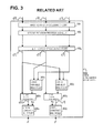
- Fig. 3 is a diagram showing a typical structure of a linear approximation CORDIC circuit (Rotation mode) in first related technology.
- the first related technology as in Fig. 3 is referred to in the description of Non-Patent Document 1. It is to be noted that in the present document, the description below concerns Rotation mode, as long as it is not particularly stated otherwise.
- the linear approximation CORDIC circuit 1001 includes: first to q-th rotation processing circuits 100 1 - 100 q , X and Y path constant multipliers 200x and 200y, X and Y path variable multipliers 300x and 300y, and X and Y path adder/subtractors 400x and 400y.
- n is required bit accuracy.
- Signals x(j), y(j), and z(j) are all of b bit width.
- the X and Y path variable multipliers 300x and 300y, and the X and Y path adder/subtractors 400x and 400y perform processing as indicated by Expression (9), to output x(n) and y(n) of b bit width.
- the X and Y path variable multipliers 300x and 300y utilizes the fact that z[q] ⁇ 2 -q to extract only effective upper (n/2+m) bits of x(q), y(q), and z(q), and perform (n/2+m) x (n/2+m) bit variable multiplication.
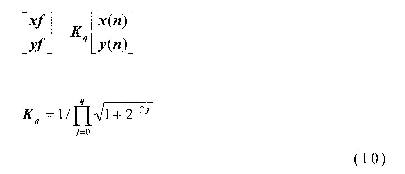
- the X and Y path constant multipliers 200x and 200y perform multiplication by a constant K q on x(n) and y(n), perform scaling processing as indicated by Expression (10), and output scaling results xf and yf of b bit width to the outside.
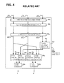
- Fig. 4 is a diagram showing a configuration of a linear approximation CORDIC circuit in second related technology. Details of the second related technology are also described in Non-Patent Document 1.
- the linear approximation CORDIC circuit 1002 of the second related technology is provided with: first to q-th rotation processing circuits 100 1 - 100 q , X and Y path constant multipliers 200x and 200y, X and Y path variable multipliers 300x and 300y, X and Y path adder/subtractors 400x and 400y, and a Z path constant multiplier 500.
- the Z path constant multiplier 500 is added, and the placements of the X and Y path constant multipliers 200x and 200y are moved to a stage before the X and Y path adder/subtractors 400x and 400y, respectively. Elements other than this are the same as those in Fig.3 .
- the linear approximation CORDIC circuit 1002 of the second related technology performs iterative processing by the rotation processing circuits 100 1 and 100 q , and obtains x(q), y(q), and z(q).
- the Z path constant multiplier 500 performs scaling processing on z(q), as indicated by Expression (11).
- x(q) and y(q) are multiplied by K q and P, and using the X and Y path adder/subtractors 400x and 400y, multiplied results are added or subtracted, and xf and yf are obtained and outputted to the outside.
- Non-Patent Document 1 Details of the Recoding processing are described in Non-Patent Document 1 and a description is omitted.
- processing of the X and Y path constant multipliers 200x and 200y, and the X and Y path variable multipliers 300x and 300y can be carried out in parallel, and since scaling processing in a later stage of the X and Y path adder/subtractors 400x and 400y is unnecessary, there is an advantage in that it is possible to shorten the processing delay, in comparison with the linear approximation CORDIC circuit 1001 of the first related technology.
- it is necessary to add the Z path constant multiplier 500 so that the circuit scale becomes large.
- the present invention is invented in light of the abovementioned problems, and it is an object of the invention to provide a CORDIC circuit and method that enable a reduction in circuit scale and realize shortening of the processing delay.
- the invention disclosed in the present application is configured generally as follows.
- a CORDIC circuit in which a scale correction process is divided into two steps, rough correction and fine correction, and the second process of a pseudo-rotation process is performed in parallel with the fine scale correction.
- a scale correction process is divided into two steps, rough correction and fine correction, and the second process of the pseudo-rotation process is performed in parallel with the fine scale correction.
- a scale correction process is divided into two stages including a rough correction stage and a fine correction stage, and a second half of a pseudo-rotation process is performed in parallel with the fine scale correction.
- the second half of the pseudo-rotation process may be realized by multiplication.
- the range of the fine scale correction may be set so that it is not necessary to perform scale correction with regard to a remaining rotation angle of the first half of the pseudo-rotation process.
- the scale correction process may be performed by iterative shift addition/subtraction
- the fine scale correction may be performed by an iterative shift addition/subtraction process in which a shift amount is half or more of required bit accuracy
- the rough scale correction may be performed by an iterative shift addition/subtraction process in which the shift amount is less than half of the required bit accuracy.
- the iterative shift addition/subtraction may be performed by a carry ripple adder/subtractor.
- a CORDIC operational circuit receiving a vector (X, Y) and a rotation angle (Z) as input includes an X path rough scale correction unit (610x) that performs rough scale correction on an X component (x[0]) of the vector, and outputs a result (K q1 * x[0]) of multiplication of a rough correction scaling coefficient (K q1 ) and the X component (x[0]), a Y path rough scale correction unit (610y) that performs rough scale correction on a Y component (y[0]) of the vector, and outputs a result (K q1 * y[0]) of multiplication of a rough correction scaling coefficient (K q1 ) and the Y component (y[0]), and a plurality of stages (q stages) of rotation processing circuits (100 1 to 100 q ) connected in a cascade arrangement.
- the rotation processing circuit (100 1 ) of a first stage receives the X component and the Y component outputted from the X and the Y path rough scale correction units and a rotation angle(Z) to perform iterative rotation process.
- the rotation processing circuits of later stages receive the X component and the Y component, and a rotation angle outputted from the rotation processing circuit of a preceding stage to perform an iterative rotation process.
- the CORDIC operational circuit further includes an X path fine scale correction unit (620x) that performs a fine scale correction process on the X component outputted from the rotation processing circuit (100 q ) of a last stage, and outputs a result of multiplying a fine correction scaling coefficient and the X component, a Y path fine scale correction unit (620y) that performs a fine scale correction process on the Y component outputted from the rotation processing circuit (100 q ) of the last stage, and outputs a result of multiplying a fine correction scaling coefficient and the Y component, an X path variable multiplier (300x) that is juxtaposed with the X path fine scale correction unit (620x) and multiplies the Y component y[q] outputted from the rotation processing circuit (100 q ) of the last stage by a rotation angle (z[q]) from the rotation processing circuit (100 q ) of the last stage, a Y path variable multiplier (300y) that is juxtaposed with the Y path fine scale correction unit (620
- the scale correction process may be performed by an iterative shift addition/subtraction process
- the rough scale correction may be performed by an iterative shift addition/subtraction process in which the shift amount is less than half the required bit accuracy
- the X path rough scale correction unit (610x) and the Y path rough scale correction unit (610y) include in plural stages a set of a barrel shifter that shifts input from a preceding stage, and a carry ripple adder/subtractor that receives as input to be added or subtracted, output of the barrel shifter and input from the preceding stage.
- the scale correction process may be performed by iterative shift addition/subtraction, and the fine scale correction may be performed by an iterative shift addition/subtraction process in which the shift amount is half or more of the required bit accuracy.
- the X path fine scale correction unit (620x) and the Y path fine scale correction unit (620y) may be configured to include a plurality of stages of sets of barrel shifters and carry ripple adder/subtractors.
- the barrel shifter shifts an input from a preceding stage.
- the carry ripple adder/subtractor receives as inputs an output of the barrel shifter and an input from the preceding stage to add or subtract the inputs.
- the plural stages of rotation processing circuits connected in cascade may be configured to be provided on an input stage side, and the X and the Y path rough scale correction units (610x and 610y) may be provided in a rear stage of the plural stages of the rotation processing circuits connected in cascade.
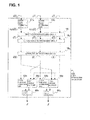
- Fig. 1 is a diagram showing a configuration of a linear approximation CORDIC circuit in one exemplary embodiment of the present invention.
- the linear approximation CORDIC circuit 1000 of the present exemplary embodiment includes: first to q-th rotation processing circuits 100 1 - 100 q , the X and the Y path rough scale correction units 610x and 610y, the X and the Y path fine scale correction units 620x and 620y, the X and Y path variable multipliers 300x and 300y, and X and Y path adder/subtractors 400x and 400y.
- the X and the Y path rough scale correction units 610x and 610y are divided into the X and the Y path rough scale correction units 610x and 610y, and the X and the Y path fine scale correction units 620x and 620y; the X and the Y path rough scale correction units 610x and 610y are each disposed at in input stage; and the X and the Y path fine scale correction units 620x and 620y are each disposed at a preceding stage of the X and Y path adder/subtractors 400x and 400y.
- a scaling coefficient K q indicated in Expression (10) can be approximated by an iterative shift addition process as indicated in Expression (13).
- Non-Patent Document 3 It is known that ⁇ which assumes a value other than 0, can be less than or equal to log2(n) (for details, reference should be made to the description of Non-Patent Document 3).
- an iterative shift addition process where scale correction is performed is divided into two stages, the fine scale correction unit where the shift amount is greater than or equal to n/2, and the rough correction process less than n/2.
- K q is given as the product of K q1 and K q2 as indicated in Expression (14).
- K q1 is derived (approximated) by an iterative shift addition process of the rough correction process of less than n/2.
- K q2 is derived (approximated) by an iterative shift addition process of the fine scale correction process in which the shift amount is greater than or equal to n/2.
- K q K q ⁇ 1 ⁇ K q ⁇ 2
- the linear approximation CORDIC circuit 1000 of the present exemplary embodiment has, as input, an input vector [x(0), y(0)]' and a desired rotation angle z(0), and the input vector [x(0), y(0)]' is supplied to the X and the Y path rough scale correction units 610x and 610y.
- the X and the Y path rough scale correction units 610x and 610y perform rough scale correction processing on the input vector [x(0), y(0)]' and supply K q1 x(0) and K q1 y(0) to a first rotation processing circuit 100 1 (K q1 is given as in Expression (15)).
- the first rotation processing circuit 100 1 has as input K q1 x(0), K q1 y(0), and z(0), performs processing as indicated in Expression (17), and supplies x(1), y(1), and z(1) to a second rotation processing circuit 100 2 .
- "sign" in Expression (17) is a sign operator.
- the second to q-th rotation processing circuits 100 2 to 100 q perform iterative processing as indicated by Expression (18) on x(1), y(1), and z(1), and output x(q), y(q), and z(q).
- b is given by Expression (8).
- an angle error E in case of z(q) not subjected to scaling processing is less than 2 -n and is smaller than an approximate value 2 -n+1 of K q2 ⁇ n-1 .
- x(q) and y(q) are multiplied by K q2 and z(q), in the X and Y path constant multipliers 200x and 200y (X and the Y path fine scale correction units 620x and 620y) and the X and Y path variable multipliers 300x and 300y, and using the X and Y path adder/subtractors 400x and 400y, the multiplication result is added or subtracted in accordance with Expression (23) to find xf and yf which are outputted to the outside.
- xf yf K q ⁇ 2 ⁇ x q + z q ⁇ y q K q ⁇ 2 ⁇ y q - z q ⁇ x q
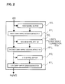
- Fig. 2 shows a configuration example of the X path rough scale correction unit 610x of the present exemplary embodiment. It is assumed that in the iterative shift addition/subtraction process indicated in Expression (13), ⁇ has a value other than 0, the number of shift addition/subtraction processes in which the shift amount is less than or equal to n/2 is k, and respective shift amounts are so, ... S k-1 .
- the X path rough scale correction unit 610x of the present exemplary embodiment is configured from first to k-th carry ripple adder/subtractors 611 1 to 611 k , and first to k-th barrel shifters 612 1 to 612 k .
- the first to k-th barrel shifters 612 1 to 612 k shift an input signal from a preceding stage, in accordance with the shift amounts of s 0 , ... s k-1 , respectively.
- the first to k-th carry ripple adder/subtractors 611 1 to 611 k add or subtract a shifted signal and an original signal in accordance with ⁇ s0 to ⁇ sk-1 .
- the Y path rough scale correction unit 610y and the X and Y path fine scale correction units 620x and 620y can be realized by a similar type of configuration.
- the carry ripple adder/subtractor confirms an addition/subtraction result from an LSB side and hence there is a problem that in iterative shift addition/subtraction processing, with a larger shift amount, calculation cannot be started until a preceding stage MSB side is confirmed.
- shift ripple delay A delay occurring due to this problem is referred to as "shift ripple delay".
- a shift ripple delay due to 1 bit shift is normalized as 1 shift ripple delay. If wiring delay is ignored, an LSB bit output delay of the scale correction unit matches a shift ripple delay of the total shift amount within the scale correction unit. Therefore, in a case the number of iteration stages is the same, in the rough scale correction units 610x and 610y and the fine scale correction units 620x and 620y, the delay of the fine scale correction units 620x and 620y is invariably large.
- the fine scale correction unit which covers a large portion of the delay due to the overall scale correction processing, carries out processing in parallel with the X and Y path constant multipliers 200x and 200y, compared to the linear approximation CORDIC circuit 1001 of the first related technology, it is possible to reduce the processing delay to a large extent.
- the scale correction is realized by iterative shift addition, and a division is made into 2 stages, the fine scale correction unit having a shift amount of n/2 or more, and the rough correction process of less than n/2, but if the range of the fine scale correction is set so that it is not necessary to do a scale correction with regard to a remaining rotation angle of the first half of the pseudo-rotation process, the present invention is clearly effective without depending on a method of implementing the scale correction.
- the present invention is not limited to the configuration in question, and is clearly effective without depending on a position of the rough scale correction.
- the X and the Y path rough scale correction units 610x and 610y may be disposed in a later stage of the first to q-th rotation process units 100 1 to 100 q .
- Non-Patent Documents 1, 2, and 3 are incorporated by reference into the present document. Modifications and adjustments of embodiments and examples are possible within bounds of the entire disclosure (including the range of the claims) of the present invention, and also based on fundamental technological concepts thereof. Furthermore, a wide variety of combinations and selections of various disclosed elements is possible within the scope of the claims of the present invention. That is, the present invention clearly includes every type of transformation and modification that a person skilled in the art can realize according to technological concepts and the entire disclosure including the scope of the claims.
Landscapes
- Engineering & Computer Science (AREA)
- General Physics & Mathematics (AREA)
- Theoretical Computer Science (AREA)
- Physics & Mathematics (AREA)
- Computing Systems (AREA)
- Mathematical Analysis (AREA)
- Mathematical Optimization (AREA)
- Pure & Applied Mathematics (AREA)
- General Engineering & Computer Science (AREA)
- Computational Mathematics (AREA)
- Image Processing (AREA)
- Transmission And Conversion Of Sensor Element Output (AREA)
- Complex Calculations (AREA)
Abstract
Description
- The present invention is based upon and claims the benefit of the priority of Japanese Patent Application No.
2008-056534 (filed on March 6, 2008 - The present invention relates to a Coordinate Rotation Digital Computer (referred to as CORDIC) operational circuit, and in particular, to a linear approximation CORDIC operational circuit and method.
- As a hardware-directed algorithm for an elementary function operation, such as a trigonometric function, a CORDIC (COordinate Rotation Digital Computer) algorithm is known. The CORDIC algorithm is an iterative solving method that takes a function as vector rotation on a two-dimensional plane, and finds a true value by iteratively computing vector rotation of a predetermined basic rotational angle.
- In the CORDIC algorithm, by selecting a rotational coordinate system (linear, circular, or hyperbolic), and by repeating a simple operation of a shift, addition, subtraction and table look-up, multiplication and division, trigonometric function computations, exponential and logarithmic computations, and hyperbolic function computations and the like can be executed, and the algorithm is widely used in digital signal processing fields.
- Taking circular polar coordinates as an example, a j-th rotation process is represented by Expression (1).
-

- Here, n is the number of iterations.
Furthermore,
σ j ∈ {1,-1} - is a rotation direction parameter.
- A vector [x(n), y(n)]' implementing a rotation of a rotational angle θ with respect to a vector [x(0), y(0)]' is represented by Expressions (2) and (3).
-

-

- Here, Kn is a scaling coefficient.
- Rotation according to the CORDIC algorithm is pseudo-rotation that accompanies scaling. In order to correct the scaling, it is necessary to perform processing indicated in Expression (4).
-

- As indicated in Expression (5), the CORDIC algorithm realizes a rotation operation of the rotational angle θ as a combination of basic rotation of angle αj.
-

- The CORDIC algorithm has 2 modes: a Rotation mode and a Vector mode, according to a method of determining the rotation direction parameter σj given in Expression (6).
-

- In the Rotation mode, with a desired angle θ as z(0), processing is performed to rotate, by an amount θ, an initial vector [x(0), y(0)]'.
- In the Vector mode, with an initial angle z(0) as 0, a process is performed to rotate the vector up to an x axis, and to obtain a rotational angle (z(n)) thereof and the norm (x(n)) of the initial vector.
- Since the CORDIC algorithm implements the rotation process by n basic rotations, essentially a rotational angle error less than a final basic rotational angle αn-1 occurs.
- In order that Expression (7) holds with n bit accuracy (refer to Non-Patent Document 1), the CORDIC algorithm must perform iterative processing of the same number of steps as the required bit accuracy.
-

- When the CORDIC algorithm is implemented, in addition to the rotational angle error, it is necessary to take into account a rounding error that accompanies the shift addition and subtraction.
- It is known that if bit width b of a data path satisfies Expression (8), an output value of n bit accuracy is obtained. Details thereof may be referred to in the descriptions of
Non-Patent Documents 1 and 2. -

- where, g is the number of MSB (Most Significant Bit) guard bits for an overflow strategy, and m is the number of LSB (Least Significant Bit) guard bits in a rounding error strategy.
- Since the CORDIC algorithm requires an iterative structure with the same number of stages as the required bit accuracy, it is difficult to realize speeding up using a parallel structure as seen in a multiplier.
- In order to solve this problem, a linear approximation CORDIC algorithm is proposed. The linear approximation CORDIC algorithm (Rotation mode), similar to the original algorithm, performs iterative processing as indicated by Expression (1) from j = 0 to n/2.
- Next, instead of iterative processing from j = n/2+1 to n-1, processing as indicated in Expression (9) is performed. Here, q = j/2. The process of the Expression (9) utilizes the fact that arctan(z(q))
can be linearly approximated by
z(q)
and this is the origin of the name of "linear approximation CORDIC". -

- Finally, scale correction as indicated by Expression (10) is performed.
-
- The linear approximation CORDIC shortens processing delay by performing multiplication in which speeding up is possible using a parallel structure, instead of shift addition/subtraction iterative processing in a later stage of the original CORDIC algorithm.
-
Fig. 3 is a diagram showing a typical structure of a linear approximation CORDIC circuit (Rotation mode) in first related technology. The first related technology as inFig. 3 , is referred to in the description of Non-PatentDocument 1. It is to be noted that in the present document, the description below concerns Rotation mode, as long as it is not particularly stated otherwise. - The linear
approximation CORDIC circuit 1001 includes: first to q-th rotation processing circuits 1001 - 100q, X and Y pathconstant multipliers path variable multipliers subtractors - The first to q-th rotation processing circuits 1001 - 100q perform iterative processing from j = 0 to q (= n/2), as indicated by Expression (1), with respect to initial values x(0), y(0), and z(0) to output x(q), y(q), and z(q).
- Here, n is required bit accuracy.
- Signals x(j), y(j), and z(j) are all of b bit width.
- Here, b is expressed by Expression (8).
- The X and Y
path variable multipliers subtractors - The X and Y
path variable multipliers
to extract only effective upper (n/2+m) bits of x(q), y(q), and z(q), and perform (n/2+m) x (n/2+m) bit variable multiplication. - The X and Y path
constant multipliers - Since Kq must be less than 1, the MSB guard bits g are unnecessary, and since the following expression may hold:
ct = b-g = n + m bits
the X and Y pathconstant multipliers - With regard to the linear
approximation CORDIC circuit 1001 of the first related technology, a method of further shortening the processing delay is proposed. -
Fig. 4 is a diagram showing a configuration of a linear approximation CORDIC circuit in second related technology. Details of the second related technology are also described in Non-PatentDocument 1. - The linear
approximation CORDIC circuit 1002 of the second related technology is provided with:
first to q-th rotation processing circuits 1001 - 100q,
X and Y pathconstant multipliers
X and Y pathvariable multipliers
X and Y path adder/subtractors
a Z pathconstant multiplier 500. - In the linear
approximation CORDIC circuit 1002 of the second related technology, in contrast to the linearapproximation CORDIC circuit 1001 of the first related technology, the Z pathconstant multiplier 500 is added, and the placements of the X and Y pathconstant multipliers subtractors Fig.3 . - The linear
approximation CORDIC circuit 1002 of the second related technology, similar to the first related technology, performs iterative processing by the rotation processing circuits 1001 and 100q, and obtains x(q), y(q), and z(q). - The Z path
constant multiplier 500 performs scaling processing on z(q), as indicated by Expression (11). -

- Next, processing as indicated in Expression (12) is performed.
-

- Specifically, in the X and Y path
constant multipliers variable multipliers subtractors - Since z(j) (j > n/3) can be obtained at high speed by Recoding processing utilizing the fact that Expression (7) holds, x(q) and y(q) form critical paths, even when the Z path
constant multiplier 500 is added. - Details of the Recoding processing are described in
Non-Patent Document 1 and a description is omitted. - In the linear
approximation CORDIC circuit 1002 of the second related technology, processing of the X and Y pathconstant multipliers variable multipliers subtractors approximation CORDIC circuit 1001 of the first related technology. However, it is necessary to add the Z pathconstant multiplier 500, so that the circuit scale becomes large. - Antelo, E. Villalba, J., "Low latency pipelined circular CORDIC" Computer Arithmetic 2005. ARITH-17 2005. Proceedings of 17th IEEE Symposium on Computer Arithmetic, pp. 280- 287 June 2005.
- YH Hu, "The quantization effects of the CORDIC algorithm" IEEE Transactions on Signal Processing 40:44, 834-844 pp. 1822-1825, 1988.
- E. F. Deprettere, P. Dewilde, and R. Udo, "Pipelined CORDIC architectures for fast VLSI filtering and array processing," in Proceedings IEEE ICASSP, pp. 41, March 1984.
- An analysis of related arts according to the present invention is given as follows.
- In a linear approximation CORDIC circuit in first related art technology, there is a problem in that, since a pseudo-rotation process and scale correction are carried out sequentially, processing delay becomes large.
- In a linear approximation CORDIC circuit in second related technology, there is a problem in that, a second half of the pseudo-rotation process and scale correction are preformed in parallel and a processing delay is shortened, so that scale correction is necessary with regard to remaining rotation angle of a first half of the pseudo-rotation process, and circuit scale becomes large.
- The present invention is invented in light of the abovementioned problems, and it is an object of the invention to provide a CORDIC circuit and method that enable a reduction in circuit scale and realize shortening of the processing delay.
- In order to solve the abovementioned problems, the invention disclosed in the present application is configured generally as follows.
- According to the present invention, there is provided a CORDIC circuit in which a scale correction process is divided into two steps, rough correction and fine correction, and the second process of a pseudo-rotation process is performed in parallel with the fine scale correction.
- According to the present invention, there is provided a method in which a scale correction process is divided into two steps, rough correction and fine correction, and the second process of the pseudo-rotation process is performed in parallel with the fine scale correction.
- According to the present invention, by performing the second process of the pseudo-rotation process and the fine scale correction step in parallel, it is possible to shorten processing delay.
- According to the present invention, since scale correction of a remaining rotation angle of the first process of the pseudo-rotation process is unnecessary, it is possible to reduce circuit scale.
-
-
Fig. 1 is a diagram showing a configuration of a first exemplary embodiment of the present invention. -
Fig. 2 is a diagram showing a configuration of an X path rough scale correction unit included in the first exemplary embodiment of the present invention. -
Fig. 3 is a diagram showing a configuration of a linear approximation CORDIC circuit in first related technology. -
Fig. 4 is a diagram showing a configuration of a linear approximation CORDIC circuit in second related technology. -
- 1001 to
- 100q first to q-th rotation processing circuits
- 200x
- X path constant multiplier
- 200y
- Y path constant multiplier
- 300x
- X path variable multiplier
- 300y
- Y path variable multiplier
- 400x
- X path adder/subtractor
- 400y
- Y path adder/subtractor
- 500
- Z path constant multiplier
- 610x
- X path rough scale correction unit
- 610y
- Y path rough scale correction unit
- 620x
- X path fine scale correction unit
- 620y
- Y path fine scale correction unit
- 6111 to 611k
- first to k-th carry ripple adder/subtractors
- 6121 to 612k
- first to k-th barrel shifters
- 1000
- linear approximation CORDIC circuit
- 1001
- linear approximation CORDIC circuit
- 1002
- linear approximation CORDIC circuit
- Exemplary embodiments of the present invention will be described below. In a linear approximation CORDIC circuit according to the present invention, a scale correction process is divided into two stages including a rough correction stage and a fine correction stage, and a second half of a pseudo-rotation process is performed in parallel with the fine scale correction.
- In one exemplary embodiment of the present invention, the second half of the pseudo-rotation process may be realized by multiplication.
- In one exemplary embodiment of the present invention, the range of the fine scale correction may be set so that it is not necessary to perform scale correction with regard to a remaining rotation angle of the first half of the pseudo-rotation process.
- In one exemplary embodiment of the present invention, the scale correction process may be performed by iterative shift addition/subtraction, the fine scale correction may be performed by an iterative shift addition/subtraction process in which a shift amount is half or more of required bit accuracy, and the rough scale correction may be performed by an iterative shift addition/subtraction process in which the shift amount is less than half of the required bit accuracy.
- In the present invention, the iterative shift addition/subtraction may be performed by a carry ripple adder/subtractor.
- In the present invention, a CORDIC operational circuit receiving a vector (X, Y) and a rotation angle (Z) as input includes
an X path rough scale correction unit (610x) that performs rough scale correction on an X component (x[0]) of the vector, and outputs a result (Kq1 * x[0]) of multiplication of a rough correction scaling coefficient (Kq1) and the X component (x[0]),
a Y path rough scale correction unit (610y) that performs rough scale correction on a Y component (y[0]) of the vector, and outputs a result (Kq1 * y[0]) of multiplication of a rough correction scaling coefficient (Kq1) and the Y component (y[0]), and
a plurality of stages (q stages) of rotation processing circuits (1001 to 100q) connected in a cascade arrangement.
The rotation processing circuit (1001) of a first stage receives the X component and the Y component outputted from the X and the Y path rough scale correction units and a rotation angle(Z) to perform iterative rotation process.
The rotation processing circuits of later stages receive the X component and the Y component, and a rotation angle outputted from the rotation processing circuit of a preceding stage to perform an iterative rotation process.
The CORDIC operational circuit further includes
an X path fine scale correction unit (620x) that performs a fine scale correction process on the X component outputted from the rotation processing circuit (100q) of a last stage, and outputs a result of multiplying a fine correction scaling coefficient and the X component,
a Y path fine scale correction unit (620y) that performs a fine scale correction process on the Y component outputted from the rotation processing circuit (100q) of the last stage, and outputs a result of multiplying a fine correction scaling coefficient and the Y component,
an X path variable multiplier (300x) that is juxtaposed with the X path fine scale correction unit (620x) and multiplies the Y component y[q] outputted from the rotation processing circuit (100q) of the last stage by a rotation angle (z[q]) from the rotation processing circuit (100q) of the last stage,
a Y path variable multiplier (300y) that is juxtaposed with the Y path fine scale correction unit (620y) and multiplies the X component x[q] outputted from the rotation processing circuit (100q) of the last stage by the rotation angle z[q] from the rotation processing circuit (100q) of the last stage,
an X path adder/subtractor (400x) that outputs a result (Kq2 * x[q] + z[q] * y[q]) of adding the multiplication result (Kq2 * x[q]) of the X path fine scale correction unit (620x) and the multiplication result (z[q] * y[q]) of the X path variable multiplier (300x); and
a Y path adder/subtractor (400y) that outputs a result (Kq2 * y[q] - z[q] * x[q]) of subtracting from the multiplication result (Kq2 * y[q]) of the Y path fine scale correction unit (620y), the multiplication result (z[q] * x[q]) of the Y path variable multiplier (300y). - In one exemplary embodiment of the present invention, in the X path rough scale correction unit (610x) and the Y path rough scale correction unit (610y), the scale correction process may be performed by an iterative shift addition/subtraction process, and the rough scale correction may be performed by an iterative shift addition/subtraction process in which the shift amount is less than half the required bit accuracy.
- In one exemplary embodiment of the present invention, the X path rough scale correction unit (610x) and the Y path rough scale correction unit (610y) include in plural stages a set of a barrel shifter that shifts input from a preceding stage, and a carry ripple adder/subtractor that receives as input to be added or subtracted, output of the barrel shifter and input from the preceding stage.
- In one exemplary embodiment of the present invention, in the X path fine scale correction unit (620x) and the Y path fine scale correction unit (620y), the scale correction process may be performed by iterative shift addition/subtraction, and the fine scale correction may be performed by an iterative shift addition/subtraction process in which the shift amount is half or more of the required bit accuracy.
- In one exemplary embodiment of the present invention, the X path fine scale correction unit (620x) and the Y path fine scale correction unit (620y) may be configured to include a plurality of stages of sets of barrel shifters and carry ripple adder/subtractors. The barrel shifter shifts an input from a preceding stage. The carry ripple adder/subtractor receives as inputs an output of the barrel shifter and an input from the preceding stage to add or subtract the inputs.
- In one exemplary embodiment of the present invention, the plural stages of rotation processing circuits connected in cascade may be configured to be provided on an input stage side, and the X and the Y path rough scale correction units (610x and 610y) may be provided in a rear stage of the plural stages of the rotation processing circuits connected in cascade.
-
Fig. 1 is a diagram showing a configuration of a linear approximation CORDIC circuit in one exemplary embodiment of the present invention. Referring toFig. 1 , the linearapproximation CORDIC circuit 1000 of the present exemplary embodiment includes: first to q-th rotation processing circuits 1001 - 100q,
the X and the Y path roughscale correction units
the X and the Y path finescale correction units
the X and Y pathvariable multipliers subtractors - If the linear
approximation CORDIC circuit 1000 of the present exemplary embodiment inFig. 1 is compared to the linearapproximation CORDIC circuit 1001 of the first related technology inFig. 3 , in the present exemplary embodiment, functions of the X and Y pathconstant multipliers Fig. 3 are divided into the X and the Y path roughscale correction units scale correction units scale correction units scale correction units subtractors - If the linear
approximation CORDIC circuit 1000 of the present exemplary embodiment inFig. 1 is compared with the linearapproximation CORDIC circuit 1002 of the second related technology inFig. 4 , in the present exemplary embodiment, functions of the X and Y pathconstant multipliers Fig. 4 are divided into the X and the Y path roughscale correction units scale correction units constant multiplier 500 is not necessary. - A description is given concerning operation and configuration of the present exemplary embodiment, with an exemplary case where the required bit accuracy is n.
- A scaling coefficient Kq indicated in Expression (10) can be approximated by an iterative shift addition process as indicated in Expression (13). In Expression (13), q is n/2. and
represents a product from j = 0 to j = n/2. -

- It is known that γ which assumes a value other than 0, can be less than or equal to log2(n) (for details, reference should be made to the description of Non-Patent Document 3).
- In the present exemplary embodiment, an iterative shift addition process where scale correction is performed is divided into two stages, the fine scale correction unit where the shift amount is greater than or equal to n/2, and the rough correction process less than n/2.
- In this way, by setting the range of the fine scale correction, it is not necessary to do a scale correction with regard to the remaining rotation angle of the first half of the pseudo-rotation process, that is, with regard to output z[q] of the rotation processing circuits 1001 to 100q.
- The scaling coefficient Kq is given as the product of Kq1 and Kq2 as indicated in Expression (14). As indicated in Expression (15), Kq1 is derived (approximated) by an iterative shift addition process of the rough correction process of less than n/2. As indicated in Expression (16), Kq2 is derived (approximated) by an iterative shift addition process of the fine scale correction process in which the shift amount is greater than or equal to n/2.
-

-

-

- The linear
approximation CORDIC circuit 1000 of the present exemplary embodiment has, as input, an input vector [x(0), y(0)]' and a desired rotation angle z(0), and the input vector [x(0), y(0)]' is supplied to the X and the Y path roughscale correction units - The X and the Y path rough
scale correction units - The first rotation processing circuit 1001 has as input Kq1x(0), Kq1y(0), and z(0), performs processing as indicated in Expression (17), and supplies x(1), y(1), and z(1) to a second rotation processing circuit 1002. It is to be noted that "sign" in Expression (17) is a sign operator.
-

- The second to q-th rotation processing circuits 1002 to 100q perform iterative processing as indicated by Expression (18) on x(1), y(1), and z(1), and output x(q), y(q), and z(q). Signals x(j), y(j), and z(j) (j = 0 to q) are all of b bit width. Here, b is given by Expression (8).
-

- In case of performing processing equivalent to the linear
approximation CORDIC circuit 1002 of the second related technology, the processing indicated in Expressions (19) and (20) may be performed regarding x(q), y(q), and z(q). -

-

- Here, in an original (not linear approximation) CORDIC, a rotation angle error less than a final basic rotation angle αn-1 (≈ 2-(n-1)) essentially occurs, but in consideration of the fact that n bit accuracy can be realized, it is understood that there is no problem if an error less than Kq2 αn-1 occurs in P indicated in Expression (19).
- In consideration of the fact that z(q) is less than 2-n/2, an angle error E in case of z(q) not subjected to scaling processing, is less than 2-n and is smaller than an approximate value 2-n+1 of Kq2 αn-1.
- Thus, in the linear approximation CORDIC circuit 100 of the present exemplary embodiment, it is possible to skip the scaling processing with regard to z(q).
-

-

- More specifically, x(q) and y(q) are multiplied by Kq2 and z(q), in the X and Y path
constant multipliers scale correction units variable multipliers subtractors -

-
Fig. 2 shows a configuration example of the X path roughscale correction unit 610x of the present exemplary embodiment. It is assumed that in the iterative shift addition/subtraction process indicated in Expression (13), γ has a value other than 0, the number of shift addition/subtraction processes in which the shift amount is less than or equal to n/2 is k, and respective shift amounts are so, ... Sk-1. - In this case, the X path rough
scale correction unit 610x of the present exemplary embodiment is configured from first to k-th carry ripple adder/subtractors 6111 to 611k, and first to k-th barrel shifters 6121 to 612k. The first to k-th barrel shifters 6121 to 612k shift an input signal from a preceding stage, in accordance with the shift amounts of s0, ... sk-1, respectively. - The first to k-th carry ripple adder/
subtractors 6111 to 611k add or subtract a shifted signal and an original signal in accordance with γs0 to γsk-1. - In case of n = 16, Kq is expressed by {1 + 2^(-2)} * {1 - 2^(-5)} * {1 + 2^(-9)} * {1 + 2^(-10)} (note that ^ indicates an exponent), and k = 2, s0 = 2, s1 = 5.
- The Y path rough
scale correction unit 610y and the X and Y path finescale correction units - The carry ripple adder/subtractor confirms an addition/subtraction result from an LSB side and hence there is a problem that in iterative shift addition/subtraction processing, with a larger shift amount, calculation cannot be started until a preceding stage MSB side is confirmed.
- A delay occurring due to this problem is referred to as "shift ripple delay". A shift ripple delay due to 1 bit shift is normalized as 1 shift ripple delay. If wiring delay is ignored, an LSB bit output delay of the scale correction unit matches a shift ripple delay of the total shift amount within the scale correction unit. Therefore, in a case the number of iteration stages is the same, in the rough
scale correction units scale correction units scale correction units - In case of n = 16, the delay ratio is (9 + 10)/(2 + 5) = 2.7 times. In the entire shift ripple delays, the ratio occupied by the rough scale correction unit is (2 + 5)/(2 + 5 + 9 + 10) = 27%.
- It is to be noted that in the configuration of the present embodiment fa description has been given with the carry ripple adder/subtractors as an example, but the present invention clearly does not depend on adder/subtractor method.
- In the present exemplary embodiment, since the ratio occupied by the rough scale correction unit is very low with respect to the scale correction process overall delay, compared with the linear
approximation CORDIC circuit 1002 of the second related technology, almost no process delay increase occurs. At the same time, since a scaling process with regard to the Z path is unnecessary, the circuit scale can be reduced. - In the present exemplary embodiment, since the fine scale correction unit, which covers a large portion of the delay due to the overall scale correction processing, carries out processing in parallel with the X and Y path
constant multipliers approximation CORDIC circuit 1001 of the first related technology, it is possible to reduce the processing delay to a large extent. - It is to be noted that in the present exemplary embodiment a description has been given of an example of a case where the scale correction is realized by iterative shift addition, and a division is made into 2 stages, the fine scale correction unit having a shift amount of n/2 or more, and the rough correction process of less than n/2, but if the range of the fine scale correction is set so that it is not necessary to do a scale correction with regard to a remaining rotation angle of the first half of the pseudo-rotation process, the present invention is clearly effective without depending on a method of implementing the scale correction.
- Furthermore, a description has been given of the present exemplary embodiment with an exemplary case where the rough scale correction is performed at the input stage, but the present invention is not limited to the configuration in question, and is clearly effective without depending on a position of the rough scale correction. For example, the X and the Y path rough
scale correction units - Each disclosure of the abovementioned
Non-Patent Documents 1, 2, and 3 is incorporated by reference into the present document. Modifications and adjustments of embodiments and examples are possible within bounds of the entire disclosure (including the range of the claims) of the present invention, and also based on fundamental technological concepts thereof. Furthermore, a wide variety of combinations and selections of various disclosed elements is possible within the scope of the claims of the present invention. That is, the present invention clearly includes every type of transformation and modification that a person skilled in the art can realize according to technological concepts and the entire disclosure including the scope of the claims.
Claims (18)
- A CORDIC computation circuit comprising:a scale correction process divided into two stages including a rough scale correction stage and a fine scale correction stage; anda pseudo-rotation process with a second half thereof performed in parallel with the fine scale correction stage.
- The CORDIC computation circuit according to claim 1, wherein the second half of the pseudo-rotation process is realized by multiplication.
- The CORDIC computation circuit according to claim 1 or 2, wherein the fine scale correction has a range set so as to make it unnecessary to perform a scale correction with regard to a remaining rotation angle of a first half of the pseudo-rotation process.
- The CORDIC computation circuit according to any one of claims 1 to 3, wherein the scale correction process is performed by iterative shift addition/subtraction,
the fine scale correction is performed by an iterative shift addition/subtraction process in which a shift amount is half or more of a required bit accuracy, and
the rough scale correction is performed by an iterative shift addition/subtraction process in which the shift amount is less than half of a required bit accuracy. - The CORDIC computation circuit according to claim 4, wherein the iterative shift addition/subtraction is performed using a carry ripple adder/subtractor.
- A CORDIC computation circuit receiving a vector (X, Y) and a rotation angle (Z) as inputs, comprising:an X path rough scale correction unit that performs rough scale correction on an X component of the vector (X, Y), and outputs a result of multiplication of a rough correction scaling coefficient and the X component;a Y path rough scale correction unit that performs rough scale correction on a Y component of the vector, and outputs a result of multiplication of a rough correction scaling coefficient and the Y component;a plurality of stages of rotation processing circuits connected in cascade,the rotation processing circuit of a first stage receiving an X component and a Y component outputted respectively from the X and Y path rough scale correction units, and a rotation angle to perform an iterative rotation process, a rotation processing circuit of a later stage receiving an X component, a Y component and a rotation angle outputted from a rotation processing circuit of a preceding stage to perform an iterative rotation process;an X path fine scale correction unit that performs a fine scale correction on an X component outputted from the rotation processing circuit of a last stage, and outputs a result of multiplying a fine correction scaling coefficient and the X component;a Y path fine scale correction unit that performs a fine scale correction on a Y component outputted from the rotation processing circuit of a last stage, and outputs a result of multiplication of a fine correction scaling coefficient and the Y component;an X path variable multiplier juxtaposed with the X path fine scale correction unit to multiply a Y component outputted from the rotation processing circuit of a last stage by a rotation angle from the rotation processing circuit of a last stage;a Y path variable multiplier juxtaposed with the Y path fine scale correction unit to multiply an X component outputted from the rotation processing circuit of a last stage by a rotation angle from the rotation processing circuit of a last stage;an X path adder/subtractor that outputs a result of adding or subtracting a multiplication result of the X path fine scale correction unit and a multiplication result of the X path variable multiplier; anda Y path adder/subtractor that outputs a result of adding or subtracting a multiplication result of the Y path fine scale correction unit and a multiplication result of the Y path variable multiplier.
- The CORDIC computation circuit according to claim 6, wherein, in the X path rough scale correction unit and the Y path rough scale correction unit, the scale correction process is performed by iterative shift addition/subtraction, and rough scale correction is performed by an iterative shift addition/subtraction process in which the shift amount is less than half a required bit accuracy.
- The CORDIC computation circuit according to claim 7, wherein the X and Y path rough scale correction units include plural stages of sets, each set including
a barrel shifter that shifts an input from a preceding stage; and
a carry ripple adder/subtractor that receives an input from a preceding stage and an output of the barrel shifter to perform addition or subtraction of the received signals. - The CORDIC computation circuit according to claim 6 or 7, wherein, in the X and Y path fine scale correction units, the scale correction process is performed by iterative shift addition/subtraction, and the fine scale correction is performed by an iterative shift addition/subtraction process in which a shift amount is half or more of a required bit accuracy.
- The CORDIC computation circuit according to claim 9, wherein the X and Y path fine scale correction units include plural stages of sets, each set including:a barrel shifter that shifts an input from a preceding stage; anda carry ripple adder/subtractor that receives an input from a preceding stage and an output of the barrel shifter to perform addition or subtraction of the received signals.
- The CORDIC computation circuit according to claim 6, wherein the plurality of stages of the rotation processing circuits connected in cascade are provided on an input stage side, and the X and Y path rough scale correction units are provided at a rear stage of the plurality of stages of the rotation processing circuits connected in cascade.
- A CORDIC operational method, comprising:dividing a scale correction process into two steps including a rough scale correction step and a fine scale correction step; andexecuting a second half of a pseudo-rotation process in parallel with the fine scale correction step.
- The CORDIC operational method according to claim 12, wherein a second half of the pseudo-rotation process is realized by multiplication.
- The CORDIC operational method according to claim 12 or 13, wherein the range of the fine scale correction is set so as to make it unnecessary to perform a scale correction with regard to a remaining rotation angle of a first half of the pseudo-rotation process.
- The CORDIC operational method according to any one of claims 12 to 14, wherein the scale correction process is performed by iterative shift addition/subtraction,
the fine scale correction is performed by an iterative shift addition/subtraction process in which a shift amount is half or more than a required bit accuracy, and
the rough scale correction is performed by an iterative shift addition/subtraction process in which the shift amount is less than half of a required bit accuracy. - The CORDIC operational method according to claim 15, wherein the iterative shift addition/subtraction is performed by a carry ripple adder/subtractor.
- A CORDIC computation circuit receiving a vector (X, Y) and a rotation angle (Z), comprising:an X path rough scale correction unit that performs a rough scale correction process on an X component x(0) of an input vector, and outputs Kq1 * x(0);a Y path rough scale correction unit that performs a rough scale correction process on a Y component y(0) of the input vector, and outputs Kq1 * y(0);first to q-th rotation processing circuits connected in cascade;an X path fine scale correction unit that performs a fine scale correction process on an X component x(q) outputted from the q-th rotation processing circuit, and outputs a result Kq2 * x(q) of multiplying a fine correction scaling coefficient Kq2 and the X component x(q);a Y path fine scale correction unit that performs a fine scale correction process on a Y component y(q) outputted from the q-th rotation processing circuit, and outputs a result Kq2 * y(q) of multiplying a fine correction scaling coefficient Kq2 and the Y component y(q);an X path variable multiplier juxtasposed with the X path fine scale correction unit to output a result z(q) * y(q) of multiplying a Y component y(q) outputted from the q-th rotation processing circuit and a rotation angle z(q) from the q-th rotation processing circuit;a Y path variable multiplier juxtasposed with the Y path fine scale correction unit to output a result z(q) * x(q) of multiplying an X component x(q) outputted from the q-th rotation processing circuit and a rotation angle z(q) from the q-th rotation processing circuit;an X path adder/subtractor that outputs a result of adding a multiplication result Kq2 * x(q) of the X path fine scale correction unit and a multiplication result z(q) * y(q) of the X path variable multiplier; anda Y path adder/subtractor that outputs a result of subtracting a multiplication result Kq2 * y(q) of the Y path fine scale correction unit and a multiplication result z(q) * x(q) of the Y path variable multiplier; whereina scaling coefficient Kq is expressed as a product Kq1 * Kq2 of the rough correction scaling coefficient Kq1 and the fine correction scaling coefficient Kq2,the rough correction scaling coefficient Kq1, being given as:

where in the X path rough scale correction unit and Y path rough scale correction unit, a rough scale correction being derived by an iterative shift addition process, for scale correction, of less than half of a prescribed bit accuracy n ,the fine correction scaling coefficient Kq2 being given as
γ j = {-1,0,1}the first rotation processing circuit receiving Kq1 * x(0) and Kq1
* y(0) outputted from the X path rough scale correction unit and the Y path rough scale correction unit, and a rotation angle z(0) to output vector x(1) and y(1) and rotation angle z(1) by computation as follows:


 a (j+1)-th rotation processing circuit (where j = 1 to q-1) receiving x(j), y(j), and z(j) outputted from a j-th rotation processing circuit to output vector x(j + 1) and y(j + 1) and rotation angle z(j + 1) by computation as follows:


computation of a product Kq2 * x(q) of the fine correction scaling coefficient Kq2 and output x(q) of the q-th rotation processing circuit, in the X path fine scale correction unit, and computation of a product z(q) * y(q) of output z(q) and y(q) of the q-th rotation processing circuit, in the X path variable multiplier, being performed in parallel,
computation of a product Kq2 * y(q) of the fine correction scaling coefficient Kq2 and output y(q) of the q-th rotation processing circuit, in the Y path fine scale correction unit, and computation of a product z(q) * x(q) of output z(q) and x(q) of the q-th rotation processing circuit, in the Y path variable multiplier, being performed in parallel,
the X path adder/subtractor outputting Kq2 * x(q) + z(q) * y(q),
and
the Y path adder/subtractor outputting Kq2 * y(q) - z(q) * x(q). - The CORDIC computation circuit according to claim 17, wherein a scaling process on an output z(q) of the q-th rotation processing circuit is skipped.
Applications Claiming Priority (2)
| Application Number | Priority Date | Filing Date | Title |
|---|---|---|---|
| JP2008056534 | 2008-03-06 | ||
| PCT/JP2009/054188 WO2009110560A1 (en) | 2008-03-06 | 2009-03-05 | Cordic operational circuit and method |
Publications (3)
| Publication Number | Publication Date |
|---|---|
| EP2254041A1 true EP2254041A1 (en) | 2010-11-24 |
| EP2254041A4 EP2254041A4 (en) | 2011-05-11 |
| EP2254041B1 EP2254041B1 (en) | 2014-11-26 |
Family
ID=41056112
Family Applications (1)
| Application Number | Title | Priority Date | Filing Date |
|---|---|---|---|
| EP09717736.4A Not-in-force EP2254041B1 (en) | 2008-03-06 | 2009-03-05 | Cordic operational circuit and method |
Country Status (4)
| Country | Link |
|---|---|
| US (1) | US8572152B2 (en) |
| EP (1) | EP2254041B1 (en) |
| JP (1) | JP5229314B2 (en) |
| WO (1) | WO2009110560A1 (en) |
Families Citing this family (6)
| Publication number | Priority date | Publication date | Assignee | Title |
|---|---|---|---|---|
| US8572151B2 (en) * | 2010-03-15 | 2013-10-29 | Integrated Device Technology, Inc. | Methods and apparatuses for cordic processing |
| US9021003B2 (en) | 2010-06-23 | 2015-04-28 | Nec Corporation | Processor and operating method |
| RU2473961C1 (en) * | 2011-12-12 | 2013-01-27 | Виктор Николаевич Бабенко | Vector normalising apparatus |
| JP6335661B2 (en) * | 2014-06-04 | 2018-05-30 | キヤノン株式会社 | Arithmetic apparatus and control method thereof |
| US10168992B1 (en) * | 2017-08-08 | 2019-01-01 | Texas Instruments Incorporated | Interruptible trigonometric operations |
| CN109032564B (en) * | 2018-08-16 | 2022-12-02 | 电子科技大学 | A High Stability CORDIC Algorithm Implementation Circuit |
Family Cites Families (8)
| Publication number | Priority date | Publication date | Assignee | Title |
|---|---|---|---|---|
| EP1065853B1 (en) | 1999-06-29 | 2009-02-11 | Sony Deutschland GmbH | Broadcast receiver for multi-transmission system |
| EP0632369A1 (en) * | 1993-06-29 | 1995-01-04 | Stichting voor de Technische Wetenschappen | CORDIC algorithms and architectures |
| JP3095348B2 (en) | 1996-02-16 | 2000-10-03 | 松下電器産業株式会社 | Discrete cosine transform and inverse discrete cosine transform device in data compression / decompression device |
| JP2000131419A (en) | 1998-10-21 | 2000-05-12 | Mitsubishi Electric Corp | Arithmetic unit |
| US6480871B1 (en) * | 1999-04-07 | 2002-11-12 | Dhananjay S. Phatak | Algorithm (Method) and VLSI architecture for fast evaluation of trigonometric functions |
| US6772181B1 (en) * | 1999-10-29 | 2004-08-03 | Pentomics, Inc. | Apparatus and method for trigonometric interpolation |
| JP2007520009A (en) * | 2004-01-28 | 2007-07-19 | コーニンクレッカ フィリップス エレクトロニクス エヌ ヴィ | Implementation of the CORDIC algorithm for complex phase rotation |
| US20060200510A1 (en) * | 2005-01-31 | 2006-09-07 | Wang Cindy C | Precision cordic processor |
-
2009
- 2009-03-05 WO PCT/JP2009/054188 patent/WO2009110560A1/en not_active Ceased
- 2009-03-05 US US12/919,632 patent/US8572152B2/en active Active
- 2009-03-05 JP JP2010501957A patent/JP5229314B2/en active Active
- 2009-03-05 EP EP09717736.4A patent/EP2254041B1/en not_active Not-in-force
Also Published As
| Publication number | Publication date |
|---|---|
| WO2009110560A1 (en) | 2009-09-11 |
| US8572152B2 (en) | 2013-10-29 |
| US20110010408A1 (en) | 2011-01-13 |
| JP5229314B2 (en) | 2013-07-03 |
| JPWO2009110560A1 (en) | 2011-07-14 |
| EP2254041B1 (en) | 2014-11-26 |
| EP2254041A4 (en) | 2011-05-11 |
Similar Documents
| Publication | Publication Date | Title |
|---|---|---|
| CN104246690B (en) | System and method for signal processing in a digital signal processor | |
| Vahdat et al. | TruncApp: A truncation-based approximate divider for energy efficient DSP applications | |
| US9256397B2 (en) | Fused multiply-adder with booth-encoding | |
| EP2254041A1 (en) | Cordic operational circuit and method | |
| KR100241076B1 (en) | Floating- point multiply-and-accumulate unit with classes for alignment and normalization | |
| US5060182A (en) | Method and apparatus for performing the square root function using a rectangular aspect ratio multiplier | |
| US20230333812A1 (en) | Method and system for processing floating point numbers | |
| Hormigo et al. | Measuring improvement when using HUB formats to implement floating-point systems under round-to-nearest | |
| US9851947B2 (en) | Arithmetic processing method and arithmetic processor having improved fixed-point error | |
| US8990278B1 (en) | Circuitry for computing mathematical functions | |
| US10303439B2 (en) | Logarithm and power (exponentiation) computations using modern computer architectures | |
| US12175209B2 (en) | Process for performing floating point multiply-accumulate operations with precision based on exponent differences for saving power | |
| CN105573712B (en) | Apparatus, method and storage medium for calculating results of iterative sums | |
| US11010135B2 (en) | Arithmetic processing device and control method of arithmetic processing device | |
| Lewis | Complex logarithmic number system arithmetic using high-radix redundant CORDIC algorithms | |
| US9612800B2 (en) | Implementing a square root operation in a computer system | |
| CN112783470A (en) | Device and method for executing floating point logarithm operation | |
| US20230086090A1 (en) | Methods and Apparatus for Quotient Digit Recoding in a High-Performance Arithmetic Unit | |
| Das et al. | Implementation of four common functions on an LNS co-processor | |
| US12079593B2 (en) | Power saving floating point Multiplier-Accumulator with a high precision accumulation detection mode | |
| US7599980B1 (en) | Efficient hardware square-root operation | |
| Prasanna et al. | An efficient fused floating-point dot product unit using vedic mathematics | |
| Lakshmi et al. | Low latency VLSI architecture for the radix-4 CORDIC algorithm | |
| Lakshmi et al. | FPGA implementation of a high speed VLSI architecture for CORDIC | |
| US12106069B2 (en) | Power saving floating point multiplier-accumulator with precision-aware accumulation |
Legal Events
| Date | Code | Title | Description |
|---|---|---|---|
| PUAI | Public reference made under article 153(3) epc to a published international application that has entered the european phase |
Free format text: ORIGINAL CODE: 0009012 |
|
| 17P | Request for examination filed |
Effective date: 20101006 |
|
| AK | Designated contracting states |
Kind code of ref document: A1 Designated state(s): AT BE BG CH CY CZ DE DK EE ES FI FR GB GR HR HU IE IS IT LI LT LU LV MC MK MT NL NO PL PT RO SE SI SK TR |
|
| AX | Request for extension of the european patent |
Extension state: AL BA RS |
|
| A4 | Supplementary search report drawn up and despatched |
Effective date: 20110413 |
|
| DAX | Request for extension of the european patent (deleted) | ||
| RIC1 | Information provided on ipc code assigned before grant |
Ipc: G06T 1/20 20060101ALI20110826BHEP Ipc: G06F 7/548 20060101AFI20110826BHEP Ipc: G06T 3/60 20060101ALI20110826BHEP |
|
| 17Q | First examination report despatched |
Effective date: 20120622 |
|
| GRAP | Despatch of communication of intention to grant a patent |
Free format text: ORIGINAL CODE: EPIDOSNIGR1 |
|
| INTG | Intention to grant announced |
Effective date: 20140623 |
|
| GRAS | Grant fee paid |
Free format text: ORIGINAL CODE: EPIDOSNIGR3 |
|
| GRAA | (expected) grant |
Free format text: ORIGINAL CODE: 0009210 |
|
| AK | Designated contracting states |
Kind code of ref document: B1 Designated state(s): AT BE BG CH CY CZ DE DK EE ES FI FR GB GR HR HU IE IS IT LI LT LU LV MC MK MT NL NO PL PT RO SE SI SK TR |
|
| REG | Reference to a national code |
Ref country code: GB Ref legal event code: FG4D |
|
| REG | Reference to a national code |
Ref country code: CH Ref legal event code: EP |
|
| REG | Reference to a national code |
Ref country code: AT Ref legal event code: REF Ref document number: 698549 Country of ref document: AT Kind code of ref document: T Effective date: 20141215 |
|
| REG | Reference to a national code |
Ref country code: IE Ref legal event code: FG4D |
|
| REG | Reference to a national code |
Ref country code: DE Ref legal event code: R096 Ref document number: 602009027952 Country of ref document: DE Effective date: 20150108 |
|
| REG | Reference to a national code |
Ref country code: NL Ref legal event code: VDEP Effective date: 20141126 |
|
| REG | Reference to a national code |
Ref country code: AT Ref legal event code: MK05 Ref document number: 698549 Country of ref document: AT Kind code of ref document: T Effective date: 20141126 |
|
| REG | Reference to a national code |
Ref country code: LT Ref legal event code: MG4D |
|
| PG25 | Lapsed in a contracting state [announced via postgrant information from national office to epo] |
Ref country code: ES Free format text: LAPSE BECAUSE OF FAILURE TO SUBMIT A TRANSLATION OF THE DESCRIPTION OR TO PAY THE FEE WITHIN THE PRESCRIBED TIME-LIMIT Effective date: 20141126 Ref country code: NO Free format text: LAPSE BECAUSE OF FAILURE TO SUBMIT A TRANSLATION OF THE DESCRIPTION OR TO PAY THE FEE WITHIN THE PRESCRIBED TIME-LIMIT Effective date: 20150226 Ref country code: PT Free format text: LAPSE BECAUSE OF FAILURE TO SUBMIT A TRANSLATION OF THE DESCRIPTION OR TO PAY THE FEE WITHIN THE PRESCRIBED TIME-LIMIT Effective date: 20150326 Ref country code: NL Free format text: LAPSE BECAUSE OF FAILURE TO SUBMIT A TRANSLATION OF THE DESCRIPTION OR TO PAY THE FEE WITHIN THE PRESCRIBED TIME-LIMIT Effective date: 20141126 Ref country code: FI Free format text: LAPSE BECAUSE OF FAILURE TO SUBMIT A TRANSLATION OF THE DESCRIPTION OR TO PAY THE FEE WITHIN THE PRESCRIBED TIME-LIMIT Effective date: 20141126 Ref country code: IS Free format text: LAPSE BECAUSE OF FAILURE TO SUBMIT A TRANSLATION OF THE DESCRIPTION OR TO PAY THE FEE WITHIN THE PRESCRIBED TIME-LIMIT Effective date: 20150326 Ref country code: LT Free format text: LAPSE BECAUSE OF FAILURE TO SUBMIT A TRANSLATION OF THE DESCRIPTION OR TO PAY THE FEE WITHIN THE PRESCRIBED TIME-LIMIT Effective date: 20141126 |
|
| PG25 | Lapsed in a contracting state [announced via postgrant information from national office to epo] |
Ref country code: AT Free format text: LAPSE BECAUSE OF FAILURE TO SUBMIT A TRANSLATION OF THE DESCRIPTION OR TO PAY THE FEE WITHIN THE PRESCRIBED TIME-LIMIT Effective date: 20141126 Ref country code: CY Free format text: LAPSE BECAUSE OF FAILURE TO SUBMIT A TRANSLATION OF THE DESCRIPTION OR TO PAY THE FEE WITHIN THE PRESCRIBED TIME-LIMIT Effective date: 20141126 Ref country code: SE Free format text: LAPSE BECAUSE OF FAILURE TO SUBMIT A TRANSLATION OF THE DESCRIPTION OR TO PAY THE FEE WITHIN THE PRESCRIBED TIME-LIMIT Effective date: 20141126 Ref country code: HR Free format text: LAPSE BECAUSE OF FAILURE TO SUBMIT A TRANSLATION OF THE DESCRIPTION OR TO PAY THE FEE WITHIN THE PRESCRIBED TIME-LIMIT Effective date: 20141126 Ref country code: GR Free format text: LAPSE BECAUSE OF FAILURE TO SUBMIT A TRANSLATION OF THE DESCRIPTION OR TO PAY THE FEE WITHIN THE PRESCRIBED TIME-LIMIT Effective date: 20150227 Ref country code: LV Free format text: LAPSE BECAUSE OF FAILURE TO SUBMIT A TRANSLATION OF THE DESCRIPTION OR TO PAY THE FEE WITHIN THE PRESCRIBED TIME-LIMIT Effective date: 20141126 |
|
| PG25 | Lapsed in a contracting state [announced via postgrant information from national office to epo] |
Ref country code: DK Free format text: LAPSE BECAUSE OF FAILURE TO SUBMIT A TRANSLATION OF THE DESCRIPTION OR TO PAY THE FEE WITHIN THE PRESCRIBED TIME-LIMIT Effective date: 20141126 Ref country code: EE Free format text: LAPSE BECAUSE OF FAILURE TO SUBMIT A TRANSLATION OF THE DESCRIPTION OR TO PAY THE FEE WITHIN THE PRESCRIBED TIME-LIMIT Effective date: 20141126 Ref country code: SK Free format text: LAPSE BECAUSE OF FAILURE TO SUBMIT A TRANSLATION OF THE DESCRIPTION OR TO PAY THE FEE WITHIN THE PRESCRIBED TIME-LIMIT Effective date: 20141126 Ref country code: CZ Free format text: LAPSE BECAUSE OF FAILURE TO SUBMIT A TRANSLATION OF THE DESCRIPTION OR TO PAY THE FEE WITHIN THE PRESCRIBED TIME-LIMIT Effective date: 20141126 Ref country code: RO Free format text: LAPSE BECAUSE OF FAILURE TO SUBMIT A TRANSLATION OF THE DESCRIPTION OR TO PAY THE FEE WITHIN THE PRESCRIBED TIME-LIMIT Effective date: 20141126 |
|
| REG | Reference to a national code |
Ref country code: DE Ref legal event code: R097 Ref document number: 602009027952 Country of ref document: DE |
|
| PG25 | Lapsed in a contracting state [announced via postgrant information from national office to epo] |
Ref country code: PL Free format text: LAPSE BECAUSE OF FAILURE TO SUBMIT A TRANSLATION OF THE DESCRIPTION OR TO PAY THE FEE WITHIN THE PRESCRIBED TIME-LIMIT Effective date: 20141126 |
|
| PLBE | No opposition filed within time limit |
Free format text: ORIGINAL CODE: 0009261 |
|
| STAA | Information on the status of an ep patent application or granted ep patent |
Free format text: STATUS: NO OPPOSITION FILED WITHIN TIME LIMIT |
|
| PG25 | Lapsed in a contracting state [announced via postgrant information from national office to epo] |
Ref country code: LU Free format text: LAPSE BECAUSE OF FAILURE TO SUBMIT A TRANSLATION OF THE DESCRIPTION OR TO PAY THE FEE WITHIN THE PRESCRIBED TIME-LIMIT Effective date: 20150305 Ref country code: MC Free format text: LAPSE BECAUSE OF FAILURE TO SUBMIT A TRANSLATION OF THE DESCRIPTION OR TO PAY THE FEE WITHIN THE PRESCRIBED TIME-LIMIT Effective date: 20141126 |
|
| REG | Reference to a national code |
Ref country code: CH Ref legal event code: PL |
|
| 26N | No opposition filed |
Effective date: 20150827 |
|
| PG25 | Lapsed in a contracting state [announced via postgrant information from national office to epo] |
Ref country code: IT Free format text: LAPSE BECAUSE OF FAILURE TO SUBMIT A TRANSLATION OF THE DESCRIPTION OR TO PAY THE FEE WITHIN THE PRESCRIBED TIME-LIMIT Effective date: 20141126 |
|
| REG | Reference to a national code |
Ref country code: IE Ref legal event code: MM4A |
|
| PG25 | Lapsed in a contracting state [announced via postgrant information from national office to epo] |
Ref country code: LI Free format text: LAPSE BECAUSE OF NON-PAYMENT OF DUE FEES Effective date: 20150331 Ref country code: CH Free format text: LAPSE BECAUSE OF NON-PAYMENT OF DUE FEES Effective date: 20150331 Ref country code: IE Free format text: LAPSE BECAUSE OF NON-PAYMENT OF DUE FEES Effective date: 20150305 |
|
| REG | Reference to a national code |
Ref country code: FR Ref legal event code: PLFP Year of fee payment: 8 |
|
| PG25 | Lapsed in a contracting state [announced via postgrant information from national office to epo] |
Ref country code: SI Free format text: LAPSE BECAUSE OF FAILURE TO SUBMIT A TRANSLATION OF THE DESCRIPTION OR TO PAY THE FEE WITHIN THE PRESCRIBED TIME-LIMIT Effective date: 20141126 |
|
| PG25 | Lapsed in a contracting state [announced via postgrant information from national office to epo] |
Ref country code: MT Free format text: LAPSE BECAUSE OF FAILURE TO SUBMIT A TRANSLATION OF THE DESCRIPTION OR TO PAY THE FEE WITHIN THE PRESCRIBED TIME-LIMIT Effective date: 20141126 |
|
| REG | Reference to a national code |
Ref country code: FR Ref legal event code: PLFP Year of fee payment: 9 |
|
| PG25 | Lapsed in a contracting state [announced via postgrant information from national office to epo] |
Ref country code: BG Free format text: LAPSE BECAUSE OF FAILURE TO SUBMIT A TRANSLATION OF THE DESCRIPTION OR TO PAY THE FEE WITHIN THE PRESCRIBED TIME-LIMIT Effective date: 20141126 Ref country code: HU Free format text: LAPSE BECAUSE OF FAILURE TO SUBMIT A TRANSLATION OF THE DESCRIPTION OR TO PAY THE FEE WITHIN THE PRESCRIBED TIME-LIMIT; INVALID AB INITIO Effective date: 20090305 |
|
| PG25 | Lapsed in a contracting state [announced via postgrant information from national office to epo] |
Ref country code: TR Free format text: LAPSE BECAUSE OF FAILURE TO SUBMIT A TRANSLATION OF THE DESCRIPTION OR TO PAY THE FEE WITHIN THE PRESCRIBED TIME-LIMIT Effective date: 20141126 |
|
| PG25 | Lapsed in a contracting state [announced via postgrant information from national office to epo] |
Ref country code: BE Free format text: LAPSE BECAUSE OF FAILURE TO SUBMIT A TRANSLATION OF THE DESCRIPTION OR TO PAY THE FEE WITHIN THE PRESCRIBED TIME-LIMIT Effective date: 20141126 |
|
| REG | Reference to a national code |
Ref country code: FR Ref legal event code: PLFP Year of fee payment: 10 |
|
| PG25 | Lapsed in a contracting state [announced via postgrant information from national office to epo] |
Ref country code: MK Free format text: LAPSE BECAUSE OF FAILURE TO SUBMIT A TRANSLATION OF THE DESCRIPTION OR TO PAY THE FEE WITHIN THE PRESCRIBED TIME-LIMIT Effective date: 20141126 |
|
| PGFP | Annual fee paid to national office [announced via postgrant information from national office to epo] |
Ref country code: GB Payment date: 20200226 Year of fee payment: 12 Ref country code: DE Payment date: 20200218 Year of fee payment: 12 |
|
| PGFP | Annual fee paid to national office [announced via postgrant information from national office to epo] |
Ref country code: FR Payment date: 20200214 Year of fee payment: 12 |
|
| REG | Reference to a national code |
Ref country code: DE Ref legal event code: R119 Ref document number: 602009027952 Country of ref document: DE |
|
| GBPC | Gb: european patent ceased through non-payment of renewal fee |
Effective date: 20210305 |
|
| PG25 | Lapsed in a contracting state [announced via postgrant information from national office to epo] |
Ref country code: GB Free format text: LAPSE BECAUSE OF NON-PAYMENT OF DUE FEES Effective date: 20210305 Ref country code: FR Free format text: LAPSE BECAUSE OF NON-PAYMENT OF DUE FEES Effective date: 20210331 Ref country code: DE Free format text: LAPSE BECAUSE OF NON-PAYMENT OF DUE FEES Effective date: 20211001 |