EP2253970A1 - Method for imaging a target area of the subsoil using walkaway data - Google Patents
Method for imaging a target area of the subsoil using walkaway data Download PDFInfo
- Publication number
- EP2253970A1 EP2253970A1 EP10290231A EP10290231A EP2253970A1 EP 2253970 A1 EP2253970 A1 EP 2253970A1 EP 10290231 A EP10290231 A EP 10290231A EP 10290231 A EP10290231 A EP 10290231A EP 2253970 A1 EP2253970 A1 EP 2253970A1
- Authority
- EP
- European Patent Office
- Prior art keywords
- distribution
- seismic
- data
- structuring
- subsoil
- Prior art date
- Legal status (The legal status is an assumption and is not a legal conclusion. Google has not performed a legal analysis and makes no representation as to the accuracy of the status listed.)
- Granted
Links
Images


Classifications
-
- G—PHYSICS
- G01—MEASURING; TESTING
- G01V—GEOPHYSICS; GRAVITATIONAL MEASUREMENTS; DETECTING MASSES OR OBJECTS; TAGS
- G01V1/00—Seismology; Seismic or acoustic prospecting or detecting
- G01V1/28—Processing seismic data, e.g. analysis, for interpretation, for correction
- G01V1/30—Analysis
- G01V1/306—Analysis for determining physical properties of the subsurface, e.g. impedance, porosity or attenuation profiles
Definitions
- the present invention relates to the field of exploration of the subsoil from seismic data.
- the invention particularly relates to a seismic data processing, to provide a high resolution image of the subsoil. Such an image is used in the field of oil exploration and production, or the field of monitoring geological CO 2 storage sites.
- measurements are made within it.
- Two main types of measurements are conventionally used: measurements within boreholes drilled through training, and seismic surveys.
- the first ones make it possible to perfectly define the properties of the subsoil, either by cores, or by logs (measurements of different properties of the subsoil in continuous along the well) then interpretations of these logs.
- the information is accurate, but very localized around the well.
- the seismic data plays a privileged role by imagining a large volume of the subsoil. But the information is less precise, the resolution less good.
- seismic quantitative imaging methods which aim to estimate the distribution of certain parameters in the subsoil, such as acoustic impedance or impedance related parameters, appear as a significant advance over the obtaining a conventional seismic image.
- the quality of the result provided by these methods is all the greater as the resolution of the image directly from the seismic data is high.
- a "walkaway” consists in acquiring seismic data by placing seismic sources (S 1 , S 2 , ..., S P ) at the surface, generally rectilinearly passing through the well, and having seismic receivers (R 1 , R 2 , ..., R n ) in the well, at different depths.
- x represents a geographical direction
- z represents the depth.
- the figure 4 represents typical data from this type of acquisition. These data show a descending train of waves consisting of many arrivals: the first arrival does not really dominate all of the following (called “secondary arrivals"). This observation provides the guideline for the standard treatment of well seismic data: it is based on a separation of data in up and down waves, followed by a deconvolution of the first by the second.
- prior techniques have difficulty in reconciling multiple reflections and multidimensional propagation, and even more so in environments other than 1D environments.
- these imaging techniques use linear processes (deconvolution or migration), having the consequence of limiting the resolution of the seismic images to the frequency band of the seismic (of the order of ⁇ / 2 if ⁇ is the length seismic wave).
- the object of the present invention is a method for constructing an image of the subsoil taking into account both the multiple reflections and the multidimensional nature of the propagation. Moreover, by the use of a non-linear imaging technique, the invention makes it possible to substantially improve the vertical resolution, and in particular to go well beyond the frequency band of the seismic (of ⁇ / 2 at ⁇ / 10 depending on the heterogeneity of the sediments).
- a term can be added to the functional, to take into account information a priori determined at the level of at least one well drilled through the zone.
- the image can be interpreted in lithological and / or petrophysical terms, so as to monitor a geological acid gas storage site, or in order to locate and evaluate oil reservoirs.
- the image can also be used in addition to other logs to characterize the area.
- target is the part of the subsoil that is to be characterized by a high-resolution image, by means of a "walkaway” seismic data acquisition. figure 1 ).
- the method aims to reconstruct the acoustic impedance distribution by a high-resolution image, based on walkaway data, and an estimate of the P-wave velocity distribution in the subsoil.
- the figure 1 shows a "walkaway" acquisition configuration.
- a hundred receivers (R 1 ,%) Arranged in the well (assumed to be vertical according to the example and represented by a dotted vertical line on the figure 1 ) every eight meters, between the depths of 1000m and 1800m. The depth is noted z, it is expressed in meters.
- the method is presented in the case of a vertical well but can be adapted without difficulty to the case of deviated wells, or the multi-well case.
- the upper limit of the target is called the "roof".
- the roof of the target represented in dotted line on the figure 1 , is defined by the user of the method, but must pass through, or near, the shallow receiver (receiver R 1 on the figure 1 ).
- the depth of the shallower receiver, R 1 defines the area below which the method constructs an image of the subsoil, representing the distribution of acoustic impedances.
- the roof is not necessarily horizontal or even plane.
- the target stops at a depth depending, among other things, on the duration of recorded seismic traces.
- the basement encompasses not only the target, but also the lands above.
- the measurement here is the vertical component of the displacement velocity measured in each sensor.
- These data were calculated by numerical resolution of the acoustic wave equation in 2D.
- the velocity distribution used is that of the target, that is to say, that illustrated on the figure 2 .
- the seismic wavelet used for this modeling is a Ricker signal (second derivative of a Gaussian centered on 25 Hz).
- the method aims to reconstruct an acoustic impedance distribution.
- the method involves a simultaneous search for the impedance distribution inside the target and seismic excitations by illumination angle. This search is done by solving an inverse problem. Before describing the opposite problem, the direct problem associated with it is described.
- This equation of acoustic waves corresponds to the equation of evolution in time (as opposed to the writing in the domain of the temporal frequencies leading to the Helmholtz equation) and, moreover, in its simplest form, in particular without taking into account the attenuation.
- Changes in the writing of the wave equation request that the adaptation of the numerical method used for its resolution (and for the calculation of the least-squares functional gradient if one uses an optimization method based on this calculation).
- the components u x ( t ) and u z ( t ) of the speed of displacement generated by the pressure field are used. These speeds are directly measured if geophones are used as receivers. One could also use a measurement relating to a derivative or an integral in time of these quantities (for example acceleration or the displacement itself). One could also directly use the measured pressure sensor, if the latter is a hydrophone.
- D p the data vector for each lighting angle p .
- O the observation operator, that is to say the operator who, at the pressure field inside the target P ( x, z, t ), associates the measurements D p .
- the inverse problem consists in determining the acoustic impedance distribution I ( x, z ) and the different boundary conditions B p ( x, t ), from the collection of the different D p .
- Step 1 Data collection construction D p for each lighting angle
- the "direction of illumination” is the direction of propagation of a wavefront at the roof of the target. In two dimensions, this direction is defined by the angle made with the vertical. In three dimensions, the “angle of illumination” is defined by a slope (the angle made with the vertical) and an azimuth.
- the selected angles cover the range -10 °, + 10 °. Since the interpretation of surface seismic reveals a quasi-1D structure, it is natural to select illumination angles centered on 0 °.
- the point of fire collections are transformed into data by lighting angle.
- Point of fire collections are the raw data from the walkaway acquisition. This is a data organization well known to specialists.
- illumination angle denoted D p
- D p the seismic response of the target to a seismic excitation by illumination angle, corresponding to a wave field which, seen at the level of the receiver (s) ) the shallower (s), would consist of a succession of wavefronts corresponding to approximately the specified illumination angle.
- This technique aims at transforming the measured seismic response into a sensor for different positions of the seismic source, in response to a plane wave excitation propagating from the surface along a given direction.
- This technique was implemented to obtain the angle collections represented on the figure 5 .
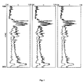
- the figure 5 represents, for lighting angles of -10 °, 0 ° and 10 °, the result of the radon transformation ("slant stack") of the shooting point collections composing the "walkaway" data.
- Step 2 Determination of a priori information about the dip of the deposits inside the target
- dip direction concerning the structuring of the impedance distribution (note that this direction can depend on the point that is to say the torque (x, z) considered), and we define a dip direction concerning the structuring of the boundary condition (note that the direction may depend on the point that is to say the couple (x, t) considered).
- Step 3 Simultaneous search for the impedance distribution I ( x, z ) within the target and boundary conditions B p ( x, t ) per illumination angle;
- This search is performed by minimizing, on all the angles of illumination considered, the difference between the data by illumination angle D p , and the seismic response of the target.
- This seismic response is considered as a function of this impedance distribution I ( x, z ) and of the boundary condition B p ( x , t ) for the lighting angle p considered: O ⁇ F I x ⁇ z , B p x ⁇ t
- D p corresponds to the measured seismic data
- O ° F ( I ( x, z ), B p ( x, t )) corresponds to these calculated data as a function of the unknowns I ( x, z ) and B p ( x, t ).
- This minimization is performed by taking into account the information a priori available (step 2), concerning I ( x, z ) and B p ( x, t ).
- a priori available (step 2), concerning I ( x, z ) and B p ( x, t ).
- the figure 8 shows the residuals associated with illumination angles of -10 °, 0 ° and 10 °.
- the gain applied for the graphical representation is the same as that used for the figure 5 .
- the figure 9 shows the boundary conditions found for angles of illumination of -10 °, 0 ° and 10 °. These boundary conditions satisfy the condition of regularity depending on the angle of illumination.
- the numerous disagreements between the result and the regularity condition integrated in the functional least squares illustrate the robustness of the method provided that the weights of regularization have been well chosen.
- Illustrated residues figure 8 appear negligible, despite significant differences with respect to the a priori information specified concerning the boundary conditions found ( figure 9 ): the values chosen for the two types of weights managed properly the conflicts between the various manipulated information (seismic data by angle of illumination, information a priori on the structuring of the distribution of impedance, information a priori on the structuring of the conditions to the limits).
- other boundary conditions are used than those of Dirichlet at the roof of the tank.
- lightings are used by wave fields consisting of non-planar wave fronts.
- step b of step 1 illumination angle data.
- This strategy has the advantage of simplicity both in the presentation and in the implementation. But this choice is in no way limiting: the important point is to be able to predict the shape of the wave fronts illuminating the target and to be able to take into account this information a priori.
- the method is used to estimate the distribution of impedances S (and no longer impedance P), the propagation speed distribution of the S waves having been previously estimated.
- the transposition of the method for this purpose is immediate when we have a seismic source exciting the SH mode (which requires placing the source in a solid medium, as opposed to sources used in marine seismics).
- the transverse displacement field or displacement velocity is still a solution of the wave equation in which the S wave propagation velocity and the S impedance appear.
- the method according to the invention provides an image of the target zone of the subsoil, representing the estimated impedance distribution ( figure 6 ).
- This result is both high resolution and quantitative.
- the vertical resolution of the impedance distribution obtained provides very detailed information on the desired distribution ( figure 7 ).
- This vertical resolution is far superior to that of conventional methods, such as data migration figure 11 .
- the figure 11 shows the result obtained by migration depth before summation of the data.
- the image is tainted by distortions (curvature of the layers, events arising from the imaging of multiple reflections) and shows a vertical resolution very much lower than the result of the figure 6 .
- geophysicists use measurements made in wells (logs, coring). These logs generally offer precise measurements, particularly in terms of resolution, but whose relevance is limited to the immediate vicinity of the well (typically one meter). These measurements are essential to know the lithology and the petrophysical properties of the crossed layers.
- the invention can be seen as a new type of logging, with certainly a lower vertical resolution than traditional logging, but with the advantage of considerably widening the vicinity of the well being investigated and even providing an estimate of the lateral variations to inside this neighborhood.
- the result of the invention can be used as it is, or serve as an entry point into seismic data processing and interpretation software (stratigraphic deconvolution, inversion of seismic data).
- temporal variations in the impedance distribution estimated by the method can be used to detect changes in the petrophysical properties of the reservoir, for example to optimize its production, or its coverage, in order to foresee the risk of accidents.
Abstract
Description
La présente invention concerne le domaine de l'exploration du sous-sol à partir de données sismiques.The present invention relates to the field of exploration of the subsoil from seismic data.
L'invention concerne notamment un traitement de données sismiques, permettant de fournir une image haute résolution du sous-sol. Une telle image est utilisée dans le domaine de l'exploration et la production pétrolière, ou le domaine de la surveillance de sites géologiques de stockage de CO2.The invention particularly relates to a seismic data processing, to provide a high resolution image of the subsoil. Such an image is used in the field of oil exploration and production, or the field of monitoring geological CO 2 storage sites.
Dans l'industrie pétrolière et pour la surveillance des sites de stockage de CO2, il est très important de disposer d'images précises du sous-sol. La précision est définie en terme de résolution. Plus la résolution est haute, plus l'image contient d'informations sur la structure, voire la composition, du sous-sol. On recherche donc, dans ces domaines, à construire des images « haute résolution » du sous-sol, qu'il soit considéré comme statique (cas de l'exploration pétrolière) ou dynamique (cas du monitoring ou de la surveillance des réservoirs souterrains).In the oil industry and for the monitoring of CO 2 storage sites, it is very important to have accurate images of the subsoil. Precision is defined in terms of resolution. The higher the resolution, the more the image contains information about the structure, or even the composition, of the subsoil. In these areas, we are therefore seeking to construct "high resolution" images of the subsoil, whether it is static (in the case of oil exploration) or dynamic (in the case of monitoring or monitoring underground reservoirs). .
Pour établir une image du sous-sol, on réalise des mesures au sein de celui-ci. Deux grands types de mesures sont classiquement utilisés : des mesures au sein de puits forés à travers la formation, et des campagnes sismiques. Les premières permettent de parfaitement définir les propriétés du sous-sol, soit par des carottages, soit par des diagraphies (mesures de différentes propriétés du sous-sol en continue le long du puits) puis interprétations de ces diagraphies. L'information est précise, mais très localisée autours du puits. En revanche, les données sismiques jouent un rôle privilégié en imageant un grand volume du sous-sol. Mais l'information est moins précise, la résolution moins bonne.To establish an image of the subsoil, measurements are made within it. Two main types of measurements are conventionally used: measurements within boreholes drilled through training, and seismic surveys. The first ones make it possible to perfectly define the properties of the subsoil, either by cores, or by logs (measurements of different properties of the subsoil in continuous along the well) then interpretations of these logs. The information is accurate, but very localized around the well. On the other hand, the seismic data plays a privileged role by imagining a large volume of the subsoil. But the information is less precise, the resolution less good.
Cependant, de nombreuses techniques ont été développées pour améliorer la précision de l'information issue des données sismiques. En particulier, les méthodes sismiques d'imagerie quantitative, qui visent à estimer la distribution de certains paramètres dans le sous-sol, tels que l'impédance acoustique ou des paramètres liés à l'impédance, apparaissent comme une avancée significative par rapport à l'obtention d'une image sismique conventionnelle. Bien entendu la qualité du résultat fourni par ces méthodes est d'autant plus grande que la résolution de l'image issue directement des données sismiques est haute.However, many techniques have been developed to improve the accuracy of information from seismic data. In particular, seismic quantitative imaging methods, which aim to estimate the distribution of certain parameters in the subsoil, such as acoustic impedance or impedance related parameters, appear as a significant advance over the obtaining a conventional seismic image. Of course the quality of the result provided by these methods is all the greater as the resolution of the image directly from the seismic data is high.
Entre ces deux grands types de mesures, il existe des méthodes d'acquisition de données sismiques de puits. Il s'agit d'émettre des ondes sismiques dans le sous-sol, et d'enregistrer la réponse (réflexions notamment) du sous-sol au moyen de récepteurs placés dans un puits.Between these two major types of measurements, there are methods of acquiring well seismic data. This is to emit seismic waves in the basement, and to record the response (reflections in particular) of the subsoil by means of receptors placed in a well.
Parmi ces techniques de sismiques de puits, on connaît la méthode d'acquisitions de type « ballade sismique » plus connu sous le nom de "walkaway". Cette technique est décrite par exemple dans :
-
Mari, J.L., Glangeaud F., Coppens F., 1997, "Traitement du signal pour géologues et géophysisciens", editions Technip
-
Mari, JL, F. Glangeaud, F. Coppens, 1997, "Signal Processing for Geologists and Geophysicists," Technip Editions
Comme l'illustre la
La
Mais cette approche repose sur une vision 1 D de la propagation des ondes, ce qui n'est pas vraiment réaliste surtout pour des données où la source n'est pas à l'aplomb du puits.But this approach is based on a 1D vision of the propagation of waves, which is not really realistic especially for data where the source is not in line with the well.
Dès que la propagation des ondes s'effectue suivant des directions autres que la verticale, une estimation de la distribution de vitesse est essentielle pour effectuer le traitement. Dans l'hypothèse où la terre est considérée comme un milieu 1 D, des extensions au traitement présenté ci-dessus ont été proposées : ces extensions reposent sur l'application de corrections dynamiques (corrections de déport alias NMO).As soon as wave propagation takes place in directions other than vertical, an estimate of the velocity distribution is essential to perform the treatment. Assuming that the earth is considered as a 1D medium, extensions to the treatment presented above have been proposed: these extensions are based on the application of dynamic corrections (offset corrections aka NMO).
Mais ce concept ne permet pas de prendre en compte les événements sismiques engendrés par les arrivées secondaires. En effet, la correction à appliquer à ces événements n'a rien d'intrinsèque et dépend de l'événement. S'il n'y avait pas d'arrivées secondaires et, de façon plus générale pas de réflexions multiples, hypothèse peu réaliste, l'imagerie des données sismiques de puits pourrait être réalisée par une simple migration des enregistrements, la distribution de vitesse ayant été préalablement estimée. On obtiendrait ainsi, pour peu que certaines précautions aient été prises, une estimation de la réflectivité (quantité liée à l'impédance) du sous-sol. Cependant, l'illumination particulière du milieu (liée à un dispositif d'acquisition localisé dans un puits) fait que le résultat est entaché de distorsions, comme l'illustre la
Le document suivant présente les techniques connues de traitement de données de sismique de puits :
Ainsi, les techniques antérieures ont du mal à concilier prise en compte des réflexions multiples et propagation multidimensionnelle, et a fortiori, dans des milieux autres que des milieux 1D. Par ailleurs, ces techniques d'imagerie utilisent des processus linéaires (déconvolution ou migration), ayant pour conséquence de limiter la résolution des images sismiques à la bande de fréquence de la sismiques (de l'ordre de λ/2 si λ est la longueur d'onde sismique).Thus, prior techniques have difficulty in reconciling multiple reflections and multidimensional propagation, and even more so in environments other than 1D environments. Moreover, these imaging techniques use linear processes (deconvolution or migration), having the consequence of limiting the resolution of the seismic images to the frequency band of the seismic (of the order of λ / 2 if λ is the length seismic wave).
L'objet de la présente invention est une méthode pour construire une image du sous-sol en prenant en compte, tant les réflexions multiples que le caractère multidimensionnel de la propagation. De plus, par l'utilisation d'une technique d'imagerie non linéaire, l'invention permet d'améliorer sensiblement la résolution verticale, et notamment d'aller bien au delà de la bande de fréquence de la sismique (de λ/2 à λ/10 en fonction de l'hétérogénéité des sédiments).The object of the present invention is a method for constructing an image of the subsoil taking into account both the multiple reflections and the multidimensional nature of the propagation. Moreover, by the use of a non-linear imaging technique, the invention makes it possible to substantially improve the vertical resolution, and in particular to go well beyond the frequency band of the seismic (of λ / 2 at λ / 10 depending on the heterogeneity of the sediments).
L'objet de l'invention concerne une méthode pour construire une image représentative d'une distribution d'impédances acoustiques dans une zone du sous-sol, au moyen de mesures sismiques acquises selon une configuration comportant une émission d'ondes sismiques depuis la surface dans le sous-sol et la réception par des récepteurs positionnés à différentes profondeurs dans au moins un puits. La méthode nécessite également une estimation du champ de vitesse de propagation d'ondes sismiques dans le sous-sol. La méthode comporte les étapes suivantes :
- on sélectionne p angles d'éclairage, chaque angle d'éclairage correspondant à une direction de propagation d'un front d'onde au niveau d'une limite supérieure de ladite zone ;
- on organise lesdites mesures sismiques, en des données Dp organisées par angle d'éclairage p ;
- on détermine, à l'intérieur de ladite zone, ladite distribution d'impédances acoustiques au moyen d'une inversion, au cours de laquelle on minimise un écart entre lesdites données organisées Dp issues desdites mesures sismiques, et de données issues d'une estimation par résolution d'une équation de propagation des ondes à partir dudit champ de vitesses, d'une distribution d'impédance acoustique, et d'une distribution de pression au niveau de ladite limite supérieure de la zone pour chaque angle d'éclairage.
- p illumination angles are selected, each illumination angle corresponding to a propagation direction of a wavefront at an upper limit of said zone;
- said seismic measurements are organized into data D p organized by illumination angle p ;
- within said zone, said distribution of acoustic impedances is determined by means of an inversion, during which a difference between said organized data D p originating from said seismic measurements is minimized, and data obtained from a resolution estimation of a wave propagation equation from said velocity field, acoustic impedance distribution, and pressure distribution at said upper boundary of the zone for each illumination angle.
Pour minimiser l'écart, on peut prendre en compte une information a priori définie par une direction de pendage concernant une structuration de la distribution d'impédance acoustique, et une direction de pendage concernant une structuration de la distribution de pression. Pour ce faire, on peut minimiser une fonctionnelle des moindres carrés comportant : un premier terme mesurant ledit écart, un second terme correspondant à une dérivée directionnelle concernant la structuration de la distribution d'impédance acoustique et pondéré par un poids ε I , et un troisième terme correspondant à une dérivée directionnelle concernant la structuration de la distribution de pression et pondéré par un poids ε B,p . Les poids peuvent être déterminés par une technique d'essais-erreurs. On peut également appliquer les règles suivantes :
- un résultat faisant apparaître des résidus corrélés trop forts, traduit une valeur trop forte d'au moins un des deux types de poids ;
- un résultat faisant apparaître une distribution d'impédance acoustique avec des variations latérales anormalement faibles, traduit une valeur trop forte accordée au poids ε I.
- a result showing correlated residues that are too strong, reflects an excessively high value of at least one of the two types of weight;
- a result showing an acoustic impedance distribution with abnormally low lateral variations, reflects a too strong value given to the weight ε I.
Selon l'invention, on peut ajouter un terme à la fonctionnelle, pour prendre en compte une information a priori déterminée au niveau d'au moins un puits forés au travers de la zone.According to the invention, a term can be added to the functional, to take into account information a priori determined at the level of at least one well drilled through the zone.
Pour organiser les données sismiques en données pas angle d'éclairage, on peut utiliser une transformation de Radon.To organize the seismic data into no lighting angle data, one can use a Radon transformation.
Selon l'invention, on peut interpréter l'image en termes lithologiques et/ou pétrophysiques, de façon à surveiller un site de stockage géologique de gaz acides, ou de façon à localiser et évaluer des réservoirs pétroliers. On peut également utiliser l'image en complément d'autres diagraphies pour caractériser la zone.According to the invention, the image can be interpreted in lithological and / or petrophysical terms, so as to monitor a geological acid gas storage site, or in order to locate and evaluate oil reservoirs. The image can also be used in addition to other logs to characterize the area.
D'autres caractéristiques et avantages de la méthode selon l'invention, apparaîtront à la lecture de la description ci-après d'exemples non limitatifs de réalisations, en se référant aux figures annexées et décrites ci-après.Other characteristics and advantages of the method according to the invention will appear on reading the following description of nonlimiting examples of embodiments, with reference to the appended figures and described below.
-
La
figure 1 illustre la configuration d'acquisition de type "walkaway".Thefigure 1 illustrates the "walkaway" acquisition configuration. -
La
figure 2 représente une distribution de vitesse des ondes dans le sous-sol, selon une direction X et la profondeur Z.Thefigure 2 represents a velocity distribution of the waves in the basement, in a direction X and the depth Z. -
La
figure 3 représente une distribution d'impédance acoustique dans le sous-sol, selon une direction X et la profondeur Z.Thefigure 3 represents an acoustic impedance distribution in the basement, in a direction X and the depth Z. -
La
figure 4 représente trois collections point de tir (associées à des sources localisées en x = -315, x = 0 et x = + 315 m) extraites des données "walkaway".Thefigure 4 represents three point-of-fire collections (associated with sources located in x = -315, x = 0 and x = + 315 m) extracted from walkaway data. -
La
figure 5 représente, pour des angles d'éclairage de -10°, 0° et 10°, le résultat de la transformation de Radon ("slant stack") des collections points de tir composant les données "walkaway" de lafigure 4 .Thefigure 5 represents, for lighting angles of -10 °, 0 ° and 10 °, the result of the radon transformation ("slant stack") of the shooting point collections composing the "walkaway" data of thefigure 4 . -
La
figure 6 montre la distribution d'impédance retrouvée.Thefigure 6 shows the found impedance distribution. -
La
figure 7 compare trois profils d'impédance (I) extraits desfigures 3 et6 pour x = 0, x = 40 et x = 200 m.Thefigure 7 compares three impedance profiles (I) extracted fromfigures 3 and6 for x = 0, x = 40 and x = 200 m. -
La
figure 8 montre les résidus associés à des angles d'éclairage de -10°, 0° et 10°.Thefigure 8 shows the residuals associated with illumination angles of -10 °, 0 ° and 10 °. -
La
figure 9 montre les conditions aux limites retrouvées pour des angles d'éclairage de - 10°, 0° et 10°.Thefigure 9 shows the boundary conditions found for illumination angles of -10 °, 0 ° and 10 °. -
La
figure 10 compare les modules des transformées de Fourier des parties profondes (c'est-à-dire pour z allant de 2000 m à 3400 m) des profils d'impédance représentés sur lafigure 7 et des traces correspondantes de la section migrée.Thefigure 10 compares the Fourier transform modules of the deep portions (i.e. for z ranging from 2000 m to 3400 m) of the impedance profiles represented on thefigure 7 and corresponding traces of the migrated section. -
La
figure 11 montre le résultat obtenu par migration profondeur avant sommation des données.Thefigure 11 shows the result obtained by migration depth before summation of the data.
Pour des raisons de clarté, la méthode est décrite dans un contexte 2D, la généralisation à trois dimensions étant immédiate.For the sake of clarity, the method is described in a 2D context, the three-dimensional generalization being immediate.
On appelle « cible », la partie du sous-sol que l'on souhaite caractériser par une image haute résolution, au moyen d'une acquisition de données sismiques de type « walkaway » (
Soit une cible bidimensionnelle caractérisée par les distributions d'impédance et de vitesse représentées respectivement sur les
La
La
Ainsi, à partir de la distribution de vitesse de propagation des ondes P dans le sous-sol préalablement estimée, et des données de type "walkaway" acquises, la méthode vise à reconstruire une distribution d'impédance acoustique.Thus, from the P-wave propagation velocity distribution in the previously estimated subsoil, and acquired "walkaway" type data, the method aims to reconstruct an acoustic impedance distribution.
Pour déterminer cette image haute résolution, la méthode comporte une recherche simultanée de la distribution d'impédance à l'intérieur de la cible et des excitations sismiques par angle d'éclairage. Cette recherche se fait par résolution d'un problème inverse. Avant de décrire le problème inverse, le problème direct qui lui est associé est décrit.To determine this high-resolution image, the method involves a simultaneous search for the impedance distribution inside the target and seismic excitations by illumination angle. This search is done by solving an inverse problem. Before describing the opposite problem, the direct problem associated with it is described.
On considère l'équation des ondes acoustiques décrivant, à partir de conditions initiales nulles, l'évolution, partant d'un état initial où le milieu est au repos, du champ de pression en fonction du temps à l'intérieur de la cible. Le champ de vitesse étant connu, ce champ de pression P(x,z,t) est complètement décrit une fois spécifiées :
- la distribution d'impédance acoustique I(x,z);
- la condition aux limites au toit de la cible. Selon un exemple de réalisation, on utilise une condition aux limites de type Dirichlet, la valeur de la pression au toit de la cible en fonction de coordonnée latérale x et du temps t. On note cette condition aux limites B(x,t). Cette condition aux limites caractérise l'éclairage de la cible.
- the acoustic impedance distribution I (x, z);
- the boundary condition at the roof of the target. According to an exemplary embodiment, a boundary condition of the Dirichlet type is used, the value of the roof pressure of the target as a function of lateral coordinate x and of time t . This condition is noted at the limits B ( x, t ). This boundary condition characterizes the lighting of the target.
De façon précise, P est solution de l'équation des ondes qui s'écrit (c(x,z) désigne la distribution de vitesse de propagation) : 
avec la condition aux limites : P = B(x, t) au toit de la cible
et les conditions initiales : P = 0 pour t ≤ 0Specifically, P is the solution of the wave equation that is written ( c ( x , z ) denotes the propagation velocity distribution):
with the boundary condition: P = B ( x, t ) at the roof of the target
and the initial conditions: P = 0 for t ≤ 0
Cette équation des ondes acoustiques correspond à l'équation d'évolution en temps (par opposition à l'écriture dans le domaine des fréquences temporelles conduisant à l'équation d'Helmholtz) et, de surcroît, dans sa forme la plus simple, notamment sans prendre en compte l'atténuation. Des modifications dans l'écriture de l'équation des ondes ne demandent que l'adaptation de la méthode numérique utilisée pour sa résolution (et pour le calcul du gradient de la fonctionnelle des moindres carrés si l'on utilise une méthode d'optimisation basée sur ce calcul).This equation of acoustic waves corresponds to the equation of evolution in time (as opposed to the writing in the domain of the temporal frequencies leading to the Helmholtz equation) and, moreover, in its simplest form, in particular without taking into account the attenuation. Changes in the writing of the wave equation request that the adaptation of the numerical method used for its resolution (and for the calculation of the least-squares functional gradient if one uses an optimization method based on this calculation).
Le fait que le champ de pression à l'intérieur de la cible soit complètement déterminé, une fois spécifiées la distribution d'impédance et la condition aux limites au toit de la cible, permet de considérer le champ de pression à l'intérieur de la cible comme une fonction de I(x, z) et de B(x,t), et amène à introduire l'opérateur de modélisation F suivant : ![]()
![]()
On note que l'opérateur F est non linéaire en la distribution d'impédance. Par conséquent, pour une condition aux limites donnée, la réponse sismique à la somme de deux distributions d'impédance n'est pas la somme des réponses sismiques associées à chaque distribution d'impédance. En pratique on a besoin d'évaluer, pour des couples(I(x,z),B(x,t)) donnés, l'image par F de ces couples : cette opération est réalisée par résolution numérique de l'équation des ondes, par la méthode des différences finies (par exemple K. R. Kelly, et al., 1976, « Synthetic seismograms: a finite - difference approach", Geophysics, 41, 2), ou la méthode des éléments finis (par exemple Kurt J. Marfurt, 1984, « Accuracy of finite - difference and finite - element modeling of the scalar and elastic wave equations", Geophysics, 49, 533).It is noted that the operator F is non-linear in the impedance distribution. Therefore, for a given boundary condition, the seismic response to the sum of two impedance distributions is not the sum of the seismic responses associated with each impedance distribution. In practice we need to evaluate, for given pairs ( I ( x, z ), B ( x, t )), the image by F of these pairs: this operation is carried out by numerical resolution of the equation of waves, by the finite difference method (eg KR Kelly, et al., 1976, "Synthetic seismograms: a finite-difference approach", Geophysics, 41, 2), or the finite element method (eg Kurt J. Marfurt, 1984, "Accuracy of finite - difference and finite - element modeling of the scalar and elastic wave equations", Geophysics, 49, 533).
Considérant désormais le problème inverse associé :Considering now the opposite problem associated:
Grâce aux données de type "walkaway", nous disposons de mesures liées au champ de pression dans la cible. Selon un exemple on utilise les composantes u x (t) et uz (t) de la vitesse de déplacement engendré par le champ de pression. Ces vitesses sont directement mesurées si l'on utilise des géophones comme récepteurs. On pourrait également utiliser une mesure portant sur une dérivée ou une intégrale en temps de ces quantités (par exemple accélération ou bien le déplacement lui-même). On pourrait également utiliser directement la pression mesurée au capteur, si ce dernier est un hydrophone.Thanks to walkaway data, we have measurements related to the pressure field in the target. According to one example, the components u x ( t ) and u z ( t ) of the speed of displacement generated by the pressure field are used. These speeds are directly measured if geophones are used as receivers. One could also use a measurement relating to a derivative or an integral in time of these quantities (for example acceleration or the displacement itself). One could also directly use the measured pressure sensor, if the latter is a hydrophone.
On note Dp le vecteur de données pour chaque angle d'éclairage p. Soit O l'opérateur d'observation, c'est-à-dire l'opérateur qui, au champ de pression à l'intérieur de la cible P(x,z,t), associe les mesures Dp. On peut par exemple utiliser les équations d'Euler pour cet opérateur O : 


Le problème inverse consiste à déterminer la distribution d'impédance acoustique I(x,z) et les différentes conditions aux limites Bp (x,t), à partir de la collection des différents Dp. The inverse problem consists in determining the acoustic impedance distribution I ( x, z ) and the different boundary conditions B p ( x, t ), from the collection of the different D p .
La méthode comporte principalement les étapes suivantes :
- 1. Construction de collection de données Dp pour chaque angle d'éclairage
- a. sélection d'une suite d'angles d'éclairage de la cible ;
- b. transformation des collections point de tir en des données par angle d'éclairage ;
- 2. Détermination d'une information a priori concernant le pendage des dépôts à l'intérieur de la cible ;
- 3. Recherche simultanée de I(x,z) à l'intérieur de la cible et des différentes conditions aux limites Bp (x,t) par angle d'éclairage ;
- 1. Data collection construction D p for each lighting angle
- at. selecting a sequence of lighting angles of the target;
- b. transformation of point of fire collections into data by lighting angle;
- 2. Determination of a priori information concerning the dip of the deposits inside the target;
- 3. Simultaneous search of I ( x, z ) within the target and the different boundary conditions B p ( x, t ) by illumination angle;
On appelle « angle d'éclairage », la direction de propagation d'un front d'onde au toit de la cible. En deux dimensions, cette direction est définie par l'angle fait avec la verticale. En trois dimensions, "l'angle d'éclairage" est défini par une pente (l'angle fait avec la verticale) et un azimut.The "direction of illumination" is the direction of propagation of a wavefront at the roof of the target. In two dimensions, this direction is defined by the angle made with the vertical. In three dimensions, the "angle of illumination" is defined by a slope (the angle made with the vertical) and an azimuth.
De façon à conserver la même quantité d'information lors de l'étape suivante de transformation des collections point de tir en collections par classe d'angle d'éclairage, on sélectionne autant d'angles que de point de tirs (mais ce choix n'est pas essentiel). Selon un exemple, les angles sélectionnés couvrent l'intervalle -10°, +10°. L'interprétation de la sismique de surface révélant une structure quasi 1 D, il est naturel de sélectionner des angles d'éclairage centrés sur 0°.In order to keep the same amount of information in the next step of transforming point-of-fire collections into collections by lighting angle class, we select as many angles as shotpoints (but this choice is not essential). In one example, the selected angles cover the range -10 °, + 10 °. Since the interpretation of surface seismic reveals a quasi-1D structure, it is natural to select illumination angles centered on 0 °.
Pour chacun des angles d'éclairage sélectionnés, on transforme les collections point de tir en des données par angle d'éclairage.For each of the selected lighting angles, the point of fire collections are transformed into data by lighting angle.
Les collections point de tir sont les données brutes issues de l'acquisition de type « walkaway ». Il s'agit d'une organisation des données bien connue des spécialistes.Point of fire collections are the raw data from the walkaway acquisition. This is a data organization well known to specialists.
Ces données par angle d'éclairage, notées Dp , sont définies comme la réponse sismique de la cible à une excitation sismique par angle d'éclairage, correspondant à un champ d'onde qui, vu au niveau du (des) récepteur(s) le(s) moins profond(s), serait constitué d'une succession de fronts d'ondes correspondant à peu près à l'angle d'éclairage spécifié.These data by illumination angle, denoted D p , are defined as the seismic response of the target to a seismic excitation by illumination angle, corresponding to a wave field which, seen at the level of the receiver (s) ) the shallower (s), would consist of a succession of wavefronts corresponding to approximately the specified illumination angle.
L'idée de base est d'effectuer une transformation de Radon sur les collections point de tir (technique appelée "slant stack"). Une telle technique est décrite par exemple dans les documents suivants :
-
L. Lu and G. F. Gardner, 1991, "Slant-Stack Processing", SEG Books, 1 -
J.F. Clarbout, 1985, "Imaging the earth's interior", Blackwell scientific publications
-
L. Lu and GF Gardner, 1991, "Slant-Stack Processing", SEG Books, 1 -
JF Clarbout, 1985, "Imaging the earth's interior", Blackwell scientific publications
Cette technique vise à transformer la réponse sismique mesurée en un capteur pour différentes positions de la source sismique, en la réponse à une excitation onde plane se propageant depuis la surface suivant une direction donnée. Cette technique a été mise en oeuvre pour obtenir les collections par angle représentées sur la
Dans ce cas, l'angle d'éclairage est en général différent de l'angle défini pour la mise en oeuvre du "slant stack", mais la relation entre l'un et l'autre peut être calculée par exemple par un tracé de rayons par onde plane. Dans le cas d'importantes variations latérales de vitesse de propagation dans le milieu au dessus de la cible, l'onde plane envoyée en surface peut s'être notablement déformée lors de son arrivée sur le toit de la cible. Dans ce cas il est préférable d'utiliser une approche plus raffinée telle que la technique d'illumination contrôlée décrite dans le document suivant :
-
W. E. A. Rietveld and A. J. Berkhout, 1994, "Prestack depth migration by means of controlled illumination", Geophysics, 59, 801
-
WEA Rietveld and AJ Berkhout, 1994, "Prestack depth migration by means of controlled illumination", Geophysics, 59, 801
Cette information est fournie par une interprétation (pointé sismique) sur la sismique de surface, des événements sismiques correspondant aux couches sédimentaires constituant la cible. Selon un exemple, on considère comme modèle a priori un modèle stratifié horizontalement. On rappelle, pour l'extension au cas 3D, qu'en 3D un pendage est défini par une pente et un azimut. Ces informations sur les pendages caractérisent :
- la structuration lithologique de la distribution d'impédance acoustique ; et
- la structuration des différentes conditions aux limites.
- the lithological structuring of the acoustic impedance distribution; and
- the structuring of different boundary conditions.
Ces fonctions (impédance ou conditions aux limites) sont censées varier doucement suivant des directions qui peuvent être prédites à l'avance (et qui, pour les conditions aux limites, dépendent de l'angle d'éclairage p ).These functions (impedance or boundary conditions) are supposed to vary slowly in directions that can be predicted in advance (and which, for boundary conditions, depend on the illumination angle p ).
Ainsi, on définit une direction de pendage concernant la structuration de la distribution d'impédance (notons que cette direction peut dépendre du point c'est-à-dire du couple (x,z) considéré), et on définit une direction de pendage concernant la structuration de la condition aux limites (notons que la direction peut dépendre du point c'est-à-dire du couple (x,t) considéré).Thus, we define a dip direction concerning the structuring of the impedance distribution (note that this direction can depend on the point that is to say the torque (x, z) considered), and we define a dip direction concerning the structuring of the boundary condition (note that the direction may depend on the point that is to say the couple (x, t) considered).
On recherche simultanément la distribution d'impédance I(x,z) (ou tout autre paramètre lié à l'impédance) à l'intérieur de la cible, et les différentes conditions aux limites Bp (x,t) par angle d'éclairage (excitations sismiques).Simultaneously search distribution impedance I (x, z) (or any other parameter related to the impedance) within the target, and various boundary conditions B p (x, t) by angle lighting (seismic excitations).
Cette recherche est effectuée en minimisant, sur l'ensemble des angles d'éclairage considérés, l'écart entre les données par angle d'éclairage Dp , et la réponse sismique de la cible. Cette réponse sismique est considérée comme fonction de cette distribution d'impédance I(x,z) et de la condition aux limites Bp (x,t) pour l'angle d'éclairage p considéré : ![]()
![]()
Ainsi Dp correspond aux données sismiques mesurées, et O°F(I(x,z),Bp (x,t)) correspond à ces données calculées en fonction des inconnues I(x,z) et Bp (x,t).Thus D p corresponds to the measured seismic data, and O ° F ( I ( x, z ), B p ( x, t )) corresponds to these calculated data as a function of the unknowns I ( x, z ) and B p ( x, t ).
Cette minimisation est réalisée en prenant en compte l'information a priori disponible (étape 2), concernant I(x,z) et Bp (x,t). On peut quantifier l'écart par rapport à ces informations a priori, suivant une technique d'évaluation de la norme L 2 de dérivées directionnelles portant sur les fonctions concernées : I(x,z) ou Bp (x,t).This minimization is performed by taking into account the information a priori available (step 2), concerning I ( x, z ) and B p ( x, t ). We can quantify the difference with respect to this information a priori, according to a technique of evaluation of the norm L 2 of directional derivatives relating to the functions concerned: I ( x, z ) or B p ( x , t ).
On recherche donc la distribution d'impédance acoustique I(x,z) et les conditions aux limites Bp (x,t) associées aux différents angles d'éclairage qui expliquent au mieux les données Dp tout en satisfaisant les informations a priori.We are therefore looking for the acoustic impedance distribution I ( x , z ) and the boundary conditions B p ( x, t ) associated with the different illumination angles which best explain the data D p while satisfying the prior information.
Pour ce faire, on peut rechercher ces quantités comme réalisant le minimum de la fonctionnelle des moindres carrés : 
où :
- {Bp } désigne l'ensemble des conditions aux limites que l'on se propose de retrouver pour chaque angle d'éclairage p ;
- ∥ ∥ D,p désigne la norme dans l'espace des données pour l'angle d'éclairage p ;
- ∥ ∥ désigne la norme de type L 2 éventuellement pondérée (ou euclidienne si l'on s'intéresse à des quantités discrètes) dans l'espace des fonctions définies sur la zone cible
- le symbole ∂ I désigne la dérivée directionnelle choisie lors de la spécification de l'information a priori concernant la structuration de la distribution d'impédance (notons que la direction peut dépendre du point c'est-à-dire du couple (x,z) considéré);
- ∥ ∥ B,p désigne la norme de type L 2 éventuellement pondérée (ou euclidienne si l'on s'intéresse à des quantités discrètes) dans l'espace des fonctions de x et de t où sont définies les conditions aux limites pour l'angle d'éclairage p;
- le symbole ∂ p désigne la dérivée directionnelle choisie lors de la spécification de l'information a priori concernant la structuration de la condition aux limites (notons que la direction peut dépendre du point c'est à dire du couple (x,t) considéré);
- ε I désigne un poids de régularisation traduisant la confiance que l'on accorde à l'information a priori concernant la structuration de la distribution d'impédance
- ε B,p désigne un poids de régularisation traduisant la confiance que l'on accorde à l'information a priori concernant la structuration de la condition aux limites.
or :
- { B p } denotes the set of boundary conditions that we propose to find for each lighting angle p ;
- ∥ ∥ D, p is the standard in the data space for the illumination angle p ;
- ∥ ∥ designates the L 2 -type norm possibly weighted (or Euclidean if one is interested in discrete quantities) in the space of the functions defined on the target zone
- the symbol ∂ I denotes the directional derivative chosen during the specification of the prior information concerning the structuring of the impedance distribution (note that the direction may depend on the point that is to say the torque ( x, z ) considered);
- ∥ ∥ B, p denotes the type L 2 possibly weighted norm (Euclidean or if one is interested in discrete amounts) into the space functions x and t, where the boundary conditions are defined for the lighting angle p ;
- the symbol ∂ p designates the directional derivative chosen during the specification of the prior information concerning the structuring of the boundary condition (note that the direction may depend on the point, ie on the torque ( x , t ) considered) ;
- ε I denotes a weight of regularization expressing the confidence that one grants to the information a priori concerning the structuring of the distribution of impedance
- ε B, p denotes a regularization weight expressing the confidence that is given to the information a priori concerning the structuring of the boundary condition.
La recherche de ce minimum peut être mise en oeuvre en utilisant les techniques classiques de l'optimisation telles que décrites par exemple dans le document suivant :
-
J. Nocedal and S. J. Wright, 1999, "Numerical Optimization", Springer
-
J. Nocedal and Wright SJ, 1999, "Numerical Optimization", Springer
A titre d'exemple, on peut déterminer le minimum de la fonctionnelle des moindres carrés par les méthodes d'optimisation appelées méthodes de descente : ces méthodes itératives construisent une suite de "couples" (I,{Bp }) faisant décroître la valeur de la fonctionnelle, la construction de l'itéré suivant se faisant en exploitant le gradient de la fonctionnelle à l'itéré considéré.For example, we can determine the minimum of the least squares function by the optimization methods called descent methods: these iterative methods construct a series of "couples" ( I , { B p }) decreasing the value of the functional, the construction of the iterated following being done exploiting the gradient of the functional to the iterated considered.
Concernant le choix des poids de régularisation ε I et εB.p, il peut se faire par essai-erreur, guidé par la règle suivante : l'objectif est d'obtenir in fine une distribution d'impédance conforme aux attentes du sédimentologue, et des résidus (c'est-à-dire la différence Dp-O°F(I,Bp )) raisonnables du point de vue du géophysicien.Concerning the choice of regularization weights ε I and ε Bp , it can be done by trial-error, guided by the following rule: the objective is to obtain finally an impedance distribution in accordance with the expectations of the sedimentologist, and the residues (that is, the difference D p -O ° F ( I, B p )) reasonable from the point of view of the geophysicist.
Sur l'exemple présenté, en appliquant la méthode selon l'invention avec des valeurs identiques de ε B,p pour les différents p, on peut obtenir la distribution d'impédance représentée sur la
La
La
Les résidus illustrés
Pour parvenir à l'objectif visé, et corriger une mauvaise estimation des valeurs à affecter aux poids, on peut appliquer les règles suivantes :
- un résultat faisant apparaître des résidus corrélés trop forts, traduit une valeur trop forte d'au moins un des deux types de poids ;
- un résultat faisant apparaître une distribution d'impédance avec des variations latérales anormalement faibles, traduit une valeur trop forte accordée au poids ε I .
- a result showing correlated residues that are too strong, reflects an excessively high value of at least one of the two types of weight;
- a result showing an impedance distribution with abnormally low lateral variations, reflects a too strong value given to the weight ε I.
D'autres informations, telles que des diagraphies et la connaissance sédimentologique, peuvent être prises en compte comme information a priori. Ces données peuvent être utilisée par des termes additionnels intégrés dans la fonctionnelle des moindres carrés, via un paramétrage approprié, des contraintes permettant de limiter l'espace des distributions d'impédance, ...Other information, such as logging and sedimentological knowledge, can be taken into account as prior information. These data can be used by additional terms integrated in the least squares functional, via an appropriate parameterization, constraints allowing to limit the space of the distributions of impedance, ...
D'autres techniques pour intégrer l'information a priori peuvent être envisagées. Par exemple, on peut contraindre les quantités recherchées (distribution d'impédances et conditions aux limites) à satisfaire l'information a priori, au moyen d'un paramétrage n'autorisant que des distributions conformes à l'information a priori.Other techniques for integrating information a priori can be considered. For example, it is possible to constrain the sought quantities (distribution of impedances and boundary conditions) to satisfy the information a priori, by means of a parameter setting allowing only distributions in accordance with the information a priori.
Selon un mode de réalisation, on utilise d'autres conditions aux limites que celles de Dirichlet au toit du réservoir.According to one embodiment, other boundary conditions are used than those of Dirichlet at the roof of the tank.
On peut par exemple spécifier le train d'ondes descendantes par des conditions aux limites "absorbantes" non homogènes du type 
- B. Chalindar, 1988, « Conditions aux limites absorbantes appliquées à des problèmes hyperboliques intervenant en sismique », Thèse, Université de Saint Etienne.
- B. Chalindar, 1988, "Absorbent boundary conditions applied to hyperbolic problems occurring in seismic", Thesis, University of Saint Etienne.
On peut encore utiliser des conditions aux limites absorbantes d'ordre supérieur comme décrit dans
-
Robert W. Clayton and Björn Engquist, 1980, « Absorbing boundary conditions for wave - equation migration », Geophysics, 45, 895
-
Robert W. Clayton and Bjorn Engquist, 1980, "Absorbing boundary conditions for wave-equation migration," Geophysics, 45, 895
L'utilisation d'autres conditions aux limites ne demande que l'adaptation de la méthode numérique utilisée pour résoudre l'équation des ondes (et pour le calcul du gradient de la fonctionnelle des moindres carrés si l'on utilise une méthode d'optimisation basée sur ce calcul).The use of other boundary conditions only requires the adaptation of the numerical method used to solve the wave equation (and for the calculation of the least-squares functional gradient if we use an optimization method based on this calculation).
Selon un autre mode de réalisation, on utilise des éclairages par des champs d'ondes constitués de fronts d'onde non plans. Nous avons basé notre présentation en supposant un éclairage par des fronts d'ondes approximativement plans (étape b de l'étape 1 : données par angle d'éclairage). Cette stratégie a l'avantage de la simplicité tant dans la présentation que dans la mise en oeuvre. Mais ce choix n'est en aucune façon limitatif : le point important est de pouvoir prédire la forme des fronts d'ondes éclairant la cible et de pouvoir prendre en compte cette information a priori.According to another embodiment, lightings are used by wave fields consisting of non-planar wave fronts. We based our presentation on the assumption of approximately flat wavefront illumination (step b of step 1: illumination angle data). This strategy has the advantage of simplicity both in the presentation and in the implementation. But this choice is in no way limiting: the important point is to be able to predict the shape of the wave fronts illuminating the target and to be able to take into account this information a priori.
Enfin, selon un autre mode de réalisation, la méthode est utilisée pour l'estimation de la distribution d'impédances S (et non plus d'impédance P), la distribution de vitesse de propagation des ondes S ayant été préalablement estimée. La transposition de la méthode à cette finalité est immédiate dès lors que l'on dispose d'une source sismique excitant le mode SH (ce qui demande de placer la source dans un milieu solide, par opposition aux sources utilisées en sismique marine). En effet le champ de déplacement (ou de vitesse de déplacement) transverse est encore solution de l'équation des ondes dans laquelle apparaît la vitesse de propagation des ondes S et l'impédance S.Finally, according to another embodiment, the method is used to estimate the distribution of impedances S (and no longer impedance P), the propagation speed distribution of the S waves having been previously estimated. The transposition of the method for this purpose is immediate when we have a seismic source exciting the SH mode (which requires placing the source in a solid medium, as opposed to sources used in marine seismics). Indeed, the transverse displacement field (or displacement velocity) is still a solution of the wave equation in which the S wave propagation velocity and the S impedance appear.
La méthode selon l'invention fournit une image de la zone cible du sous-sol, représentant la distribution d'impédance estimée (
La résolution verticale fournie par la méthode dépend de la gamme de profondeurs considérées :
- au voisinage de l'intervalle de profondeur couvert par les récepteurs, la résolution est essentiellement gouvernée par la distance séparant deux récepteurs consécutifs ;
- en dessous, on perd, comme il est habituel en sismique réflexion, les composantes très basse fréquence de la distribution d'impédance mais la résolution verticale, même si elle est moins bonne que plus haut, reste exceptionnellement bonne et largement meilleure que celle fournie par les méthodes traditionnelles. Dans cette partie profonde, le gain en résolution s'explique par le caractère non linéaire de l'inversion réalisée (alors que les techniques d'imagerie classiques sont linéaires). L'opérateur de modélisation F est en effet non linéaire, et cette particularité le rend apte à modéliser les diffractions / réflexions multiples. Dans le cas de dépôts à forte hétérogénéité verticale, comme c'est généralement le cas pour les terrains sédimentaires, les effets de diffractions / réflexions multiples sont importants et les prendre en compte permet de gagner en résolution verticale et notamment de sortir de la limitation à la bande des fréquences sismiques inhérente aux méthodes conventionnelles. Le gain en résolution verticale est illustré sur la
figure 10 (la résolution est caractérisée par la largeur de bande du spectre d'amplitude). Lafigure 10 compare les modules des transformées de Fourier des parties profondes (c'est-à-dire pour z allant de 2000 m. à 3400 m.) des profils d'impédance représentés sur lafigure 7 , et des traces correspondantes de la section migrée (après conversion de ces résultats d'une profondeur exprimée en mètre à une profondeur exprimée en temps de propagation vertical aller-retour ). Ces transformées de Fourier ont été normalisées de façon à rendre comparables les amplitudes du pic le plus important situé au dessus de 5 Hz. On constate une augmentation très significative de la largeur de bande, révélatrice du gain en résolution verticale accessible par application de notre méthode.
- in the vicinity of the depth interval covered by the receivers, the resolution is essentially governed by the distance separating two consecutive receivers;
- below, we lose, as is usual in seismic reflection, the very low frequency components of the impedance distribution but the vertical resolution, even if it is less good than higher, remains exceptionally good and much better than that provided by traditional methods. In this deep part, the gain in resolution is explained by the nonlinear character of the inversion performed (whereas the classical imaging techniques are linear). The modeling operator F is indeed non-linear, and this feature makes it suitable for modeling multiple diffractions / reflections. In the case of deposits with high vertical heterogeneity, as is generally the case for sedimentary terrains, the effects of diffraction / multiple reflections are important and taking them into account makes it possible to gain in vertical resolution and in particular to get out of the limitation to the seismic frequency band inherent in conventional methods. The gain in vertical resolution is shown on the
figure 10 (The resolution is characterized by the bandwidth of the amplitude spectrum). Thefigure 10 compares the modules of the Fourier transforms of the deep portions (i.e. for z ranging from 2000 m to 3400 m.) of the impedance profiles represented on thefigure 7 , and corresponding traces of the migrated section (after conversion of these results from a depth expressed in meters to a depth expressed in round-trip vertical propagation time). These Fourier transforms have been normalized so as to make the amplitudes of the largest peak above 5 Hz comparable. There is a very significant increase in the bandwidth, revealing the gain in vertical resolution accessible by application of our method. .
L'interprétation en termes lithologiques ou pétrophysiques du résultat de l'invention fournit des informations très précieuses, tant dans un contexte d'exploration que dans un contexte de monitoring ou de surveillance des réservoirs. En effet, une telle interprétation permet de surveiller un site de stockage géologique de gaz acides, ou de localiser et évaluer des réservoirs pétroliers.The interpretation in lithological or petrophysical terms of the result of the invention provides very valuable information, both in an exploration context and in a monitoring or reservoir monitoring context. Indeed, such an interpretation makes it possible to monitor a site for geological storage of acid gases, or to locate and evaluate oil reservoirs.
Pour mieux connaître le sous-sol, les géophysiciens utilisent des mesures réalisées dans les puits (diagraphies, carottages). Ces diagraphies offrent en général des mesures précises, notamment en terme de résolution, mais dont la pertinence est limitée au voisinage immédiat du puits (typiquement un mètre). Ces mesures sont essentielles pour connaître la lithologie et les propriétés pétrophysiques des couches traversées.To better understand the subsoil, geophysicists use measurements made in wells (logs, coring). These logs generally offer precise measurements, particularly in terms of resolution, but whose relevance is limited to the immediate vicinity of the well (typically one meter). These measurements are essential to know the lithology and the petrophysical properties of the crossed layers.
L'invention peut être vue comme un nouveau type de diagraphie, avec certes une résolution verticale moins bonne que les diagraphies traditionnelles, mais avec l'avantage d'élargir considérablement le voisinage du puits investigué et même, de fournir une estimation des variations latérales à l'intérieur de ce voisinage.The invention can be seen as a new type of logging, with certainly a lower vertical resolution than traditional logging, but with the advantage of considerably widening the vicinity of the well being investigated and even providing an estimate of the lateral variations to inside this neighborhood.
Comme les diagraphies, le résultat de l'invention peut être utilisé tel quel, ou servir de point d'entrée dans des logiciels de traitement et d'interprétation de données sismiques (déconvolution stratigraphique, inversion de données sismiques).Like logs, the result of the invention can be used as it is, or serve as an entry point into seismic data processing and interpretation software (stratigraphic deconvolution, inversion of seismic data).
Dans le contexte où les données "walkaway" sont acquises en fonction du temps calendaire, on peut exploiter des variations temporelles de la distribution d'impédance estimée par la méthode pour détecter des changements dans les propriétés pétrophysiques du réservoir, afin, par exemple, d'en optimiser la production, ou de sa couverture, afin de prévoir des risques d'accidents.In the context where walkaway data are acquired as a function of calendar time, temporal variations in the impedance distribution estimated by the method can be used to detect changes in the petrophysical properties of the reservoir, for example to optimize its production, or its coverage, in order to foresee the risk of accidents.
Enfin, l'obtention à la fois d'une distribution d'impédance P et d'impédance S renseigne sur le contenu en fluide. Cette information est très précieuse pour la gestion des réservoirs souterrains et des aquifères. Soulignons en particulier l'application à l'inversion jointe de données sismiques dans un contexte de sismique répétée et de données de production.Finally, obtaining both an impedance distribution P and an impedance S informs about the fluid content. This information is very valuable for the management of underground reservoirs and aquifers. Of particular note is the application to joint inversion of seismic data in a context of repeated seismic and production data.
Claims (9)
Priority Applications (1)
| Application Number | Priority Date | Filing Date | Title |
|---|---|---|---|
| PL10290231T PL2253970T3 (en) | 2009-05-20 | 2010-04-30 | Method for imaging a target area of the subsoil using walkaway data |
Applications Claiming Priority (1)
| Application Number | Priority Date | Filing Date | Title |
|---|---|---|---|
| FR0902531A FR2945869B1 (en) | 2009-05-20 | 2009-05-20 | METHOD FOR IMAGING A TARGET AREA OF BASEMENT FROM WALKAWAY DATA |
Publications (2)
| Publication Number | Publication Date |
|---|---|
| EP2253970A1 true EP2253970A1 (en) | 2010-11-24 |
| EP2253970B1 EP2253970B1 (en) | 2014-01-22 |
Family
ID=41463396
Family Applications (1)
| Application Number | Title | Priority Date | Filing Date |
|---|---|---|---|
| EP10290231.9A Not-in-force EP2253970B1 (en) | 2009-05-20 | 2010-04-30 | Method for imaging a target area of the subsoil using walkaway data |
Country Status (6)
| Country | Link |
|---|---|
| US (1) | US8531914B2 (en) |
| EP (1) | EP2253970B1 (en) |
| CA (1) | CA2704141A1 (en) |
| ES (1) | ES2451007T3 (en) |
| FR (1) | FR2945869B1 (en) |
| PL (1) | PL2253970T3 (en) |
Families Citing this family (14)
| Publication number | Priority date | Publication date | Assignee | Title |
|---|---|---|---|---|
| CA2840057C (en) | 2011-06-21 | 2018-10-30 | Groundmetrics, Inc. | System and method to measure or generate an electrical field downhole |
| WO2014124015A1 (en) * | 2013-02-05 | 2014-08-14 | Vanderbilt University | Microlens array for enhanced imaging of multiregion targets |
| WO2015186130A1 (en) * | 2014-06-03 | 2015-12-10 | Dan Gordon | Method and apparatus for constructing and using absorbing boundary conditions in numerical computations of physical applications |
| CN104769458A (en) * | 2014-07-15 | 2015-07-08 | 杨顺伟 | Cauchy distribution-based poststack wave impedance retrieval method |
| CN105445791B (en) * | 2015-11-25 | 2017-09-19 | 成都理工大学 | A kind of formation pore pressure Forecasting Methodology based on a variety of seismic properties |
| EP3179277B1 (en) * | 2015-12-11 | 2022-01-05 | Services Pétroliers Schlumberger | Resonance-based inversion of acoustic impedance of annulus behind casing |
| US10400591B2 (en) | 2016-05-24 | 2019-09-03 | Saudi Arabian Oil Company | Systems and methods for acoustic testing of laminated rock to determine total organic carbon content |
| US11016212B2 (en) | 2017-04-11 | 2021-05-25 | Saudi Arabian Oil Company | Compressing seismic wavefields in three-dimensional reverse time migration |
| US10684382B2 (en) * | 2018-01-23 | 2020-06-16 | Saudi Arabian Oil Company | Generating target-oriented acquisition-imprint-free prestack angle gathers using common focus point operators |
| CN109782337B (en) * | 2018-12-28 | 2021-05-28 | 中国石油化工股份有限公司 | Favorable reservoir boundary automatic picking method based on seismic attribute map |
| CN112649848B (en) * | 2019-10-12 | 2024-01-23 | 中国石油化工股份有限公司 | Method and device for solving earthquake wave impedance by utilizing wave equation |
| US11353609B2 (en) | 2019-12-20 | 2022-06-07 | Saudi Arabian Oil Company | Identifying geologic features in a subterranean formation using angle domain gathers sampled in a spiral coordinate space |
| US11656378B2 (en) | 2020-06-08 | 2023-05-23 | Saudi Arabian Oil Company | Seismic imaging by visco-acoustic reverse time migration |
| CN111856574A (en) * | 2020-07-14 | 2020-10-30 | 中国海洋大学 | Method for constructing velocity component based on seismic exploration pressure component of marine streamer |
Citations (3)
| Publication number | Priority date | Publication date | Assignee | Title |
|---|---|---|---|---|
| EP0909961A2 (en) * | 1997-10-09 | 1999-04-21 | Elf Exploration Production | Wave separation procedure for borehole seismics with walk away acquisitions |
| FR2843202A1 (en) * | 2002-08-05 | 2004-02-06 | Inst Francais Du Petrole | METHOD FOR FORMING A REPRESENTATIVE MODEL OF THE DISTRIBUTION OF A PHYSICAL SIZE IN A SUBTERRANEAN ZONE, AFFRANCHED BY THE EFFECT OF CORRELATED NOISE SINKING EXPLORATION DATA |
| WO2004031805A1 (en) * | 2002-10-07 | 2004-04-15 | Westerngeco Seismic Holdings Limited | Processing seismic data |
Family Cites Families (4)
| Publication number | Priority date | Publication date | Assignee | Title |
|---|---|---|---|---|
| US4214226A (en) * | 1977-09-06 | 1980-07-22 | The United States Of America As Represented By The Administrator Of The National Aeronautics And Space Administration | System for plotting subsoil structure and method therefor |
| US4415999A (en) * | 1981-11-23 | 1983-11-15 | Mobil Oil Corporation | Method of confirming seismic data interpretation |
| KR19980077016A (en) * | 1997-04-16 | 1998-11-16 | 김영환 | Pipe counter |
| WO2008024150A2 (en) * | 2006-08-22 | 2008-02-28 | Exxonmobil Upstream Research Company | Converted mode seismic survey design |
-
2009
- 2009-05-20 FR FR0902531A patent/FR2945869B1/en not_active Expired - Fee Related
-
2010
- 2010-04-30 EP EP10290231.9A patent/EP2253970B1/en not_active Not-in-force
- 2010-04-30 PL PL10290231T patent/PL2253970T3/en unknown
- 2010-04-30 ES ES10290231.9T patent/ES2451007T3/en active Active
- 2010-05-14 US US12/779,978 patent/US8531914B2/en not_active Expired - Fee Related
- 2010-05-18 CA CA2704141A patent/CA2704141A1/en not_active Abandoned
Patent Citations (3)
| Publication number | Priority date | Publication date | Assignee | Title |
|---|---|---|---|---|
| EP0909961A2 (en) * | 1997-10-09 | 1999-04-21 | Elf Exploration Production | Wave separation procedure for borehole seismics with walk away acquisitions |
| FR2843202A1 (en) * | 2002-08-05 | 2004-02-06 | Inst Francais Du Petrole | METHOD FOR FORMING A REPRESENTATIVE MODEL OF THE DISTRIBUTION OF A PHYSICAL SIZE IN A SUBTERRANEAN ZONE, AFFRANCHED BY THE EFFECT OF CORRELATED NOISE SINKING EXPLORATION DATA |
| WO2004031805A1 (en) * | 2002-10-07 | 2004-04-15 | Westerngeco Seismic Holdings Limited | Processing seismic data |
Non-Patent Citations (6)
| Title |
|---|
| DELPRAT-JANNAUD,F., LAILLY, P.: "A fundamental limitation for the reconstruction of imepance profiles from seismic data", GEOPHYSICS, vol. 70, no. 1, February 2005 (2005-02-01), pages R1 - R14, XP002563120 * |
| K. R. KELLY ET AL.: "Synthetic seismograms: a finite différence approach", GEOPHYSICS, vol. 41, 1976, pages 2 |
| KURT J. MARFURT: "Accuracy of finite - difference and finite - element modeling of the scalar and elastic wave equations", GEOPHYSICS, vol. 49, 1984, pages 533 |
| MACE, D., LAILLY, P.: "Solution of the one-dimensional inverse problem", GEOPHYSICAL PROSPECTING, vol. 34, 1986, pages 1002 - 1021, XP002563121 * |
| MÉTIVIER ET AL: "2D nonlinear inversion of walkaway data", SEG INTERNATIONAL EXPOSITION AND ANNUAL MEETING,, 25 October 2009 (2009-10-25), XP002563122 * |
| ROBERT W. CLAYTON; BJÔRN ENGQUIST: "Absorbing boundary conditions for wave - equation migration", GEOPHYSICS, vol. 45, 1980, pages 895 |
Also Published As
| Publication number | Publication date |
|---|---|
| FR2945869B1 (en) | 2011-05-20 |
| FR2945869A1 (en) | 2010-11-26 |
| CA2704141A1 (en) | 2010-11-20 |
| US20100296367A1 (en) | 2010-11-25 |
| ES2451007T3 (en) | 2014-03-26 |
| PL2253970T3 (en) | 2014-07-31 |
| US8531914B2 (en) | 2013-09-10 |
| EP2253970B1 (en) | 2014-01-22 |
Similar Documents
| Publication | Publication Date | Title |
|---|---|---|
| EP2253970B1 (en) | Method for imaging a target area of the subsoil using walkaway data | |
| EP2141515B1 (en) | Method for the joint inversion of seismic data represented on different time scales | |
| Mayhan et al. | First application of Green’s theorem-derived source and receiver deghosting on deep-water Gulf of Mexico synthetic (SEAM) and field data | |
| EP2369369B1 (en) | Method of surveying a geologic gas reservoir by employing stratigraphic inversion on seismic data | |
| US9335430B2 (en) | Wave field separation by mixed domain inversion | |
| Morgan et al. | Estimation of free gas saturation from seismic reflection surveys by the genetic algorithm inversion of a P-wave attenuation model | |
| FR2844059A1 (en) | METHOD FOR DIAGNOSING OIL AND GAS DEPOSITS | |
| Matsushima et al. | Seismic attenuation estimation from zero-offset VSP data using seismic interferometry | |
| WO2013106837A1 (en) | Processing collected survey data | |
| Singhroha et al. | Gas hydrate and free gas detection using seismic quality factor estimates from high-resolution P-cable 3D seismic data | |
| de Ridder et al. | Ambient seismic noise tomography at Ekofisk | |
| Leiceaga et al. | Enhanced density estimation from prestack inversion of multicomponent seismic data | |
| Tetyukhina et al. | High-resolution reservoir characterization by an acoustic impedance inversion of a Tertiary deltaic clinoform system in the North Sea | |
| Gaiser et al. | Multicomponent technology: The players, problems, applications, and trends: Summary of the workshop sessions | |
| Colin et al. | Fine-scale velocity distribution revealed by datuming of very-high-resolution deep-towed seismic data: Example of a shallow-gas system from the western Black Sea | |
| de Bruin et al. | Stratigraphic surfaces in the depositional and chronostratigraphic (Wheeler-transformed) domain | |
| Sauvin et al. | Impact of data acquisition parameters and processing techniques on S-wave velocity profiles from MASW–Examples from Trondheim, Norway | |
| Bertrand et al. | Seawater velocity variations and real-time reservoir monitoring | |
| Guo et al. | Nonlinear full waveform inversion of wide-aperture OBS data for Moho structure using a trans-dimensional Bayesian method | |
| Magesan et al. | Seismic processing for time-lapse study: Genesis field, Gulf of Mexico | |
| Lynn et al. | Azimuthal PP prestack amplitudes in the presence of oil-filled aligned porosity (fracture porosity) | |
| Egan et al. | The influence of spatial sampling on resolution | |
| Meléndez et al. | Origin of water layer multiple phases with anomalously high amplitude in near-seafloor wide-angle seismic recordings | |
| Bussat et al. | Recording noise-estimating shear-wave velocities: Feasibility of offshore ambient-noise surface-wave tomography (ANSWT) on a reservoir scale | |
| Cailly et al. | A Successful 4D Seismic Monitoring in Middle-East Carbonate Reservoir Context |
Legal Events
| Date | Code | Title | Description |
|---|---|---|---|
| PUAI | Public reference made under article 153(3) epc to a published international application that has entered the european phase |
Free format text: ORIGINAL CODE: 0009012 |
|
| AK | Designated contracting states |
Kind code of ref document: A1 Designated state(s): AT BE BG CH CY CZ DE DK EE ES FI FR GB GR HR HU IE IS IT LI LT LU LV MC MK MT NL NO PL PT RO SE SI SK SM TR |
|
| AX | Request for extension of the european patent |
Extension state: AL BA ME RS |
|
| 17P | Request for examination filed |
Effective date: 20110524 |
|
| GRAP | Despatch of communication of intention to grant a patent |
Free format text: ORIGINAL CODE: EPIDOSNIGR1 |
|
| INTG | Intention to grant announced |
Effective date: 20131015 |
|
| GRAS | Grant fee paid |
Free format text: ORIGINAL CODE: EPIDOSNIGR3 |
|
| GRAA | (expected) grant |
Free format text: ORIGINAL CODE: 0009210 |
|
| AK | Designated contracting states |
Kind code of ref document: B1 Designated state(s): AT BE BG CH CY CZ DE DK EE ES FI FR GB GR HR HU IE IS IT LI LT LU LV MC MK MT NL NO PL PT RO SE SI SK SM TR |
|
| REG | Reference to a national code |
Ref country code: GB Ref legal event code: FG4D Free format text: NOT ENGLISH |
|
| REG | Reference to a national code |
Ref country code: CH Ref legal event code: EP |
|
| REG | Reference to a national code |
Ref country code: AT Ref legal event code: REF Ref document number: 651044 Country of ref document: AT Kind code of ref document: T Effective date: 20140215 |
|
| REG | Reference to a national code |
Ref country code: IE Ref legal event code: FG4D Free format text: LANGUAGE OF EP DOCUMENT: FRENCH |
|
| REG | Reference to a national code |
Ref country code: DE Ref legal event code: R096 Ref document number: 602010013262 Country of ref document: DE Effective date: 20140227 |
|
| REG | Reference to a national code |
Ref country code: ES Ref legal event code: FG2A Ref document number: 2451007 Country of ref document: ES Kind code of ref document: T3 Effective date: 20140326 |
|
| REG | Reference to a national code |
Ref country code: NL Ref legal event code: T3 |
|
| REG | Reference to a national code |
Ref country code: NO Ref legal event code: T2 Effective date: 20140122 |
|
| REG | Reference to a national code |
Ref country code: AT Ref legal event code: MK05 Ref document number: 651044 Country of ref document: AT Kind code of ref document: T Effective date: 20140122 |
|
| REG | Reference to a national code |
Ref country code: LT Ref legal event code: MG4D |
|
| PG25 | Lapsed in a contracting state [announced via postgrant information from national office to epo] |
Ref country code: IS Free format text: LAPSE BECAUSE OF FAILURE TO SUBMIT A TRANSLATION OF THE DESCRIPTION OR TO PAY THE FEE WITHIN THE PRESCRIBED TIME-LIMIT Effective date: 20140522 Ref country code: LT Free format text: LAPSE BECAUSE OF FAILURE TO SUBMIT A TRANSLATION OF THE DESCRIPTION OR TO PAY THE FEE WITHIN THE PRESCRIBED TIME-LIMIT Effective date: 20140122 |
|
| PGFP | Annual fee paid to national office [announced via postgrant information from national office to epo] |
Ref country code: GB Payment date: 20140422 Year of fee payment: 5 |
|
| REG | Reference to a national code |
Ref country code: PL Ref legal event code: T3 |
|
| PG25 | Lapsed in a contracting state [announced via postgrant information from national office to epo] |
Ref country code: SE Free format text: LAPSE BECAUSE OF FAILURE TO SUBMIT A TRANSLATION OF THE DESCRIPTION OR TO PAY THE FEE WITHIN THE PRESCRIBED TIME-LIMIT Effective date: 20140122 Ref country code: CY Free format text: LAPSE BECAUSE OF FAILURE TO SUBMIT A TRANSLATION OF THE DESCRIPTION OR TO PAY THE FEE WITHIN THE PRESCRIBED TIME-LIMIT Effective date: 20140122 Ref country code: PT Free format text: LAPSE BECAUSE OF FAILURE TO SUBMIT A TRANSLATION OF THE DESCRIPTION OR TO PAY THE FEE WITHIN THE PRESCRIBED TIME-LIMIT Effective date: 20140522 Ref country code: FI Free format text: LAPSE BECAUSE OF FAILURE TO SUBMIT A TRANSLATION OF THE DESCRIPTION OR TO PAY THE FEE WITHIN THE PRESCRIBED TIME-LIMIT Effective date: 20140122 Ref country code: AT Free format text: LAPSE BECAUSE OF FAILURE TO SUBMIT A TRANSLATION OF THE DESCRIPTION OR TO PAY THE FEE WITHIN THE PRESCRIBED TIME-LIMIT Effective date: 20140122 |
|
| PGFP | Annual fee paid to national office [announced via postgrant information from national office to epo] |
Ref country code: NL Payment date: 20140417 Year of fee payment: 5 Ref country code: FR Payment date: 20140418 Year of fee payment: 5 Ref country code: ES Payment date: 20140422 Year of fee payment: 5 Ref country code: NO Payment date: 20140424 Year of fee payment: 5 |
|
| PG25 | Lapsed in a contracting state [announced via postgrant information from national office to epo] |
Ref country code: LV Free format text: LAPSE BECAUSE OF FAILURE TO SUBMIT A TRANSLATION OF THE DESCRIPTION OR TO PAY THE FEE WITHIN THE PRESCRIBED TIME-LIMIT Effective date: 20140122 Ref country code: HR Free format text: LAPSE BECAUSE OF FAILURE TO SUBMIT A TRANSLATION OF THE DESCRIPTION OR TO PAY THE FEE WITHIN THE PRESCRIBED TIME-LIMIT Effective date: 20140122 |
|
| PGFP | Annual fee paid to national office [announced via postgrant information from national office to epo] |
Ref country code: PL Payment date: 20140324 Year of fee payment: 5 |
|
| REG | Reference to a national code |
Ref country code: DE Ref legal event code: R097 Ref document number: 602010013262 Country of ref document: DE |
|
| PG25 | Lapsed in a contracting state [announced via postgrant information from national office to epo] |
Ref country code: EE Free format text: LAPSE BECAUSE OF FAILURE TO SUBMIT A TRANSLATION OF THE DESCRIPTION OR TO PAY THE FEE WITHIN THE PRESCRIBED TIME-LIMIT Effective date: 20140122 Ref country code: RO Free format text: LAPSE BECAUSE OF FAILURE TO SUBMIT A TRANSLATION OF THE DESCRIPTION OR TO PAY THE FEE WITHIN THE PRESCRIBED TIME-LIMIT Effective date: 20140122 Ref country code: CZ Free format text: LAPSE BECAUSE OF FAILURE TO SUBMIT A TRANSLATION OF THE DESCRIPTION OR TO PAY THE FEE WITHIN THE PRESCRIBED TIME-LIMIT Effective date: 20140122 Ref country code: DK Free format text: LAPSE BECAUSE OF FAILURE TO SUBMIT A TRANSLATION OF THE DESCRIPTION OR TO PAY THE FEE WITHIN THE PRESCRIBED TIME-LIMIT Effective date: 20140122 |
|
| REG | Reference to a national code |
Ref country code: DE Ref legal event code: R119 Ref document number: 602010013262 Country of ref document: DE |
|
| PG25 | Lapsed in a contracting state [announced via postgrant information from national office to epo] |
Ref country code: MC Free format text: LAPSE BECAUSE OF FAILURE TO SUBMIT A TRANSLATION OF THE DESCRIPTION OR TO PAY THE FEE WITHIN THE PRESCRIBED TIME-LIMIT Effective date: 20140122 Ref country code: LU Free format text: LAPSE BECAUSE OF FAILURE TO SUBMIT A TRANSLATION OF THE DESCRIPTION OR TO PAY THE FEE WITHIN THE PRESCRIBED TIME-LIMIT Effective date: 20140430 Ref country code: SK Free format text: LAPSE BECAUSE OF FAILURE TO SUBMIT A TRANSLATION OF THE DESCRIPTION OR TO PAY THE FEE WITHIN THE PRESCRIBED TIME-LIMIT Effective date: 20140122 |
|
| PLBE | No opposition filed within time limit |
Free format text: ORIGINAL CODE: 0009261 |
|
| REG | Reference to a national code |
Ref country code: CH Ref legal event code: PL |
|
| STAA | Information on the status of an ep patent application or granted ep patent |
Free format text: STATUS: NO OPPOSITION FILED WITHIN TIME LIMIT |
|
| 26N | No opposition filed |
Effective date: 20141023 |
|
| REG | Reference to a national code |
Ref country code: DE Ref legal event code: R119 Ref document number: 602010013262 Country of ref document: DE Effective date: 20141101 |
|
| REG | Reference to a national code |
Ref country code: IE Ref legal event code: MM4A |
|
| PG25 | Lapsed in a contracting state [announced via postgrant information from national office to epo] |
Ref country code: DE Free format text: LAPSE BECAUSE OF NON-PAYMENT OF DUE FEES Effective date: 20141101 Ref country code: LI Free format text: LAPSE BECAUSE OF NON-PAYMENT OF DUE FEES Effective date: 20140430 Ref country code: CH Free format text: LAPSE BECAUSE OF NON-PAYMENT OF DUE FEES Effective date: 20140430 |
|
| REG | Reference to a national code |
Ref country code: DE Ref legal event code: R097 Ref document number: 602010013262 Country of ref document: DE Effective date: 20141023 |
|
| PG25 | Lapsed in a contracting state [announced via postgrant information from national office to epo] |
Ref country code: IE Free format text: LAPSE BECAUSE OF NON-PAYMENT OF DUE FEES Effective date: 20140430 |
|
| PG25 | Lapsed in a contracting state [announced via postgrant information from national office to epo] |
Ref country code: SI Free format text: LAPSE BECAUSE OF FAILURE TO SUBMIT A TRANSLATION OF THE DESCRIPTION OR TO PAY THE FEE WITHIN THE PRESCRIBED TIME-LIMIT Effective date: 20140122 |
|
| REG | Reference to a national code |
Ref country code: NO Ref legal event code: MMEP |
|
| GBPC | Gb: european patent ceased through non-payment of renewal fee |
Effective date: 20150430 |
|
| REG | Reference to a national code |
Ref country code: NL Ref legal event code: MM Effective date: 20150501 |
|
| PG25 | Lapsed in a contracting state [announced via postgrant information from national office to epo] |
Ref country code: GB Free format text: LAPSE BECAUSE OF NON-PAYMENT OF DUE FEES Effective date: 20150430 Ref country code: NO Free format text: LAPSE BECAUSE OF NON-PAYMENT OF DUE FEES Effective date: 20150430 |
|
| REG | Reference to a national code |
Ref country code: FR Ref legal event code: ST Effective date: 20151231 |
|
| PG25 | Lapsed in a contracting state [announced via postgrant information from national office to epo] |
Ref country code: FR Free format text: LAPSE BECAUSE OF NON-PAYMENT OF DUE FEES Effective date: 20150430 |
|
| PG25 | Lapsed in a contracting state [announced via postgrant information from national office to epo] |
Ref country code: MT Free format text: LAPSE BECAUSE OF FAILURE TO SUBMIT A TRANSLATION OF THE DESCRIPTION OR TO PAY THE FEE WITHIN THE PRESCRIBED TIME-LIMIT Effective date: 20140122 Ref country code: NL Free format text: LAPSE BECAUSE OF NON-PAYMENT OF DUE FEES Effective date: 20150501 |
|
| PG25 | Lapsed in a contracting state [announced via postgrant information from national office to epo] |
Ref country code: SM Free format text: LAPSE BECAUSE OF FAILURE TO SUBMIT A TRANSLATION OF THE DESCRIPTION OR TO PAY THE FEE WITHIN THE PRESCRIBED TIME-LIMIT Effective date: 20140122 |
|
| REG | Reference to a national code |
Ref country code: ES Ref legal event code: FD2A Effective date: 20160526 |
|
| PG25 | Lapsed in a contracting state [announced via postgrant information from national office to epo] |
Ref country code: IT Free format text: LAPSE BECAUSE OF FAILURE TO SUBMIT A TRANSLATION OF THE DESCRIPTION OR TO PAY THE FEE WITHIN THE PRESCRIBED TIME-LIMIT Effective date: 20140122 Ref country code: GR Free format text: LAPSE BECAUSE OF FAILURE TO SUBMIT A TRANSLATION OF THE DESCRIPTION OR TO PAY THE FEE WITHIN THE PRESCRIBED TIME-LIMIT Effective date: 20140423 Ref country code: BG Free format text: LAPSE BECAUSE OF FAILURE TO SUBMIT A TRANSLATION OF THE DESCRIPTION OR TO PAY THE FEE WITHIN THE PRESCRIBED TIME-LIMIT Effective date: 20140122 |
|
| PG25 | Lapsed in a contracting state [announced via postgrant information from national office to epo] |
Ref country code: TR Free format text: LAPSE BECAUSE OF FAILURE TO SUBMIT A TRANSLATION OF THE DESCRIPTION OR TO PAY THE FEE WITHIN THE PRESCRIBED TIME-LIMIT Effective date: 20140122 Ref country code: BE Free format text: LAPSE BECAUSE OF FAILURE TO SUBMIT A TRANSLATION OF THE DESCRIPTION OR TO PAY THE FEE WITHIN THE PRESCRIBED TIME-LIMIT Effective date: 20140430 Ref country code: ES Free format text: LAPSE BECAUSE OF NON-PAYMENT OF DUE FEES Effective date: 20150501 Ref country code: HU Free format text: LAPSE BECAUSE OF FAILURE TO SUBMIT A TRANSLATION OF THE DESCRIPTION OR TO PAY THE FEE WITHIN THE PRESCRIBED TIME-LIMIT; INVALID AB INITIO Effective date: 20100430 |
|
| PG25 | Lapsed in a contracting state [announced via postgrant information from national office to epo] |
Ref country code: PL Free format text: LAPSE BECAUSE OF NON-PAYMENT OF DUE FEES Effective date: 20150430 |
|
| PG25 | Lapsed in a contracting state [announced via postgrant information from national office to epo] |
Ref country code: MK Free format text: LAPSE BECAUSE OF FAILURE TO SUBMIT A TRANSLATION OF THE DESCRIPTION OR TO PAY THE FEE WITHIN THE PRESCRIBED TIME-LIMIT Effective date: 20140122 |