EP2253763A1 - Construction machine - Google Patents
Construction machine Download PDFInfo
- Publication number
- EP2253763A1 EP2253763A1 EP10162093A EP10162093A EP2253763A1 EP 2253763 A1 EP2253763 A1 EP 2253763A1 EP 10162093 A EP10162093 A EP 10162093A EP 10162093 A EP10162093 A EP 10162093A EP 2253763 A1 EP2253763 A1 EP 2253763A1
- Authority
- EP
- European Patent Office
- Prior art keywords
- hood
- hoses
- engine room
- console box
- construction machine
- Prior art date
- Legal status (The legal status is an assumption and is not a legal conclusion. Google has not performed a legal analysis and makes no representation as to the accuracy of the status listed.)
- Withdrawn
Links
Images



Classifications
-
- E—FIXED CONSTRUCTIONS
- E02—HYDRAULIC ENGINEERING; FOUNDATIONS; SOIL SHIFTING
- E02F—DREDGING; SOIL-SHIFTING
- E02F3/00—Dredgers; Soil-shifting machines
- E02F3/04—Dredgers; Soil-shifting machines mechanically-driven
- E02F3/28—Dredgers; Soil-shifting machines mechanically-driven with digging tools mounted on a dipper- or bucket-arm, i.e. there is either one arm or a pair of arms, e.g. dippers, buckets
- E02F3/30—Dredgers; Soil-shifting machines mechanically-driven with digging tools mounted on a dipper- or bucket-arm, i.e. there is either one arm or a pair of arms, e.g. dippers, buckets with a dipper-arm pivoted on a cantilever beam, i.e. boom
- E02F3/32—Dredgers; Soil-shifting machines mechanically-driven with digging tools mounted on a dipper- or bucket-arm, i.e. there is either one arm or a pair of arms, e.g. dippers, buckets with a dipper-arm pivoted on a cantilever beam, i.e. boom working downwardly and towards the machine, e.g. with backhoes
- E02F3/325—Backhoes of the miniature type
-
- B—PERFORMING OPERATIONS; TRANSPORTING
- B60—VEHICLES IN GENERAL
- B60K—ARRANGEMENT OR MOUNTING OF PROPULSION UNITS OR OF TRANSMISSIONS IN VEHICLES; ARRANGEMENT OR MOUNTING OF PLURAL DIVERSE PRIME-MOVERS IN VEHICLES; AUXILIARY DRIVES FOR VEHICLES; INSTRUMENTATION OR DASHBOARDS FOR VEHICLES; ARRANGEMENTS IN CONNECTION WITH COOLING, AIR INTAKE, GAS EXHAUST OR FUEL SUPPLY OF PROPULSION UNITS IN VEHICLES
- B60K26/00—Arrangement or mounting of propulsion-unit control devices in vehicles
- B60K26/02—Arrangement or mounting of propulsion-unit control devices in vehicles of initiating means or elements
-
- B—PERFORMING OPERATIONS; TRANSPORTING
- B60—VEHICLES IN GENERAL
- B60K—ARRANGEMENT OR MOUNTING OF PROPULSION UNITS OR OF TRANSMISSIONS IN VEHICLES; ARRANGEMENT OR MOUNTING OF PLURAL DIVERSE PRIME-MOVERS IN VEHICLES; AUXILIARY DRIVES FOR VEHICLES; INSTRUMENTATION OR DASHBOARDS FOR VEHICLES; ARRANGEMENTS IN CONNECTION WITH COOLING, AIR INTAKE, GAS EXHAUST OR FUEL SUPPLY OF PROPULSION UNITS IN VEHICLES
- B60K35/00—Instruments specially adapted for vehicles; Arrangement of instruments in or on vehicles
- B60K35/10—Input arrangements, i.e. from user to vehicle, associated with vehicle functions or specially adapted therefor
-
- B—PERFORMING OPERATIONS; TRANSPORTING
- B60—VEHICLES IN GENERAL
- B60N—SEATS SPECIALLY ADAPTED FOR VEHICLES; VEHICLE PASSENGER ACCOMMODATION NOT OTHERWISE PROVIDED FOR
- B60N2/00—Seats specially adapted for vehicles; Arrangement or mounting of seats in vehicles
- B60N2/02—Seats specially adapted for vehicles; Arrangement or mounting of seats in vehicles the seat or part thereof being movable, e.g. adjustable
- B60N2/04—Seats specially adapted for vehicles; Arrangement or mounting of seats in vehicles the seat or part thereof being movable, e.g. adjustable the whole seat being movable
- B60N2/10—Seats specially adapted for vehicles; Arrangement or mounting of seats in vehicles the seat or part thereof being movable, e.g. adjustable the whole seat being movable tiltable
-
- B—PERFORMING OPERATIONS; TRANSPORTING
- B60—VEHICLES IN GENERAL
- B60N—SEATS SPECIALLY ADAPTED FOR VEHICLES; VEHICLE PASSENGER ACCOMMODATION NOT OTHERWISE PROVIDED FOR
- B60N2/00—Seats specially adapted for vehicles; Arrangement or mounting of seats in vehicles
- B60N2/24—Seats specially adapted for vehicles; Arrangement or mounting of seats in vehicles for particular purposes or particular vehicles
-
- B—PERFORMING OPERATIONS; TRANSPORTING
- B60—VEHICLES IN GENERAL
- B60N—SEATS SPECIALLY ADAPTED FOR VEHICLES; VEHICLE PASSENGER ACCOMMODATION NOT OTHERWISE PROVIDED FOR
- B60N2/00—Seats specially adapted for vehicles; Arrangement or mounting of seats in vehicles
- B60N2/75—Arm-rests
- B60N2/79—Adaptations for additional use of the arm-rests
- B60N2/797—Adaptations for additional use of the arm-rests for use as electrical control means, e.g. switches
-
- E—FIXED CONSTRUCTIONS
- E02—HYDRAULIC ENGINEERING; FOUNDATIONS; SOIL SHIFTING
- E02F—DREDGING; SOIL-SHIFTING
- E02F9/00—Component parts of dredgers or soil-shifting machines, not restricted to one of the kinds covered by groups E02F3/00 - E02F7/00
- E02F9/08—Superstructures; Supports for superstructures
- E02F9/0808—Improving mounting or assembling, e.g. frame elements, disposition of all the components on the superstructures
-
- E—FIXED CONSTRUCTIONS
- E02—HYDRAULIC ENGINEERING; FOUNDATIONS; SOIL SHIFTING
- E02F—DREDGING; SOIL-SHIFTING
- E02F9/00—Component parts of dredgers or soil-shifting machines, not restricted to one of the kinds covered by groups E02F3/00 - E02F7/00
- E02F9/08—Superstructures; Supports for superstructures
- E02F9/0858—Arrangement of component parts installed on superstructures not otherwise provided for, e.g. electric components, fenders, air-conditioning units
- E02F9/0891—Lids or bonnets or doors or details thereof
-
- E—FIXED CONSTRUCTIONS
- E02—HYDRAULIC ENGINEERING; FOUNDATIONS; SOIL SHIFTING
- E02F—DREDGING; SOIL-SHIFTING
- E02F9/00—Component parts of dredgers or soil-shifting machines, not restricted to one of the kinds covered by groups E02F3/00 - E02F7/00
- E02F9/16—Cabins, platforms, or the like, for drivers
- E02F9/166—Cabins, platforms, or the like, for drivers movable, tiltable or pivoting, e.g. movable seats, dampening arrangements of cabins
-
- E—FIXED CONSTRUCTIONS
- E02—HYDRAULIC ENGINEERING; FOUNDATIONS; SOIL SHIFTING
- E02F—DREDGING; SOIL-SHIFTING
- E02F9/00—Component parts of dredgers or soil-shifting machines, not restricted to one of the kinds covered by groups E02F3/00 - E02F7/00
- E02F9/20—Drives; Control devices
- E02F9/22—Hydraulic or pneumatic drives
- E02F9/2264—Arrangements or adaptations of elements for hydraulic drives
- E02F9/2275—Hoses and supports therefor and protection therefor
-
- B—PERFORMING OPERATIONS; TRANSPORTING
- B60—VEHICLES IN GENERAL
- B60K—ARRANGEMENT OR MOUNTING OF PROPULSION UNITS OR OF TRANSMISSIONS IN VEHICLES; ARRANGEMENT OR MOUNTING OF PLURAL DIVERSE PRIME-MOVERS IN VEHICLES; AUXILIARY DRIVES FOR VEHICLES; INSTRUMENTATION OR DASHBOARDS FOR VEHICLES; ARRANGEMENTS IN CONNECTION WITH COOLING, AIR INTAKE, GAS EXHAUST OR FUEL SUPPLY OF PROPULSION UNITS IN VEHICLES
- B60K2360/00—Indexing scheme associated with groups B60K35/00 or B60K37/00 relating to details of instruments or dashboards
- B60K2360/133—Multidirectional input devices for instruments
- B60K2360/135—Joysticks
-
- B—PERFORMING OPERATIONS; TRANSPORTING
- B60—VEHICLES IN GENERAL
- B60Y—INDEXING SCHEME RELATING TO ASPECTS CROSS-CUTTING VEHICLE TECHNOLOGY
- B60Y2200/00—Type of vehicle
- B60Y2200/40—Special vehicles
- B60Y2200/41—Construction vehicles, e.g. graders, excavators
- B60Y2200/412—Excavators
Definitions
- the present invention relates to a construction machine, such as a hydraulic shovel, in which an engine room is covered with a hood and a driver's seat is provided on the hood.
- an upper rotating body 2 is rotatably mounted on a lower traveling body 1 of a crawler type, and a working attachment 9 is attached to the upper rotating body 2, as shown in Figs. 8 and 9 .
- the working attachment 9 includes a boom 3, an arm 4, a bucket 5, and hydraulic cylinders (a boom cylinder, an arm cylinder, and a bucket cylinder) 6 to 8 for driving the boom 3, the arm 4, and the bucket 5.
- An engine room 13 is provided in the rear of an upper frame 10 that constitutes the upper rotating body 2, and is surrounded by right and left side panels (only one of the side panels is shown) 11, a hood 12, etc.
- the engine room 13 stores equipment including an engine (not shown).
- the hood 12 is L-shaped in side view, and covers an upper side and a rear side of the engine room 13.
- the hood 12 is attached to the upper frame 10 in a manner such as to turn on a hood shaft (hinge) 14 provided at a front end thereof in order to open and close upper and rear openings of the engine room 13.
- a hood shaft (hinge) 14 provided at a front end thereof in order to open and close upper and rear openings of the engine room 13.
- Fig. 8 illustrates a state in which the hood 12 is closed
- Fig. 9 illustrates a state in which the hood 12 is open. In the open state of the hood 12, maintenance of the equipment is performed.
- a driver's seat 15 is provided on the hood 12.
- An operator O operates a control lever 17 of a console box 16 provided on a floor in front of the driver's seat 15 while sitting on the driver's seat 15.
- the console box 16 stores the control lever 17, a remote control valve (hydraulic equipment) to be operated by the control lever 17, and electric equipment (not shown) such as switches and a monitor panel.
- Japanese Unexamined Patent Application Publication No. 2001-107394 discloses another configuration, in which a console box and a hood are arranged beside a driver's seat and the console box is turned separately from the hood so as to open a part of an upper opening of an engine room so that maintenance of a specific device in the engine room can be performed through the open part.
- console box 16 When only the driver's seat 15 is provided on the hood 12, as in Related Art 1 shown in Figs. 8 and 9 , the console box 16 needs to be provided at the position on the front floor at a distance from the driver's seat 15, and this reduces operability of the control lever 17.
- An object of the present invention is to provide a construction machine that allows a control lever to be operated at a driver's seat with high operability, that simplifies a configuration by adopting only one turn mechanism for a hood, that facilitates maintenance by enlarging a maintenance opening, and that increases design flexibility.
- a construction machine includes a lower traveling body; an upper rotating body mounted on the lower traveling body; an engine room provided in the rear of an upper frame of the upper rotating body and having an upper opening and a rear opening; a hood including an upper face portion configured to cover the upper opening and a rear face portion configured to cover the rear opening, the hood turning on a hood shaft at a front end of the upper face portion so as to open and close the upper and rear openings; and a driver's seat and a console box juxtaposed on an upper surface of the upper face portion of the hood in a manner such as to turn together with the hood, the console box having a control lever and hydraulic and electric equipment.
- the driver's seat and the console box are juxtaposed on the hood in a manner such as to turn together, operability of the control lever of the console box can be improved.
- the present invention is applied to a small-sized shovel in correspondence with the description of the related art.
- a driver's seat 35 and right and left console boxes 36 are juxtaposed on the hood 32 (upper face portion 32a), and turn together with the hood 32.
- the console boxes 36 each incorporate a control lever 37, a remote control valve (hydraulic equipment) to be operated by the control lever 37, and electric equipment (switches and a monitor panel), and are provided on the hood 32 on the right and left sides of the driver's seat 35.
- console boxes 36 are provided beside the driver's seat 35 in this way, operability of the control lever 37 is higher than when they are provided on a floor in front of the driver's seat.
- a maintenance opening (both the upper and rear openings of the engine room 33) can be widely opened by the hood 32, and this provides a maintenance advantage.
- a hood support frame 38 and a support member 39 are provided in the engine room 33.
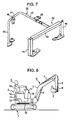
- Fig. 7 is an overall view of the hood support device.
- the hood support frame 38 is provided as a gate-shaped frame member defined by right and left columns 40 and 41 and a lateral beam 42 laid between upper ends of the columns 40 and 41. Lower ends of the columns 40 and 41 are attached to a bottom surface of the upper frame 30 directly or via mounting members in a state in which the hood support frame 38 substantially crosses a front end of the engine room 33.
- the support member 39 is shaped like a rib formed by bending a pipe, a rod, or a mold material (a circular pipe in Fig. 7 ), that is, includes a longitudinal side portion 43 longitudinally traversing the widthwise center of the upper opening of the engine room 33, a lateral side portion 44 horizontally extending from a rear end of the longitudinal side portion 43 to the right via a gently rounded corner, and a rear column 45 vertically extending downward from a leading end of the lateral side portion 44.
- a front end of the longitudinal side portion 43 is connected to a middle portion in the right-left direction of the lateral beam 42 of the hood support frame 38 via connecting fittings 46 and 47, and a lower end of the rear column 45 is attached to the bottom surface of the upper frame 30.
- the hood support device formed by a combination of the hood support frame 38 and the support member 39 is entirely shaped like a letter J inversed in the right-left direction in plan view, and is gate-shaped in side view.
- a front end of the hood 32 is supported by the hood support frame 38 over most of the width of the hood 32.
- hood 32 is supported by the longitudinal side portion 43 of the support member 39 over the substantially entire length in the front-rear direction, and the rear end of the hood 32 is supported by the lateral side portion 44 and the rear column 45.
- the front end of the longitudinal side portion 43 is attached to a hydraulic tank (not shown) via a mounting seat 48.
- mount members are provided on the right and left sides of the longitudinal side portion 43 of the support member 39, and receive a load from above the hood 32 by contact with a lower surface of the hood 32.
- a left mount member is provided, for example, in a fuel tank (not shown) on the rear left side of the engine room 33.
- a hydraulic hose and an electric wire (generically referred to as hoses) 51 are provided between the engine room 33 and the console boxes 36.
- the hoses 51 exchange hydraulic pressure and electric power between hydraulic and electric equipment (not shown) provided in the console boxes 36 (a remote control valve as hydraulic equipment and switches and a monitor panel as electric equipment) and hydraulic and electric equipment provided in the engine room 33 (a control valve 50 as hydraulic equipment and a controller and a battery (not shown) as electric equipment).
- the right and left console boxes 36 turn together with the hood 32, and therefore, the hoses 51 also turn in conjunction with opening and closing of the hood 32.
- the shovel adopts the following structures so that the hoses 51 do not obstruct opening and closing of the hood 32, an undue force does not act on the hoses 51, and a routing structure is not complicated to prevent these problems.
- the right and left columns 40 and 41 of the hood support frame 38 are angular U-shaped in section and are open rearward, as shown in Fig. 6 , and the hoses 51 are routed along the columns 40 and 41.
- hydraulic hoses 51a of the hoses 51 are routed inside and along the columns 40 and 41, and electric wires 51b are routed outside and along the columns 40 and 41.
- the hoses 51 are connected at lower ends to the equipment in the engine room 33 and at upper ends to the console boxes 36.
- the hoses 51 are held by the columns 40 and 41 inside and outside the columns 40 and 41 by, for example, bands (not shown).
- grommets (not shown) are attached to hose takeout openings 52 provided at right and left front ends of the hood 32.
- the hoses 51 are sorted according to the type (hydraulic hoses and electric wire) by the grommets, and are guided to the console boxes 36.
- intermediate portions 51j of the hoses 51 between the engine room 33 and the console boxes 36 are routed along a path such as to pass through or by the axis of the hood shaft 34 in side view and to turn on the hood shaft 34 during opening and closing of the hood 32.
- this routing structure can minimize the amount of stretch and retraction of the hoses 51 (intermediate portions 51j) due to opening and closing of the hood 32, it is unnecessary to add a mechanism (e.g., a hose reel) for absorbing stretch and retraction or a structure for preventing interference between the hoses 51 and the structures due to stretch and retraction. For this reason, the structure for routing the hoses is simplified, and the hoses 51 will not be damaged by an excessive force.
- a mechanism e.g., a hose reel
- hoses 51 are routed along the columns 40 and 41 on both sides of the hood support frame 38 for supporting the front end of the hood 32, they can be easily routed and be protected.
- columns 40 and 41 also function as hose guide members, a special guide member is unnecessary, and this achieves simplification of the structure and cost reduction.
- the hydraulic hoses 51a and the electric wires 51b can be easily and orderly routed, and this provides a maintenance advantage.
- a driver's seat and a console box are juxtaposed on a hood that opens and closes an engine room provided in the rear of an upper frame.
- the driver's seat and the console box turn together with the hood.
Landscapes
- Engineering & Computer Science (AREA)
- Mechanical Engineering (AREA)
- Mining & Mineral Resources (AREA)
- Civil Engineering (AREA)
- General Engineering & Computer Science (AREA)
- Structural Engineering (AREA)
- Transportation (AREA)
- Aviation & Aerospace Engineering (AREA)
- Chemical & Material Sciences (AREA)
- Combustion & Propulsion (AREA)
- Component Parts Of Construction Machinery (AREA)
- Superstructure Of Vehicle (AREA)
Abstract
A driver's seat (35) and a console box (36) are juxtaposed on a hood (32) that opens and closes an engine room provided in the rear of an upper frame (30). The driver's seat (35) and the console box (36) turn together with the hood (32). With this structure, operability of a control lever is improved at the driver's seat (35), a configuration is simplified by adopting only one turn mechanism for the hood (32), maintenance is facilitated by enlarging a maintenance opening, and design flexibility is increased.
Description
- The present invention relates to a construction machine, such as a hydraulic shovel, in which an engine room is covered with a hood and a driver's seat is provided on the hood.
- In a small-sized shovel disclosed in Japanese Unexamined Patent Application Publication No.
2004-137884 body 2 is rotatably mounted on a lower traveling body 1 of a crawler type, and a working attachment 9 is attached to the upper rotatingbody 2, as shown inFigs. 8 and9 . The working attachment 9 includes aboom 3, an arm 4, a bucket 5, and hydraulic cylinders (a boom cylinder, an arm cylinder, and a bucket cylinder) 6 to 8 for driving theboom 3, the arm 4, and the bucket 5. - An
engine room 13 is provided in the rear of anupper frame 10 that constitutes the upper rotatingbody 2, and is surrounded by right and left side panels (only one of the side panels is shown) 11, ahood 12, etc. Theengine room 13 stores equipment including an engine (not shown). - The
hood 12 is L-shaped in side view, and covers an upper side and a rear side of theengine room 13. Thehood 12 is attached to theupper frame 10 in a manner such as to turn on a hood shaft (hinge) 14 provided at a front end thereof in order to open and close upper and rear openings of theengine room 13. -
Fig. 8 illustrates a state in which thehood 12 is closed, andFig. 9 illustrates a state in which thehood 12 is open. In the open state of thehood 12, maintenance of the equipment is performed. - A driver's
seat 15 is provided on thehood 12. An operator O operates acontrol lever 17 of aconsole box 16 provided on a floor in front of the driver'sseat 15 while sitting on the driver'sseat 15. - The
console box 16 stores thecontrol lever 17, a remote control valve (hydraulic equipment) to be operated by thecontrol lever 17, and electric equipment (not shown) such as switches and a monitor panel. - Japanese Unexamined Patent Application Publication No.
2001-107394 - When only the driver's
seat 15 is provided on thehood 12, as in Related Art 1 shown inFigs. 8 and9 , theconsole box 16 needs to be provided at the position on the front floor at a distance from the driver'sseat 15, and this reduces operability of thecontrol lever 17. - In contrast, when the hood and the console box that are juxtaposed are separately turned as in
Related Art 2, there are the following disadvantages: - (I) Since it is necessary to provide two mechanisms for turning the hood and the console box, the structure is complicated and the cost increases.
- (II) The aperture area (maintenance opening) is reduced by the presence of the console box in a state in which the hood is open, and this is disadvantageous in maintenance.
- (III) Since there is a restriction that the driver's seat and the console box should not interfere with each other during their turns, the flexibility in designing the driver's seat and the console box are reduced.
- An object of the present invention is to provide a construction machine that allows a control lever to be operated at a driver's seat with high operability, that simplifies a configuration by adopting only one turn mechanism for a hood, that facilitates maintenance by enlarging a maintenance opening, and that increases design flexibility.
- A construction machine according to an aspect of the present invention includes a lower traveling body; an upper rotating body mounted on the lower traveling body; an engine room provided in the rear of an upper frame of the upper rotating body and having an upper opening and a rear opening; a hood including an upper face portion configured to cover the upper opening and a rear face portion configured to cover the rear opening, the hood turning on a hood shaft at a front end of the upper face portion so as to open and close the upper and rear openings; and a driver's seat and a console box juxtaposed on an upper surface of the upper face portion of the hood in a manner such as to turn together with the hood, the console box having a control lever and hydraulic and electric equipment.
- According to the present invention, since the driver's seat and the console box are juxtaposed on the hood in a manner such as to turn together, operability of the control lever of the console box can be improved.
- Moreover, since only one turn mechanism for the hood will do, the structure is simplified and the cost is reduced.
- In addition, since the maintenance opening can be widely opened by the hood, maintenance is facilitated. Further, since the driver's seat and the console box do not interfere with each other during turning, the flexibility in design can be increased.
-
-
Fig. 1 is an overall side view of a small-sized shovel according to an embodiment of the present invention; -
Fig. 2 is an enlarged and partially cutaway view of a part of an-upper rotating body in the shovel; -
Fig. 3 is a side view illustrating a state in which a hood is opened from a state shown inFig. 2 ; -
Fig. 4 is a perspective view illustrating the state shown inFig. 3 ; -
Fig. 5 is an enlarged partial view of the part shown inFig. 2 ; -
Fig. 6 is an enlarged sectional view taken along line VI-VI inFig. 5 ; -
Fig. 7 is a perspective view of a hood support device; -
Fig. 8 is a schematic side view of a small-sized shovel of the related art; and -
Fig. 9 is a view equivalent toFig. 8 , illustrating a state in which a hood is open. - An embodiment of the present invention will be described with reference to
Figs. 1 to 6 . - In the embodiment, the present invention is applied to a small-sized shovel in correspondence with the description of the related art.
- In the embodiment, the following structures are the same as those adopted in the small-sized shovel of the related art shown in
Figs. 8 and9 : - (i) The small-sized shovel includes a lower traveling
body 21 of a crawler type, an upper rotatingbody 22 rotatably mounted on the lower travelingbody 21, and a workingattachment 29 attached to the upper rotatingbody 22. The workingattachment 29 includes aboom 23, anarm 24, abucket 25, and hydraulic cylinders (a boom cylinder, an arm cylinder, and a bucket cylinder) 26 to 28 for driving theboom 23, thearm 24, and thebucket 25. - (ii) An
engine room 33 is provided in the rear of anupper frame 30 that constitutes the upper rotatingbody 22. Theengine room 33 is surrounded by right and left side panels (only one of them is shown) 31, ahood 32, etc. in a manner such as to have upper and rear openings. Theengine room 33 stores equipment including an engine (not shown). - (iii) As shown in detail in
Figs. 2 to 4 , thehood 32 is L-shaped and includes anupper face portion 32a for covering an upper side of theengine room 33 and arear face portion 32b for covering a rear side of theengine room 33. Thehood 32 is attached to theupper frame 30, and turns on a hood shaft (hinge) 34 at a front end thereof so as to open and close the upper and rear openings of theengine room 33. - In the embodiment, a driver's
seat 35 and right and left console boxes 36 (only one of them is shown) are juxtaposed on the hood 32 (upper face portion 32a), and turn together with thehood 32. - The
console boxes 36 each incorporate acontrol lever 37, a remote control valve (hydraulic equipment) to be operated by thecontrol lever 37, and electric equipment (switches and a monitor panel), and are provided on thehood 32 on the right and left sides of the driver'sseat 35. - Since the
console boxes 36 are provided beside the driver'sseat 35 in this way, operability of thecontrol lever 37 is higher than when they are provided on a floor in front of the driver's seat. - Moreover, since only one turn mechanism for the
hood 32 will do, the structure is simplified and the cost is low. - Further, a maintenance opening (both the upper and rear openings of the engine room 33) can be widely opened by the
hood 32, and this provides a maintenance advantage. - In addition, the problem of interference between the driver's
seat 35 and thehood 32 during turning does not occur, unlike the method for separately turning the driver'sseat 35 and thehood 32, and therefore, the flexibility in design is increased. - As a hood support device for supporting the
hood 32 in a closed state, ahood support frame 38 and asupport member 39 are provided in theengine room 33.Fig. 7 is an overall view of the hood support device. - The
hood support frame 38 is provided as a gate-shaped frame member defined by right andleft columns lateral beam 42 laid between upper ends of thecolumns columns upper frame 30 directly or via mounting members in a state in which thehood support frame 38 substantially crosses a front end of theengine room 33. - The
support member 39 is shaped like a rib formed by bending a pipe, a rod, or a mold material (a circular pipe inFig. 7 ), that is, includes alongitudinal side portion 43 longitudinally traversing the widthwise center of the upper opening of theengine room 33, alateral side portion 44 horizontally extending from a rear end of thelongitudinal side portion 43 to the right via a gently rounded corner, and arear column 45 vertically extending downward from a leading end of thelateral side portion 44. A front end of thelongitudinal side portion 43 is connected to a middle portion in the right-left direction of thelateral beam 42 of thehood support frame 38 via connectingfittings 46 and 47, and a lower end of therear column 45 is attached to the bottom surface of theupper frame 30. - In this way, the hood support device formed by a combination of the
hood support frame 38 and thesupport member 39 is entirely shaped like a letter J inversed in the right-left direction in plan view, and is gate-shaped in side view. A front end of thehood 32 is supported by thehood support frame 38 over most of the width of thehood 32. - Further, almost the widthwise center of the
hood 32 is supported by thelongitudinal side portion 43 of thesupport member 39 over the substantially entire length in the front-rear direction, and the rear end of thehood 32 is supported by thelateral side portion 44 and therear column 45. - To increase the mounting strength of the
support member 39, the front end of thelongitudinal side portion 43 is attached to a hydraulic tank (not shown) via a mountingseat 48. - Further, to increase the hood support strength, mount members are provided on the right and left sides of the
longitudinal side portion 43 of thesupport member 39, and receive a load from above thehood 32 by contact with a lower surface of thehood 32. - While only a
right mount member 49 provided in thelateral side portion 44 of thesupport member 39, of the mount members, is shown in the figures, a left mount member is provided, for example, in a fuel tank (not shown) on the rear left side of theengine room 33. - A hydraulic hose and an electric wire (generically referred to as hoses) 51 are provided between the
engine room 33 and theconsole boxes 36. Thehoses 51 exchange hydraulic pressure and electric power between hydraulic and electric equipment (not shown) provided in the console boxes 36 (a remote control valve as hydraulic equipment and switches and a monitor panel as electric equipment) and hydraulic and electric equipment provided in the engine room 33 (acontrol valve 50 as hydraulic equipment and a controller and a battery (not shown) as electric equipment). - In this shovel of the embodiment, the right and left
console boxes 36 turn together with thehood 32, and therefore, thehoses 51 also turn in conjunction with opening and closing of thehood 32. - Accordingly, the shovel adopts the following structures so that the
hoses 51 do not obstruct opening and closing of thehood 32, an undue force does not act on thehoses 51, and a routing structure is not complicated to prevent these problems. - The right and left
columns hood support frame 38 are angular U-shaped in section and are open rearward, as shown inFig. 6 , and thehoses 51 are routed along thecolumns - More specifically, referring to
Fig. 6 ,hydraulic hoses 51a of thehoses 51 are routed inside and along thecolumns electric wires 51b are routed outside and along thecolumns hoses 51 are connected at lower ends to the equipment in theengine room 33 and at upper ends to theconsole boxes 36. - The
hoses 51 are held by thecolumns columns - Referring to
Fig. 5 , grommets (not shown) are attached tohose takeout openings 52 provided at right and left front ends of thehood 32. Thehoses 51 are sorted according to the type (hydraulic hoses and electric wire) by the grommets, and are guided to theconsole boxes 36. - In this case, as shown in
Fig. 5 (illustration of thesupport member 39 is omitted for easy understanding),intermediate portions 51j of thehoses 51 between theengine room 33 and theconsole boxes 36 are routed along a path such as to pass through or by the axis of thehood shaft 34 in side view and to turn on thehood shaft 34 during opening and closing of thehood 32. - Since this routing structure can minimize the amount of stretch and retraction of the hoses 51 (
intermediate portions 51j) due to opening and closing of thehood 32, it is unnecessary to add a mechanism (e.g., a hose reel) for absorbing stretch and retraction or a structure for preventing interference between thehoses 51 and the structures due to stretch and retraction. For this reason, the structure for routing the hoses is simplified, and thehoses 51 will not be damaged by an excessive force. - In other words, it is possible to solve the problems of the
hoses 51 caused when theconsole boxes 36 and thehood 32 are turned together. - In this case, since the
hoses 51 are routed along thecolumns hood support frame 38 for supporting the front end of thehood 32, they can be easily routed and be protected. - Further, since the
columns - Further, since the
hoses 51 are sorted and guided inside and outside thecolumns hydraulic hoses 51a and theelectric wires 51b can be easily and orderly routed, and this provides a maintenance advantage. - In addition, since the
hydraulic hoses 51a and theelectric wires 51b are separated, interference therebetween (an adverse effect of an electric spark on the hydraulic hoses and heat conduction between thehydraulic hoses 51a and theelectric wires 51b) can be prevented. -
- (1) While the
hoses 51 are separately routed inside and outside the columns according to the type in the above-described embodiment, all of thehoses 51 may be routed inside thecolumns hoses 51 may be provided inside thecolumns - (2) While both the right and left
columns hood support frame 38 also function as the hose guide members in the above-described embodiment, only one of thecolumns
Alternatively, separately from thecolumns columns - (3) While the present invention is suitably applied to the small-sized shovel, it is also applicable to other construction machines having mechanical configurations similar to the configuration of the small-sized shovel.
- Although the invention has been described with reference to the preferred embodiments in the attached figures, it is noted that equivalents may be employed and substitutions may be made herein without departing from the scope of the invention as recited in the claims.
- A driver's seat and a console box are juxtaposed on a hood that opens and closes an engine room provided in the rear of an upper frame. The driver's seat and the console box turn together with the hood. With this structure, operability of a control lever is improved at the driver's seat, a configuration is simplified by adopting only one turn mechanism for the hood, maintenance is facilitated by enlarging a maintenance opening, and design flexibility is increased.
Claims (5)
- A construction machine comprising:a lower traveling body;an upper rotating body mounted on the lower traveling body;an engine room provided in the rear of an upper frame of the upper rotating body, and having an upper opening and a rear opening;a hood including an upper face portion configured to cover the upper opening and a rear face portion configured to cover the rear opening, the hood turning on a hood shaft provided at a front end of the upper face portion so as to open and close the upper opening and the rear opening; anda driver's seat and a console box juxtaposed on an upper surface of the upper face portion of the hood in a manner such as to turn together with the hood, the console box having a control lever and hydraulic and electric equipment.
- The construction machine according to Claim 1, further comprising:hoses configured to exchange hydraulic pressure and electric power between hydraulic and electric equipment provided in the console box and hydraulic and electric equipment provided in the engine room, the hoses including intermediate portions that extend from the engine room to the console box and that are routed along a path such as to turn on the hood shaft near the hood shaft when the hood turns.
- The construction machine according to Claim 2, further comprising:a hose guide member configured to route and guide the hoses and provided in the engine room.
- The construction machine according to Claim 3, further comprising:a hood support frame configured to support a front end of the hood in a state in which the hood is closed, and provided at a front end of the engine room,wherein the hood support frame includes columns having an angular U-shaped cross section and provided on both right and left sides of the hood support frame, and the hoses are routed using at least one of the columns as the hose guide member.
- The construction machine according to Claim 4,
wherein the hoses are separately routed inside and outside the at least one of the columns of the hood support frame according to types of the hoses.
Applications Claiming Priority (1)
| Application Number | Priority Date | Filing Date | Title |
|---|---|---|---|
| JP2009115155A JP5381309B2 (en) | 2009-05-12 | 2009-05-12 | Construction machinery |
Publications (1)
| Publication Number | Publication Date |
|---|---|
| EP2253763A1 true EP2253763A1 (en) | 2010-11-24 |
Family
ID=42562542
Family Applications (1)
| Application Number | Title | Priority Date | Filing Date |
|---|---|---|---|
| EP10162093A Withdrawn EP2253763A1 (en) | 2009-05-12 | 2010-05-06 | Construction machine |
Country Status (3)
| Country | Link |
|---|---|
| EP (1) | EP2253763A1 (en) |
| JP (1) | JP5381309B2 (en) |
| KR (1) | KR20100122452A (en) |
Cited By (2)
| Publication number | Priority date | Publication date | Assignee | Title |
|---|---|---|---|---|
| US20230287652A1 (en) * | 2020-11-27 | 2023-09-14 | Kubota Corporation | Working machine |
| EP4502281A4 (en) * | 2022-03-25 | 2026-04-29 | Hitachi Construction Machinery Tierra Co Ltd | CONSTRUCTION MACHINE |
Families Citing this family (6)
| Publication number | Priority date | Publication date | Assignee | Title |
|---|---|---|---|---|
| JP5850021B2 (en) | 2013-10-30 | 2016-02-03 | コベルコ建機株式会社 | Construction machine routing structure |
| DE102016106647A1 (en) * | 2015-04-17 | 2016-10-20 | Kubota Corporation | Work machine, support mechanism for operating device and shock absorbing mechanism for operating device |
| JP6731898B2 (en) * | 2017-09-14 | 2020-07-29 | ヤンマーパワーテクノロジー株式会社 | Work vehicle |
| JP6894334B2 (en) * | 2017-09-20 | 2021-06-30 | ヤンマーパワーテクノロジー株式会社 | Work vehicle |
| JP6985078B2 (en) * | 2017-09-20 | 2021-12-22 | ヤンマーパワーテクノロジー株式会社 | Work vehicle |
| JP7049039B2 (en) * | 2020-07-01 | 2022-04-06 | ヤンマーパワーテクノロジー株式会社 | Work vehicle |
Citations (4)
| Publication number | Priority date | Publication date | Assignee | Title |
|---|---|---|---|---|
| EP1074665A1 (en) * | 1999-08-03 | 2001-02-07 | Kobelco Construction Machinery Co., Ltd. | Control device for a construction machine |
| JP2002201669A (en) * | 2000-12-28 | 2002-07-19 | Hitachi Constr Mach Co Ltd | Console box device for construction machine |
| EP1783283A1 (en) * | 2004-06-09 | 2007-05-09 | Komatsu Ltd. | Working vehicle |
| EP2168805A2 (en) * | 2008-09-19 | 2010-03-31 | Kobelco Construction Machinery Co., Ltd. | Construction machine |
Family Cites Families (3)
| Publication number | Priority date | Publication date | Assignee | Title |
|---|---|---|---|---|
| JP4200194B2 (en) * | 1999-04-26 | 2008-12-24 | ヤンマー建機株式会社 | Canopy support structure for turning work vehicle |
| CN1798677A (en) * | 2003-02-27 | 2006-07-05 | 株式会社小松制作所 | Rear end small revolving type hydraulic shovel |
| JP4550623B2 (en) * | 2005-02-25 | 2010-09-22 | 日立建機株式会社 | Construction machinery |
-
2009
- 2009-05-12 JP JP2009115155A patent/JP5381309B2/en not_active Expired - Fee Related
-
2010
- 2010-05-06 EP EP10162093A patent/EP2253763A1/en not_active Withdrawn
- 2010-05-11 KR KR1020100043708A patent/KR20100122452A/en not_active Ceased
Patent Citations (4)
| Publication number | Priority date | Publication date | Assignee | Title |
|---|---|---|---|---|
| EP1074665A1 (en) * | 1999-08-03 | 2001-02-07 | Kobelco Construction Machinery Co., Ltd. | Control device for a construction machine |
| JP2002201669A (en) * | 2000-12-28 | 2002-07-19 | Hitachi Constr Mach Co Ltd | Console box device for construction machine |
| EP1783283A1 (en) * | 2004-06-09 | 2007-05-09 | Komatsu Ltd. | Working vehicle |
| EP2168805A2 (en) * | 2008-09-19 | 2010-03-31 | Kobelco Construction Machinery Co., Ltd. | Construction machine |
Cited By (3)
| Publication number | Priority date | Publication date | Assignee | Title |
|---|---|---|---|---|
| US20230287652A1 (en) * | 2020-11-27 | 2023-09-14 | Kubota Corporation | Working machine |
| US12091836B2 (en) * | 2020-11-27 | 2024-09-17 | Kubota Corporation | Working machine with detailed operation device operating working device |
| EP4502281A4 (en) * | 2022-03-25 | 2026-04-29 | Hitachi Construction Machinery Tierra Co Ltd | CONSTRUCTION MACHINE |
Also Published As
| Publication number | Publication date |
|---|---|
| JP2010265582A (en) | 2010-11-25 |
| JP5381309B2 (en) | 2014-01-08 |
| KR20100122452A (en) | 2010-11-22 |
Similar Documents
| Publication | Publication Date | Title |
|---|---|---|
| EP1589153B1 (en) | Swiveling utility machine having swivel deck | |
| US7810597B2 (en) | Battery placement and support on the body frame of a construction machine | |
| US8038202B2 (en) | Operators section construction for work vehicle | |
| KR102178694B1 (en) | Seat stand and working machine having the same | |
| JP5381309B2 (en) | Construction machinery | |
| JP7848070B2 (en) | Construction machinery | |
| EP2868809B1 (en) | Working machine with a console box | |
| JP3443371B2 (en) | Hydraulic piping structure of construction machinery | |
| JP7851129B2 (en) | Front loader | |
| KR20240009871A (en) | Construction machine | |
| JP5282463B2 (en) | Construction machinery | |
| JP4133899B2 (en) | Swivel work machine | |
| JP7694186B2 (en) | electric work machine | |
| JP4619170B2 (en) | Swivel work machine | |
| JP2014031687A (en) | Work machine | |
| EP4534763A1 (en) | Work machine | |
| JP5803982B2 (en) | Work machine | |
| JP3822078B2 (en) | Swivel work machine | |
| JP7049039B2 (en) | Work vehicle | |
| JP7150652B2 (en) | riding lawn mower | |
| JP4404306B2 (en) | Arrangement structure of fuse unit in construction machinery | |
| JP2026053935A (en) | Working machinery | |
| JP2000096612A (en) | Turning machine and cabin used for it | |
| JP4088693B2 (en) | Ultra-small turning machine | |
| JPH11313505A (en) | Hydraulic device for lifting and lowering the tractor work equipment |
Legal Events
| Date | Code | Title | Description |
|---|---|---|---|
| PUAI | Public reference made under article 153(3) epc to a published international application that has entered the european phase |
Free format text: ORIGINAL CODE: 0009012 |
|
| 17P | Request for examination filed |
Effective date: 20100506 |
|
| AK | Designated contracting states |
Kind code of ref document: A1 Designated state(s): AL AT BE BG CH CY CZ DE DK EE ES FI FR GB GR HR HU IE IS IT LI LT LU LV MC MK MT NL NO PL PT RO SE SI SK SM TR |
|
| AX | Request for extension of the european patent |
Extension state: BA ME RS |
|
| STAA | Information on the status of an ep patent application or granted ep patent |
Free format text: STATUS: THE APPLICATION HAS BEEN WITHDRAWN |
|
| 18W | Application withdrawn |
Effective date: 20160502 |