EP2253496A1 - Evaporator assembly for an HVAC system - Google Patents
Evaporator assembly for an HVAC system Download PDFInfo
- Publication number
- EP2253496A1 EP2253496A1 EP10161591A EP10161591A EP2253496A1 EP 2253496 A1 EP2253496 A1 EP 2253496A1 EP 10161591 A EP10161591 A EP 10161591A EP 10161591 A EP10161591 A EP 10161591A EP 2253496 A1 EP2253496 A1 EP 2253496A1
- Authority
- EP
- European Patent Office
- Prior art keywords
- cooler
- sub
- evaporator
- refrigerant
- temperature
- Prior art date
- Legal status (The legal status is an assumption and is not a legal conclusion. Google has not performed a legal analysis and makes no representation as to the accuracy of the status listed.)
- Granted
Links
Images


Classifications
-
- B—PERFORMING OPERATIONS; TRANSPORTING
- B60—VEHICLES IN GENERAL
- B60H—ARRANGEMENTS OF HEATING, COOLING, VENTILATING OR OTHER AIR-TREATING DEVICES SPECIALLY ADAPTED FOR PASSENGER OR GOODS SPACES OF VEHICLES
- B60H1/00—Heating, cooling or ventilating devices
- B60H1/32—Cooling devices
- B60H1/3204—Cooling devices using compression
- B60H1/3227—Cooling devices using compression characterised by the arrangement or the type of heat exchanger, e.g. condenser, evaporator
-
- B—PERFORMING OPERATIONS; TRANSPORTING
- B60—VEHICLES IN GENERAL
- B60H—ARRANGEMENTS OF HEATING, COOLING, VENTILATING OR OTHER AIR-TREATING DEVICES SPECIALLY ADAPTED FOR PASSENGER OR GOODS SPACES OF VEHICLES
- B60H1/00—Heating, cooling or ventilating devices
- B60H1/32—Cooling devices
- B60H1/3233—Cooling devices characterised by condensed liquid drainage means
-
- B—PERFORMING OPERATIONS; TRANSPORTING
- B60—VEHICLES IN GENERAL
- B60H—ARRANGEMENTS OF HEATING, COOLING, VENTILATING OR OTHER AIR-TREATING DEVICES SPECIALLY ADAPTED FOR PASSENGER OR GOODS SPACES OF VEHICLES
- B60H1/00—Heating, cooling or ventilating devices
- B60H1/32—Cooling devices
- B60H1/3233—Cooling devices characterised by condensed liquid drainage means
- B60H1/32331—Cooling devices characterised by condensed liquid drainage means comprising means for the use of condensed liquid, e.g. for humidification or for improving condenser performance
Definitions
- the present invention relates to an air conditioning system for a vehicle HVAC system and more specifically to an air conditioning system with an evaporator assembly that includes a sub-cooler.
- FIG. 1 shows a schematic of a typical air conditioning system 100 for an HVAC ( H eating V entilating and A ir C onditioning) system in a vehicle.
- the air conditioning system 100 includes a compressor 102, condenser 104, a sub-cooler 106, a thermal expansion valve (hereinafter "TXV") 108, and an evaporator 110.
- TXV thermal expansion valve
- a refrigerant is cycled through the air conditioning system 100 in the direction indicated by the arrows.
- the refrigerant cycle involves a three-phase process that includes pressurization, condensation and vaporization, which will be subsequently explained.
- the refrigerant is a low pressure, low temperature gas.
- the compressor 102 compresses the low pressure, low temperature gas into a high pressure, high temperature gas. Pressurizing the refrigerant causes the refrigerant to become much hotter than the outside air, which ensures that the refrigerant will change from a gas to a liquid in the next phase.
- the refrigerant is a high pressure, high temperature gas.
- outside air drawn over the condenser 104 absorbs the heat contained in the refrigerant to thereby cause the refrigerant to condense into a high pressure, high temperature liquid.
- the outside air carries the heat that was absorbed in the evaporation phase described below away from the condenser 104.
- the refrigerant is a high pressure, high temperature liquid.
- the sub-cooler 106 at the exit side of the condenser 104 reduces the temperature of the refrigerant for two reasons. The first reason is to make sure that all of the refrigerant has been transformed from a gas to a liquid. The second reason is to allow the refrigerant to vaporize in the evaporator 110 at a lower temperature thereby allowing the evaporator 110 to work more efficiently. It should be noted that the sub-cooler 106 reduces the temperature of the refrigerant by only a small amount, typically in the range of 5-10°C. Thus, at stage 118, after the refrigerant exits the sub-cooler 106, the refrigerant is still considered a high pressure, high temperature liquid.
- the refrigerant Prior to entering the evaporator 110, the refrigerant enters the TXV 108.
- the TXV serves more than one function.
- the TXV 108 regulates the flow of refrigerant into the evaporator 110 based on cooling demand.
- the TXV 108 also reduces the pressure of the refrigerant, which further decreases the temperature of the refrigerant. This allows the refrigerant to vaporize at a lower temperature once in the evaporator 110 to ensure that the refrigerant will absorb the maximum amount of heat.
- the refrigerant is a low pressure, low temperature liquid.
- a blower forces warm air drawn from inside the vehicle over the evaporator 110.
- the refrigerant removes the heat from the warm air, which causes the refrigerant in the evaporator 110 to boil thereby converting the refrigerant from a liquid to a gas.
- the warm air blowing across the evaporator 110 is cooled to a temperature less than a temperature inside the vehicle.
- the cool air exits through air conditioning vents to the inside of the vehicle at a much lower temperature than the air inside the vehicle thereby cooling the interior of the vehicle. Simultaneously, the heated refrigerant exits the evaporator 110 and the cycle is repeated.
- condensation forms on the evaporator because the moisture from the warm air condenses on the cold evaporator.
- the condensation eventually drains to the ground outside the vehicle.
- a disadvantage of the current air conditioning system is that the system loses cooling energy due to the drainage of the condensation that forms on the evaporator.
- the present invention overcomes the above mentioned disadvantages by providing an evaporator assembly for a vehicle air conditioning system that includes a housing, an evaporator, and a sub-cooler.
- the evaporator and sub-cooler are both housed in the housing and the sub-cooler is arranged below the evaporator.
- an air conditioning system for a vehicle that includes a compressor to pressurize a refrigerant cycling through the air conditioning system, a condenser located downstream of and fluidly connected to the compressor to condense the refrigerant, a first sub-cooler located downstream of and fluidly connected to the condenser to reduce a temperature of the refrigerant to a temperature that is less than a temperature of the refrigerant exiting the condenser, a second sub-cooler located downstream of and fluidly connected to the first sub-cooler, a metering device located downstream of and fluidly connected to the second sub-cooler to reduce a pressure of the refrigerant, and an evaporator located downstream of and fluidly connected to the metering device to convert the refrigerant from a liquid to a gas, the evaporator being located upstream of and fluidly connected to the compressor.
- the second sub-cooler is arranged below the evaporator such that water condensation formed on the evaporator drains onto the second sub-cooler to cool the second sub-cooler such that a temperature of the refrigerant exiting the second sub-cooler is less than a temperature of the refrigerant exiting the first sub-cooler.
- the invention may take physical form in certain parts and arrangement of parts, a preferred embodiment of which will be described in detail in this specification and illustrated in the accompanying drawings that form a part of the specification.
- FIG. 1 is a schematic of a prior air conditioning system for a vehicle.
- FIG. 2 is a schematic of an air conditioning system for a vehicle according to one exemplary embodiment of the present invention.
- FIG. 3 is a perspective view of an evaporator assembly according to an exemplary embodiment of the present invention.
- FIG. 4 is a side view of the evaporator assembly of FIG. 3 .
- FIG. 5 is an enlarged view of the evaporator assembly of FIG. 4 .
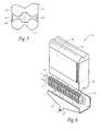
- FIG. 6 is an exploded-perspective view of an evaporator assembly according to a second exemplary embodiment of the present invention.
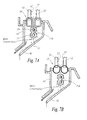
- FIG. 7A is an enlarged view of the evaporator assembly of FIG. 6 showing an extruded evaporator tank.
- FIG. 7B is an enlarged view of the evaporator assembly FIG. 6 showing a stamped evaporator tank.
- FIG. 1 shows a schematic of an air conditioning system 10 for a vehicle HVAC system in accordance with the present invention.
- the air conditioning system 10 includes a compressor 12, condenser 14, a first sub-cooler 16, a metering device 18, and an evaporator assembly 19, shown in FIG. 3 , which includes an evaporator 20 and a second sub-cooler 21.
- the metering device may be any type of metering device commonly known in the art such as, but not limited to, a thermal expansion valve (hereinafter "TXV") or an orifice tube.
- TXV thermal expansion valve
- a refrigerant is cycled through the air conditioning system 10 in the direction indicated by the arrows.
- the refrigerant cycle involves a three-phase process that includes pressurization, condensation and vaporization, which will be subsequently explained.
- the refrigerant is a low pressure, low temperature gas.
- the compressor 12 compresses the refrigerant into a high pressure, high temperature gas. Pressurizing the refrigerant causes the refrigerant to become much hotter than the outside air, which ensures that the refrigerant will change from a gas to a liquid in the condensation phase.
- the refrigerant is a high pressure, high temperature gas.
- outside air drawn over the condenser 14 absorbs the heat contained in the refrigerant to thereby cause the refrigerant to condense into a high pressure, high temperature liquid.
- the outside air carries the heat that was absorbed in the evaporation phase described below away from the condenser 14.
- the refrigerant is a high pressure, high temperature liquid.
- the first sub-cooler 16 at the exit side of the condenser 14 reduces the temperature of the refrigerant for at least two reasons. A first reason is to make sure that all of the refrigerant has been transformed from a gas to a liquid. The second reason is to allow the refrigerant to vaporize in the evaporator 20 at a lower temperature thereby allowing the evaporator 20 to work more efficiently. It should be noted that the first sub-cooler 16 reduces the temperature of the refrigerant by only a small amount, typically in the range of 5-10°C. Thus, at stage 28 the refrigerant is still considered a high pressure, high temperature liquid.
- the refrigerant then enters the second sub-cooler 21.
- the second sub-cooler 21 further reduces the temperature of the refrigerant to further increase the efficiency of the evaporator 20 during the vaporization phase explained below.
- the advantage to the second sub-cooler 21 is that the evaporator 20 and the second sub-cooler are arranged such that the condensation from the evaporator 20 drains onto the second sub-cooler 21 before exiting the vehicle.
- the condensation works as an additional means to cool the second sub-cooler 21, explained further below. Therefore, some of the energy lost in the drainage of the condensation in the typical air conditioning system 100 is recaptured and used to cool the second sub-cooler 21.
- the second sub-cooler 21 reduces the temperature of the refrigerant by a small amount.
- the refrigerant is still considered a high pressure, high temperature liquid.
- the temperature reduction is enough to allow the evaporator 20 to work less and therefore, more efficiently.
- the refrigerant Prior to entering the evaporator 20, the refrigerant enters the TXV 18.
- the TXV 18 serves more than one function.
- the TXV 18 regulates the flow of refrigerant into the evaporator 20 based on cooling demand.
- the TXV 18 also reduces the pressure of the refrigerant, which further decreases the temperature of the refrigerant. This allows the refrigerant to vaporize at a lower temperature once in the evaporator 20 to ensure that the refrigerant will absorb the maximum amount of heat.
- the refrigerant is a low pressure, low temperature liquid.
- a blower forces warm air drawn from inside the vehicle over the evaporator 20.
- the refrigerant removes the heat from the warm air, which causes the refrigerant in the evaporator 20 to boil thereby converting the refrigerant from a liquid to a gas.
- the warm air blowing across the evaporator 20 is cooled to a temperature less than a temperature inside the vehicle.
- the cool air exits through air conditioning vents to the inside of the vehicle at a much lower temperature than the air inside the vehicle thereby cooling the interior of the vehicle. Simultaneously, the heated refrigerant exits the evaporator 20 and the cycle is repeated.
- the evaporator 20 also functions as a dehumidifier and the cool air entering the inside of the vehicle is also dehumidified.
- FIGS. 3-5 show a first embodiment of the evaporator assembly 19 that includes the evaporator 20 and the sub-cooler 21, which serves as the second sub-cooler 21 mentioned above.
- the second sub-cooler 21 will simply be referred to as the sub-cooler 21.
- the evaporator 20 and sub-cooler 21 are arranged in a single evaporator housing 34.
- the sub-cooler 21 is arranged below the evaporator 20 such that the water condensation forming on an outside surface 36 of the evaporator 20 runs down the outside surface 36 of the evaporator 20 over an outside surface 38 (see FIG. 4 ) of the sub-cooler 21.
- the water condensation then drains into a drain pan 40 and out an exit drain 42 where it exits the vehicle.
- the water condensation serves to reduce the temperature of the sub-cooler 21.
- the sub-cooler 21 is preferably a plate/fin type heat exchanger. It should be noted, however, that a tube type heat exchanger with an incoming refrigerant line and an outgoing refrigerant may also be used.
- the evaporator assembly 19 further includes a heat resistant-insulating material 44 situated between the evaporator 20 and the sub-cooler 21, best shown in FIG. 5 .
- the heat resistant-insulating material 44 minimizes the amount of heat dissipated by the sub-cooler 21 from rising upward to the evaporator 20, which would compromise the efficiency of the evaporator 20.
- a gap 46 between each side 48 of the heat resistant-insulating material 44 and each side wall 35 of the housing 34 is minimized to further minimize the amount of heat dissipated by the sub-cooler 21 from rising upward to the evaporator 20.
- FIGS. 6 , 7A, and 7B show two variations of a second embodiment of the evaporator assembly 19.
- the evaporator assembly 19 includes the evaporator 20, the sub-cooler 21 A, and the housing 34.
- the evaporator 20 and sub-cooler 21 A are not housed in the same housing 34. Rather, the sub-cooler 21 A is located outside the housing 34 but still positioned beneath the evaporator 20.
- the water condensation from the evaporator 20 still drains down the outside surface 36 of the housing 34 and onto the sub-cooler 21 A to cool the sub-cooler 21 A in the same fashion as described above.
- the second variation is similar to the first variation except that the second variation does not include the housing 34.
- the evaporator assembly 19 includes the evaporator 20 and the sub-cooler 21 A.
- the warm air from the blower mentioned above, blows across exposed evaporator tubes 50.
- Water condensation forms on an inner surface 52 of each evaporator tube 50 and drains between evaporator tanks 54, 56 and onto the sub-cooler 21 A to cool the sub-cooler 21 A.
- the sub-cooler 21 A includes an incoming refrigerant tube 37 and an outgoing refrigerant tube 39.
- the incoming refrigerant tube 37 and outgoing refrigerant tube 39 of the sub-cooler 21 A are oriented such that a line 41, shown only in FIG. 7A , defined between a center of the both tubes 37, 39 is substantially vertical. It should be noted, however, that the sub-cooler 21 A can be oriented such that the line 41 between the center of each tube is substantially horizontal.
- FIGS. 7A and 7B also show two types of evaporator tanks, which hold the refrigerant that may be used in the present invention. Specifically, FIG. 7A shows an extruded type tank 54 and FIG. 7B shows a stamped type tank 56. It should be noted, however, that other variations of evaporators commonly known in the art may be used in the present invention.
- the present invention introduces a second sub-cooler 21, 21 A into an air conditioning system for a vehicle HVAC system.
- the addition of the second sub-cooler 21, 21 A assists in reducing the temperature of the refrigerant so that the evaporator 20 operates more efficiently.
Landscapes
- Physics & Mathematics (AREA)
- Thermal Sciences (AREA)
- Engineering & Computer Science (AREA)
- Mechanical Engineering (AREA)
- Air-Conditioning For Vehicles (AREA)
Abstract
Description
- The present invention relates to an air conditioning system for a vehicle HVAC system and more specifically to an air conditioning system with an evaporator assembly that includes a sub-cooler.
-
FIG. 1 shows a schematic of a typicalair conditioning system 100 for an HVAC (Heating Ventilating and Air Conditioning) system in a vehicle. Theair conditioning system 100 includes acompressor 102,condenser 104, asub-cooler 106, a thermal expansion valve (hereinafter "TXV") 108, and anevaporator 110. A refrigerant is cycled through theair conditioning system 100 in the direction indicated by the arrows. The refrigerant cycle involves a three-phase process that includes pressurization, condensation and vaporization, which will be subsequently explained. - At
stage 112, before the refrigerant enters thecompressor 102, the refrigerant is a low pressure, low temperature gas. In the pressurization phase, thecompressor 102 compresses the low pressure, low temperature gas into a high pressure, high temperature gas. Pressurizing the refrigerant causes the refrigerant to become much hotter than the outside air, which ensures that the refrigerant will change from a gas to a liquid in the next phase. - At
stage 114, before the refrigerant enters thecondenser 104, the refrigerant is a high pressure, high temperature gas. In the condensation phase, outside air drawn over thecondenser 104 absorbs the heat contained in the refrigerant to thereby cause the refrigerant to condense into a high pressure, high temperature liquid. The outside air carries the heat that was absorbed in the evaporation phase described below away from thecondenser 104. - At
stage 116, before the refrigerant enters thesub-cooler 106, the refrigerant is a high pressure, high temperature liquid. Thesub-cooler 106 at the exit side of thecondenser 104 reduces the temperature of the refrigerant for two reasons. The first reason is to make sure that all of the refrigerant has been transformed from a gas to a liquid. The second reason is to allow the refrigerant to vaporize in theevaporator 110 at a lower temperature thereby allowing theevaporator 110 to work more efficiently. It should be noted that thesub-cooler 106 reduces the temperature of the refrigerant by only a small amount, typically in the range of 5-10°C. Thus, atstage 118, after the refrigerant exits thesub-cooler 106, the refrigerant is still considered a high pressure, high temperature liquid. - Prior to entering the
evaporator 110, the refrigerant enters theTXV 108. The TXV serves more than one function. The TXV 108 regulates the flow of refrigerant into theevaporator 110 based on cooling demand. TheTXV 108 also reduces the pressure of the refrigerant, which further decreases the temperature of the refrigerant. This allows the refrigerant to vaporize at a lower temperature once in theevaporator 110 to ensure that the refrigerant will absorb the maximum amount of heat. Thus, atstage 120, the refrigerant is a low pressure, low temperature liquid. - In the vaporization phase, a blower (not shown) forces warm air drawn from inside the vehicle over the
evaporator 110. The refrigerant removes the heat from the warm air, which causes the refrigerant in theevaporator 110 to boil thereby converting the refrigerant from a liquid to a gas. Thus, the warm air blowing across theevaporator 110 is cooled to a temperature less than a temperature inside the vehicle. The cool air exits through air conditioning vents to the inside of the vehicle at a much lower temperature than the air inside the vehicle thereby cooling the interior of the vehicle. Simultaneously, the heated refrigerant exits theevaporator 110 and the cycle is repeated. - During the vaporization phase, condensation forms on the evaporator because the moisture from the warm air condenses on the cold evaporator. The condensation eventually drains to the ground outside the vehicle. Thus, a disadvantage of the current air conditioning system is that the system loses cooling energy due to the drainage of the condensation that forms on the evaporator.
- Therefore, what is required is an air conditioning system that utilizes the lost energy to increase the efficiency of the air conditioning system.
- In accordance with one aspect, the present invention overcomes the above mentioned disadvantages by providing an evaporator assembly for a vehicle air conditioning system that includes a housing, an evaporator, and a sub-cooler. The evaporator and sub-cooler are both housed in the housing and the sub-cooler is arranged below the evaporator.
- In accordance with another aspect, the present invention overcomes the above mentioned disadvantages by providing an air conditioning system for a vehicle that includes a compressor to pressurize a refrigerant cycling through the air conditioning system, a condenser located downstream of and fluidly connected to the compressor to condense the refrigerant, a first sub-cooler located downstream of and fluidly connected to the condenser to reduce a temperature of the refrigerant to a temperature that is less than a temperature of the refrigerant exiting the condenser, a second sub-cooler located downstream of and fluidly connected to the first sub-cooler, a metering device located downstream of and fluidly connected to the second sub-cooler to reduce a pressure of the refrigerant, and an evaporator located downstream of and fluidly connected to the metering device to convert the refrigerant from a liquid to a gas, the evaporator being located upstream of and fluidly connected to the compressor. The second sub-cooler is arranged below the evaporator such that water condensation formed on the evaporator drains onto the second sub-cooler to cool the second sub-cooler such that a temperature of the refrigerant exiting the second sub-cooler is less than a temperature of the refrigerant exiting the first sub-cooler.
- Additional benefits and advantages of the present invention will become apparent to those skilled in the art to which it pertains upon a reading and understanding of the following detailed specification.
- The invention may take physical form in certain parts and arrangement of parts, a preferred embodiment of which will be described in detail in this specification and illustrated in the accompanying drawings that form a part of the specification.
-
FIG. 1 is a schematic of a prior air conditioning system for a vehicle. -
FIG. 2 is a schematic of an air conditioning system for a vehicle according to one exemplary embodiment of the present invention. -
FIG. 3 is a perspective view of an evaporator assembly according to an exemplary embodiment of the present invention. -
FIG. 4 is a side view of the evaporator assembly ofFIG. 3 . -
FIG. 5 is an enlarged view of the evaporator assembly ofFIG. 4 . -
FIG. 6 is an exploded-perspective view of an evaporator assembly according to a second exemplary embodiment of the present invention. -
FIG. 7A is an enlarged view of the evaporator assembly ofFIG. 6 showing an extruded evaporator tank. -
FIG. 7B is an enlarged view of the evaporator assemblyFIG. 6 showing a stamped evaporator tank. - Prior to describing the evaporator assembly, an air conditioning system containing the inventive evaporator assembly will be described.
-
FIG. 1 shows a schematic of anair conditioning system 10 for a vehicle HVAC system in accordance with the present invention. Theair conditioning system 10 includes acompressor 12,condenser 14, afirst sub-cooler 16, ametering device 18, and anevaporator assembly 19, shown inFIG. 3 , which includes anevaporator 20 and asecond sub-cooler 21. The metering device may be any type of metering device commonly known in the art such as, but not limited to, a thermal expansion valve (hereinafter "TXV") or an orifice tube. For illustration purposes only, a TXV will be used in the embodiment described below and shown in the figures. A refrigerant is cycled through theair conditioning system 10 in the direction indicated by the arrows. The refrigerant cycle involves a three-phase process that includes pressurization, condensation and vaporization, which will be subsequently explained. - At
stage 22, before the refrigerant enters thecompressor 12, the refrigerant is a low pressure, low temperature gas. In the pressurization phase, thecompressor 12 compresses the refrigerant into a high pressure, high temperature gas. Pressurizing the refrigerant causes the refrigerant to become much hotter than the outside air, which ensures that the refrigerant will change from a gas to a liquid in the condensation phase. - At
stage 24, before the refrigerant enters thecondenser 14, the refrigerant is a high pressure, high temperature gas. In the condensation phase, outside air drawn over thecondenser 14 absorbs the heat contained in the refrigerant to thereby cause the refrigerant to condense into a high pressure, high temperature liquid. The outside air carries the heat that was absorbed in the evaporation phase described below away from thecondenser 14. - At
stage 26, before the refrigerant enters thefirst sub-cooler 16, the refrigerant is a high pressure, high temperature liquid. Thefirst sub-cooler 16 at the exit side of thecondenser 14 reduces the temperature of the refrigerant for at least two reasons. A first reason is to make sure that all of the refrigerant has been transformed from a gas to a liquid. The second reason is to allow the refrigerant to vaporize in theevaporator 20 at a lower temperature thereby allowing theevaporator 20 to work more efficiently. It should be noted that thefirst sub-cooler 16 reduces the temperature of the refrigerant by only a small amount, typically in the range of 5-10°C. Thus, atstage 28 the refrigerant is still considered a high pressure, high temperature liquid. - The refrigerant then enters the
second sub-cooler 21. Thesecond sub-cooler 21 further reduces the temperature of the refrigerant to further increase the efficiency of theevaporator 20 during the vaporization phase explained below. The advantage to thesecond sub-cooler 21 is that theevaporator 20 and the second sub-cooler are arranged such that the condensation from theevaporator 20 drains onto thesecond sub-cooler 21 before exiting the vehicle. Thus, the condensation works as an additional means to cool thesecond sub-cooler 21, explained further below. Therefore, some of the energy lost in the drainage of the condensation in the typicalair conditioning system 100 is recaptured and used to cool thesecond sub-cooler 21. - It should further be noted that the
second sub-cooler 21 reduces the temperature of the refrigerant by a small amount. Thus, atstage 30 the refrigerant is still considered a high pressure, high temperature liquid. However, even though thesecond sub-cooler 21 reduces the temperature of the refrigerant by a small amount, the temperature reduction is enough to allow theevaporator 20 to work less and therefore, more efficiently. - Prior to entering the
evaporator 20, the refrigerant enters theTXV 18. TheTXV 18 serves more than one function. TheTXV 18 regulates the flow of refrigerant into theevaporator 20 based on cooling demand. TheTXV 18 also reduces the pressure of the refrigerant, which further decreases the temperature of the refrigerant. This allows the refrigerant to vaporize at a lower temperature once in theevaporator 20 to ensure that the refrigerant will absorb the maximum amount of heat. Thus, atstage 32, the refrigerant is a low pressure, low temperature liquid. - In the vaporization phase, a blower (not shown) forces warm air drawn from inside the vehicle over the
evaporator 20. The refrigerant removes the heat from the warm air, which causes the refrigerant in theevaporator 20 to boil thereby converting the refrigerant from a liquid to a gas. Thus, the warm air blowing across theevaporator 20 is cooled to a temperature less than a temperature inside the vehicle. The cool air exits through air conditioning vents to the inside of the vehicle at a much lower temperature than the air inside the vehicle thereby cooling the interior of the vehicle. Simultaneously, the heated refrigerant exits theevaporator 20 and the cycle is repeated. - Further, during the evaporation phase, condensation forms on the
evaporator 20 because the moisture from the warm air comes in contact with the cold evaporator thereby condensing on theevaporator 20. Thus, theevaporator 20 also functions as a dehumidifier and the cool air entering the inside of the vehicle is also dehumidified. - Referring to
FIGS. 3-5 , theinventive evaporator assembly 19 will now be described.FIGS. 3-5 show a first embodiment of theevaporator assembly 19 that includes theevaporator 20 and the sub-cooler 21, which serves as thesecond sub-cooler 21 mentioned above. Thus, in describing theevaporator assembly 19 thesecond sub-cooler 21 will simply be referred to as the sub-cooler 21. - In the first embodiment, the
evaporator 20 andsub-cooler 21 are arranged in asingle evaporator housing 34. The sub-cooler 21 is arranged below theevaporator 20 such that the water condensation forming on anoutside surface 36 of the evaporator 20 runs down theoutside surface 36 of theevaporator 20 over an outside surface 38 (seeFIG. 4 ) of the sub-cooler 21. The water condensation then drains into adrain pan 40 and out anexit drain 42 where it exits the vehicle. Thus, as explained above, the water condensation serves to reduce the temperature of the sub-cooler 21. - In the first embodiment, the sub-cooler 21 is preferably a plate/fin type heat exchanger. It should be noted, however, that a tube type heat exchanger with an incoming refrigerant line and an outgoing refrigerant may also be used.
- The
evaporator assembly 19 further includes a heat resistant-insulatingmaterial 44 situated between the evaporator 20 and the sub-cooler 21, best shown inFIG. 5 . The heat resistant-insulatingmaterial 44 minimizes the amount of heat dissipated by the sub-cooler 21 from rising upward to theevaporator 20, which would compromise the efficiency of theevaporator 20. In addition, agap 46 between eachside 48 of the heat resistant-insulatingmaterial 44 and eachside wall 35 of thehousing 34 is minimized to further minimize the amount of heat dissipated by the sub-cooler 21 from rising upward to theevaporator 20. -
FIGS. 6 ,7A, and 7B show two variations of a second embodiment of theevaporator assembly 19. Referring toFIG. 6 , in the first variation theevaporator assembly 19 includes theevaporator 20, the sub-cooler 21 A, and thehousing 34. Theevaporator 20 andsub-cooler 21 A, however, are not housed in thesame housing 34. Rather, the sub-cooler 21 A is located outside thehousing 34 but still positioned beneath theevaporator 20. The water condensation from theevaporator 20 still drains down theoutside surface 36 of thehousing 34 and onto the sub-cooler 21 A to cool the sub-cooler 21 A in the same fashion as described above. - Referring to
FIGS. 7A and 7B , the second variation is similar to the first variation except that the second variation does not include thehousing 34. Thus, theevaporator assembly 19 includes theevaporator 20 and the sub-cooler 21 A. In this variation, the warm air from the blower, mentioned above, blows across exposedevaporator tubes 50. Water condensation forms on aninner surface 52 of eachevaporator tube 50 and drains betweenevaporator tanks - In each variation of the second embodiment, the sub-cooler 21 A includes an incoming
refrigerant tube 37 and an outgoingrefrigerant tube 39. Preferably, the incomingrefrigerant tube 37 and outgoingrefrigerant tube 39 of the sub-cooler 21 A are oriented such that aline 41, shown only inFIG. 7A , defined between a center of the bothtubes line 41 between the center of each tube is substantially horizontal. -
FIGS. 7A and 7B also show two types of evaporator tanks, which hold the refrigerant that may be used in the present invention. Specifically,FIG. 7A shows anextruded type tank 54 andFIG. 7B shows a stampedtype tank 56. It should be noted, however, that other variations of evaporators commonly known in the art may be used in the present invention. - In summary, the present invention introduces a
second sub-cooler second sub-cooler evaporator 20 operates more efficiently. - While specific embodiments of the invention have been described and illustrated, it is to be understood that these embodiments are provided by way of example only and that the invention is not to be construed as being limited but only by proper scope of the following claims.
Claims (15)
- An evaporator assembly for a vehicle air conditioning system comprising:an evaporator (20); anda sub-cooler (21) arranged below the evaporator.
- An evaporator assembly of claim 1 further comprising a housing (34) enclosing the evaporator (20) and the sub-cooler (21).
- The evaporator assembly of claim 2 further comprising a heat resistant-insulating material arranged between the evaporator (20) and the sub-cooler (21) to reduce heat dissipated by the sub-cooler (21) from rising upward toward the evaporator (20).
- The evaporator assembly of claim 3 wherein the evaporator includes evaporator tubes (50) and wherein water condensation forms on an inner surface of the evaporator tubes (50) and drains downward onto the sub-cooler (21).
- An air conditioning system for a vehicle comprising:a compressor (12) to pressurize a refrigerant cycling through the air conditioning system (10);a condenser (14) located downstream of and fluidly connected to the compressor (12) to condense the refrigerant;a first sub-cooler (16) located downstream of and fluidly connected to the condenser (14) to reduce a temperature of the refrigerant to a temperature that is less than a temperature of the refrigerant exiting the condenser (14);a second sub-cooler (21) located downstream of and fluidly connected to the first sub-cooler (16);a metering device (18) located downstream of and fluidly connected to the second sub-cooler (21) to reduce a pressure of the refrigerant; andan evaporator (20) located downstream of and fluidly connected to the metering device (18) to convert the refrigerant from a liquid to a gas, the evaporator (20) being located upstream of and fluidly connected to the compressor (12),wherein the second sub-cooler (21) is arranged below the evaporator (20) such that water condensation formed on the evaporator (20) drains onto the second sub-cooler (21) to cool the second sub-cooler (21) such that a temperature of the refrigerant exiting the second sub-cooler is less than a temperature of the refrigerant exiting the first sub-cooler (16).
- The air conditioning system of claim 5, wherein the evaporator and the second sub-cooler (21) are housed in a single housing (34).
- The air conditioning system of claim 6, wherein the evaporator (20) and second sub-cooler (21) are separated by a heat resistant-insulating material to reduce heat dissipated by the second sub-cooler (21) from rising upward toward the evaporator (20) and wherein a gap formed between each side of the heat resistant-insulating material and each side wall of the housing (34) is minimized to reduce the heat dissipated by the second sub-cooler (21) from rising upward toward the evaporator (20).
- The air conditioning system of claim 7, wherein the metering device (18) is a thermal expansion valve, which regulates a flow of refrigerant to the evaporator (20) based on cooling demand.
- The air conditioning system of claim 5, wherein the evaporator (20) is housed in a housing (34) and the second sub-cooler (21) is arranged below the housing (34).
- The air conditioning system of claim 9, wherein the second sub-cooler (21) includes an incoming refrigerant tube (37) and an outgoing refrigerant tube (39), wherein the incoming refrigerant tube (37) and outgoing refrigerant tube (39) are oriented such that a line defined between a center of the incoming refrigerant tube (37) and the outgoing refrigerant tube (39) is substantially vertical.
- The air conditioning system of claim 10, wherein the metering device (18) is a thermal expansion valve, which regulates a flow of refrigerant to the evaporator (20) based on cooling demand.
- An HVAC system for a vehicle comprising:an air conditioner system (10) including:a compressor (12) to pressurize a refrigerant cycling through the air conditioning system (10);a condenser (14) located downstream of and fluidly connected to the compressor (12) to condense the refrigerant;a first sub-cooler (16) located downstream of and fluidly connected to the condenser (14) to reduce a temperature of the refrigerant to a temperature that is less than a temperature of the refrigerant exiting the condenser (14);a second sub-cooler (21) located downstream of and fluidly connected to the first sub-cooler (16);a metering device (18) located downstream of and fluidly connected to the second sub-cooler (21) to reduce a pressure of the refrigerant; andan evaporator (20) located downstream of and fluidly connected to the metering device (18) to convert the refrigerant from a liquid to a gas, the evaporator (20) being located upstream of and fluidly connected to the compressor (12),wherein the second sub-cooler (21) is arranged below the evaporator (20) such that water condensation formed on the evaporator (20) drains onto the second sub-cooler (21) to cool the second sub-cooler (21) such that a temperature of the refrigerant exiting the second sub-cooler (21) is less than a temperature of the refrigerant exiting the first sub-cooler (16).
- The HVAC system of claim 12, wherein the evaporator (20) and the second sub-cooler (21) are housed in a single housing (34), wherein the evaporator (20) and second sub-cooler (21) are separated by a heat resistant-insulating material to reduce heat dissipated by the second sub-cooler (21) from rising upward toward the evaporator (20), and wherein a gap formed between each side of the heat resistant-insulating material and each side wall of the housing (34) is minimized to reduce the heat dissipated by the second sub-cooler (21) from rising upward toward the evaporator (20).
- The HVAC system of claim 13, wherein the metering device (18) is a thermal expansion valve, which regulates a flow of refrigerant to the evaporator (20) based on cooling demand.
- The HVAC system of claim 12, wherein the evaporator (20) is housed in a housing (34) and the second sub-cooler (21) is arranged below the housing (20).
Applications Claiming Priority (1)
| Application Number | Priority Date | Filing Date | Title |
|---|---|---|---|
| US12/437,871 US8561420B2 (en) | 2009-05-08 | 2009-05-08 | Evaporator assembly for an HVAC system |
Publications (2)
| Publication Number | Publication Date |
|---|---|
| EP2253496A1 true EP2253496A1 (en) | 2010-11-24 |
| EP2253496B1 EP2253496B1 (en) | 2011-12-28 |
Family
ID=42931935
Family Applications (1)
| Application Number | Title | Priority Date | Filing Date |
|---|---|---|---|
| EP10161591A Not-in-force EP2253496B1 (en) | 2009-05-08 | 2010-04-30 | Evaporator assembly for an HVAC system |
Country Status (4)
| Country | Link |
|---|---|
| US (1) | US8561420B2 (en) |
| EP (1) | EP2253496B1 (en) |
| JP (1) | JP5620710B2 (en) |
| AT (1) | ATE538958T1 (en) |
Cited By (2)
| Publication number | Priority date | Publication date | Assignee | Title |
|---|---|---|---|---|
| CN104990310A (en) * | 2015-07-02 | 2015-10-21 | 浙江德诚制冷设备成套有限公司 | Evaporator refrigeration device |
| CN106369882A (en) * | 2016-08-25 | 2017-02-01 | 安徽江淮松芝空调有限公司 | Double-layer heat insulation structure of evaporator |
Families Citing this family (13)
| Publication number | Priority date | Publication date | Assignee | Title |
|---|---|---|---|---|
| JP5915761B2 (en) * | 2012-09-21 | 2016-05-11 | 日産自動車株式会社 | Air conditioner for vehicles |
| US9879888B2 (en) * | 2012-10-30 | 2018-01-30 | Lennox Industries Inc. | Auxiliary heat exchanger having fluid retention member for evaporative cooling |
| US20150033771A1 (en) * | 2013-08-02 | 2015-02-05 | Emerald Environmental Technologies | Modular refrigeration and heat reclamation chiller |
| EP3109572B1 (en) * | 2015-06-22 | 2019-05-01 | Lg Electronics Inc. | Refrigerator |
| WO2017106849A1 (en) * | 2015-12-18 | 2017-06-22 | Ricotta Gesualdo | Evaporator and methods of using same |
| CN106274376A (en) * | 2016-08-25 | 2017-01-04 | 安徽江淮松芝空调有限公司 | Air conditioning for automobiles top vaporizer |
| CN110462324B (en) | 2017-03-27 | 2021-07-20 | 大金工业株式会社 | Heat Exchangers and Freezers |
| DE102017205744B4 (en) * | 2017-04-04 | 2025-05-08 | Hanon Systems | Device for distributing the coolant in an air conditioning system of a motor vehicle |
| JP6885308B2 (en) * | 2017-11-20 | 2021-06-09 | トヨタ自動車株式会社 | Vehicle temperature control system |
| US10723204B2 (en) * | 2018-01-26 | 2020-07-28 | Denso International America, Inc. | Vehicular air conditioning system |
| US10605503B2 (en) | 2018-03-29 | 2020-03-31 | Denso International America, Inc. | Condensate enhanced subcooler |
| CN115447339A (en) * | 2022-08-31 | 2022-12-09 | 青岛海尔空调器有限总公司 | Air duct assembly for vehicle-mounted air conditioner and vehicle-mounted air conditioner |
| US20250388062A1 (en) * | 2024-06-20 | 2025-12-25 | Andrew Page | RV AC-Unit Condensation Collection Device |
Citations (3)
| Publication number | Priority date | Publication date | Assignee | Title |
|---|---|---|---|---|
| DE19630431A1 (en) * | 1996-07-27 | 1998-01-29 | Behr Gmbh & Co | Air-conditioning system for motor vehicles |
| EP1422085A1 (en) * | 2002-11-19 | 2004-05-26 | Delphi Technologies, Inc. | Dual evaporator air conditioning system and method of use |
| DE102004012871A1 (en) * | 2004-03-16 | 2005-10-06 | Volkswagen Ag | Air conditioner unit for passenger cabin of vehicle, comprising receptacle and distribution system for condensate |
Family Cites Families (21)
| Publication number | Priority date | Publication date | Assignee | Title |
|---|---|---|---|---|
| US4005949A (en) * | 1974-10-10 | 1977-02-01 | Vilter Manufacturing Corporation | Variable capacity rotary screw compressor |
| ES461192A1 (en) * | 1976-07-29 | 1978-12-01 | Matsushita Electric Industrial Co Ltd | A HEAT PUMP. |
| JPS57134567U (en) * | 1981-02-16 | 1982-08-21 | ||
| JPS59163872U (en) * | 1983-04-20 | 1984-11-02 | 三菱重工業株式会社 | Refrigeration equipment |
| JPH071128B2 (en) * | 1987-02-27 | 1995-01-11 | 株式会社東芝 | Refrigeration cycle for refrigerator |
| US4938035A (en) * | 1987-10-20 | 1990-07-03 | Khanh Dinh | Regenerative fresh-air air conditioning system and method |
| US5109676A (en) * | 1990-07-10 | 1992-05-05 | Sundstrand Corporation | Vapor cycle system evaporator control |
| US5163304A (en) * | 1991-07-12 | 1992-11-17 | Gary Phillippe | Refrigeration system efficiency enhancer |
| JPH0722808U (en) * | 1993-09-30 | 1995-04-25 | 株式会社ゼクセル | Cooling unit |
| FR2728669B1 (en) * | 1994-12-21 | 1997-04-11 | Air Liquide | FLUID CIRCULATION APPARATUS |
| US5622057A (en) * | 1995-08-30 | 1997-04-22 | Carrier Corporation | High latent refrigerant control circuit for air conditioning system |
| US6070423A (en) * | 1998-10-08 | 2000-06-06 | Hebert; Thomas H. | Building exhaust and air conditioner condenstate (and/or other water source) evaporative refrigerant subcool/precool system and method therefor |
| JP3956521B2 (en) * | 1999-02-04 | 2007-08-08 | 株式会社デンソー | Air conditioner for vehicles |
| US6295826B1 (en) * | 1999-11-26 | 2001-10-02 | Trans/Air Manufacturing Corp. | Self-contained rooftop HVAC unit |
| AU2003295527A1 (en) * | 2002-11-11 | 2004-06-03 | Vortex Aircon | Refrigeration system with bypass subcooling and component size de-optimization |
| US7013658B2 (en) * | 2004-02-03 | 2006-03-21 | Carrier Corporation | Refrigerant subcooling by condensate |
| JP4232750B2 (en) * | 2004-06-10 | 2009-03-04 | 株式会社デンソー | Hybrid vehicle cooling system |
| US6931881B1 (en) * | 2004-09-28 | 2005-08-23 | Amcor International Ltd. | Portable monoblock air conditioner |
| JP2006132804A (en) * | 2004-11-02 | 2006-05-25 | Calsonic Kansei Corp | Refrigerating cycle and heat exchanger |
| JP2006162225A (en) * | 2004-12-10 | 2006-06-22 | Denso Corp | Air conditioner |
| US8196425B2 (en) * | 2007-11-15 | 2012-06-12 | Imi Cornelius Inc. | Auxiliary sub-cooler for refrigerated dispenser |
-
2009
- 2009-05-08 US US12/437,871 patent/US8561420B2/en not_active Expired - Fee Related
-
2010
- 2010-04-30 AT AT10161591T patent/ATE538958T1/en active
- 2010-04-30 EP EP10161591A patent/EP2253496B1/en not_active Not-in-force
- 2010-05-07 JP JP2010107071A patent/JP5620710B2/en not_active Expired - Fee Related
Patent Citations (3)
| Publication number | Priority date | Publication date | Assignee | Title |
|---|---|---|---|---|
| DE19630431A1 (en) * | 1996-07-27 | 1998-01-29 | Behr Gmbh & Co | Air-conditioning system for motor vehicles |
| EP1422085A1 (en) * | 2002-11-19 | 2004-05-26 | Delphi Technologies, Inc. | Dual evaporator air conditioning system and method of use |
| DE102004012871A1 (en) * | 2004-03-16 | 2005-10-06 | Volkswagen Ag | Air conditioner unit for passenger cabin of vehicle, comprising receptacle and distribution system for condensate |
Cited By (3)
| Publication number | Priority date | Publication date | Assignee | Title |
|---|---|---|---|---|
| CN104990310A (en) * | 2015-07-02 | 2015-10-21 | 浙江德诚制冷设备成套有限公司 | Evaporator refrigeration device |
| CN106369882A (en) * | 2016-08-25 | 2017-02-01 | 安徽江淮松芝空调有限公司 | Double-layer heat insulation structure of evaporator |
| CN106369882B (en) * | 2016-08-25 | 2019-02-22 | 安徽江淮松芝空调有限公司 | A kind of evaporator double-decked insulation |
Also Published As
| Publication number | Publication date |
|---|---|
| US8561420B2 (en) | 2013-10-22 |
| JP2010260541A (en) | 2010-11-18 |
| JP5620710B2 (en) | 2014-11-05 |
| ATE538958T1 (en) | 2012-01-15 |
| EP2253496B1 (en) | 2011-12-28 |
| US20100281902A1 (en) | 2010-11-11 |
Similar Documents
| Publication | Publication Date | Title |
|---|---|---|
| EP2253496B1 (en) | Evaporator assembly for an HVAC system | |
| US8099978B2 (en) | Evaporator unit | |
| US5845702A (en) | Serpentine heat pipe and dehumidification application in air conditioning systems | |
| JP4548350B2 (en) | Ejector type refrigeration cycle unit | |
| US8201620B2 (en) | Evaporator unit | |
| US9664461B2 (en) | Multi-poise condensate drain pan | |
| US20170028814A1 (en) | Vehicular Air-Conditioning System With A Switching Heat Exchanger | |
| JP4692295B2 (en) | Evaporator unit and ejector refrigeration cycle | |
| US20070169512A1 (en) | Heat exchanger and refrigerant cycle device using the same | |
| JP5716157B2 (en) | Air conditioning system for automobile cabin | |
| US20130333402A1 (en) | Climate control systems for motor vehicles and methods of operating the same | |
| US6341647B1 (en) | Separator-integrated condenser for vehicle air conditioner | |
| US6425257B1 (en) | Air conditioner | |
| US9551533B2 (en) | Heat exchanger unit | |
| US20100180610A1 (en) | Refrigerant Subcooling in a Vehicle HVAC System | |
| JPH07127948A (en) | Refrigerant condenser | |
| JP2009085464A (en) | Ejector type refrigeration cycle unit | |
| CN205897348U (en) | Refrigeration system | |
| JPH0546511U (en) | Condenser | |
| JP2005016796A (en) | Refrigeration equipment | |
| KR100214956B1 (en) | Refrigerant Cooling System for Vehicle Air Conditioner | |
| JPH11101567A (en) | Refrigerator | |
| JPH06199127A (en) | Evaporator structure for air conditioner | |
| KR100708621B1 (en) | Ventilator for radiator for refrigerator | |
| JP2002303467A (en) | Onboard cooling structure of the refrigerant condenser integrated with the receiver |
Legal Events
| Date | Code | Title | Description |
|---|---|---|---|
| PUAI | Public reference made under article 153(3) epc to a published international application that has entered the european phase |
Free format text: ORIGINAL CODE: 0009012 |
|
| AK | Designated contracting states |
Kind code of ref document: A1 Designated state(s): AT BE BG CH CY CZ DE DK EE ES FI FR GB GR HR HU IE IS IT LI LT LU LV MC MK MT NL NO PL PT RO SE SI SK SM TR |
|
| AX | Request for extension of the european patent |
Extension state: AL BA ME RS |
|
| GRAP | Despatch of communication of intention to grant a patent |
Free format text: ORIGINAL CODE: EPIDOSNIGR1 |
|
| 17P | Request for examination filed |
Effective date: 20110524 |
|
| RIC1 | Information provided on ipc code assigned before grant |
Ipc: B60H 1/32 20060101AFI20110614BHEP |
|
| GRAS | Grant fee paid |
Free format text: ORIGINAL CODE: EPIDOSNIGR3 |
|
| GRAA | (expected) grant |
Free format text: ORIGINAL CODE: 0009210 |
|
| RIN1 | Information on inventor provided before grant (corrected) |
Inventor name: KAKIZAKI, SHINJIC/O HONDA PATENTS&TECHNOLOGIES NOR Inventor name: KANEMARU, JUNICHIC/O HONDA PATENTS&TECHNOLOGIES NO |
|
| AK | Designated contracting states |
Kind code of ref document: B1 Designated state(s): AT BE BG CH CY CZ DE DK EE ES FI FR GB GR HR HU IE IS IT LI LT LU LV MC MK MT NL NO PL PT RO SE SI SK SM TR |
|
| REG | Reference to a national code |
Ref country code: GB Ref legal event code: FG4D |
|
| REG | Reference to a national code |
Ref country code: CH Ref legal event code: EP |
|
| REG | Reference to a national code |
Ref country code: AT Ref legal event code: REF Ref document number: 538958 Country of ref document: AT Kind code of ref document: T Effective date: 20120115 |
|
| REG | Reference to a national code |
Ref country code: IE Ref legal event code: FG4D |
|
| REG | Reference to a national code |
Ref country code: DE Ref legal event code: R096 Ref document number: 602010000555 Country of ref document: DE Effective date: 20120315 |
|
| REG | Reference to a national code |
Ref country code: NL Ref legal event code: VDEP Effective date: 20111228 |
|
| PG25 | Lapsed in a contracting state [announced via postgrant information from national office to epo] |
Ref country code: LT Free format text: LAPSE BECAUSE OF FAILURE TO SUBMIT A TRANSLATION OF THE DESCRIPTION OR TO PAY THE FEE WITHIN THE PRESCRIBED TIME-LIMIT Effective date: 20111228 Ref country code: NO Free format text: LAPSE BECAUSE OF FAILURE TO SUBMIT A TRANSLATION OF THE DESCRIPTION OR TO PAY THE FEE WITHIN THE PRESCRIBED TIME-LIMIT Effective date: 20120328 |
|
| LTIE | Lt: invalidation of european patent or patent extension |
Effective date: 20111228 |
|
| PG25 | Lapsed in a contracting state [announced via postgrant information from national office to epo] |
Ref country code: GR Free format text: LAPSE BECAUSE OF FAILURE TO SUBMIT A TRANSLATION OF THE DESCRIPTION OR TO PAY THE FEE WITHIN THE PRESCRIBED TIME-LIMIT Effective date: 20120329 Ref country code: SI Free format text: LAPSE BECAUSE OF FAILURE TO SUBMIT A TRANSLATION OF THE DESCRIPTION OR TO PAY THE FEE WITHIN THE PRESCRIBED TIME-LIMIT Effective date: 20111228 Ref country code: HR Free format text: LAPSE BECAUSE OF FAILURE TO SUBMIT A TRANSLATION OF THE DESCRIPTION OR TO PAY THE FEE WITHIN THE PRESCRIBED TIME-LIMIT Effective date: 20111228 Ref country code: SE Free format text: LAPSE BECAUSE OF FAILURE TO SUBMIT A TRANSLATION OF THE DESCRIPTION OR TO PAY THE FEE WITHIN THE PRESCRIBED TIME-LIMIT Effective date: 20111228 Ref country code: LV Free format text: LAPSE BECAUSE OF FAILURE TO SUBMIT A TRANSLATION OF THE DESCRIPTION OR TO PAY THE FEE WITHIN THE PRESCRIBED TIME-LIMIT Effective date: 20111228 |
|
| PG25 | Lapsed in a contracting state [announced via postgrant information from national office to epo] |
Ref country code: BE Free format text: LAPSE BECAUSE OF FAILURE TO SUBMIT A TRANSLATION OF THE DESCRIPTION OR TO PAY THE FEE WITHIN THE PRESCRIBED TIME-LIMIT Effective date: 20111228 Ref country code: CY Free format text: LAPSE BECAUSE OF FAILURE TO SUBMIT A TRANSLATION OF THE DESCRIPTION OR TO PAY THE FEE WITHIN THE PRESCRIBED TIME-LIMIT Effective date: 20111228 |
|
| PG25 | Lapsed in a contracting state [announced via postgrant information from national office to epo] |
Ref country code: BG Free format text: LAPSE BECAUSE OF FAILURE TO SUBMIT A TRANSLATION OF THE DESCRIPTION OR TO PAY THE FEE WITHIN THE PRESCRIBED TIME-LIMIT Effective date: 20120328 Ref country code: CZ Free format text: LAPSE BECAUSE OF FAILURE TO SUBMIT A TRANSLATION OF THE DESCRIPTION OR TO PAY THE FEE WITHIN THE PRESCRIBED TIME-LIMIT Effective date: 20111228 Ref country code: IS Free format text: LAPSE BECAUSE OF FAILURE TO SUBMIT A TRANSLATION OF THE DESCRIPTION OR TO PAY THE FEE WITHIN THE PRESCRIBED TIME-LIMIT Effective date: 20120428 Ref country code: NL Free format text: LAPSE BECAUSE OF FAILURE TO SUBMIT A TRANSLATION OF THE DESCRIPTION OR TO PAY THE FEE WITHIN THE PRESCRIBED TIME-LIMIT Effective date: 20111228 Ref country code: EE Free format text: LAPSE BECAUSE OF FAILURE TO SUBMIT A TRANSLATION OF THE DESCRIPTION OR TO PAY THE FEE WITHIN THE PRESCRIBED TIME-LIMIT Effective date: 20111228 Ref country code: SK Free format text: LAPSE BECAUSE OF FAILURE TO SUBMIT A TRANSLATION OF THE DESCRIPTION OR TO PAY THE FEE WITHIN THE PRESCRIBED TIME-LIMIT Effective date: 20111228 |
|
| PG25 | Lapsed in a contracting state [announced via postgrant information from national office to epo] |
Ref country code: RO Free format text: LAPSE BECAUSE OF FAILURE TO SUBMIT A TRANSLATION OF THE DESCRIPTION OR TO PAY THE FEE WITHIN THE PRESCRIBED TIME-LIMIT Effective date: 20111228 Ref country code: PT Free format text: LAPSE BECAUSE OF FAILURE TO SUBMIT A TRANSLATION OF THE DESCRIPTION OR TO PAY THE FEE WITHIN THE PRESCRIBED TIME-LIMIT Effective date: 20120430 Ref country code: PL Free format text: LAPSE BECAUSE OF FAILURE TO SUBMIT A TRANSLATION OF THE DESCRIPTION OR TO PAY THE FEE WITHIN THE PRESCRIBED TIME-LIMIT Effective date: 20111228 |
|
| REG | Reference to a national code |
Ref country code: AT Ref legal event code: MK05 Ref document number: 538958 Country of ref document: AT Kind code of ref document: T Effective date: 20111228 |
|
| PG25 | Lapsed in a contracting state [announced via postgrant information from national office to epo] |
Ref country code: DK Free format text: LAPSE BECAUSE OF FAILURE TO SUBMIT A TRANSLATION OF THE DESCRIPTION OR TO PAY THE FEE WITHIN THE PRESCRIBED TIME-LIMIT Effective date: 20111228 |
|
| PLBE | No opposition filed within time limit |
Free format text: ORIGINAL CODE: 0009261 |
|
| STAA | Information on the status of an ep patent application or granted ep patent |
Free format text: STATUS: NO OPPOSITION FILED WITHIN TIME LIMIT |
|
| PG25 | Lapsed in a contracting state [announced via postgrant information from national office to epo] |
Ref country code: IT Free format text: LAPSE BECAUSE OF FAILURE TO SUBMIT A TRANSLATION OF THE DESCRIPTION OR TO PAY THE FEE WITHIN THE PRESCRIBED TIME-LIMIT Effective date: 20111228 Ref country code: MC Free format text: LAPSE BECAUSE OF NON-PAYMENT OF DUE FEES Effective date: 20120430 |
|
| 26N | No opposition filed |
Effective date: 20121001 |
|
| REG | Reference to a national code |
Ref country code: DE Ref legal event code: R097 Ref document number: 602010000555 Country of ref document: DE Effective date: 20121001 |
|
| PG25 | Lapsed in a contracting state [announced via postgrant information from national office to epo] |
Ref country code: AT Free format text: LAPSE BECAUSE OF FAILURE TO SUBMIT A TRANSLATION OF THE DESCRIPTION OR TO PAY THE FEE WITHIN THE PRESCRIBED TIME-LIMIT Effective date: 20111228 |
|
| PG25 | Lapsed in a contracting state [announced via postgrant information from national office to epo] |
Ref country code: MK Free format text: LAPSE BECAUSE OF FAILURE TO SUBMIT A TRANSLATION OF THE DESCRIPTION OR TO PAY THE FEE WITHIN THE PRESCRIBED TIME-LIMIT Effective date: 20111228 |
|
| PG25 | Lapsed in a contracting state [announced via postgrant information from national office to epo] |
Ref country code: IE Free format text: LAPSE BECAUSE OF NON-PAYMENT OF DUE FEES Effective date: 20120430 Ref country code: ES Free format text: LAPSE BECAUSE OF FAILURE TO SUBMIT A TRANSLATION OF THE DESCRIPTION OR TO PAY THE FEE WITHIN THE PRESCRIBED TIME-LIMIT Effective date: 20120408 |
|
| PG25 | Lapsed in a contracting state [announced via postgrant information from national office to epo] |
Ref country code: FI Free format text: LAPSE BECAUSE OF FAILURE TO SUBMIT A TRANSLATION OF THE DESCRIPTION OR TO PAY THE FEE WITHIN THE PRESCRIBED TIME-LIMIT Effective date: 20111228 |
|
| PG25 | Lapsed in a contracting state [announced via postgrant information from national office to epo] |
Ref country code: MT Free format text: LAPSE BECAUSE OF FAILURE TO SUBMIT A TRANSLATION OF THE DESCRIPTION OR TO PAY THE FEE WITHIN THE PRESCRIBED TIME-LIMIT Effective date: 20111228 |
|
| PG25 | Lapsed in a contracting state [announced via postgrant information from national office to epo] |
Ref country code: TR Free format text: LAPSE BECAUSE OF FAILURE TO SUBMIT A TRANSLATION OF THE DESCRIPTION OR TO PAY THE FEE WITHIN THE PRESCRIBED TIME-LIMIT Effective date: 20111228 |
|
| PG25 | Lapsed in a contracting state [announced via postgrant information from national office to epo] |
Ref country code: SM Free format text: LAPSE BECAUSE OF FAILURE TO SUBMIT A TRANSLATION OF THE DESCRIPTION OR TO PAY THE FEE WITHIN THE PRESCRIBED TIME-LIMIT Effective date: 20111228 Ref country code: LU Free format text: LAPSE BECAUSE OF NON-PAYMENT OF DUE FEES Effective date: 20120430 |
|
| PG25 | Lapsed in a contracting state [announced via postgrant information from national office to epo] |
Ref country code: HU Free format text: LAPSE BECAUSE OF FAILURE TO SUBMIT A TRANSLATION OF THE DESCRIPTION OR TO PAY THE FEE WITHIN THE PRESCRIBED TIME-LIMIT Effective date: 20100430 |
|
| PGFP | Annual fee paid to national office [announced via postgrant information from national office to epo] |
Ref country code: GB Payment date: 20140430 Year of fee payment: 5 |
|
| PGFP | Annual fee paid to national office [announced via postgrant information from national office to epo] |
Ref country code: FR Payment date: 20140409 Year of fee payment: 5 |
|
| REG | Reference to a national code |
Ref country code: CH Ref legal event code: PL |
|
| PG25 | Lapsed in a contracting state [announced via postgrant information from national office to epo] |
Ref country code: CH Free format text: LAPSE BECAUSE OF NON-PAYMENT OF DUE FEES Effective date: 20140430 Ref country code: LI Free format text: LAPSE BECAUSE OF NON-PAYMENT OF DUE FEES Effective date: 20140430 |
|
| PGFP | Annual fee paid to national office [announced via postgrant information from national office to epo] |
Ref country code: DE Payment date: 20150422 Year of fee payment: 6 |
|
| GBPC | Gb: european patent ceased through non-payment of renewal fee |
Effective date: 20150430 |
|
| PG25 | Lapsed in a contracting state [announced via postgrant information from national office to epo] |
Ref country code: GB Free format text: LAPSE BECAUSE OF NON-PAYMENT OF DUE FEES Effective date: 20150430 |
|
| REG | Reference to a national code |
Ref country code: FR Ref legal event code: ST Effective date: 20151231 |
|
| PG25 | Lapsed in a contracting state [announced via postgrant information from national office to epo] |
Ref country code: FR Free format text: LAPSE BECAUSE OF NON-PAYMENT OF DUE FEES Effective date: 20150430 |
|
| REG | Reference to a national code |
Ref country code: DE Ref legal event code: R119 Ref document number: 602010000555 Country of ref document: DE |
|
| PG25 | Lapsed in a contracting state [announced via postgrant information from national office to epo] |
Ref country code: DE Free format text: LAPSE BECAUSE OF NON-PAYMENT OF DUE FEES Effective date: 20161101 |