EP2253425A1 - Roll polishing apparatus - Google Patents
Roll polishing apparatus Download PDFInfo
- Publication number
- EP2253425A1 EP2253425A1 EP08720546A EP08720546A EP2253425A1 EP 2253425 A1 EP2253425 A1 EP 2253425A1 EP 08720546 A EP08720546 A EP 08720546A EP 08720546 A EP08720546 A EP 08720546A EP 2253425 A1 EP2253425 A1 EP 2253425A1
- Authority
- EP
- European Patent Office
- Prior art keywords
- rolls
- chilled
- brush
- roll
- brush rolls
- Prior art date
- Legal status (The legal status is an assumption and is not a legal conclusion. Google has not performed a legal analysis and makes no representation as to the accuracy of the status listed.)
- Withdrawn
Links
Images




Classifications
-
- B—PERFORMING OPERATIONS; TRANSPORTING
- B24—GRINDING; POLISHING
- B24B—MACHINES, DEVICES, OR PROCESSES FOR GRINDING OR POLISHING; DRESSING OR CONDITIONING OF ABRADING SURFACES; FEEDING OF GRINDING, POLISHING, OR LAPPING AGENTS
- B24B27/00—Other grinding machines or devices
- B24B27/033—Other grinding machines or devices for grinding a surface for cleaning purposes, e.g. for descaling or for grinding off flaws in the surface
-
- B—PERFORMING OPERATIONS; TRANSPORTING
- B22—CASTING; POWDER METALLURGY
- B22D—CASTING OF METALS; CASTING OF OTHER SUBSTANCES BY THE SAME PROCESSES OR DEVICES
- B22D11/00—Continuous casting of metals, i.e. casting in indefinite lengths
- B22D11/06—Continuous casting of metals, i.e. casting in indefinite lengths into moulds with travelling walls, e.g. with rolls, plates, belts, caterpillars
- B22D11/0637—Accessories therefor
- B22D11/0665—Accessories therefor for treating the casting surfaces, e.g. calibrating, cleaning, dressing, preheating
- B22D11/0674—Accessories therefor for treating the casting surfaces, e.g. calibrating, cleaning, dressing, preheating for machining
-
- B—PERFORMING OPERATIONS; TRANSPORTING
- B24—GRINDING; POLISHING
- B24B—MACHINES, DEVICES, OR PROCESSES FOR GRINDING OR POLISHING; DRESSING OR CONDITIONING OF ABRADING SURFACES; FEEDING OF GRINDING, POLISHING, OR LAPPING AGENTS
- B24B29/00—Machines or devices for polishing surfaces on work by means of tools made of soft or flexible material with or without the application of solid or liquid polishing agents
- B24B29/005—Machines or devices for polishing surfaces on work by means of tools made of soft or flexible material with or without the application of solid or liquid polishing agents using brushes
Definitions
- the present invention relates to a roll polishing apparatus used for a twin roll caster.
- twin-roll continuous casting where the molten metal is supplied between a pair of chilled rolls arranged horizontally to deliver the solidified metal as a strip.
- Fig. 5 shows an example of such twin roll caster comprising a pair of chilled rolls 1 arranged horizontally and a pair of side weirs 2 associated with the rolls 1.
- the chilled rolls 1 with cooling water passing therethrough are constructed such that a nip G between the rolls may be adjusted to be increased/decreased depending on thickness of the strip 3 to be produced.
- Rotational directions and velocities of the chilled rolls 1 are set such that outer peripheries of the rolls 1 are moved from above toward the nip G at constant velocity.
- a molten metal supply nozzle 4 made of refractory material is arranged to be positioned just above the nip G between the rolls.
- the molten metal supply nozzle 4 has an elongated top nozzle trough 6 for reception of molten metal 5 and has longitudinal side walls each formed with openings 7 adjacent to a lower end of the nozzle and extending from the trough 6 toward outer peripheries of the chilled rolls 1, the openings 7 being aligned along axes of the rolls 1.
- the molten metal 5 is poured into the nozzle trough 6 to form a molten metal pool 8 above the nip G between the chilled rolls 1 and in contact with the outer peripheries of the rolls 1.
- the chilled rolls 1 are rotated while being cooled by passing of the cooling water therethrough, so that the molten metal 5 is solidified on the outer peripheries of the rolls 1 into shells which are brought together at the nip G into the strip 3 which in turn is delivered downwardly from the rolls 1.
- the strip 3 produced may have a target thickness
- horizontal pushing forces are applied to bearing chocks (not shown) for support of necks on the respective chilled rolls 1 in directions toward each other.
- the brush rolls are barrel-shaped or have axially opposite ends smaller in outer diameter than axially intermediate portions (difference in outer diameter between the axially opposite ends and the axially intermediate portions in the chilled rolls 1 or in the brush rolls is of the order of 0.4 mm).
- thermal deformations of the chilled rolls 1 are so complex that, even if the barrel-shaped brush rolls are used, wires of the brush rolls do not always evenly contact the outer peripheries of the rolls 1.
- the brush rolls 9 with their necks being pushed toward the chilled rolls 1 by the cylinders 10 are rotated in such bent manner, so that the wires of the axially opposite ends of the brush rolls are heavily worn.
- the wires of the brush rolls do not always evenly contact the outer peripheries of the rolls 1.
- oxides adhering to somewhere around widthwise ends and intermediate portions of the outer peripheries of the chilled rolls 1 cannot be completely wiped off by mere use of the brush rolls 9, and may increase in thickness.
- heat removal is lowered at the regions where the oxides are not completely wiped off, resulting in unevenness in heat removal over the width of the strip, so that cracks may develop somewhere around the widthwise ends or intermediate portions of the surfaces of the strip 3.
- the invention has its object to provide a roll polishing apparatus capable of suppressing cracks on surfaces of a strip.
- the invention comprises rotatively driven brush rolls which face outer peripheries of chilled rolls of a twin roll caster over axial lengths thereof, respectively, pushing means for urging said brush rolls wholly to the chilled rolls, respectively, and bending means for deforming said brush rolls in conformity to crowns of the chilled rolls, respectively.
- the brush rolls are urged by the pushing means to the chilled rolls and are deformed by the bending means in conformity to the crowns of the chilled rolls, respectively, so as to keep the wires on the brush rolls evenly contacting the outer peripheries of the chilled rolls over axial lengths thereof, respectively.
- each of the brush rolls has a periphery formed such that axially opposite ends of the brush roll are smaller in outer diameter than an axially intermediate portion.
- the apparatus comprises, independently of the brush rolls, rotatively driven auxiliary brush rolls which face the outer peripheries of the chilled rolls, respectively, and pushing means for urging said auxiliary brush rolls wholly to the chilled rolls, respectively, the outer peripheries of the chilled rolls being also polished by the auxiliary brush rolls, respectively.
- auxiliary brush rolls used are those which face the outer peripheries of the chilled roll over the lengths thereof, respectively, each of said auxiliary brush rolls having a periphery such that the axially opposite ends of the brush roll is greater in outer diameter than the axially intermediate portion.
- Figs. 1 and 2 show an embodiment of a roll polishing apparatus according to the invention which comprises brush rolls 9 facing outer peripheries of chilled rolls 1 in a twin roll caster over axial lengths thereof, respectively, pushing cylinders 10 for urging necks of the brush rolls 9 toward the chilled rolls 1, respectively, bending cylinders 11 for urging the necks away from the chilled rolls 1, respectively, auxiliary brush rolls 12 independently of the brush rolls 9 and facing independently one and the other axial ends of the outer peripheries of the chilled rolls 1, respectively, and pushing cylinders 13 for urging necks on the auxiliary brush rolls 12 toward the chilled rolls 1, respectively.
- the brush rolls 9 are in parallel with the chilled rolls 1 and are arranged to horizontally abut against the outer peripheries of the chilled rolls 1 at positions diametrically away from the nip G (see Fig. 5 ), respectively.
- Each of the brush rolls 9 has wires made of stainless steel and with a diameter of 0.15 mm; each of the brush rolls 9 has a periphery formed such that axially opposite roll ends of the brush roll are smaller in outer diameter than axially intermediate portion in conformity with the chilled roll 1.
- the pushing cylinders 10 horizontally and diametrically push the necks of the brush rolls 9 somewhere around their primal ends, respectively, and the bending cylinders 11 horizontally push the necks of the brush rolls 9 somewhere around their distal ends, respectively.
- the auxiliary brush rolls 12 are in parallel with the chilled rolls 1 and arranged to abut against the outer peripheries of the chilled rolls 1 from below the brush rolls 9, respectively.
- the auxiliary brush rolls 12 also have wires made of stainless steel like the above-mentioned brush rolls 9.
- the pushing cylinders 13 push necks of the auxiliary brush rolls 12 toward the axes of the chilled rolls 1, respectively.
- the brush rolls 9 and the auxiliary brush rolls 12 are rotatively driven by motors (not shown), respectively.
- the respective brush rolls 9 are urged to the chilled rolls 1 by the pushing cylinders 10 while being rotated, and at the same time the brush rolls 9 are deformed by the bending cylinders 11 in conformity to the crowns of the chilled rolls 1, respectively, which causes the wires of the brush rolls evenly contact the outer peripheries of the chilled rolls 1 over the axial lengths thereof to wipe off the oxides adhering to the chilled rolls 1, respectively, the effect of cooling the solidified shells at the regions becomes not impaired.
- the oxides are efficiently wiped off when distance between the axis of the chilled roll 1 and the axis of the brush roll 9 is set to be shorter by 1 mm than a sum of a radius of the chilled roll 1 and radius of the brush roll 9.
- each of the brush rolls 9 has the periphery formed such that axially opposite ends are smaller in outer diameter than the axially intermediate portion, convex deformation of the brush rolls 9 against the chilled rolls 1 causes the wires of the brush rolls 9 at their axially opposite ends to properly contact the outer peripheries of the chilled rolls 1, respectively, facilitating the wipe-off of the oxides.
- the oxides adhering to the outer peripheries of the chilled rolls 1 can be effectively wiped off, and no cracks develop somewhere around the widthwise ends or intermediate portions of the surfaces of the strip.
- auxiliary brush rolls 12 independently of the brush rolls 9 are urged by the pushing cylinders 13 to the chilled rolls 1 while being rotated, the axially opposite ends of the outer peripheries of the chilled roll 1 are circumferentially polished intensively.
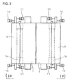
- Figs. 3 and 4 shows a further embodiment of a roll polishing apparatus of the invention.
- parts shown are identical with those in Figs. 1 and 2 except for auxiliary brush rolls 14.
- the auxiliary brush rolls 14 face the outer peripheries of the chilled rolls 1 over the axial lengths thereof, respectively.
- the auxiliary brush rolls 14 are arranged in parallel with the chilled roll 1 and arranged to abut against the outer peripheries of the chilled rolls 1 from below the brush rolls 9, respectively.
- Each of the auxiliary brush rolls 14 has wires made of stainless steel with a diameter of 0.15 mm.
- Each of the brush rolls 9 has a periphery formed such that axially opposite ends of the brush roll are greater in outer diameter than the axially intermediate portion (specifically, length of wires at the axially opposite ends is set to be longer by 1-2 mm than length of the wires at the axially intermediate portion).
- the auxiliary brush rolls 14 are rotatively driven by motors (not shown). Necks of the auxiliary brush rolls 14 are urged toward the chilled rolls 1 by pushing cylinders 13.
- the respective brush rolls 9 are urged to the chilled rolls 1 by the pushing cylinders 10 while being rotated, and at the same time the brush rolls 9 are deformed by the bending cylinders 11 in conformity to the crowns of the chilled rolls 1, respectively, which causes the wires of the brush rolls evenly contact the outer peripheries of the chilled rolls 1 over the axial lengths thereof to wipe off the oxides adhering to the chilled rolls 1, the effect of cooling the solidified shells at the regions becomes not impaired.
- oxides adhering to the outer peripheries of the chilled rolls 1 can be effectively wiped off, and no cracks develop on somewhere around the widthwise ends or intermediate portions of the surfaces of the strip.
- the auxiliary brush rolls 14 are urged by the pushing cylinders 13 to the chilled rolls 1 while being rotated, respectively, the axially opposite ends of the outer peripheries of the chilled rolls 1 are circumferentially polished intensively.
- a roll polishing apparatus of the invention is applicable to various types of twin roll casters.
Landscapes
- Engineering & Computer Science (AREA)
- Mechanical Engineering (AREA)
- Finish Polishing, Edge Sharpening, And Grinding By Specific Grinding Devices (AREA)
- Grinding Of Cylindrical And Plane Surfaces (AREA)
- Continuous Casting (AREA)
Abstract
Description
- The present invention relates to a roll polishing apparatus used for a twin roll caster.
- Known as one of techniques for production of a strip directly from molten metal is twin-roll continuous casting where the molten metal is supplied between a pair of chilled rolls arranged horizontally to deliver the solidified metal as a strip.
-
Fig. 5 shows an example of such twin roll caster comprising a pair ofchilled rolls 1 arranged horizontally and a pair ofside weirs 2 associated with therolls 1. - The chilled
rolls 1 with cooling water passing therethrough are constructed such that a nip G between the rolls may be adjusted to be increased/decreased depending on thickness of thestrip 3 to be produced. - Rotational directions and velocities of the
chilled rolls 1 are set such that outer peripheries of therolls 1 are moved from above toward the nip G at constant velocity. - One and the other of the side weirs 2 surface-contact one and the other ends of the
chilled rolls 1, respectively. In a space defined by thechilled rolls 1 and theside weirs 2, a moltenmetal supply nozzle 4 made of refractory material is arranged to be positioned just above the nip G between the rolls. - The molten
metal supply nozzle 4 has an elongatedtop nozzle trough 6 for reception ofmolten metal 5 and has longitudinal side walls each formed withopenings 7 adjacent to a lower end of the nozzle and extending from thetrough 6 toward outer peripheries of thechilled rolls 1, theopenings 7 being aligned along axes of therolls 1. Thus, themolten metal 5 is poured into thenozzle trough 6 to form amolten metal pool 8 above the nip G between thechilled rolls 1 and in contact with the outer peripheries of therolls 1. - Thus, with the
molten metal pool 8 being formed, thechilled rolls 1 are rotated while being cooled by passing of the cooling water therethrough, so that themolten metal 5 is solidified on the outer peripheries of therolls 1 into shells which are brought together at the nip G into thestrip 3 which in turn is delivered downwardly from therolls 1. - In this case, in order that the
strip 3 produced may have a target thickness, horizontal pushing forces are applied to bearing chocks (not shown) for support of necks on therespective chilled rolls 1 in directions toward each other. - When oxides of, for example, the
molten metal 5 adhere to the outer peripheries of thechilled rolls 1 in themolten metal pool 8, an effect of cooling the solidified shells at oxides-adhering regions becomes insufficient and cracks may develop on the surfaces of thestrip 3. - In order to overcome this, there has been proposed a roll brushing device with brush rolls facing the outer peripheries of the
chilled rolls 1 over axial lengths thereof, respectively. While being rotated by motors, the brush rolls are pushed against thechilled rolls 1 to wipe off the oxides adhering to the outer peripheries of the rolls 1 (see, for example, Patent Literature 1). - In
Patent Literature 1, speaking exaggeratingly, in complementary with thechilled rolls 1 hourglass-shaped or having axially opposite ends greater in outer diameter than axially intermediate portions, the brush rolls are barrel-shaped or have axially opposite ends smaller in outer diameter than axially intermediate portions (difference in outer diameter between the axially opposite ends and the axially intermediate portions in thechilled rolls 1 or in the brush rolls is of the order of 0.4 mm). - [Patent Literature 1]
JP 6-114507A - However, thermal deformations of the
chilled rolls 1 are so complex that, even if the barrel-shaped brush rolls are used, wires of the brush rolls do not always evenly contact the outer peripheries of therolls 1. - Moreover, the brush rolls 9 with their necks being pushed toward the
chilled rolls 1 by thecylinders 10 are rotated in such bent manner, so that the wires of the axially opposite ends of the brush rolls are heavily worn. As a result, at the axially opposite ends of the outer peripheries of thechilled rolls 1, the wires of the brush rolls do not always evenly contact the outer peripheries of therolls 1. - Thus, oxides adhering to somewhere around widthwise ends and intermediate portions of the outer peripheries of the chilled
rolls 1 cannot be completely wiped off by mere use of thebrush rolls 9, and may increase in thickness. As a result, heat removal is lowered at the regions where the oxides are not completely wiped off, resulting in unevenness in heat removal over the width of the strip, so that cracks may develop somewhere around the widthwise ends or intermediate portions of the surfaces of thestrip 3. - The invention has its object to provide a roll polishing apparatus capable of suppressing cracks on surfaces of a strip.
- In order to attain the above object, the invention comprises rotatively driven brush rolls which face outer peripheries of chilled rolls of a twin roll caster over axial lengths thereof, respectively, pushing means for urging said brush rolls wholly to the chilled rolls, respectively, and bending means for deforming said brush rolls in conformity to crowns of the chilled rolls, respectively.
- Specifically, during the production of a strip, the brush rolls are urged by the pushing means to the chilled rolls and are deformed by the bending means in conformity to the crowns of the chilled rolls, respectively, so as to keep the wires on the brush rolls evenly contacting the outer peripheries of the chilled rolls over axial lengths thereof, respectively.
- In addition, each of the brush rolls has a periphery formed such that axially opposite ends of the brush roll are smaller in outer diameter than an axially intermediate portion. Thus, convex deformation of the brush rolls toward the chilled rolls causes tips of the wires on the axially opposite ends of the brush rolls to properly contact the outer peripheries of the chilled rolls.
- Further, the apparatus comprises, independently of the brush rolls, rotatively driven auxiliary brush rolls which face the outer peripheries of the chilled rolls, respectively, and pushing means for urging said auxiliary brush rolls wholly to the chilled rolls, respectively, the outer peripheries of the chilled rolls being also polished by the auxiliary brush rolls, respectively.
- The auxiliary brush rolls used are those which face the outer peripheries of the chilled roll over the lengths thereof, respectively, each of said auxiliary brush rolls having a periphery such that the axially opposite ends of the brush roll is greater in outer diameter than the axially intermediate portion.
- According to a roll polishing apparatus of the invention, the following effects and advantages can be obtained.
- (1) When the brush rolls are deformed in their axes by the bending means in conformity to the crowns of the chilled rolls, the wires of the brush rolls evenly contact the outer peripheries of the chilled rolls over the axial lengths thereof, so that the oxides adhering to the outer peripheries of the chilled rolls can be effectively wiped off, and no cracks develop somewhere around the widthwise edges and intermediate portions of the surfaces of the strip.
- (2) Since the axially opposite ends of each of the brush rolls are smaller in outer diameter than axially intermediate portion of the brush roll, convex deformation of the brush rolls to the chilled rolls causes tips of the wires of the axially opposite ends of the brush rolls to properly contact the outer peripheries of the chilled rolls, which ensures wipe-off of the oxides at the regions.
- (3) When the auxiliary brush rolls are provided independently of the brush rolls, specific areas on the outer peripheries of the chilled rolls can be circumferentially polished intensively by the auxiliary brush rolls.
-
-
Fig. 1 is a schematic plan view showing an embodiment of a roll polishing apparatus according to the invention; -
Fig. 2 is a view looking in the direction of arrows II inFig. 1 ; -
Fig. 3 is a schematic plan view of a further embodiment of a roll polishing apparatus according to the invention; -
Fig. 4 is a view looking in the direction of arrows IV inFig. 3 ; and -
Fig. 5 is a schematic view showing a conventional twin roll caster looking axially of chilled rolls. -
- 1
- chilled roll
- 9
- brush roll
- 10
- pushing cylinder (pushing means)
- 11
- bending cylinder (bending means)
- 12
- auxiliary brush roll
- 13
- pushing cylinder (pushing means)
- 14
- auxiliary brush roll
- Next, embodiments of the invention will be described in conjunction with the drawings.
-
Figs. 1 and2 show an embodiment of a roll polishing apparatus according to the invention which comprisesbrush rolls 9 facing outer peripheries ofchilled rolls 1 in a twin roll caster over axial lengths thereof, respectively, pushingcylinders 10 for urging necks of thebrush rolls 9 toward the chilledrolls 1, respectively, bendingcylinders 11 for urging the necks away from thechilled rolls 1, respectively,auxiliary brush rolls 12 independently of thebrush rolls 9 and facing independently one and the other axial ends of the outer peripheries of thechilled rolls 1, respectively, and pushingcylinders 13 for urging necks on theauxiliary brush rolls 12 toward thechilled rolls 1, respectively. - The
brush rolls 9 are in parallel with thechilled rolls 1 and are arranged to horizontally abut against the outer peripheries of thechilled rolls 1 at positions diametrically away from the nip G (seeFig. 5 ), respectively. - Each of the
brush rolls 9 has wires made of stainless steel and with a diameter of 0.15 mm; each of thebrush rolls 9 has a periphery formed such that axially opposite roll ends of the brush roll are smaller in outer diameter than axially intermediate portion in conformity with thechilled roll 1. - The pushing
cylinders 10 horizontally and diametrically push the necks of thebrush rolls 9 somewhere around their primal ends, respectively, and thebending cylinders 11 horizontally push the necks of thebrush rolls 9 somewhere around their distal ends, respectively. - The
auxiliary brush rolls 12 are in parallel with thechilled rolls 1 and arranged to abut against the outer peripheries of thechilled rolls 1 from below thebrush rolls 9, respectively. - The auxiliary brush rolls 12 also have wires made of stainless steel like the above-mentioned brush rolls 9.
- The pushing
cylinders 13 push necks of the auxiliary brush rolls 12 toward the axes of thechilled rolls 1, respectively. - The brush rolls 9 and the auxiliary brush rolls 12 are rotatively driven by motors (not shown), respectively.
- Specifically, during production of a strip the respective brush rolls 9 are urged to the
chilled rolls 1 by the pushingcylinders 10 while being rotated, and at the same time the brush rolls 9 are deformed by the bendingcylinders 11 in conformity to the crowns of thechilled rolls 1, respectively, which causes the wires of the brush rolls evenly contact the outer peripheries of thechilled rolls 1 over the axial lengths thereof to wipe off the oxides adhering to thechilled rolls 1, respectively, the effect of cooling the solidified shells at the regions becomes not impaired. - The oxides are efficiently wiped off when distance between the axis of the
chilled roll 1 and the axis of thebrush roll 9 is set to be shorter by 1 mm than a sum of a radius of thechilled roll 1 and radius of thebrush roll 9. - Since each of the brush rolls 9 has the periphery formed such that axially opposite ends are smaller in outer diameter than the axially intermediate portion, convex deformation of the brush rolls 9 against the
chilled rolls 1 causes the wires of the brush rolls 9 at their axially opposite ends to properly contact the outer peripheries of thechilled rolls 1, respectively, facilitating the wipe-off of the oxides. - Thus, the oxides adhering to the outer peripheries of the
chilled rolls 1 can be effectively wiped off, and no cracks develop somewhere around the widthwise ends or intermediate portions of the surfaces of the strip. - In addition, the auxiliary brush rolls 12 independently of the brush rolls 9 are urged by the pushing
cylinders 13 to thechilled rolls 1 while being rotated, the axially opposite ends of the outer peripheries of thechilled roll 1 are circumferentially polished intensively. -
Figs. 3 and4 shows a further embodiment of a roll polishing apparatus of the invention. In the figures, parts shown are identical with those inFigs. 1 and2 except for auxiliary brush rolls 14. - Independently of the brush rolls 9, the auxiliary brush rolls 14 face the outer peripheries of the
chilled rolls 1 over the axial lengths thereof, respectively. - The auxiliary brush rolls 14 are arranged in parallel with the
chilled roll 1 and arranged to abut against the outer peripheries of thechilled rolls 1 from below the brush rolls 9, respectively. - Each of the auxiliary brush rolls 14 has wires made of stainless steel with a diameter of 0.15 mm. Each of the brush rolls 9 has a periphery formed such that axially opposite ends of the brush roll are greater in outer diameter than the axially intermediate portion (specifically, length of wires at the axially opposite ends is set to be longer by 1-2 mm than length of the wires at the axially intermediate portion).
- The auxiliary brush rolls 14 are rotatively driven by motors (not shown). Necks of the auxiliary brush rolls 14 are urged toward the
chilled rolls 1 by pushingcylinders 13. - Specifically, during the production of a strip the respective brush rolls 9 are urged to the
chilled rolls 1 by the pushingcylinders 10 while being rotated, and at the same time the brush rolls 9 are deformed by the bendingcylinders 11 in conformity to the crowns of thechilled rolls 1, respectively, which causes the wires of the brush rolls evenly contact the outer peripheries of thechilled rolls 1 over the axial lengths thereof to wipe off the oxides adhering to thechilled rolls 1, the effect of cooling the solidified shells at the regions becomes not impaired. - Thus, oxides adhering to the outer peripheries of the
chilled rolls 1 can be effectively wiped off, and no cracks develop on somewhere around the widthwise ends or intermediate portions of the surfaces of the strip. - In addition, independently of the brush rolls 9, the auxiliary brush rolls 14 are urged by the pushing
cylinders 13 to thechilled rolls 1 while being rotated, respectively, the axially opposite ends of the outer peripheries of thechilled rolls 1 are circumferentially polished intensively. - It is to be understood that a roll polishing apparatus of the invention is not limited to the above embodiments and that various changes and modifications may be made without departing from the scope of the invention.
- A roll polishing apparatus of the invention is applicable to various types of twin roll casters.
Claims (4)
- A roll polishing apparatus, characterized by comprising rotatively driven brush rolls which face outer peripheries of chilled rolls of a twin roll caster over axial lengths thereof, respectively, pushing means for urging said brush rolls wholly to the chilled rolls, respectively, and bending means for deforming said brush rolls in conformity to crowns of the chilled rolls, respectively.
- A roll polishing apparatus as claim in claim 1, wherein each of the brush rolls has a periphery formed such that axially opposite ends of the brush roll are smaller in outer diameter than an axially intermediate portion.
- A roll polishing apparatus as claimed in claim 1 or 2, wherein it comprises, independently of the brush rolls, rotatively driven auxiliary brush rolls which face the outer peripheries of the chilled rolls, respectively, and pushing means for urging said auxiliary brush rolls wholly to the chilled rolls, respectively.
- A roll polishing apparatus as claimed in claim 3, wherein said auxiliary brush rolls used are those which face the outer peripheries of the chilled roll over axial lengths thereof, respectively, each of said auxiliary brush rolls having a periphery formed such that the axially opposite ends of the brush roll is greater in outer diameter than the axially intermediate portion.
Applications Claiming Priority (1)
| Application Number | Priority Date | Filing Date | Title |
|---|---|---|---|
| PCT/JP2008/000664 WO2009116119A1 (en) | 2008-03-21 | 2008-03-21 | Roll polishing apparatus |
Publications (2)
| Publication Number | Publication Date |
|---|---|
| EP2253425A1 true EP2253425A1 (en) | 2010-11-24 |
| EP2253425A4 EP2253425A4 (en) | 2011-12-14 |
Family
ID=41090541
Family Applications (1)
| Application Number | Title | Priority Date | Filing Date |
|---|---|---|---|
| EP08720546A Withdrawn EP2253425A4 (en) | 2008-03-21 | 2008-03-21 | Roll polishing apparatus |
Country Status (6)
| Country | Link |
|---|---|
| US (1) | US8087448B2 (en) |
| EP (1) | EP2253425A4 (en) |
| JP (1) | JP5104943B2 (en) |
| KR (1) | KR101228358B1 (en) |
| CN (1) | CN101977728B (en) |
| WO (1) | WO2009116119A1 (en) |
Cited By (1)
| Publication number | Priority date | Publication date | Assignee | Title |
|---|---|---|---|---|
| CN103158430A (en) * | 2011-12-08 | 2013-06-19 | 天津利福特电梯部件有限公司 | Escalator handrail automatic hairline-cutting machine |
Families Citing this family (4)
| Publication number | Priority date | Publication date | Assignee | Title |
|---|---|---|---|---|
| CN102848302A (en) * | 2011-07-01 | 2013-01-02 | 上海格林赛高新材料有限公司 | Strip material surface treatment device |
| CN110087799B (en) * | 2016-12-26 | 2021-03-23 | 宝山钢铁股份有限公司 | Casting roll surface cleaning device and method |
| CN107081671B (en) * | 2017-06-28 | 2023-07-04 | 青岛云路先进材料技术股份有限公司 | Online polishing device |
| CN113043151B (en) * | 2021-04-15 | 2023-12-01 | 成都倍特建筑安装工程有限公司 | Steel pipe polishing device for building based on inertia polishing |
Family Cites Families (17)
| Publication number | Priority date | Publication date | Assignee | Title |
|---|---|---|---|---|
| JPS5292855A (en) * | 1976-02-02 | 1977-08-04 | Hitachi Ltd | Method and device for controlling form in aluminium rolling machine |
| JPS58163509A (en) * | 1982-03-25 | 1983-09-28 | Ishikawajima Harima Heavy Ind Co Ltd | Grinding equipment of rolling roll |
| JPS58223556A (en) * | 1982-06-15 | 1983-12-26 | Mitsubishi Heavy Ind Ltd | Grinding of roll |
| JPS6014835A (en) | 1983-07-08 | 1985-01-25 | 松下電器産業株式会社 | Cutter for cooking machine |
| JPS6014835U (en) * | 1983-07-11 | 1985-01-31 | 昭和電線電纜株式会社 | Roller grinding device |
| NL8702448A (en) | 1987-10-14 | 1989-05-01 | Dyneema Vof | SURFACE TREATMENT OF POLYOLEFINE ARTICLES. |
| JPH0716770B2 (en) * | 1990-02-02 | 1995-03-01 | 新日本製鐵株式会社 | Continuous casting equipment for thin cast pieces |
| JPH06114507A (en) * | 1992-10-09 | 1994-04-26 | Nippon Steel Corp | Brush device for continuous casting drum |
| AUPP414398A0 (en) * | 1998-06-17 | 1998-07-09 | Bhp Steel (Jla) Pty Limited | Strip casting apparatus |
| US6886623B2 (en) * | 1998-06-17 | 2005-05-03 | Castrip Llc | Strip casting apparatus |
| JP2001058245A (en) * | 1999-08-23 | 2001-03-06 | Nippon Steel Corp | Cooling drum brushing method |
| KR100584751B1 (en) * | 2001-12-22 | 2006-05-30 | 주식회사 포스코 | Gas layer thickness control device of casting roll surface of twin roll sheet casting machine |
| US20030198857A1 (en) * | 2002-04-05 | 2003-10-23 | Mcmanus Edward C. | Graphite laminate fuel cell plate |
| US7404431B2 (en) * | 2002-06-04 | 2008-07-29 | Nucor Corporation | Production of thin steel strip |
| DE10333215A1 (en) * | 2003-07-22 | 2005-02-17 | Sms Demag Ag | Shaping roller cleaning brush for working rollers in metal, especially aluminum, hot strip mills comprises fitting shape of brush coating and shape of cleaning brush according to shape of roller |
| FR2881353B1 (en) * | 2005-02-03 | 2008-12-05 | Vygon Sa | IMPROVEMENT TO PUNCTURAL BITS AND CATHETER TUBES |
| JP5320733B2 (en) | 2007-12-28 | 2013-10-23 | 株式会社Ihi | Cooling roll cleaning device |
-
2008
- 2008-03-21 KR KR1020107019583A patent/KR101228358B1/en not_active Expired - Fee Related
- 2008-03-21 WO PCT/JP2008/000664 patent/WO2009116119A1/en not_active Ceased
- 2008-03-21 EP EP08720546A patent/EP2253425A4/en not_active Withdrawn
- 2008-03-21 JP JP2010503675A patent/JP5104943B2/en not_active Expired - Fee Related
- 2008-03-21 CN CN200880128191.2A patent/CN101977728B/en not_active Expired - Fee Related
- 2008-03-21 US US12/867,848 patent/US8087448B2/en not_active Expired - Fee Related
Cited By (1)
| Publication number | Priority date | Publication date | Assignee | Title |
|---|---|---|---|---|
| CN103158430A (en) * | 2011-12-08 | 2013-06-19 | 天津利福特电梯部件有限公司 | Escalator handrail automatic hairline-cutting machine |
Also Published As
| Publication number | Publication date |
|---|---|
| US8087448B2 (en) | 2012-01-03 |
| EP2253425A4 (en) | 2011-12-14 |
| CN101977728A (en) | 2011-02-16 |
| US20110119858A1 (en) | 2011-05-26 |
| KR101228358B1 (en) | 2013-02-01 |
| KR20100102748A (en) | 2010-09-24 |
| JP5104943B2 (en) | 2012-12-19 |
| WO2009116119A1 (en) | 2009-09-24 |
| JPWO2009116119A1 (en) | 2011-07-21 |
| CN101977728B (en) | 2012-12-05 |
Similar Documents
| Publication | Publication Date | Title |
|---|---|---|
| US8087448B2 (en) | Roll polishing apparatus | |
| WO2024066742A1 (en) | Method for mitigating local high points of hot-rolled thin steel strip | |
| JP4745967B2 (en) | Roll cleaning brush modeling method and cleaning brush formed by the method | |
| CN101541446A (en) | Improvement apparatus of surface roughness defect of hot/cold rolled stainless steel coils and the method thereof | |
| WO2008106744A1 (en) | Method for controlling thickness profile of strip | |
| EP0688620A2 (en) | Twin roll caster | |
| JP3698001B2 (en) | Slide bearing device for rolls in continuous molten metal plating bath | |
| CN201136046Y (en) | A roller surface cleaning device for twin-roll thin strip continuous casting | |
| WO2014013717A1 (en) | Cooling rollers for twin-roller casting device | |
| US8316920B2 (en) | Brush roll for casting roll | |
| JP3077625B2 (en) | Hot rolling roll cooling method | |
| JP2000280049A (en) | Twin-drum continuous casting method and apparatus | |
| JP2008114281A (en) | Roll grinding machine | |
| JPS6234618A (en) | Brush device for removing scale from steel materials | |
| JP3591165B2 (en) | Metal strip transfer method and transfer equipment | |
| EP0191199A1 (en) | Apparatus for cooling a work roll in a rolling mill for rolling metal strip | |
| JPS6226858B2 (en) | ||
| KR100605677B1 (en) | Roll surface brushing method in sheet casting machine | |
| JPS62176650A (en) | Device for cleaning surface of cooling roll for producing rapid cooled thin hoop | |
| JP2002160012A (en) | Removing device for rolling oil of metal strip | |
| KR20090060736A (en) | Brush roll of twin roll sheet casting machine | |
| KR100782689B1 (en) | Manufacturing method of high quality cast steel in twin roll sheet metal manufacturing process | |
| JPH0790246B2 (en) | Direct slab rolling method | |
| JPH10166110A (en) | Roll brush reuse method in twin roll continuous casting method | |
| JP2007203317A (en) | Thermal crown control device, rolling mill, and metal strip manufacturing method using the rolling mill |
Legal Events
| Date | Code | Title | Description |
|---|---|---|---|
| PUAI | Public reference made under article 153(3) epc to a published international application that has entered the european phase |
Free format text: ORIGINAL CODE: 0009012 |
|
| 17P | Request for examination filed |
Effective date: 20100828 |
|
| AK | Designated contracting states |
Kind code of ref document: A1 Designated state(s): AT BE BG CH CY CZ DE DK EE ES FI FR GB GR HR HU IE IS IT LI LT LU LV MC MT NL NO PL PT RO SE SI SK TR |
|
| AX | Request for extension of the european patent |
Extension state: AL BA MK RS |
|
| DAX | Request for extension of the european patent (deleted) | ||
| RIN1 | Information on inventor provided before grant (corrected) |
Inventor name: FUKASE, HISAHIKO Inventor name: OSADA, SHIRO Inventor name: OTSUKA, HIROYUKI Inventor name: NAKAYAMA, KATSUMI |
|
| A4 | Supplementary search report drawn up and despatched |
Effective date: 20111114 |
|
| RIC1 | Information provided on ipc code assigned before grant |
Ipc: B24B 27/033 20060101ALI20111108BHEP Ipc: B21B 28/04 20060101ALI20111108BHEP Ipc: B22D 11/06 20060101ALI20111108BHEP Ipc: B24B 5/37 20060101AFI20111108BHEP |
|
| STAA | Information on the status of an ep patent application or granted ep patent |
Free format text: STATUS: THE APPLICATION IS DEEMED TO BE WITHDRAWN |
|
| 18D | Application deemed to be withdrawn |
Effective date: 20120710 |