EP2253408A1 - Arc welding method - Google Patents
Arc welding method Download PDFInfo
- Publication number
- EP2253408A1 EP2253408A1 EP10161541A EP10161541A EP2253408A1 EP 2253408 A1 EP2253408 A1 EP 2253408A1 EP 10161541 A EP10161541 A EP 10161541A EP 10161541 A EP10161541 A EP 10161541A EP 2253408 A1 EP2253408 A1 EP 2253408A1
- Authority
- EP
- European Patent Office
- Prior art keywords
- welding
- wire
- polarity
- arc
- state
- Prior art date
- Legal status (The legal status is an assumption and is not a legal conclusion. Google has not performed a legal analysis and makes no representation as to the accuracy of the status listed.)
- Withdrawn
Links
Images




Classifications
-
- B—PERFORMING OPERATIONS; TRANSPORTING
- B23—MACHINE TOOLS; METAL-WORKING NOT OTHERWISE PROVIDED FOR
- B23K—SOLDERING OR UNSOLDERING; WELDING; CLADDING OR PLATING BY SOLDERING OR WELDING; CUTTING BY APPLYING HEAT LOCALLY, e.g. FLAME CUTTING; WORKING BY LASER BEAM
- B23K9/00—Arc welding or cutting
- B23K9/16—Arc welding or cutting making use of shielding gas
- B23K9/173—Arc welding or cutting making use of shielding gas and of a consumable electrode
-
- B—PERFORMING OPERATIONS; TRANSPORTING
- B23—MACHINE TOOLS; METAL-WORKING NOT OTHERWISE PROVIDED FOR
- B23K—SOLDERING OR UNSOLDERING; WELDING; CLADDING OR PLATING BY SOLDERING OR WELDING; CUTTING BY APPLYING HEAT LOCALLY, e.g. FLAME CUTTING; WORKING BY LASER BEAM
- B23K9/00—Arc welding or cutting
- B23K9/06—Arrangements or circuits for starting the arc, e.g. by generating ignition voltage, or for stabilising the arc
- B23K9/067—Starting the arc
-
- B—PERFORMING OPERATIONS; TRANSPORTING
- B23—MACHINE TOOLS; METAL-WORKING NOT OTHERWISE PROVIDED FOR
- B23K—SOLDERING OR UNSOLDERING; WELDING; CLADDING OR PLATING BY SOLDERING OR WELDING; CUTTING BY APPLYING HEAT LOCALLY, e.g. FLAME CUTTING; WORKING BY LASER BEAM
- B23K9/00—Arc welding or cutting
- B23K9/12—Automatic feeding or moving of electrodes or work for spot or seam welding or cutting
- B23K9/124—Circuits or methods for feeding welding wire
Definitions
- the present invention relates to a consumable electrode type arc welding method, and particularly to an arc welding method which performs thick-plate welding by means of large current.
- tandem welding in which the number of torches has been increased to the plural number is disclosed (for example, refer to JP-A-2004-243372 ).
- JP-A-2004-243372 measure of increasing the deposition amount by adding a torch to two torches, that is, by using three torches has been disclosed.
- the increase in the number of torches enables the electric current produced per torch to decrease, so that there are advantages that the strong magnetic field is not generated and the weld penetration does not become too deep.
- a welding method has been disclosed in which a flux-cored wire or a metal-cored wire having the large diameter is used, and the amount of spatter is reduced by performing one-pass execution by tandem welding of a leading electrode and a trailing electrode by the welding current of AC (alternating current) 600 to 1900A, or by performing multi-pass execution by a single electrode (for example, refer to JP-A-11-147175 ).
- JP-A-2004-243372 and JP-A-11-147175 can respond to such the problems produced in the state where the current and welding-wire feeding speed are large.
- tandem welding As described in JP-A-2004-243372 , it is extremely difficult to execute welding while keeping both of the leading electrode and the trailing electrode at the optimum posture for the welding portion including a curve. Therefore, the tandem welding is not easy to be applied to the work having many curves.
- JP-A-11-147175 a combined wire such as a flux-cored wire or a metal-cored wire is used as the welding wire. Since these wires are more expensive than a solid wire, there is a problem in cost.
- the invention has been made in view of such the problems accompanied with large-current/high deposition welding for thick plate, and has an object to provide an arc welding method in which large-current/high deposition which is equal to or more than that in case of using plural torches is realized by a single torch while keeping high-speed wire feeding, and stable welding is performed by suppressing high-speed rotation of a wire tip and reducing greatly generation of spatter.
- a consumable electrode type arc welding method for generating arc between a plate-shaped work and a welding wire by a mixed shield gas including argon gas to weld the plate-shaped work, including:
- a welding wire of 1.2 to 1.6 mm in diameter and the welding current of 600A or more are used.
- a wire tip starts to rotate at a high speed under this condition.
- a wire tip starts to rotate at a high speed. Since the high-speed rotation of the wire tip causes the spatter as described before, it is an essential condition to suppress this high-speed rotation of the wire tip in order to perform stable welding by the large current.
- the inventor of this invention has investigated the mechanism in which the wire tip starts to rotate at a high speed in the large current area, with the result that he has noticed that the following phenomena (A) and (B) exist in the high-speed rotation mechanism.
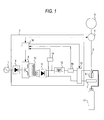
- Fig. 1 is a schematic diagram showing the constitution of a welding apparatus which executes an arc welding method of the invention.
- a welding power supply 2 to which electric power is supplied from a three-phase AC (alternating-current) power supply 1 controls a wire feeding device 4 thereby to control the supply speed of a wire 3 supplied from a wire spool 5 toward a work 7, and supplies high power through a power supply device 6 to the wire 3 thereby to generate arc discharge between the wire 3 and the work 7.
- a welding power supply 2 to which electric power is supplied from a three-phase AC (alternating-current) power supply 1 controls a wire feeding device 4 thereby to control the supply speed of a wire 3 supplied from a wire spool 5 toward a work 7, and supplies high power through a power supply device 6 to the wire 3 thereby to generate arc discharge between the wire 3 and the work 7.
- the shield gas is supplied so as to jet from a tip of the wire 3 toward the work 7.
- the shield gas uses a mixed shield gas including argon of 80% and CO 2 of 20%.
- the welding power supply 2 includes a converter 8 to a control part 16.
- the direct current is supplied to an inverter 9 from the converter 8 which converts the three-phase alternating current into the direct current
- the inverter 9 converts its DC current into the high-frequency AC current.
- a reference numeral 13 is a EP (reverse polarity)/EN (Positive polarity) switching part, which, while setting the reverse (EP) polarity in which the wire side is the positive polarity and the work side is the negative polarity, or the positive (EN) polarity in which the wire side is the negative polarity and the work side is the positive polarity, and switching the EP polarity and the EN polarity, supplies the electric power between the power supply device 6 for the wire and the work 7.
- a reference numeral 14 is a voltage detecting sensor which detects the welding voltage between the wire and the work, and a reference numeral 15 is a current detecting sensor which detects the welding current flowing between the wire and the work.
- Each output from the voltage detecting sensor 14 and the current detecting sensor 15 is input to the control part 16.
- the control part 16 controls the inverter 9 inside the welding power supply on the basis of each output from the both sensors. Further, in the wire feeding device 4, an encoder and a motor, which are not shown herein, are incorporated, and the control part 16 controls this motor thereby to feed the wire 3 from the wire spool 5 to the work 7 side at the predetermined wire-feeding speed.
- the control part 16 in addition, instructs the EP/EN switching part 13 on switching.
- the mixed shield gas of argon and CO 2 is supplied from the gas cylinder 17, and direct-current arc welding is performed using a welding wire of 1.4 mm in diameter in the reverse polarity (EP polarity) in which the wire 3 side is the positive polarity and the work 7 side is the negative polarity.
- An arc state of the wire tip portion in case of such the consumable electrode type arc welding will be described with reference to a schematic diagram of Fig. 2 .
- the tip of the wire 3 is heated by heat of the arc, whereby a wire tip droplet 18 is formed.
- the wire tip droplet 18 is a melted metal ball.
- the wire tip droplet 18 is attaching to the tip of the wire 3 by surface tension and viscosity, as the metal ball grows, it drops toward the work 7 by the pinch force of the welding current and the force of gravitation.
- the amount of wire fed from the wire feeding device 4 balances with the wire amount of the wire tip droplet 18 dropping toward the work 7, whereby the arc length of an arc 19 becomes constant.
- Fig. 4 is a schematic diagram of an arc state in the EP polarity
- Fig. 5 is a schematic diagram of an arc state in the EN polarity.
- the shape of the wire tip droplet 18 is the same as that in Fig. 2 .
- the wire tip droplet 18 becomes an inverted cone droplet 18' extending downward, which is different from the case in Fig. 4 .
- the wire tip portion repeats such the droplet state 18 in Fig.
- the switching frequency between the EP polarity and the EN polarity that is, the AC (alternating-current) frequency is set to 10Hz or more under the condition where the wire feeding speed is 25 m/min. or more, there is an advantage that the arc rotation stops.
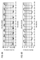
- the current waveform in the welding test time at the AC frequency of 20Hz is shown in Fig. 6A
- the voltage waveform in that time is shown in Fig. 6B
- other detailed welding conditions in that time are shown in Fig. 7A .
- the welding conditions are that: (1) the diameter of the used wire is 1.4 mm, (2) the wire feeding speed is 35 m/min., (3) the frequency of the alternating current supplied to the wire is 20Hz, (4) the AC rate is 50%, (5) the welding current is 670A, (6) the welding voltage is 42V, and (7) the thickness of a work to be welded is 12 mm.
- the "welding current” in (5) means an average value of the AC current. Namely, though the peak of the current waveform in Fig.
- the current waveform in the welding test time at the AC frequency of 40Hz is shown in Fig. 8A
- the voltage waveform in that time is shown in Fig. 8B
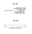
- other detailed welding conditions in that time are shown in Fig. 9A .
- the welding conditions are that: (1) the diameter of the used wire is 1.4 mm, (2) the wire feeding speed is 35 m/min., (3) the frequency of the alternating current supplied to the wire is 40Hz, (4) the AC rate is 50%
- the welding current is 670A
- (6) the welding voltage is 42V
- the thickness of a work to be welded is 12 mm.
- the definition of "welding current" in (5) is the same as that in Fig. 7 .
- Fig. 9B the external appearance of the welding bead produced in the welding test is shown in an external view of Fig. 9B .
- the welding bead in Fig. 9 at the AC frequency of 40Hz does not scatter around as spatters, and further the bead formed on the work just under the wire has a convex shape which is narrower in width and larger in height than the conventional bead. Therefore, the formed bead is satisfactory.
- the welding bead in Fig. 9B at the AC frequency of 40Hz is slightly convex, compared with the welding bead in Fig. 7B at the AC frequency of 20Hz is that: since the number in which the current/voltage becomes zero per unit time is large in case that the AC frequency is high, the heat quantity to be inputted to the work decreases, it is thought.
- Embodiment 2 the EP polarity is switched to the EN polarity in response to the wire feeding speed.
- control part 16 instructs the EP/EN switching portion 13 to keep the EP polarity.
- the control part 16 instructs the EP/EN switching portion 13 to switch the EP polarity to the EN polarity.
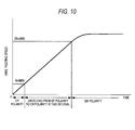
- Fig. 10 is a graph showing timing in which the EP polarity is switched to the EN polarity with the increase of wire feeding speed.
- the wire feeding speed is as high as to be 25 m/min. and more, the arc is generated also from the position ascending up to the upper portion of the wire from the wire tip by keeping the state of the EN polarity, and the arc does not concentrate on the wire tip. Therefore, the rotation of the wire tip droplet and the arc rotation are not similarly produced.
- this switching may be performed in response to the elapsed time from the wire feeding start. Specifically, at the first of the wire feeding start, the EP polarity is kept; and when the predetermined time (about several seconds) has passed from the wire feeding start and the wire feeding speed has increased, switching of the EP polarity to the EN polarity is performed.
- Embodiment 1 and Embodiment 2 have been described with reference to the test using the welding wire of 1.4 mm in diameter, also in the case where the wire diameter is about 1.4 mm (1.2 to 1.6 mm), the similar advantage can be obtained.
- the range of the current density flowing into the wire in which the advantage of the invention is obtained becomes 600A/ ( ⁇ (0.8mm) 2 ) ⁇ 300A/ mm 2 or more.
- the ratio of argon and CO 2 composing the mixed shield gas used in the Embodiment 1 and Embodiment 2 is 80% to 20%.
- a shield gas in which helium or oxygen is mixed by several % in addition to CO 2 may be used.
Landscapes
- Engineering & Computer Science (AREA)
- Physics & Mathematics (AREA)
- Plasma & Fusion (AREA)
- Mechanical Engineering (AREA)
- Arc Welding In General (AREA)
- Arc Welding Control (AREA)
Abstract
making a state of reverse polarity in which the polarity of the welding wire is positive at the welding start time, and
switching at least once to a state of positive polarity in which the polarity of the welding wire is negative.
Description
- This application is based on and claims priority under 35 U.S.C. §119 from Japanese Patent Application No.
2009-118573 filed on May 15, 2009 - The present invention relates to a consumable electrode type arc welding method, and particularly to an arc welding method which performs thick-plate welding by means of large current.
- In arc welding for the work of such a thick-plate work that the thickness is 8 mm or more, increase of current and high deposition are demanded in order to improve efficiency and productivity of the welding operation. To meet such the demand, it is necessary to increase the welding-wire supplying amount per unit time as much as possible.
- Therefore, methods of increasing the welding-wire feeding speed and further supplying the large current to the welding wire have been recently investigated.
- In order to subject thick plates to high deposition, tandem welding in which the number of torches has been increased to the plural number is disclosed (for example, refer to
JP-A-2004-243372
InJP-A-2004-243372
Further, for thick-plate welding, a welding method has been disclosed in which a flux-cored wire or a metal-cored wire having the large diameter is used, and the amount of spatter is reduced by performing one-pass execution by tandem welding of a leading electrode and a trailing electrode by the welding current of AC (alternating current) 600 to 1900A, or by performing multi-pass execution by a single electrode (for example, refer toJP-A-11-147175 - However, such the related arts, since the welding-wire feeding speeds are 7.5 m/min. in
JP-A-11-147175 JP-A-2004-243372 - Further, in consumable electrode type arc welding by the large current, in case that the welding-wire feeding speed is increased, such a phenomenon is confirmed that the strong magnetic field is generated by the welding current thereby to cause the arc to start rotating and the wire tip rotates rapidly at a high speed with this arc rotation. For example, in MAG (Metal Active Gas) welding by means of a wire of 1.4 mm in diameter, in case that welding is performed in a state where the welding current exceeds 600A and the welding-wire feeding speed is 25 m/min. or more, the arc starts to rotate. When the wire tip rotates at the high speed, the wire tip is brown off by the centrifugal force produced by the rotation and spatter is generated, so that welding itself becomes unstable.
- On the other hand, in case that the arc length is decreased in order to reduce the influence of the arc rotation under the state where the current and welding-wire feeding speed are large, the arc power becomes strong, so that there is produced a problem that the weld penetration in the work formed by the arc power becomes too deep.
- Neither of the related arts described in
JP-A-2004-243372 JP-A-11-147175 - Further, for such tandem welding as described in
JP-A-2004-243372 - Further, since welding by the respective torches interfere with each other, special control for avoiding the interference between the torches is required. Furthermore, it is not easy to set the welding condition of each torch. Therefore, application of the plural torches to an automation line of welding has limitation.
- Further, in
JP-A-11-147175 - The invention has been made in view of such the problems accompanied with large-current/high deposition welding for thick plate, and has an object to provide an arc welding method in which large-current/high deposition which is equal to or more than that in case of using plural torches is realized by a single torch while keeping high-speed wire feeding, and stable welding is performed by suppressing high-speed rotation of a wire tip and reducing greatly generation of spatter.
- In order to solve the above problem, the invention is constituted as follows.
According to a first aspect of the invention, there is provided a consumable electrode type arc welding method for generating arc between a plate-shaped work and a welding wire by a mixed shield gas including argon gas to weld the plate-shaped work, including: - making a state of reverse polarity in which the polarity of the welding wire is positive at the welding start time, and
- switching at least once to a state of positive polarity in which the polarity of the welding wire is negative.
- According to the above first to fifth aspects, it is possible to realize stable consumable electrode type arc welding in which the high-speed rotation of a wire tip is suppressed while large-current/high deposition which is equal to or more than that in case of using plural torches is being realized for the thick-plate work by a single torch, and the generation of spatter is greatly reduced.
-
-
Fig. 1 is a schematic diagram showing the constitution of a welding apparatus which executes an arc welding method of the invention; -
Fig. 2 is a schematic diagram showing an arc state of a wire tip portion in case that DC (direct current) arc welding is performed with EP polarity (reverse polarity); -
Fig. 3A and 3B are diagrams showing a state where a wire tip droplet and arc rotate with increase of the welding-wire feeding speed; -
Fig. 4 is a schematic diagram showing an arc state of the wire tip portion in the EP polarity; -
Fig. 5 is a schematic diagram showing an arc state of the wire tip portion in EN polarity (positive polarity); -
Fig. 6A is a diagram showing a welding current waveform in case that AC (alternating current) frequency is 20Hz; -
Fig. 6B is a diagram showing a welding voltage waveform in case that AC frequency is 20Hz; -
Fig. 7A is a diagram showing welding conditions including a case in which AC frequency is 20Hz; -
Fig. 7B is an external view of a bead welded under the welding condition 7(A); -
Fig. 8A is a diagram showing a welding current waveform in case that AC frequency is 40Hz; -
Fig. 8B is a diagram showing a welding voltage waveform in case that AC frequency is 40Hz; -
Fig. 9A is a diagram showing welding conditions including a case in which AC frequency is 40Hz; -
Fig. 9B is an external view of a bead welded under the welding condition 9(A); and -
Fig. 10 is a graph showing the way of switching from the EP polarity to the EN polarity in response to the wire feeding speed. - Regarding the invention in which large-current/high deposition which is equal to or more than that in case of using plural torches is realized by a single torch while keeping high-speed wire feeding, and stable welding is performed by suppressing high-speed rotation of a wire tip and reducing greatly generation of spatter, its embodiments will be described below with reference to drawings.
- In this embodiment, in consumable electrode type arc welding for the work having a thickness of 8 mm or more by use of a mixed shielding gas of argon and CO2, a welding wire of 1.2 to 1.6 mm in diameter and the welding current of 600A or more are used.
- (In case that the welding condition in
Embodiment 1 is not changed, a wire tip starts to rotate at a high speed under this condition.)
In case that welding is performed at a wire-feeding speed of 25 m/min. or more under the above condition, a wire tip starts to rotate at a high speed. Since the high-speed rotation of the wire tip causes the spatter as described before, it is an essential condition to suppress this high-speed rotation of the wire tip in order to perform stable welding by the large current. - The inventor of this invention has investigated the mechanism in which the wire tip starts to rotate at a high speed in the large current area, with the result that he has noticed that the following phenomena (A) and (B) exist in the high-speed rotation mechanism.
- (A) Since a large magnetic field is generated around the welding wire in the large current state, the arc and the wire tip start to rotate by this magnetic force.
However, it takes some time for the wire tip to come to rotate at such a high speed as to blow off. - (B) In case that the arc concentrates onto the wire tip in the large current state, a droplet at the wire tip is always put in such a unstable state that the droplet repeats "separation" and "not separation" from the wire tip. The generation of arc from such the unstable droplet causes the high-speed rotation of the wire tip.
- As a result of finding of such the phenomena (A) and (B), the inventor has executed a test of MAG welding for the work having a thickness of 12 mm under the following condition: Wire diameter: 1.4 mm, Welding current: 600A or more, and Wire feeding speed: 25m/min. or more.
On the basis of a result of this test, the contents of the invention will be described below. -
Fig. 1 is a schematic diagram showing the constitution of a welding apparatus which executes an arc welding method of the invention. InFig. 1 , a welding power supply 2 to which electric power is supplied from a three-phase AC (alternating-current)power supply 1 controls a wire feeding device 4 thereby to control the supply speed of awire 3 supplied from a wire spool 5 toward awork 7, and supplies high power through a power supply device 6 to thewire 3 thereby to generate arc discharge between thewire 3 and thework 7. - At this time, from a gas cylinder 17 filled with shield gas, the shield gas is supplied so as to jet from a tip of the
wire 3 toward thework 7. The shield gas uses a mixed shield gas including argon of 80% and CO2 of 20%. - The welding power supply 2 includes a converter 8 to a
control part 16.
When the direct current is supplied to an inverter 9 from the converter 8 which converts the three-phase alternating current into the direct current, the inverter 9 converts its DC current into the high-frequency AC current. The high-frequency alternating current outputted from the inverter 9, after the current and the voltage have been converted by atransformer 10, is converted again into the DC current by a converter 11. Since the DC current outputted from the converter 11 is pulsating, it is smoothened by a reactor 12.
Areference numeral 13 is a EP (reverse polarity)/EN (Positive polarity) switching part, which, while setting the reverse (EP) polarity in which the wire side is the positive polarity and the work side is the negative polarity, or the positive (EN) polarity in which the wire side is the negative polarity and the work side is the positive polarity, and switching the EP polarity and the EN polarity, supplies the electric power between the power supply device 6 for the wire and thework 7.
Areference numeral 14 is a voltage detecting sensor which detects the welding voltage between the wire and the work, and areference numeral 15 is a current detecting sensor which detects the welding current flowing between the wire and the work. - Each output from the
voltage detecting sensor 14 and the current detectingsensor 15 is input to thecontrol part 16. Thecontrol part 16 controls the inverter 9 inside the welding power supply on the basis of each output from the both sensors.
Further, in the wire feeding device 4, an encoder and a motor, which are not shown herein, are incorporated, and thecontrol part 16 controls this motor thereby to feed thewire 3 from the wire spool 5 to thework 7 side at the predetermined wire-feeding speed.
Thecontrol part 16, in addition, instructs the EP/EN switching part 13 on switching. - Under such the constitution as shown in
Fig. 1 , the mixed shield gas of argon and CO2 is supplied from the gas cylinder 17, and direct-current arc welding is performed using a welding wire of 1.4 mm in diameter in the reverse polarity (EP polarity) in which thewire 3 side is the positive polarity and thework 7 side is the negative polarity. An arc state of the wire tip portion in case of such the consumable electrode type arc welding will be described with reference to a schematic diagram ofFig. 2 .
The tip of thewire 3 is heated by heat of the arc, whereby awire tip droplet 18 is formed. Thewire tip droplet 18 is a melted metal ball. Although thewire tip droplet 18 is attaching to the tip of thewire 3 by surface tension and viscosity, as the metal ball grows, it drops toward thework 7 by the pinch force of the welding current and the force of gravitation. The amount of wire fed from the wire feeding device 4 balances with the wire amount of thewire tip droplet 18 dropping toward thework 7, whereby the arc length of anarc 19 becomes constant. - In the state of
Fig. 2 , in case that the welding current is set at 600A or more and the wire is fed out at the feeding speed of 25 m/min. or more, discharges in two states including a discharge in a state where thewire tip droplet 18 is deviated from the tip of thewire 3 in a lateral direction as shown inFig. 3A , and a discharge in a state where thewire tip droplet 18 is deviated in the reverse direction as shown inFig. 3B are repeated, so that thewire tip droplet 18 and thearc 19 start to rotate by the magnetic force.
When the rotational speed becomes high, thewire tip droplet 18, without dropping onto thework 7 located just under, scatters around as spatter by the centrifugal force. - In the invention, such the arc rotation as shown in
Fig. 3 is suppressed as follows: - In case that the welding condition in the welding apparatus of
Fig. 1 is set so that the welding current is 600A or more and the wire feeding speed is 25 m/min. or more (since the method of setting the welding current, the welding voltage and the wire feeding speed in the welding apparatus has been known, its details will be omitted here), thecontrol part 16 instructs the EP/EN switching part 13 to switch the EP polarity and the EN polarity by the predetermined frequency. -
Fig. 4 is a schematic diagram of an arc state in the EP polarity, andFig. 5 is a schematic diagram of an arc state in the EN polarity.
In case of such the EP polarity as shown inFig. 4 , the shape of thewire tip droplet 18 is the same as that inFig. 2 . In case of the EN polarity, since the generatedarc 19 ascends to the upper portion of thewire 3 as shown inFig. 5 , thewire tip droplet 18 becomes an inverted cone droplet 18' extending downward, which is different from the case inFig. 4 .
In case that switching between the EP polarity and the EN polarity is performed by the predetermined frequency, the wire tip portion repeats such thedroplet state 18 inFig. 4 and inverted cone state 18' inFig. 5 every time the switching is performed.
In case that switching between the EP polarity and the EN polarity is thus performed, the direction of the welding current is inverted. Therefore, the direction of the magnetic force generated with the welding current is also inverted. The inversion of the direction of the magnetic force causes the direction of the force rotating thewire tip droplet 18 and thearc 19 to invert. By performing this inversion periodically, the rotation of the arc stops. When the rotation of the arc stops, the centrifugal force does not act, so that the generation of the spatter can be suppressed greatly.
In the test by the inventor of the invention, it has been confirmed that: in case that the switching frequency between the EP polarity and the EN polarity, that is, the AC (alternating-current) frequency is set to 10Hz or more under the condition where the wire feeding speed is 25 m/min. or more, there is an advantage that the arc rotation stops. - The current waveform in the welding test time at the AC frequency of 20Hz is shown in
Fig. 6A , and the voltage waveform in that time is shown inFig. 6B . Further, other detailed welding conditions in that time are shown inFig. 7A . The welding conditions are that: (1) the diameter of the used wire is 1.4 mm, (2) the wire feeding speed is 35 m/min., (3) the frequency of the alternating current supplied to the wire is 20Hz, (4) the AC rate is 50%, (5) the welding current is 670A, (6) the welding voltage is 42V, and (7) the thickness of a work to be welded is 12 mm. The "welding current" in (5) means an average value of the AC current. Namely, though the peak of the current waveform inFig. 6A is 750A over, the average of values in a half cycle in which the current values become positive is taken as the welding current. Further, the mixed shield gas in which a mixed rate of argon and CO2 is 80:20 is used.
In result, the external appearance of the welding bead produced in the welding test is shown in an external view ofFig. 7B . The welding bead inFig. 7 at the AC frequency of 20Hz does not scatter around as spatters, and further the bead formed on the work just under the wire is narrower in width and larger in height than the conventional bead. Therefore, the formed bead is satisfactory. - The current waveform in the welding test time at the AC frequency of 40Hz is shown in
Fig. 8A , and the voltage waveform in that time is shown inFig. 8B . Further, other detailed welding conditions in that time are shown inFig. 9A . The welding conditions are that: (1) the diameter of the used wire is 1.4 mm, (2) the wire feeding speed is 35 m/min., (3) the frequency of the alternating current supplied to the wire is 40Hz, (4) the AC rate is 50%, (5) the welding current is 670A, (6) the welding voltage is 42V, and (7) the thickness of a work to be welded is 12 mm. The definition of "welding current" in (5) is the same as that inFig. 7 .
In result, the external appearance of the welding bead produced in the welding test is shown in an external view ofFig. 9B . The welding bead inFig. 9 at the AC frequency of 40Hz does not scatter around as spatters, and further the bead formed on the work just under the wire has a convex shape which is narrower in width and larger in height than the conventional bead. Therefore, the formed bead is satisfactory.
Why the welding bead inFig. 9B at the AC frequency of 40Hz is slightly convex, compared with the welding bead inFig. 7B at the AC frequency of 20Hz is that: since the number in which the current/voltage becomes zero per unit time is large in case that the AC frequency is high, the heat quantity to be inputted to the work decreases, it is thought. - As described above, as a result of finding of the above phenomena (A) and (B), in the invention, even under such the welding condition that the arc and the wire tip rotate by the magnetic force, using the phenomenon (A), the direction of the current flowing into the wire is switched at the predetermined cycle before the wire tip rotates at such the high speed as to blow off by a centrifugal force.
It has been confirmed that the high-speed rotation of the wire tip is stopped by this method thereby to suppress greatly the generation of the spatters and enable the stable welding. - In the
Embodiment 1, switching between the EP polarity and the EN polarity has been performed at the predetermined frequency (at 20Hz inFigs. 6 and7 , and at 40Hz inFigs. 8 and9 ) under the condition where the welding current is 600A or more, and the wire feeding speed is 25 m/min. or more. However, at the first of the welding start, it takes some time for the welding current value to come to 600A or more. Similarly, it takes also some time for the wire feeding speed to come to 25 m/min. or more. In case that switching to the EN polarity is performed when the current and wire feeding speed are low, the weld penetration in the work becomes insufficient, so that there is produced a problem that the fully heated welding pool cannot be obtained just under thearc 19. Further, in case that switching to the EN polarity is performed when the wire feeding speed are low, the wire burns up by the arc during the EN polarity, which causes disadvantage such as welding to a contact chip, bead unconformity, generation of a blow hole, and the like. - To the contrary, in a state where the wire feeding speed is sufficiently high and the current is high, a portion just under the
arc 19 of thework 7 is fully heated even in the En polarity, and a shortage of the penetration in thework 7 is not caused. - Further, in case that the wire feeding speed is sufficiently high, the burn-up by the arc during the EN polarity is prevented, so that the before-mentioned disadvantage is not produced.
- Further, in case that the above phenomenon (B) is used to the contrary, during the EN polarity, the arc is generated also from the position ascending up to the upper portion of the wire as shown in
Fig. 5 . Therefore, in this case, it is thought that the arc enters a state where the arc does not concentrate onto the wire tip. - Therefore, when the inventor, using a welding wire of 1.4 mm in diameter under conditions where the wire feeding speed is 30 m/min. and 35 m/min. in the EN polarity, actually has observed the wire tip portion with a high-speed camera, the wire tip has kept the shape of
Fig. 5 , and the rotation of the wire tip droplet and the arc rotation has not been observed. - From this fact, it is assumed that: in such a state that the arc is generated from the arc tip entirety, the arc force is distributed and the wire tip is formed in the shape of a needle, so that the rotation of the wire tip droplet and the arc rotation are suppressed.
- In view of such the result, in Embodiment 2, the EP polarity is switched to the EN polarity in response to the wire feeding speed.
- Specifically, in case that the wire feeding speed is lower than 5 m/min. , the
control part 16 instructs the EP/EN switching portion 13 to keep the EP polarity. - When the current value and the wire feeding speed become large with time and the wire feeding speed comes to 5 m/min. or more, the
control part 16, before the wire feeding speed exceeds 25 m/min. , instructs the EP/EN switching portion 13 to switch the EP polarity to the EN polarity. -
Fig. 10 is a graph showing timing in which the EP polarity is switched to the EN polarity with the increase of wire feeding speed. - In case that a welding wire of 1.4 mm in diameter is used and the wire feeding speed is as low as to be below 5 m/min., even when the EP polarity is kept, the rotation of the wire tip droplet and the arc rotation are not produced.
- Further, in case that the wire feeding speed is as high as to be 25 m/min. and more, the arc is generated also from the position ascending up to the upper portion of the wire from the wire tip by keeping the state of the EN polarity, and the arc does not concentrate on the wire tip. Therefore, the rotation of the wire tip droplet and the arc rotation are not similarly produced.
- By this method, there has been confirmed an advantage that the high-speed rotation of the wire tip is stopped from the welding start to the steady sate throughout, with the result that the generation of the spatter is suppressed greatly thereby to enable the stable welding.
- Though switching of the EP polarity to the EN polarity is performed in response to the wire feeding speed in the above description, this switching may be performed in response to the elapsed time from the wire feeding start. Specifically, at the first of the wire feeding start, the EP polarity is kept; and when the predetermined time (about several seconds) has passed from the wire feeding start and the wire feeding speed has increased, switching of the EP polarity to the EN polarity is performed.
- Although the
Embodiment 1 and Embodiment 2 have been described with reference to the test using the welding wire of 1.4 mm in diameter, also in the case where the wire diameter is about 1.4 mm (1.2 to 1.6 mm), the similar advantage can be obtained. - Namely, the range of the current density flowing into the wire in which the advantage of the invention is obtained becomes 600A/ (π·(0.8mm)2)≅300A/ mm2 or more.
- The ratio of argon and CO2 composing the mixed shield gas used in the
Embodiment 1 and Embodiment 2 is 80% to 20%. However, a shield gas in which helium or oxygen is mixed by several % in addition to CO2 may be used.
if a welding-wire feeding speed is below 25 m/min., a state of reverse polarity is made, and
if the welding-wire feeding speed is 25 m/min or more, the state of reverse polarity is switched to the state of positive polarity.
According to a third aspect of the invention, there is provided the arc welding method according to the first aspect, wherein
the state of reverse polarity is switched to the state of positive polarity after several seconds has passed after the welding-wire feeding starts.
According to a fourth aspect of the invention, there is provided the arc welding method according to the third aspect, wherein
switching the state of reverse polarity to the state of positive polarity, when the welding-wire feeding speed is 25 m/min. or more, or after several seconds has passed since the welding-wire feeding starts, and
repeating to switch the state of positive polarity to the state of reverse polarity at a frequency of 10Hz or more.
According to a fifth aspect of the invention, there is provided the arc welding method according to the second or the third aspect, wherein
the thickness of the plate-shaped work is 8mm or more,
the wire diameter of the welding wire is 1.2 to 1.6 mm, and
a welding current is 600A or more.
Claims (6)
- A consumable electrode type arc welding method for generating arc between a plate-shaped work and a welding wire by a mixed shield gas including argon gas to weld the plate-shaped work, comprising:making a state of reverse polarity in which the polarity of the welding wire is positive at the welding start time, andswitching at least once to a state of positive polarity in which the polarity of the welding wire is negative.
- The arc welding method according to Claim 1, wherein
if a welding-wire feeding speed is below 25 m/min., a state of reverse polarity is made, and
if the welding-wire feeding speed is 25 m/min or more, the state of reverse polarity is switched to the state of positive polarity. - The arc welding method according to Claim 1, wherein
the state of reverse polarity is switched to the state of positive polarity after several seconds has passed after the welding-wire feeding starts. - The arc welding method according to Claim 3, wherein
switching the state of reverse polarity to the state of positive polarity, when the welding-wire feeding speed is 25 m/min. or more, or after several seconds has passed since the welding-wire feeding starts, and
repeating to switch the state of positive polarity to the state of reverse polarity at a frequency of 10Hz or more. - The arc welding method according to Claim 2, wherein the thickness of the plate-shaped work is 8mm or more, the wire diameter of the welding wire is 1.2 to 1.6 mm,
and
a welding current is 600A or more. - The arc welding method according to Claim 3, wherein the thickness of the plate-shaped work is 8mm or more, the wire diameter of the welding wire is 1.2 to 1.6 mm,
and
a welding current is 600A or more.
Applications Claiming Priority (1)
| Application Number | Priority Date | Filing Date | Title |
|---|---|---|---|
| JP2009118573A JP5358844B2 (en) | 2009-05-15 | 2009-05-15 | Arc welding method |
Publications (1)
| Publication Number | Publication Date |
|---|---|
| EP2253408A1 true EP2253408A1 (en) | 2010-11-24 |
Family
ID=42651309
Family Applications (1)
| Application Number | Title | Priority Date | Filing Date |
|---|---|---|---|
| EP10161541A Withdrawn EP2253408A1 (en) | 2009-05-15 | 2010-04-30 | Arc welding method |
Country Status (4)
| Country | Link |
|---|---|
| US (1) | US8536487B2 (en) |
| EP (1) | EP2253408A1 (en) |
| JP (1) | JP5358844B2 (en) |
| CN (1) | CN101885103B (en) |
Families Citing this family (11)
| Publication number | Priority date | Publication date | Assignee | Title |
|---|---|---|---|---|
| US9687929B2 (en) | 2012-07-06 | 2017-06-27 | Lincoln Global, Inc. | Method and system of using consumable with weld puddle |
| US9511441B2 (en) | 2013-06-26 | 2016-12-06 | Lincoln Global, Inc. | System and method for hot wire arc steering |
| US10399172B2 (en) | 2013-06-26 | 2019-09-03 | Lincoln Global, Inc. | System and method for hot wire arc steering |
| US10464168B2 (en) | 2014-01-24 | 2019-11-05 | Lincoln Global, Inc. | Method and system for additive manufacturing using high energy source and hot-wire |
| US10052707B2 (en) * | 2014-04-04 | 2018-08-21 | Lincoln Global, Inc. | Method and system to use AC welding waveform and enhanced consumable to improve welding of galvanized workpiece |
| CN104858534B (en) * | 2015-05-21 | 2017-04-05 | 武汉力兴(火炬)电源有限公司 | Lithium argon column type battery automatic argon arc welder |
| JP6349569B2 (en) * | 2015-07-28 | 2018-07-04 | 株式会社広宣 | Self shielded arc welding machine |
| JP6666098B2 (en) | 2015-09-29 | 2020-03-13 | 株式会社神戸製鋼所 | High current pulse arc welding method and flux cored welding wire |
| JP7096099B2 (en) * | 2018-08-09 | 2022-07-05 | 株式会社ダイヘン | Arc welding method and arc welding equipment |
| KR102119964B1 (en) * | 2018-10-29 | 2020-06-05 | 주식회사 포스코 | Method for welding a zinc coated steel sheet |
| DE102019129706A1 (en) * | 2019-11-05 | 2021-05-20 | Bayerische Motoren Werke Aktiengesellschaft | Control method for optimizing the operating strategy for hybrid vehicles with a high degree of electrification |
Citations (5)
| Publication number | Priority date | Publication date | Assignee | Title |
|---|---|---|---|---|
| US2680181A (en) * | 1952-06-26 | 1954-06-01 | Gen Electric | Arc welding |
| US5349159A (en) * | 1989-07-21 | 1994-09-20 | Hitachi Seiko, Ltd. | Consumable-electrode AC gas shield arc welding method and apparatus therefor |
| JPH11147175A (en) | 1997-11-11 | 1999-06-02 | Ishikawajima Harima Heavy Ind Co Ltd | Gas shielded arc welding method |
| JP2001001141A (en) * | 1999-06-25 | 2001-01-09 | Nkk Corp | Consumable electrode type bipolar arc welding method |
| JP2004243372A (en) | 2003-02-13 | 2004-09-02 | Daihen Corp | Multilayer welding method |
Family Cites Families (9)
| Publication number | Priority date | Publication date | Assignee | Title |
|---|---|---|---|---|
| US3825712A (en) * | 1972-08-03 | 1974-07-23 | Kaiser Aluminium Chem Corp | Welding process |
| JPS56134078A (en) * | 1980-03-19 | 1981-10-20 | Mitsubishi Electric Corp | Consumable electrode type gas shielded arc welding method |
| JPS5719185A (en) * | 1980-07-08 | 1982-02-01 | Mitsubishi Electric Corp | Pulse arc welding device |
| US4463243A (en) * | 1981-02-17 | 1984-07-31 | T.I.M.E. Welding Gas Corporation | Welding system |
| JPH03110070A (en) * | 1989-09-21 | 1991-05-10 | Matsumoto Kikai Kk | Method and equipment for consumable electrode automatic arc welding |
| JP2847581B2 (en) * | 1991-04-03 | 1999-01-20 | 日鐵溶接工業株式会社 | Copper plated steel wire for gas shielded arc welding |
| JP3110135B2 (en) * | 1992-03-17 | 2000-11-20 | 松下電器産業株式会社 | Control method of consumable electrode type AC arc welding machine |
| JP3856355B2 (en) * | 1998-04-07 | 2006-12-13 | 日立ビアメカニクス株式会社 | Consumable electrode type AC gas shielded arc welding method and apparatus |
| AUPS274002A0 (en) * | 2002-06-03 | 2002-06-20 | University Of Wollongong, The | Control method and system for metal arc welding |
-
2009
- 2009-05-15 JP JP2009118573A patent/JP5358844B2/en not_active Expired - Fee Related
-
2010
- 2010-04-30 EP EP10161541A patent/EP2253408A1/en not_active Withdrawn
- 2010-05-14 US US12/780,076 patent/US8536487B2/en not_active Expired - Fee Related
- 2010-05-17 CN CN201010179715.XA patent/CN101885103B/en not_active Expired - Fee Related
Patent Citations (5)
| Publication number | Priority date | Publication date | Assignee | Title |
|---|---|---|---|---|
| US2680181A (en) * | 1952-06-26 | 1954-06-01 | Gen Electric | Arc welding |
| US5349159A (en) * | 1989-07-21 | 1994-09-20 | Hitachi Seiko, Ltd. | Consumable-electrode AC gas shield arc welding method and apparatus therefor |
| JPH11147175A (en) | 1997-11-11 | 1999-06-02 | Ishikawajima Harima Heavy Ind Co Ltd | Gas shielded arc welding method |
| JP2001001141A (en) * | 1999-06-25 | 2001-01-09 | Nkk Corp | Consumable electrode type bipolar arc welding method |
| JP2004243372A (en) | 2003-02-13 | 2004-09-02 | Daihen Corp | Multilayer welding method |
Also Published As
| Publication number | Publication date |
|---|---|
| JP2010264487A (en) | 2010-11-25 |
| CN101885103B (en) | 2015-01-21 |
| US20100288742A1 (en) | 2010-11-18 |
| US8536487B2 (en) | 2013-09-17 |
| JP5358844B2 (en) | 2013-12-04 |
| CN101885103A (en) | 2010-11-17 |
Similar Documents
| Publication | Publication Date | Title |
|---|---|---|
| US8536487B2 (en) | Arc welding method | |
| JP6089231B2 (en) | Arc welding method and arc welding apparatus | |
| US11135670B2 (en) | Method and system for submerged arc welding | |
| CN111989182B (en) | Arc welding control method | |
| JP5400696B2 (en) | Consumable electrode type gas shielded arc welding method and consumable electrode type gas shielded arc welding system | |
| JP3809983B2 (en) | Consumable electrode type AC gas shield welding equipment | |
| JP5398280B2 (en) | Pulse arc welding method | |
| CN104582888B (en) | Arc-welding apparatus and arc welding control method | |
| KR20210039482A (en) | Welding power supply, welding system, control method and program of welding power supply | |
| CN103974799A (en) | Arc welding control method and arc welding device | |
| US20090114631A1 (en) | Short-Circuit ARC Welding Process Using A Consumable Electrode | |
| CN1062798C (en) | Consumable electrode type pulsed arc welder and controlling method for same | |
| JP2017144480A (en) | Arc welding method and arc welding apparatus | |
| KR102826171B1 (en) | Welding control method, welding control device, welding power source, welding system, program, welding method and additional manufacturing method | |
| EP4180163A1 (en) | Welding or additive manufacturing system with discontinuous electrode feeding | |
| CN105939812B (en) | Multi-electrode single side submerged arc soldering method, the manufacturing method for welding object | |
| JP2019188434A (en) | Control method of ac arc-welding | |
| JPH11138265A (en) | Dc pulsed mag welding method and its equipment | |
| CN113172304A (en) | Dual wire welding or additive manufacturing system and method | |
| JPS60255276A (en) | Consumable electrode type arc welding method | |
| JP2011110600A (en) | Plasma mig welding method | |
| JP5926589B2 (en) | Plasma MIG welding method | |
| JPS58224070A (en) | Arc welding | |
| WO2026048864A1 (en) | Arc welding control method | |
| JP2000000668A (en) | Gas shielded metal-arc welding method |
Legal Events
| Date | Code | Title | Description |
|---|---|---|---|
| PUAI | Public reference made under article 153(3) epc to a published international application that has entered the european phase |
Free format text: ORIGINAL CODE: 0009012 |
|
| AK | Designated contracting states |
Kind code of ref document: A1 Designated state(s): AT BE BG CH CY CZ DE DK EE ES FI FR GB GR HR HU IE IS IT LI LT LU LV MC MK MT NL NO PL PT RO SE SI SK SM TR |
|
| AX | Request for extension of the european patent |
Extension state: AL BA ME RS |
|
| RIN1 | Information on inventor provided before grant (corrected) |
Inventor name: SHINADA, TSUNEO Inventor name: KATADA, KANJI Inventor name: MACHII, HIDEYASU Inventor name: ADACHI, HIROTAKA Inventor name: NISHIKAWA, SEIGO |
|
| 17P | Request for examination filed |
Effective date: 20110225 |
|
| 17Q | First examination report despatched |
Effective date: 20170210 |
|
| STAA | Information on the status of an ep patent application or granted ep patent |
Free format text: STATUS: THE APPLICATION IS DEEMED TO BE WITHDRAWN |
|
| 18D | Application deemed to be withdrawn |
Effective date: 20170621 |