EP2253268B1 - Respiration impedance measuring device and method, and respiration impedance display method - Google Patents
Respiration impedance measuring device and method, and respiration impedance display method Download PDFInfo
- Publication number
- EP2253268B1 EP2253268B1 EP09719205.8A EP09719205A EP2253268B1 EP 2253268 B1 EP2253268 B1 EP 2253268B1 EP 09719205 A EP09719205 A EP 09719205A EP 2253268 B1 EP2253268 B1 EP 2253268B1
- Authority
- EP
- European Patent Office
- Prior art keywords
- pressure
- frequency
- signal
- spectrum
- flow
- Prior art date
- Legal status (The legal status is an assumption and is not a legal conclusion. Google has not performed a legal analysis and makes no representation as to the accuracy of the status listed.)
- Active
Links
- WTMSFTXRSKSSJP-UHFFFAOYSA-N C(C1C2)C11C=C3C2C3C1 Chemical compound C(C1C2)C11C=C3C2C3C1 WTMSFTXRSKSSJP-UHFFFAOYSA-N 0.000 description 1
Images



Classifications
-
- A—HUMAN NECESSITIES
- A61—MEDICAL OR VETERINARY SCIENCE; HYGIENE
- A61B—DIAGNOSIS; SURGERY; IDENTIFICATION
- A61B5/00—Measuring for diagnostic purposes; Identification of persons
- A61B5/08—Measuring devices for evaluating the respiratory organs
- A61B5/085—Measuring impedance of respiratory organs or lung elasticity
-
- A—HUMAN NECESSITIES
- A61—MEDICAL OR VETERINARY SCIENCE; HYGIENE
- A61B—DIAGNOSIS; SURGERY; IDENTIFICATION
- A61B5/00—Measuring for diagnostic purposes; Identification of persons
- A61B5/72—Signal processing specially adapted for physiological signals or for diagnostic purposes
- A61B5/7235—Details of waveform analysis
- A61B5/7253—Details of waveform analysis characterised by using transforms
- A61B5/7257—Details of waveform analysis characterised by using transforms using Fourier transforms
-
- A—HUMAN NECESSITIES
- A61—MEDICAL OR VETERINARY SCIENCE; HYGIENE
- A61B—DIAGNOSIS; SURGERY; IDENTIFICATION
- A61B5/00—Measuring for diagnostic purposes; Identification of persons
- A61B5/74—Details of notification to user or communication with user or patient; User input means
- A61B5/742—Details of notification to user or communication with user or patient; User input means using visual displays
Definitions
- the present invention relates to a respiratory impedance measuring apparatus and method that are capable of continuously measuring a respiratory impedance of a human being, etc., and to a respiratory impedance display method.
- an apparatus of this kind includes a sine-wave pressurizing apparatus to apply as a load a sine-wave air vibration pressure to a respiratory system, an air current velocity detector to detect an air current velocity of the respiratory system, an air pressure detector to detect an air pressure of the respiratory system, and a resistance computing unit that calculates breathing resistance from the air current velocity and the air pressure detected by the air current velocity detector and the air pressure detector.
- the conventional apparatus further includes a reference signal converter to convert a signal of the sine-wave air vibration pressure that is applied by the sine-wave pressurizing apparatus into a reference signal and a vector computing device that processes a signal of the air current velocity using the reference signal of the sine-wave air vibration pressure from the reference signal converter and that, thereby, takes out only a component at the same frequency as that of the reference signal; and is adapted to calculate the breathing resistance using the resistance computing unit from the signal of the air current velocity obtained by the vector computing device and the signal of the air pressure detected by the air pressure detector.
- this apparatus is adapted to measure the breathing resistance using the resistance computing unit from the signal of the air current velocity obtained by the vector computing device and the signal of the air pressure detected by the air pressure detector and, therefore, noises may be removed even when the amount of ventilation of the breathing is a little and the number of ventilating sessions is large. Therefore the apparatus has an advantage that the apparatus may execute high precision measurement of breathing resistance (see Patent Document 1).
- the present invention was conceived in view of the current circumstances in respiratory impedance measurement and an object thereof is to provide a respiratory impedance measuring apparatus and method that are capable of continuously measuring impedance for a plurality of frequencies at one time. Another object thereof is to provide a respiratory impedance measuring apparatus and method that are capable of removing noises and measuring respiratory impedance with extremely high precision, and a respiratory impedance display method.
- the respiratory impedance measuring apparatus characteristically includes: a pressurizing means to apply an air vibration pressure to the inside of an oral cavity, a control means that causes the air vibration pressure to be generated, by an oscillation wave that is a signal to drive this pressurizing means and that is a signal obtained by frequency-culling executed such that the signal has only the frequency components that are left after the culling is executed from a plurality of different frequencies; a pressure detecting means that detects the pressure of the inside of an oral cavity; a flow detecting means that detects a flow generated by breathing; a Fourier transforming means that obtains signals obtained by the pressure detecting means and the flow detecting means under the pressurized condition provided by the pressurizing means, that Fourier-transforms the signals obtained, and that obtains a spectrum; an extracting means that obtains a breathing high frequency component based on a spectrum that corresponds to the frequency component culled from the result of the transformation by the Fourier transforming means, and that takes out an oscillation wave component by subtracting the
- the respiratory impedance measuring apparatus is characterized in that the control means causes the air vibration pressure to be generated, by the oscillation wave having only n/T (n: an integer, T: a real number) frequency components, by giving a pulse wave having the cycle T as the frequency culling.
- n/T an integer
- T a real number
- Such frequency-culling is referred to as ⁇ frequency-culling 1>.
- ⁇ frequency-culling 1> when T is determined, a plurality of frequency components are obtained that are left by culling the frequency components other than n/T (n: an integer) frequency components.
- the respiratory impedance measuring apparatus is characterized in that the control means combines a plurality of sine waves at different frequencies, thereby, obtains an oscillation wave frequency-culled, and causes the air vibration pressure by the oscillation wave to be generated.
- Such frequency-culling is referred to as ⁇ frequency-culling 2>.
- the signal is also enabled to have only a plurality of integer-frequency components left by culling desired integers from consecutive integers and, therefore, the signal may include a plurality of integer-frequency components left by culling odd-number frequency components.
- the respiratory impedance measuring apparatus is characterized in that the control means includes a signal input means that supplies an input signal to the pressurizing means such that an oscillation wave having a desired pressure waveform is an output signal, based on reverse computation using the input signal and the output signal of the pressurizing means and a transfer function of the pressurizing means.
- the respiratory impedance measuring apparatus is characterized in that the signal input means supplies to the pressurizing means as an input signal a signal obtained by adding a specific value to each of frequency components of the signal obtained by the reverse computing, or by reverse computing the signal formed by adding an impulse to an onset portion of the output signal.
- the respiratory impedance measurement method characteristically includes: a pressurizing step to apply an air vibration pressure to the inside of an oral cavity; a control step of causing the air vibration pressure to be generated, by an oscillation wave that is a signal to control this pressurizing step and that is a signal obtained by frequency-culling executed such that this signal has only the frequency component that is left after the culling is executed from a plurality of different frequencies; a pressure detecting step of detecting the pressure of the inside of the oral cavity; a flow detecting step of detecting the flow generated by breathing; a Fourier-transforming step of obtaining signals obtained at the pressure detecting step and the flow detecting step under the pressurized condition provided at the pressurizing step, Fourier-transforming the signals obtained, and, thereby, obtaining a spectrum; an extracting step of obtaining a breathing high frequency component based on a spectrum that corresponds to the frequency components culled from the result of the transformation at the Fourier transforming step, and taking out an oscillation wave component by subtracting the breathing
- the respiratory impedance measurement method is characterized in that , at the control step, the air vibration pressure is caused to be generated, by an oscillation wave having only n/T (n: an integer, T: a real number) frequency components by supplying a pulse wave having a cycle T as the frequency-culling.
- n/T an integer
- T a real number
- Such frequency-culling is ⁇ frequency-culling 1>.
- the respiratory impedance measurement method is characterized in that , at the control step, the air vibration pressure is caused to be generated, by an oscillation wave by obtaining the oscillation wave frequency-culled, that is obtained by combining a plurality of sine waves at a plurality of different frequencies.
- Such frequency-culling is ⁇ frequency-culling 2>.
- the respiratory impedance measurement method is characterized in that the control step includes a signal input step of supplying an input signal at the pressurizing step such that an oscillation wave having a desired pressure waveform is an output signal, based on reverse computation using the input signal and the output signal at the pressurizing step and a transfer function at the pressurizing step.
- the respiratory impedance measurement method is characterized in that , at the signal input step, a signal is supplied at the pressurizing step, that is obtained by adding a specific value to each of frequency components of the signal obtained by the reverse computing, or by reverse computing the signal formed by adding an impulse to an onset portion of the output signal.
- the respiratory impedance display method is characterized in that , in a respiratory impedance display method of executing display on a displaying apparatus based on the respiratory impedance measured by the respiratory impedance measuring apparatus: the display is executed by three-dimensionally taking values based on an impedance axis, a frequency axis, and a time axis; an image is created by including respiratory impedance obtained by executing an interpolation process for the culled frequencies, in the display to execute the display by three-dimensionally taking values; and, thereby, the display is executed.
- the respiratory impedance display method is characterized in that the display is executed by creating the image with the length in the direction of the time axis, that is taken to be a length enough to repeat therein at least two sets of exhalation and inhalation.
- the respiratory impedance display method is characterized in that the display is executed by creating an image that expresses magnitude of an impedance value using variation in color or variation in gradation.
- an air vibration pressure by an oscillation wave that is frequency-culled is applied to the inside of an oral cavity; the pressure of the inside of the oral cavity is detected; the flow of breathing is detected; a spectrum is obtained by Fourier-transforming these signals obtained; a breathing high frequency component that contributes as a noise is obtained using a spectrum that corresponds to frequency components culled from the result of the Fourier transformation; the breathing high frequency component is subtracted from a spectrum that corresponds to the frequency components left by the culling; thereby, an oscillation wave component is extracted; computing is executed of dividing a pressure component by a flow component for each of frequencies for the result of this extraction; and, thereby, respiratory impedance is obtained. Therefore, the respiratory impedance may be obtained using the oscillation wave component from which the breathing high frequency component is securely removed and, therefore, impedance measurement with extremely high precision may be enabled.
- the air vibration pressure by the oscillation wave having only the n/T (n: an integer, T: a real number) frequency components is caused to be generated by supplying the pulse having the cycle T; therefore, the breathing high frequency component is obtained using the spectrum that corresponds to the frequency components culled; and the breathing high frequency component is subtracted from the spectrum that corresponds to the frequency components left by the culling. Therefore, the breathing high frequency component may securely be removed and the respiratory impedance measurement with extremely high precision is enabled.
- the plurality of sine waves at the plurality of different frequencies are combined and, thereby, the air vibration pressure by the oscillation wave that is frequency-component-culled is caused to be generated. Therefore, only the breathing high frequency component is included by the spectrum that corresponds to the frequency components culled and, therefore, the breathing high frequency component may securely be removed and the respiratory impedance measurement with extremely high precision is enabled.
- an input signal is supplied to a pressurizing executing portion such that the oscillation wave having a desired pressure waveform is the output signal based on the reverse computation using the input signal and the output signal for the pressurizing and a transfer function of the pressurizing executing portion. Therefore, the measurement may be executed using the oscillation wave having the desired pressure waveform and respiratory impedance measurement with extremely high precision is enabled.
- the input signal is the signal obtained by adding a specific value to each of the frequency components of the signal obtained by the reverse computing, or by reverse computing the signal formed by adding an impulse to the onset portion of the output signal. Therefore, the signal waveform of the result of the reverse computing may be stabilized and, thereby, the measurement using the oscillation wave having a desired waveform may be executed and the respiratory impedance measurement with extremely high precision is enabled.
- the display is executed three-dimensionally taking values based on the impedance axis, the frequency axis, and the time axis; an image is created by including the respiratory impedance obtained by executing an interpolation process for the culled frequencies, in the display to execute display three-dimensionally taking values; and, thereby, the display is executed. Therefore, the result of the interpolation process is also displayed as an image. Therefore, variation of the impedance value may minutely and smoothly be displayed and grasp of the impedance for the whole frequencies may properly be executed.
- the display is executed by creating the image with the length in the direction of the time axis that is a length long enough to repeat therein at least two sets of exhalation and inhalation. Therefore, not an observation of a sudden variation but an observation having a specific span is enabled and, thereby, proper observations may be secured.
- the display is executed by creating the image that expresses magnitude of an impedance value using variation in color or variation in gradation. Therefore, to obviously distinguish the magnitudes of impedance values is easily enabled and it is expected that the method is very useful for various researches and inspections that use the respiratory impedance.
- Fig. 1 is a diagram of the configuration of the embodiment of the respiratory impedance measuring apparatus according to the present invention.
- the respiratory impedance measuring apparatus includes as its main components: a tube 11 whose tip is attached to an oral cavity of a human and through which a breathing flow flows; a pressure sensor 12 that is attached to the tube 11 and that makes up a pressure detecting means to detect the pressure in the oral cavity; a flow sensor 13 that makes up a flow detecting means of detecting the flow of breathing at the same position as that of the pressure sensor 12; a loudspeaker 21 that makes up a pressurizing means to apply an air vibration pressure to the inside of the oral cavity; and a computer 30.
- An output signal of the pressure sensor 12 is amplified by an amplifier 14, is digitized by an A/D converter 15, and is taken in by the computer 30.
- An output signal of the flow sensor 13 is amplified by an amplifier 16, is digitized by an A/D converter 17, and is taken in by the computer 30.
- the computer 30 includes a control means 31, a Fourier transforming means 32, an extracting means 33, and a computing means 34.
- the control means 31 includes a signal input means 35.
- the control means 31 outputs a signal driving the loudspeaker 21 that is the pressurizing means and causes the air vibration pressure by an oscillation wave having only odd-number frequency components or even-number frequency components, to be generated.
- An output of the control means 31 is converted into an analog signal by a D/A converter 22 and is sent to a driver 23.
- the driver 23 drives the loudspeaker 21 and, thereby, the air vibration pressure is applied to the inside of the oral cavity.
- the control means 31 causes the air vibration pressure by the oscillation wave having n/T (n: an integer, T: a real number) frequency components, to be generated by giving a pulse wave having the cycle of T second ( ⁇ frequency-culling 1>).
- n/T an integer
- T a real number
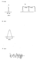
- various waveforms may be considered as the pulse wave, for example, as depicted in Fig. 2 (a)
- a triangular pulse has the temporal width of about 25 ms at the base level.
- a Hanning pulse as another example has the temporal width of about 25 ms at the base level.
- a pulse wave using this pulse is created and output similarly to the case of the triangular pulse wave.
- the control means 31 causes the air vibration pressure by an oscillation wave having only desired real-number frequency components, to be generated by giving a wave obtained by combining a plurality of sine waves at a plurality of different frequencies ( ⁇ frequency-culling 2>).
- a signal depicted in Fig. 4 that is a noise wave is output.
- a noise wave having only even-number frequency components is obtained by combining sine waves having even-number frequencies such as, for example, 2, 4, 6, ..., 34 Hz.
- a noise wave having only odd-number frequency components is obtained by combining sine waves having odd-number frequencies such as, for example, 1, 3, 5, ..., 33 Hz.
- a noise is realized by randomizing the phase of each the sine waves.
- the signal input means 35 included in the control means 31 supplies an input signal to the loudspeaker 21 such that an oscillation wave having a desired waveform is an output signal, based on reverse computing using an input signal and an output signal of the loudspeaker 21, and a transfer function of the loudspeaker 21.
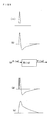
- an output signal of the loudspeaker 21 becomes a signal having a local maximum point on each of the upper and the lower sides of the zero level as depicted in Fig. 5 (b) .
- a model as depicted in Fig. 5 (c) is considered. Representing the transfer function of the loudspeaker 21 as "H( ⁇ )", the input signal thereof as "X( ⁇ )”, and the output signal thereof as "Y( ⁇ )”, the following holds and, therefore, x'(t) is obtained by reverse computation and is used as a driving signal.
- Y ⁇ X ⁇ H ⁇
- Y( ⁇ ) obtained has no component that includes frequencies up to a high frequency and, therefore, x'(t) obtained from (Equation 1) is unstable. Therefore, as expressed in (Equation 2), a term obtained by adding a constant "A 0 " to the denominator of X'( ⁇ ) is inversely Fourier-transformed and, thereby, x' (t) is obtained and is used as the driving signal.
- the signal x' (t) depicted in Fig. 5 (e) may also be obtained by reverse-computing a signal formed by adding an impulse to an onset portion as depicted in Fig. 5(d) of an output signal of the loudspeaker 21 as depicted in Fig. 5(b) .
- a signal may also be obtained by the reverse computation and this signal may also drive the loudspeaker 21.
- a signal may also be obtained by the reverse computation and a noise wave may also be obtained by this signal combining.
- an instruction may be given to the computer 30 using a keyboard, etc., not depicted and, in response to this, the control means 31 outputs a signal waveform selected thereby.
- the Fourier transforming means 32, the extracting means 33, and the computing means 34 included in the computer 30 will be described. Under the pressurized condition in the oral cavity caused by a driving of the loudspeaker 21 as above, the Fourier transforming means 32 obtains signals using the pressure sensor 12 and the flow sensor 13, Fourier-transforms these signals obtained, and obtains a spectrum.
- a CIC filter 36 is provided in the pre-stage of the Fourier transforming means 32 and separates a breathing signal and an oscillation component obtained by the pressure sensor 12 and the flow sensor 13 from each other.
- the Fourier transforming means 32 takes out a signal using a Hanning window before the processing when necessary.
- the extracting means 33 obtains a breathing high frequency component using the spectrum that corresponds to the frequency components culled from the result of the transformation by the Fourier transforming means 32, and takes out the oscillation wave component by subtracting the breathing high frequency component from the spectrum that corresponds to the frequency components left by the culling. Describing based on ⁇ frequency-culling 1>, as to the spectrum obtained by the Fourier transforming means 32, the breathing high frequency component is obtained using the spectrum that corresponds to other frequencies excluding n/T (n: an integer) frequency components, and the oscillation wave component is taken out by subtracting the breathing high frequency component from the spectrum that corresponds to the frequency components left by the culling (n/T-frequency components).
- the extracting means 33 obtains the breathing high frequency component using the spectrum that corresponds to the frequency components (odd-number frequency components or even-number frequency components) that are different from the frequency components (in this case, even-number frequency components or odd-number frequency components) given to the loudspeaker 21, and takes out the oscillation wave component by subtracting the breathing high frequency component from the spectrum that corresponds to the frequency components given to the loudspeaker 21.
- the computing means 34 calculates respiratory impedance by dividing a pressure component by a flow component for each frequency. Representing the respiratory impedance as Z( ⁇ ), an oscillation wave component of the pressure in the oral cavity as P( ⁇ ), and an oscillation wave component of the flow as F( ⁇ ) and assuming that the respiratory impedance Z( ⁇ ) includes a resistance component R( ⁇ ) and a reactance component X( ⁇ ), the respiratory impedance Z( ⁇ ) is obtained using the following equations.
- the respiratory impedance Z( ⁇ ) obtained by the computing means 34 is converted into a display signal for a displaying unit 40 such as an LCD that is connected to the computer 30 and is output to the displaying unit 40 and, thereby, display is executed.
- a displaying unit 40 such as an LCD that is connected to the computer 30 and is output to the displaying unit 40 and, thereby, display is executed.
- the triangular pulse wave is selected and a measuring operation is started.
- the loudspeaker 21 is driven with the cycle of T second (for example, at intervals of 0.5 second) by the control means 31 and the signal input means 35 using the waveform obtained by the reverse computation.
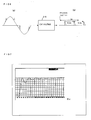
- both of the waveforms of the signals obtained by the pressure sensor 12 and the flow sensor 13 each are a waveform formed by superimposing the triangular pulse wave on the breathing signal as depicted in Fig. 6(a) .
- This waveform is passed through the CIC filter 36 and the separation of the breathing wave and the oscillation wave (the triangular pulse wave) from each other is executed.
- Fig. 7 depicts the frequency property of the CIC filter 36.
- the CIC filter 36 may execute the separation without any shift of the phase.
- the breathing signal includes a high frequency component (the same frequency band as that of the oscillation signal) and, therefore, the separation may not be completely executed.
- a section of one second is taken out at the intermediate point between two triangular pulses and is used for signal processing.
- a section of T second is taken out and a process using a Hanning window is executed for each pulse and, thereby, pulses are taken out.
- the breathing signal spectrum is obtained that includes no oscillation wave component in its spectrum of odd-number frequencies of 1, 3, 5, ... that correspond to the frequency components culled.
- the spectrum of even-number frequencies of 2, 4, 6, ... that corresponds to the frequency components left by the culling includes the oscillation wave component and the breathing signal component.
- the extracting means 33 subtracts a noise component that is estimated from the spectrum of the odd-number frequencies, from the spectrum of the even-number frequencies and, thereby, takes out the oscillation wave component.
- the computing means 34 divides the pressure component by the flow component and, thereby, calculates the respiratory impedance as expressed by Equation (2) for each frequency for the result of the extraction by the extracting means 33.
- a display signal of the respiratory impedance calculated is created and is output to the displaying unit 40 and, thereby, display is executed.
- Fig. 11 The respiratory impedance that is measured and displayed as above is depicted in Fig. 11 .
- Fig. 12 depicts the respiratory impedance obtained when the breathing high frequency the removal of the breathing high frequency signal is not executed.
- the axis of abscissa is a frequency axis whose one section of graduation corresponds to 1 Hz and the axis of ordinate represents the impedance.
- An oblique axis is the time axis.
- a genuine resistance portion is displayed in the upper portion of the diagram and a reactance portion is displayed in the lower portion of the diagram. In this case, by consecutively giving the triangular pulses at intervals of 0.5 second, display of new impedance appears one after another and the display is updated.
- the computing means 34 executes an interpolating process and, thereby, respiratory impedance measurement is enabled for the component that is not present.
- the loudspeaker 21 is driven by the control means 31 and the signal input means 35 using the noise wave having only even-number-frequency component based on the waveform obtained by the combining.
- both of the waveforms of the signals obtained by the pressure sensor 12 and the flow sensor 13 each are a waveform formed by superimposing the noise wave on the breathing signal as depicted in Fig. 13(a) .
- These signals are passed through the CIC filter 36 and, thereby, the separation of the breathing wave and the oscillation wave (noise wave) from each other is executed ( Fig. 13(b) ).
- Fig. 14 (a) After the separation by the CIC filter 36, as depicted in Fig. 14 (a) , as to the oscillation wave, a section of one second is taken out and is used for the signal processing. As depicted in Fig. 14(b) , Fourier transformation by the Fourier transforming means 32 is executed for the noise wave from which the section of one second is taken out and, thereby, the spectrum is obtained.
- the loudspeaker 21 is driven by the noise wave having only the even-number-frequency component combined by the control means 31 and the signal input means 35. Therefore, a breathing signal spectrum is obtained whose spectrum of the odd-number frequencies of 1, 3, 5, ... that corresponds to the frequency components culled does not include the oscillation wave component.
- the spectrum of the even-number frequencies of 2, 4, 6, ... that corresponds to the frequency components left by the culling includes the oscillation wave component and the breathing signal component.
- the extracting means 33 executes subtraction of the odd-number-frequency spectrum from the even-number-frequency spectrum and, thereby, takes out the oscillation wave component.
- the processes after this are same as the processes executed when the triangular pulse wave is used ( Figs. 9 and 10 and the computation using Equation (2)).
- a display signal of the respiratory impedance calculated is created and is output to the displaying unit 40, and, thereby, display is executed.
- the noise wave is used as above, the noise may also be removed and high precision respiratory impedance measurement is enabled.
- new impedance display appears one after another and, thereby, the display is updated. Thereby, continuous measurement of the impedance is executed.
- display whose noise is removed is executed similarly to the case depicted in Fig. 11 and the continuous measurement of the impedance is enabled.
- the computing means 34 creates the image to execute the display on the displaying apparatus and executes the display and, thereby, a respiratory impedance display method is realized.
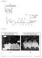
- the computing means 34 for example: determines a coordinate such that each frequency value is taken from the side distant from a viewer to the side close thereto of the image; takes out a resistance component Rrs for each frequency; plots this in the direction of the height of the screen of the displaying apparatus; takes the measurement time in the rightward direction of the screen; creates a three-dimensional image as depicted in Fig. 15 ; and displays the three-dimensional image on the displaying apparatus.
- This display is executed three-dimensionally taking values using the impedance axis, the frequency axis, and the time axis.
- an image is created and is displayed that is formed by including the respiratory impedance obtained by executing the interpolation process for the frequencies culled, in the case where values are three-dimensionally taken. For example, when the odd-number frequencies are culled, two impedance values are already obtained that correspond to even-number frequencies that are adjacent to an odd number culled. Therefore, the average of these two impedance values is obtained and is used as an impedance value that corresponds to the frequency culled. In this manner, the result of the interpolation process is also converted into an image and is displayed as the image and, therefore, variation of the impedance value may minutely and smoothly be displayed and grasp of the impedance for the whole frequencies may properly be executed.
- the sampling time is 0.5 second and, as depicted in Fig. 15(b) , the image is created and displayed taking the length in the direction of the time axis that is a length long enough to repeat therein at least two sets of exhalation and inhalation. In the example of Fig. 15 , the length is taken to be long enough to repeat therein three sets of exhalation and inhalation.
- An image is also created and displayed that expresses the magnitude of the impedance value using variation in color or variation in gradation.
- an image is created and displayed being colored for the resistance value Rrs based on the color scale presented in the lower portion of Fig. 15 .
- Images obtained by the processes are displayed and, therefore, a subject only has to repeat inhaling and exhaling and images as depicted in Fig. 15 may automatically and time-sequentially be created and displayed.
- Each of the images may visually be observed as an image that expresses the variation of the respiratory impedance using variation in color or variation in gradation, including the portions that correspond to the frequencies culled.
- %FEV1 of Fig. 15(b) is a value that indicates how many % of the forced vital capacity is exhaled in one second. Therefore, in this example, it is presented that 24.4% was able to be exhaled in one second.
Landscapes
- Health & Medical Sciences (AREA)
- Life Sciences & Earth Sciences (AREA)
- Engineering & Computer Science (AREA)
- Physics & Mathematics (AREA)
- Medical Informatics (AREA)
- Animal Behavior & Ethology (AREA)
- Pathology (AREA)
- Veterinary Medicine (AREA)
- Biomedical Technology (AREA)
- Heart & Thoracic Surgery (AREA)
- Public Health (AREA)
- Molecular Biology (AREA)
- Surgery (AREA)
- Biophysics (AREA)
- General Health & Medical Sciences (AREA)
- Pulmonology (AREA)
- Physiology (AREA)
- Mathematical Physics (AREA)
- Artificial Intelligence (AREA)
- Computer Vision & Pattern Recognition (AREA)
- Psychiatry (AREA)
- Signal Processing (AREA)
- Measurement Of The Respiration, Hearing Ability, Form, And Blood Characteristics Of Living Organisms (AREA)
Description
- The present invention relates to a respiratory impedance measuring apparatus and method that are capable of continuously measuring a respiratory impedance of a human being, etc., and to a respiratory impedance display method.
- Conventionally, an apparatus of this kind is known that includes a sine-wave pressurizing apparatus to apply as a load a sine-wave air vibration pressure to a respiratory system, an air current velocity detector to detect an air current velocity of the respiratory system, an air pressure detector to detect an air pressure of the respiratory system, and a resistance computing unit that calculates breathing resistance from the air current velocity and the air pressure detected by the air current velocity detector and the air pressure detector.
- The conventional apparatus: further includes a reference signal converter to convert a signal of the sine-wave air vibration pressure that is applied by the sine-wave pressurizing apparatus into a reference signal and a vector computing device that processes a signal of the air current velocity using the reference signal of the sine-wave air vibration pressure from the reference signal converter and that, thereby, takes out only a component at the same frequency as that of the reference signal; and is adapted to calculate the breathing resistance using the resistance computing unit from the signal of the air current velocity obtained by the vector computing device and the signal of the air pressure detected by the air pressure detector.
- As above, this apparatus is adapted to measure the breathing resistance using the resistance computing unit from the signal of the air current velocity obtained by the vector computing device and the signal of the air pressure detected by the air pressure detector and, therefore, noises may be removed even when the amount of ventilation of the breathing is a little and the number of ventilating sessions is large. Therefore the apparatus has an advantage that the apparatus may execute high precision measurement of breathing resistance (see Patent Document 1).
- The analysis of the respiratory impedance using pressure oscillations directed to the oral cavity are the subject-matters of various publications, including
US 6,142,952 A ,US 6,435,182 B1 ,US 2005/247307 A1 , LUTCHEN K R ET AL: "Use Of Transfer Impedance Measurements For Clinical Assessment of Lung Mechanics", AMERICAN JOURNAL OF RESPIRATORY AND CRITICAL CARE MEDICINE, AMERICAN LUNG ASSOCIATION, NEW YORK, NY, US, vol. 157, 1 January 1998 (1998-01-01), pages 435-446, XP003004877, ISSN: 1073-449X, IONESCU C ET AL: "Detection of novel respiratory mechanic parameters by means of forced oscillations", PROCEEDINGS OF THE WORLD CONGRESS OF IFAC, XX, XX, no. 16TH, 4 July 2005 (2005-07-04), pages 1-6, XP002604715, OOSTVEN E ET AL: "The forced oscillation technique in clinical practice: methodology, recommendations and future developments", EUROPEAN RESPIRATORY JOURNAL, MUNKSGAARD INTERNATIONAL PUBLISHERS, COPENHAGEN, DK, vol. 22, 1 January 2003 (2003-01-01), pages 1026-1041, XP002551341, ISSN: 0903-1936, DOI: 10.1183/09031936.03.00089403 - However, the removal of the noises is not sufficient even by the conventional apparatus and realization of a higher-perfomance respiratory impedance measuring apparatus is demanded.
- Patent Literature 1: Japanese Patent Application the KOKAI Publication No.
H03-039140 - The present invention was conceived in view of the current circumstances in respiratory impedance measurement and an object thereof is to provide a respiratory impedance measuring apparatus and method that are capable of continuously measuring impedance for a plurality of frequencies at one time. Another object thereof is to provide a respiratory impedance measuring apparatus and method that are capable of removing noises and measuring respiratory impedance with extremely high precision, and a respiratory impedance display method.
- The objects indicated above are achieved by a respiratory impedance measuring apparatus according to
claim 1 and a respiratory impedance measurement method according to claim 7. Further developments of the invention are given in the dependent claims. - The respiratory impedance measuring apparatus according to the present invention characteristically includes: a pressurizing means to apply an air vibration pressure to the inside of an oral cavity, a control means that causes the air vibration pressure to be generated, by an oscillation wave that is a signal to drive this pressurizing means and that is a signal obtained by frequency-culling executed such that the signal has only the frequency components that are left after the culling is executed from a plurality of different frequencies; a pressure detecting means that detects the pressure of the inside of an oral cavity; a flow detecting means that detects a flow generated by breathing; a Fourier transforming means that obtains signals obtained by the pressure detecting means and the flow detecting means under the pressurized condition provided by the pressurizing means, that Fourier-transforms the signals obtained, and that obtains a spectrum; an extracting means that obtains a breathing high frequency component based on a spectrum that corresponds to the frequency component culled from the result of the transformation by the Fourier transforming means, and that takes out an oscillation wave component by subtracting the breathing high frequency component from a spectrum that corresponds to a frequency component left by the culling; and a computing means that divides a pressure component by a flow component for each frequency for the result of the extraction by the extracting means.
- The respiratory impedance measuring apparatus according to the present invention is characterized in that the control means causes the air vibration pressure to be generated, by the oscillation wave having only n/T (n: an integer, T: a real number) frequency components, by giving a pulse wave having the cycle T as the frequency culling. Such frequency-culling is referred to as <frequency-culling 1>. In <frequency-
culling 1>, when T is determined, a plurality of frequency components are obtained that are left by culling the frequency components other than n/T (n: an integer) frequency components. - The respiratory impedance measuring apparatus according to the present invention is characterized in that the control means combines a plurality of sine waves at different frequencies, thereby, obtains an oscillation wave frequency-culled, and causes the air vibration pressure by the oscillation wave to be generated. Such frequency-culling is referred to as <frequency-culling 2>. In <frequency-
culling 2>, the signal is also enabled to have only a plurality of integer-frequency components left by culling desired integers from consecutive integers and, therefore, the signal may include a plurality of integer-frequency components left by culling odd-number frequency components. - The respiratory impedance measuring apparatus according to the present invention is characterized in that the control means includes a signal input means that supplies an input signal to the pressurizing means such that an oscillation wave having a desired pressure waveform is an output signal, based on reverse computation using the input signal and the output signal of the pressurizing means and a transfer function of the pressurizing means.
- The respiratory impedance measuring apparatus according to the present invention is characterized in that the signal input means supplies to the pressurizing means as an input signal a signal obtained by adding a specific value to each of frequency components of the signal obtained by the reverse computing, or by reverse computing the signal formed by adding an impulse to an onset portion of the output signal.
- The respiratory impedance measurement method according to the present invention characteristically includes: a pressurizing step to apply an air vibration pressure to the inside of an oral cavity; a control step of causing the air vibration pressure to be generated, by an oscillation wave that is a signal to control this pressurizing step and that is a signal obtained by frequency-culling executed such that this signal has only the frequency component that is left after the culling is executed from a plurality of different frequencies; a pressure detecting step of detecting the pressure of the inside of the oral cavity; a flow detecting step of detecting the flow generated by breathing; a Fourier-transforming step of obtaining signals obtained at the pressure detecting step and the flow detecting step under the pressurized condition provided at the pressurizing step, Fourier-transforming the signals obtained, and, thereby, obtaining a spectrum; an extracting step of obtaining a breathing high frequency component based on a spectrum that corresponds to the frequency components culled from the result of the transformation at the Fourier transforming step, and taking out an oscillation wave component by subtracting the breathing high frequency component from a spectrum that corresponds to frequency components left by the culling; and a computing step of dividing a pressure component by a flow component for each of frequencies for the result of the extraction at the extracting step, and the method is characterized in that each of the steps is executed by processing and control of a computer.
- The respiratory impedance measurement method according to the present invention is characterized in that, at the control step, the air vibration pressure is caused to be generated, by an oscillation wave having only n/T (n: an integer, T: a real number) frequency components by supplying a pulse wave having a cycle T as the frequency-culling. Such frequency-culling is <frequency-
culling 1>. - The respiratory impedance measurement method according to the present invention is characterized in that, at the control step, the air vibration pressure is caused to be generated, by an oscillation wave by obtaining the oscillation wave frequency-culled, that is obtained by combining a plurality of sine waves at a plurality of different frequencies. Such frequency-culling is <frequency-culling 2>.
- The respiratory impedance measurement method according to the present invention is characterized in that the control step includes a signal input step of supplying an input signal at the pressurizing step such that an oscillation wave having a desired pressure waveform is an output signal, based on reverse computation using the input signal and the output signal at the pressurizing step and a transfer function at the pressurizing step.
- The respiratory impedance measurement method according to the present invention is characterized in that, at the signal input step, a signal is supplied at the pressurizing step, that is obtained by adding a specific value to each of frequency components of the signal obtained by the reverse computing, or by reverse computing the signal formed by adding an impulse to an onset portion of the output signal.
- The respiratory impedance display method according to the present invention is characterized in that, in a respiratory impedance display method of executing display on a displaying apparatus based on the respiratory impedance measured by the respiratory impedance measuring apparatus: the display is executed by three-dimensionally taking values based on an impedance axis, a frequency axis, and a time axis; an image is created by including respiratory impedance obtained by executing an interpolation process for the culled frequencies, in the display to execute the display by three-dimensionally taking values; and, thereby, the display is executed.
- The respiratory impedance display method according to the present invention is characterized in that the display is executed by creating the image with the length in the direction of the time axis, that is taken to be a length enough to repeat therein at least two sets of exhalation and inhalation.
- The respiratory impedance display method according to the present invention is characterized in that the display is executed by creating an image that expresses magnitude of an impedance value using variation in color or variation in gradation.
- According to the present invention: an air vibration pressure by an oscillation wave that is frequency-culled is applied to the inside of an oral cavity; the pressure of the inside of the oral cavity is detected; the flow of breathing is detected; a spectrum is obtained by Fourier-transforming these signals obtained; a breathing high frequency component that contributes as a noise is obtained using a spectrum that corresponds to frequency components culled from the result of the Fourier transformation; the breathing high frequency component is subtracted from a spectrum that corresponds to the frequency components left by the culling; thereby, an oscillation wave component is extracted; computing is executed of dividing a pressure component by a flow component for each of frequencies for the result of this extraction; and, thereby, respiratory impedance is obtained. Therefore, the respiratory impedance may be obtained using the oscillation wave component from which the breathing high frequency component is securely removed and, therefore, impedance measurement with extremely high precision may be enabled.
- According to the present invention: the air vibration pressure by the oscillation wave having only the n/T (n: an integer, T: a real number) frequency components is caused to be generated by supplying the pulse having the cycle T; therefore, the breathing high frequency component is obtained using the spectrum that corresponds to the frequency components culled; and the breathing high frequency component is subtracted from the spectrum that corresponds to the frequency components left by the culling. Therefore, the breathing high frequency component may securely be removed and the respiratory impedance measurement with extremely high precision is enabled.
- According to the present invention, the plurality of sine waves at the plurality of different frequencies are combined and, thereby, the air vibration pressure by the oscillation wave that is frequency-component-culled is caused to be generated. Therefore, only the breathing high frequency component is included by the spectrum that corresponds to the frequency components culled and, therefore, the breathing high frequency component may securely be removed and the respiratory impedance measurement with extremely high precision is enabled.
- According to the present invention, an input signal is supplied to a pressurizing executing portion such that the oscillation wave having a desired pressure waveform is the output signal based on the reverse computation using the input signal and the output signal for the pressurizing and a transfer function of the pressurizing executing portion. Therefore, the measurement may be executed using the oscillation wave having the desired pressure waveform and respiratory impedance measurement with extremely high precision is enabled.
- According to the present invention, the input signal is the signal obtained by adding a specific value to each of the frequency components of the signal obtained by the reverse computing, or by reverse computing the signal formed by adding an impulse to the onset portion of the output signal. Therefore, the signal waveform of the result of the reverse computing may be stabilized and, thereby, the measurement using the oscillation wave having a desired waveform may be executed and the respiratory impedance measurement with extremely high precision is enabled.
- According to the respiratory impedance display method according to the present invention, in the respiratory impedance display method of executing display on a displaying apparatus based on the respiratory impedance measured by the respiratory impedance measuring apparatus: the display is executed three-dimensionally taking values based on the impedance axis, the frequency axis, and the time axis; an image is created by including the respiratory impedance obtained by executing an interpolation process for the culled frequencies, in the display to execute display three-dimensionally taking values; and, thereby, the display is executed. Therefore, the result of the interpolation process is also displayed as an image. Therefore, variation of the impedance value may minutely and smoothly be displayed and grasp of the impedance for the whole frequencies may properly be executed.
- According to the respiratory impedance display method according to the present invention, the display is executed by creating the image with the length in the direction of the time axis that is a length long enough to repeat therein at least two sets of exhalation and inhalation. Therefore, not an observation of a sudden variation but an observation having a specific span is enabled and, thereby, proper observations may be secured.
- According to the respiratory impedance display method according to the present invention, the display is executed by creating the image that expresses magnitude of an impedance value using variation in color or variation in gradation. Therefore, to obviously distinguish the magnitudes of impedance values is easily enabled and it is expected that the method is very useful for various researches and inspections that use the respiratory impedance.
- Embodiments of a respiratory impedance measuring apparatus and method according to the present invention will be described with reference to the accompanying drawings.
Fig. 1 is a diagram of the configuration of the embodiment of the respiratory impedance measuring apparatus according to the present invention. The respiratory impedance measuring apparatus includes as its main components: a tube 11 whose tip is attached to an oral cavity of a human and through which a breathing flow flows; a pressure sensor 12 that is attached to the tube 11 and that makes up a pressure detecting means to detect the pressure in the oral cavity; aflow sensor 13 that makes up a flow detecting means of detecting the flow of breathing at the same position as that of the pressure sensor 12; a loudspeaker 21 that makes up a pressurizing means to apply an air vibration pressure to the inside of the oral cavity; and acomputer 30. - An output signal of the pressure sensor 12 is amplified by an
amplifier 14, is digitized by an A/D converter 15, and is taken in by thecomputer 30. An output signal of theflow sensor 13 is amplified by anamplifier 16, is digitized by an A/D converter 17, and is taken in by thecomputer 30. - The
computer 30 includes a control means 31, a Fourier transforming means 32, an extractingmeans 33, and a computing means 34. The control means 31 includes a signal input means 35. The control means 31 outputs a signal driving the loudspeaker 21 that is the pressurizing means and causes the air vibration pressure by an oscillation wave having only odd-number frequency components or even-number frequency components, to be generated. An output of the control means 31 is converted into an analog signal by a D/A converter 22 and is sent to adriver 23. Thedriver 23 drives the loudspeaker 21 and, thereby, the air vibration pressure is applied to the inside of the oral cavity. - In the above, the control means 31 causes the air vibration pressure by the oscillation wave having n/T (n: an integer, T: a real number) frequency components, to be generated by giving a pulse wave having the cycle of T second (<frequency-culling 1>). Though various waveforms may be considered as the pulse wave, for example, as depicted in
Fig. 2 (a) , a triangular pulse has the temporal width of about 25 ms at the base level. When this triangular pulse is output with the cycle T that is, for example, T=0.5 second, a triangular pulse wave having a spectrum of 2, 4, 6, 8 Hz, ... may be given (Fig. 2(b) ). When the triangular pulse is output with the cycle T that is, for example, T=0.333 second, a triangular pulse wave having a spectrum of 3, 6, 9, 12 Hz, ... may be given. - As depicted in
Fig. 3 , a Hanning pulse as another example has the temporal width of about 25 ms at the base level. A pulse wave using this pulse is created and output similarly to the case of the triangular pulse wave. - The control means 31 causes the air vibration pressure by an oscillation wave having only desired real-number frequency components, to be generated by giving a wave obtained by combining a plurality of sine waves at a plurality of different frequencies (<frequency-culling 2>). In this case, a signal depicted in
Fig. 4 that is a noise wave is output. In this case, a noise wave having only even-number frequency components is obtained by combining sine waves having even-number frequencies such as, for example, 2, 4, 6, ..., 34 Hz. A noise wave having only odd-number frequency components is obtained by combining sine waves having odd-number frequencies such as, for example, 1, 3, 5, ..., 33 Hz. A noise is realized by randomizing the phase of each the sine waves. - The signal input means 35 included in the control means 31 supplies an input signal to the loudspeaker 21 such that an oscillation wave having a desired waveform is an output signal, based on reverse computing using an input signal and an output signal of the loudspeaker 21, and a transfer function of the loudspeaker 21.
- More specifically, describing using, for example, a triangular pulse, when the loudspeaker 21 is driven by inputting thereinto a triangular pulse as depicted in
Fig. 5 (a) , an output signal of the loudspeaker 21 becomes a signal having a local maximum point on each of the upper and the lower sides of the zero level as depicted inFig. 5 (b) . A model as depicted inFig. 5 (c) is considered. Representing the transfer function of the loudspeaker 21 as "H(ω)", the input signal thereof as "X(ω)", and the output signal thereof as "Y(ω)", the following holds and, therefore, x'(t) is obtained by reverse computation and is used as a driving signal.
- Representing an input as X'((ω)) with which X(ω) is obtained,



- Practically,

- Y(ω) obtained has no component that includes frequencies up to a high frequency and, therefore, x'(t) obtained from (Equation 1) is unstable. Therefore, as expressed in (Equation 2), a term obtained by adding a constant "A0" to the denominator of X'(ω) is inversely Fourier-transformed and, thereby, x' (t) is obtained and is used as the driving signal. The signal x' (t) depicted in
Fig. 5 (e) may also be obtained by reverse-computing a signal formed by adding an impulse to an onset portion as depicted inFig. 5(d) of an output signal of the loudspeaker 21 as depicted inFig. 5(b) . - Though the case for the triangular pulse is described in the above, as to a Hanning pulse, a signal may also be obtained by the reverse computation and this signal may also drive the loudspeaker 21. As to a sine wave, a signal may also be obtained by the reverse computation and a noise wave may also be obtained by this signal combining.
- As to which one of the pulse wave, the noise wave, and the sine wave having a single frequency is used, an instruction may be given to the
computer 30 using a keyboard, etc., not depicted and, in response to this, the control means 31 outputs a signal waveform selected thereby. - The
Fourier transforming means 32, the extractingmeans 33, and the computing means 34 included in thecomputer 30 will be described. Under the pressurized condition in the oral cavity caused by a driving of the loudspeaker 21 as above, theFourier transforming means 32 obtains signals using the pressure sensor 12 and theflow sensor 13, Fourier-transforms these signals obtained, and obtains a spectrum. ACIC filter 36 is provided in the pre-stage of theFourier transforming means 32 and separates a breathing signal and an oscillation component obtained by the pressure sensor 12 and theflow sensor 13 from each other. TheFourier transforming means 32 takes out a signal using a Hanning window before the processing when necessary. - The extracting means 33 obtains a breathing high frequency component using the spectrum that corresponds to the frequency components culled from the result of the transformation by the
Fourier transforming means 32, and takes out the oscillation wave component by subtracting the breathing high frequency component from the spectrum that corresponds to the frequency components left by the culling. Describing based on <frequency-culling 1>, as to the spectrum obtained by theFourier transforming means 32, the breathing high frequency component is obtained using the spectrum that corresponds to other frequencies excluding n/T (n: an integer) frequency components, and the oscillation wave component is taken out by subtracting the breathing high frequency component from the spectrum that corresponds to the frequency components left by the culling (n/T-frequency components). - Describing based on <frequency-culling 2>, as to the spectrum obtained by the
Fourier transforming means 32, the extractingmeans 33 obtains the breathing high frequency component using the spectrum that corresponds to the frequency components (odd-number frequency components or even-number frequency components) that are different from the frequency components (in this case, even-number frequency components or odd-number frequency components) given to the loudspeaker 21, and takes out the oscillation wave component by subtracting the breathing high frequency component from the spectrum that corresponds to the frequency components given to the loudspeaker 21. - As to the result of the extraction by the extracting
means 33, the computing means 34 calculates respiratory impedance by dividing a pressure component by a flow component for each frequency. Representing the respiratory impedance as Z(ω), an oscillation wave component of the pressure in the oral cavity as P(ω), and an oscillation wave component of the flow as F(ω) and assuming that the respiratory impedance Z(ω) includes a resistance component R(ω) and a reactance component X(ω), the respiratory impedance Z(ω) is obtained using the following equations. - [Eq. 2]

- The respiratory impedance Z(ω) obtained by the computing means 34 is converted into a display signal for a displaying unit 40 such as an LCD that is connected to the
computer 30 and is output to the displaying unit 40 and, thereby, display is executed. - Operations by the respiratory impedance measuring apparatus configured as above will be described. In this example, the triangular pulse wave is selected and a measuring operation is started. The loudspeaker 21 is driven with the cycle of T second (for example, at intervals of 0.5 second) by the control means 31 and the signal input means 35 using the waveform obtained by the reverse computation.
- At this time, both of the waveforms of the signals obtained by the pressure sensor 12 and the
flow sensor 13 each are a waveform formed by superimposing the triangular pulse wave on the breathing signal as depicted inFig. 6(a) . This waveform is passed through theCIC filter 36 and the separation of the breathing wave and the oscillation wave (the triangular pulse wave) from each other is executed.Fig. 7 depicts the frequency property of theCIC filter 36. TheCIC filter 36 may execute the separation without any shift of the phase. However, the breathing signal includes a high frequency component (the same frequency band as that of the oscillation signal) and, therefore, the separation may not be completely executed. - After the separation by the
CIC filter 36, as depicted inFig. 6 (b) , as to the oscillation wave, a section of one second is taken out at the intermediate point between two triangular pulses and is used for signal processing. As depicted inFig. 8 , a section of T second is taken out and a process using a Hanning window is executed for each pulse and, thereby, pulses are taken out. - Following the process using the Hanning window, Fourier transformation by the
Fourier transforming means 32 is executed and a spectrum is obtained. At this time, as to the spectrum obtained, for example, when a pulse is driven with the cycle of 0.5 second, as depicted inFig. 9 , the breathing signal spectrum is obtained that includes no oscillation wave component in its spectrum of odd-number frequencies of 1, 3, 5, ... that correspond to the frequency components culled. The spectrum of even-number frequencies of 2, 4, 6, ... that corresponds to the frequency components left by the culling includes the oscillation wave component and the breathing signal component. - As depicted in
Fig. 10 , the extractingmeans 33 subtracts a noise component that is estimated from the spectrum of the odd-number frequencies, from the spectrum of the even-number frequencies and, thereby, takes out the oscillation wave component. - The breathing high frequency signal that is equal to or higher than 3 Hz and that is conventionally considered not to be included in the breathing signal, is removed by the processing of the extracting
means 33 and, therefore, high precision respiratory impedance measurement is enabled. The computing means 34 divides the pressure component by the flow component and, thereby, calculates the respiratory impedance as expressed by Equation (2) for each frequency for the result of the extraction by the extractingmeans 33. A display signal of the respiratory impedance calculated is created and is output to the displaying unit 40 and, thereby, display is executed. - The respiratory impedance that is measured and displayed as above is depicted in
Fig. 11 .Fig. 12 depicts the respiratory impedance obtained when the breathing high frequency the removal of the breathing high frequency signal is not executed. In each ofFigs. 11 and12 , the axis of abscissa is a frequency axis whose one section of graduation corresponds to 1 Hz and the axis of ordinate represents the impedance. An oblique axis is the time axis. A genuine resistance portion is displayed in the upper portion of the diagram and a reactance portion is displayed in the lower portion of the diagram. In this case, by consecutively giving the triangular pulses at intervals of 0.5 second, display of new impedance appears one after another and the display is updated. Thereby, continuous measurement of the impedance is executed. As apparently seen fromFigs. 11 and12 , it is understood that the noise is removed and high precision respiratory impedance measurement is enabled. As apparent from the subtracting process by the extractingmeans 33, the component left by the subtraction is the even-number-frequency component of 2, 4, 6, ... that corresponds to the frequency component left by the culling and, the odd-number-frequency component of 1, 3, 5, ... that corresponds to the frequency component culled is not present. The computing means 34 executes an interpolating process and, thereby, respiratory impedance measurement is enabled for the component that is not present. - The case where the noise wave is selected instead of the triangular pulse wave and the measuring operation is started (<frequency-culling 2>) will be described. The loudspeaker 21 is driven by the control means 31 and the signal input means 35 using the noise wave having only even-number-frequency component based on the waveform obtained by the combining. At this time, both of the waveforms of the signals obtained by the pressure sensor 12 and the
flow sensor 13 each are a waveform formed by superimposing the noise wave on the breathing signal as depicted inFig. 13(a) . These signals are passed through theCIC filter 36 and, thereby, the separation of the breathing wave and the oscillation wave (noise wave) from each other is executed (Fig. 13(b) ). - After the separation by the
CIC filter 36, as depicted inFig. 14 (a) , as to the oscillation wave, a section of one second is taken out and is used for the signal processing. As depicted inFig. 14(b) , Fourier transformation by theFourier transforming means 32 is executed for the noise wave from which the section of one second is taken out and, thereby, the spectrum is obtained. - As to the spectrum obtained by the Fourier transformation, the loudspeaker 21 is driven by the noise wave having only the even-number-frequency component combined by the control means 31 and the signal input means 35. Therefore, a breathing signal spectrum is obtained whose spectrum of the odd-number frequencies of 1, 3, 5, ... that corresponds to the frequency components culled does not include the oscillation wave component. The spectrum of the even-number frequencies of 2, 4, 6, ... that corresponds to the frequency components left by the culling includes the oscillation wave component and the breathing signal component.
- The extracting means 33 executes subtraction of the odd-number-frequency spectrum from the even-number-frequency spectrum and, thereby, takes out the oscillation wave component. The processes after this are same as the processes executed when the triangular pulse wave is used (
Figs. 9 and10 and the computation using Equation (2)). A display signal of the respiratory impedance calculated is created and is output to the displaying unit 40, and, thereby, display is executed. When the noise wave is used as above, the noise may also be removed and high precision respiratory impedance measurement is enabled. By continuously giving the noise wave, new impedance display appears one after another and, thereby, the display is updated. Thereby, continuous measurement of the impedance is executed. When the noise wave is used, display whose noise is removed is executed similarly to the case depicted inFig. 11 and the continuous measurement of the impedance is enabled. - In the embodiment of the present invention, the computing means 34 creates the image to execute the display on the displaying apparatus and executes the display and, thereby, a respiratory impedance display method is realized. As to the respiratory impedance calculated by the computing means 34, the computing means 34, for example: determines a coordinate such that each frequency value is taken from the side distant from a viewer to the side close thereto of the image; takes out a resistance component Rrs for each frequency; plots this in the direction of the height of the screen of the displaying apparatus; takes the measurement time in the rightward direction of the screen; creates a three-dimensional image as depicted in
Fig. 15 ; and displays the three-dimensional image on the displaying apparatus. This display is executed three-dimensionally taking values using the impedance axis, the frequency axis, and the time axis. - For creating the image, an image is created and is displayed that is formed by including the respiratory impedance obtained by executing the interpolation process for the frequencies culled, in the case where values are three-dimensionally taken. For example, when the odd-number frequencies are culled, two impedance values are already obtained that correspond to even-number frequencies that are adjacent to an odd number culled. Therefore, the average of these two impedance values is obtained and is used as an impedance value that corresponds to the frequency culled. In this manner, the result of the interpolation process is also converted into an image and is displayed as the image and, therefore, variation of the impedance value may minutely and smoothly be displayed and grasp of the impedance for the whole frequencies may properly be executed.
- The sampling time is 0.5 second and, as depicted in
Fig. 15(b) , the image is created and displayed taking the length in the direction of the time axis that is a length long enough to repeat therein at least two sets of exhalation and inhalation. In the example ofFig. 15 , the length is taken to be long enough to repeat therein three sets of exhalation and inhalation. - An image is also created and displayed that expresses the magnitude of the impedance value using variation in color or variation in gradation. In
Fig. 15 , an image is created and displayed being colored for the resistance value Rrs based on the color scale presented in the lower portion ofFig. 15 . - Images obtained by the processes are displayed and, therefore, a subject only has to repeat inhaling and exhaling and images as depicted in
Fig. 15 may automatically and time-sequentially be created and displayed. Each of the images may visually be observed as an image that expresses the variation of the respiratory impedance using variation in color or variation in gradation, including the portions that correspond to the frequencies culled. - Therefore, as apparently seen from the variation of the respiratory impedance of a 66-year-old healthy person depicted in
Fig. 15(a) and the variation of the respiratory impedance of a 65-year-old COPD (chronic obstructive pulmonary disease) patient depicted inFig. 15(b) , to visually and obviously distinguish a non-healthy person and a healthy person from each other is easily enabled and it is expected that the method is very useful for various researches and inspections that use respiratory impedance. "%FEV1" ofFig. 15(b) is a value that indicates how many % of the forced vital capacity is exhaled in one second. Therefore, in this example, it is presented that 24.4% was able to be exhaled in one second. -
- [
Fig. 1] Fig. 1 is a diagram of the configuration of a respiratory impedance measuring apparatus according to an embodiment of the present invention. - [
Fig. 2] Fig. 2 is a diagram of an example of a triangular pulse wave that is an oscillation wave used in the respiratory impedance measuring apparatus according to the embodiment of the present invention. - [
Fig. 3] Fig. 3 is a diagram of an example of a Hanning pulse wave that is an oscillation wave used in the respiratory impedance measuring apparatus according to the embodiment of the present invention. - [
Fig. 4] Fig. 4 is a diagram of an example of a noise wave that is an oscillation wave used in the respiratory impedance measuring apparatus according to the embodiment of the present invention. - [
Fig. 5] Fig. 5 is a diagram for explaining the process of creating, using reverse computation, the oscillation wave used in the respiratory impedance measuring apparatus according to the embodiment of the present invention. - [
Fig. 6] Fig. 6 is a diagram of a process of obtaining the respiratory impedance using the triangular pulse wave that is the oscillation wave by the respiratory impedance measuring apparatus according to the embodiment of the present invention. - [
Fig. 7] Fig. 7 is a diagram of the frequency property of a filter employed in the respiratory impedance measuring apparatus according to the embodiment of the present invention. - [
Fig. 8] Fig. 8 is a diagram of a process of obtaining the respiratory impedance using the triangular pulse wave that is the oscillation wave by the respiratory impedance measuring apparatus according to the embodiment of the present invention. - [
Fig. 9] Fig. 9 is a diagram of a process of obtaining the respiratory impedance using the triangular pulse wave that is the oscillation wave by the respiratory impedance measuring apparatus according to the embodiment of the present invention. - [
Fig. 10] Fig. 10 is a diagram of a process of obtaining the respiratory impedance using the triangular pulse wave that is the oscillation wave by the respiratory impedance measuring apparatus according to the embodiment of the present invention. - [
Fig. 11] Fig. 11 is a diagram of the respiratory impedance obtained by the respiratory impedance measuring apparatus according to the embodiment of the present invention. - [
Fig. 12] Fig. 12 is a diagram of respiratory impedance obtained by a respiratory impedance measuring apparatus that does not use the approach of the present invention. - [
Fig. 13] Fig. 13 is a diagram of a process of obtaining the respiratory impedance using a noise wave that is the oscillation wave by the respiratory impedance measuring apparatus according to the embodiment of the present invention. - [
Fig. 14] Fig. 14 is a diagram of a process of obtaining the respiratory impedance using a noise wave that is the oscillation wave by the respiratory impedance measuring apparatus according to the embodiment of the present invention. - [
Fig. 15] Fig. 15 is a diagram of an example of respiratory impedance for each of a healthy person and a non-healthy person displayed using the respiratory impedance measuring apparatus according to the embodiment of the present invention. Explanations of Letters or Numerals -
- 11
- tube
- 12
- pressure sensor
- 13
- flow sensor
- 21
- loudspeaker
- 30
- computer
- 31
- control means
- 32
- Fourier transforming means
- 33
- extracting means
- 34
- computing means
- 35
- signal input means
- 36
- CIC filter
- 40
- displaying unit
Claims (14)
- A respiratory impedance measuring apparatus comprising:a pressurizing means (21) that is configured to apply an air vibration pressure to an inside of an oral cavity;a control means (30) that is configured to cause the air vibration pressure to be generated by an oscillation wave, wherein the oscillation wave is a signal that drives the pressurizing means (21);a pressure detecting means (12) that is configured to detect a pressure of the inside of the oral cavity;a flow detecting means (13) that is configured to detect a flow generated by breathing;a Fourier transforming means (32) that is configured to obtain and Fourier-transform signals obtained by the pressure detecting means (12) and the flow detecting means (13) under a pressurized condition provided by the pressurizing means (21), thereby obtaining as a result a pressure spectrum for the signal obtained by the pressure detecting means (12) and a flow spectrum for the signal obtained by the flow detecting means (13);an extracting means (33); anda computing means (34) that is configured to divide a pressure oscillation wave component by a flow oscillation wave component; characterised in that :the oscillation wave is obtained by frequency-culling, and the frequency-culling is configured such that the signal has only those frequency components from a plurality of different frequencies that are left after the culling is executed; and;the extracting means is configured to obtain, for each of the pressure spectrum and the flow spectrum, a breathing high frequency component based on those frequency components of the pressure spectrum and the flow spectrum, respectively, that were culled during the frequency-culling,to obtain a culled pressure spectrum and a culled flow spectrum, each comprising frequency components of the pressure spectrum and the flow spectrum, respectively, that were left by the frequency-culling, andto extract pressure oscillation wave components and flow oscillation wave components by subtracting the breathing high frequency component from the culled pressure spectrum and the culled flow spectrum, respectively; and the division of a pressure oscillation wave component by a flow oscillation wave component is performed for each frequency that was left by the frequency-culling.
- The respiratory impedance measuring apparatus of claim 1, wherein
the control means (31) is configured to cause the air vibration pressure by the oscillation wave, which has only n/T (n: an integer, T: a real number) frequency components to be generated by a pulse series having a cycle T to provide for the frequency-culling. - The respiratory impedance measuring apparatus of claim 1, wherein
the control means (31) is configured to cause the air vibration pressure by the oscillation wave to be generated by obtaining the oscillation wave that is frequency-culled by combining a plurality of sine waves at a plurality of different frequencies. - The respiratory impedance measuring apparatus of any one of claims 1 to 3, wherein
the control means (31) comprises a signal input means (35) that is configured to supply an input signal to the pressurizing means (21) such that an oscillation wave having a desired pressure waveform is an output signal, and wherein the input signal is based on reverse computation using an input signal and an output signal of the pressurizing means and a transfer function of the pressurizing means. - The respiratory impedance measuring apparatus of claim 4, wherein
the signal input means (35) is configured to supply to the pressurizing means (21) as an input signal a signal obtained by adding a specific value to each frequency component of the signal obtained by the reverse computing, or by reverse computing the signal formed by adding an impulse to an onset portion of the output signal. - The respiratory impedance measuring apparatus of any one of the preceding claims, wherein
the Fourier-transforming means (32) comprises a CIC filter (36) configured to separate prior the Fourier-transforming a breathing signal and an oscillation component for each of the signals obtained by the pressure detecting means (12) and the flow detecting means (13) and
the pressure spectrum and the flow spectrum are obtained based on the respective oscillation component. - A respiratory impedance measurement method comprising:a pressurizing step to apply an air vibration pressure to an inside of an oral cavity;a control step of causing the air vibration pressure to be generated by an oscillation wave, wherein the oscillation wave is a signal that controls the pressurizing step;a pressure detecting step of detecting a pressure of the inside of the oral cavity;a flow detecting step of detecting the flow generated by breathing;a Fourier-transforming step of obtaining and Fourier-transforming signals obtained at the pressure detecting step and the flow detecting step under the pressurized condition provided at the pressurizing step, thereby, obtaining as a result a pressure spectrum for the signal obtained by the pressure detecting step and a flow spectrum for the signal obtained by the flow detecting step; anda computing step of dividing a pressure oscillation wave component by a flow oscillation wave component;
whereineach of the steps is executed by processing and control
of a computer, characterised in that the oscillation wave is obtained by frequency-culling, and the frequency-culling is executed such that the signal has only those frequency components from a plurality of different frequencies that are left after the culling is executed;, and that the method further comprisesan extracting step of
obtaining, for each of the pressure spectrum and the flow spectrum, a breathing high frequency component based those frequency components of the pressure spectrum and the flow spectrum, respectively, that were culled during the frequency-culling,
obtaining a culled pressure spectrum and a culled flow spectrum, each comprising frequency components of the pressure spectrum and the flow spectrum, respectively, that were left by the frequency-culling, and
extracting pressure oscillation wave components and flow oscillation wave components by subtracting the breathing high frequency component from culled pressure spectrum and the culled flow spectrum, respectively; and, that the computing step of dividing is performed for each frequency that was left by the frequency-culling. - The respiratory impedance measurement method of claim 7, wherein
at the control step, the air vibration pressure by an oscillation wave, which has only n/T (n: an integer, T: a real number) frequency components is caused to be generated by supplying a pulse having a cycle T to provide for the frequency-culling. - The respiratory impedance measurement method of claim 7, wherein
at the control step, the air vibration pressure by an oscillation wave is caused to be generated by obtaining the oscillation wave, which is frequency-culled, by combining a plurality of sine waves at a plurality of different frequencies. - The respiratory impedance measurement method of any one of claims 7 to 9, wherein
the control step comprises a signal input step of supplying an input signal at the pressurizing step such that an oscillation wave having a desired pressure waveform is an output signal, and wherein the input signal is based on reverse computation using an input signal and an output signal at the pressurizing step and a transfer function at the pressurizing step. - The respiratory impedance measurement method of claim 10, wherein
at the signal input step, a signal is supplied at the pressurizing step, that is obtained by adding a specific value to each frequency component of the signal obtained by the reverse computing, or by reverse computing the signal formed by adding an impulse to an onset portion of the output signal. - A respiratory impedance display method of executing display on a displaying apparatus based on respiratory impedance measured by a respiratory impedance measuring apparatus, the method comprising:performing the method of any one of claims 7 to 11, thereby measuring an respiratory impedance, whereinthe display is executed by three-dimensionally taking values based on an impedance axis, a frequency axis, and a time axis, and whereinan image is created by including respiratory impedance obtained by executing an interpolation process for culled frequencies, in an image to execute the display by three-dimensionally taking values and, thereby, the display is executed.
- The respiratory impedance display method of claim 12, wherein
the display is executed by creating an image with the length in the direction of the time axis, that is taken to be a length enough to repeat therein at least two sets of exhalation and inhalation. - The respiratory impedance display method of claim 12 or 13, wherein
the display is executed by creating an image that expresses magnitude of an impedance value using variation in color or variation in gradation.
Applications Claiming Priority (3)
| Application Number | Priority Date | Filing Date | Title |
|---|---|---|---|
| JP2008060002 | 2008-03-10 | ||
| JP2008160042A JP5198162B2 (en) | 2008-03-10 | 2008-06-19 | Respiratory impedance measuring device and measuring method thereof |
| PCT/JP2009/054441 WO2009113500A1 (en) | 2008-03-10 | 2009-03-09 | Respiration impedance measuring device and method, and respiration impedance display method |
Publications (3)
| Publication Number | Publication Date |
|---|---|
| EP2253268A1 EP2253268A1 (en) | 2010-11-24 |
| EP2253268A4 EP2253268A4 (en) | 2012-06-06 |
| EP2253268B1 true EP2253268B1 (en) | 2014-08-27 |
Family
ID=41065167
Family Applications (1)
| Application Number | Title | Priority Date | Filing Date |
|---|---|---|---|
| EP09719205.8A Active EP2253268B1 (en) | 2008-03-10 | 2009-03-09 | Respiration impedance measuring device and method, and respiration impedance display method |
Country Status (7)
| Country | Link |
|---|---|
| US (1) | US20110060237A1 (en) |
| EP (1) | EP2253268B1 (en) |
| JP (1) | JP5198162B2 (en) |
| KR (1) | KR101184657B1 (en) |
| CN (1) | CN101959455B (en) |
| CA (1) | CA2717318C (en) |
| WO (1) | WO2009113500A1 (en) |
Families Citing this family (28)
| Publication number | Priority date | Publication date | Assignee | Title |
|---|---|---|---|---|
| JP5583454B2 (en) * | 2009-04-13 | 2014-09-03 | チェスト株式会社 | Respiratory impedance measuring device and respiratory impedance display method |
| US9649050B2 (en) | 2009-12-03 | 2017-05-16 | Koninklijke Philips N.V. | Method and apparatus for estimating respiratory impedance |
| EP2384697A1 (en) * | 2010-05-05 | 2011-11-09 | Universiteit Gent | Method and device for determining non-linear effects in the respiratory impedance |
| AU2011289159C1 (en) * | 2010-08-13 | 2015-12-10 | Respiratory Motion, Inc. | Devices and methods for respiratory variation monitoring by measurement of respiratory volumes, motion and variability |
| US11723542B2 (en) | 2010-08-13 | 2023-08-15 | Respiratory Motion, Inc. | Advanced respiratory monitor and system |
| US10702166B1 (en) | 2010-08-13 | 2020-07-07 | Respiratory Motion, Inc. | Devices and methods for respiratory variation monitoring by measurement of respiratory volumes, motion and variability |
| CN102488521A (en) * | 2011-12-09 | 2012-06-13 | 东莞理工学院 | Calculation device for respiratory resistance value of medical respiratory monitor |
| US12343130B2 (en) | 2012-09-07 | 2025-07-01 | Respiratory Motion, Inc. | Spacing of electrodes for bioimpedance measurements |
| CA2883623C (en) | 2012-09-07 | 2020-06-23 | Respiratory Motion, Inc. | Electrode padset |
| US9955918B2 (en) * | 2012-12-31 | 2018-05-01 | University of Alaska Anchorage | Mouth guard for determining physiological conditions of a subject and systems and methods for using same |
| US10028679B2 (en) | 2012-12-31 | 2018-07-24 | University of Alaska Anchorage | Devices, systems, and methods for determining linear and angular accelerations of the head |
| CN103285479B (en) * | 2013-06-08 | 2015-05-06 | 首都医科大学附属北京朝阳医院 | Device for monitoring airway collapse characteristic parameters of breathing machine |
| EP3114672B1 (en) | 2014-03-06 | 2020-06-24 | Respiratory Motion, Inc. | Methods and devices for displaying trend and variability in a physiological dataset |
| WO2016073604A1 (en) | 2014-11-04 | 2016-05-12 | Respiratory Motion, Inc. | Respiratory parameter guided automated iv administration and iv tube clamp activation |
| CN104473647A (en) * | 2014-12-12 | 2015-04-01 | 温州医科大学 | Wireless forced oscillation pulmonary impedance tester and testing method thereof |
| WO2017106500A1 (en) | 2015-12-15 | 2017-06-22 | Respiratory Motion, Inc. | Evaluation of respiratory volume monitoring to detect respiratory compromise before pulse oximetry and eliminate false desaturation alarms |
| WO2017136639A1 (en) * | 2016-02-03 | 2017-08-10 | Cognita Labs, LLC | Forced oscillation technique based lung function testing |
| CN106073783B (en) * | 2016-06-23 | 2024-02-20 | 桂林航天工业学院 | A method for extracting respiratory rate from photoplethysm pulse wave |
| CN108652632B (en) * | 2017-03-31 | 2023-07-14 | 中国人民解放军总医院 | Forced oscillation pulmonary function test device and method |
| US11433202B2 (en) | 2017-12-18 | 2022-09-06 | Koninklijke Philips N.V. | Interactive guidance related to a subject's expiratory flow limitation results |
| US11395899B2 (en) * | 2018-07-05 | 2022-07-26 | Hill-Rom Services Pte. Ltd. | Apparatus and method to assess airway clearance therapy efficacy |
| JP7045073B2 (en) * | 2019-02-15 | 2022-03-31 | チェスト株式会社 | Respiratory resistance measuring device and display control method |
| JP7054929B2 (en) * | 2019-02-15 | 2022-04-15 | チェスト株式会社 | Respiratory resistance measuring device and test result prediction method |
| US12605122B2 (en) | 2019-06-07 | 2026-04-21 | Respiratory Motion, Inc. | Device and method for clinical evaluation |
| DE102020118529A1 (en) * | 2020-07-14 | 2022-01-20 | Ventinova Technologies B.V. | Ventilation device and method for determining at least one alveolar pressure or a course of an alveolar pressure in a patient's airway |
| CN115702786B (en) * | 2021-08-11 | 2026-01-13 | 深圳市美好创亿医疗科技股份有限公司 | Respiratory impedance detection method and detection system |
| CN119212615A (en) * | 2022-07-12 | 2024-12-27 | 深圳麦科田生物医疗技术股份有限公司 | Respiratory impedance measurement system and respiratory impedance measurement method |
| CN120884277B (en) * | 2025-10-09 | 2025-11-28 | 中国科学院合肥物质科学研究院 | Respiratory power detection method and system based on respiratory impedance model |
Family Cites Families (8)
| Publication number | Priority date | Publication date | Assignee | Title |
|---|---|---|---|---|
| JPS4934185A (en) * | 1972-07-31 | 1974-03-29 | ||
| JP2776900B2 (en) | 1989-07-06 | 1998-07-16 | チェスト株式会社 | Respiratory resistance measurement device |
| US6142952A (en) * | 1997-10-29 | 2000-11-07 | The Board Of Regents, The University Of Texas System | Method and apparatus for detection and diagnosis of airway obstruction degree |
| US6435182B1 (en) * | 1999-03-24 | 2002-08-20 | Trustees Of Boston University | Enhanced ventilation waveform device |
| US6443907B1 (en) * | 2000-10-06 | 2002-09-03 | Biomedical Acoustic Research, Inc. | Acoustic detection of respiratory conditions |
| AU2005237191A1 (en) * | 2004-05-04 | 2005-11-10 | Dalhousie University | Method of assessment of airway variability in airway hyperresponsiveness |
| AU2007291951B2 (en) * | 2006-08-30 | 2013-06-06 | ResMed Pty Ltd | Distinguishing closed and open respiratory airway apneas by complex admittance values |
| US8100836B2 (en) * | 2006-12-06 | 2012-01-24 | Texas Christian University | Augmented RIC model of respiratory systems |
-
2008
- 2008-06-19 JP JP2008160042A patent/JP5198162B2/en active Active
-
2009
- 2009-03-09 US US12/922,024 patent/US20110060237A1/en not_active Abandoned
- 2009-03-09 KR KR1020107020093A patent/KR101184657B1/en not_active Expired - Fee Related
- 2009-03-09 WO PCT/JP2009/054441 patent/WO2009113500A1/en not_active Ceased
- 2009-03-09 EP EP09719205.8A patent/EP2253268B1/en active Active
- 2009-03-09 CN CN200980108179XA patent/CN101959455B/en active Active
- 2009-03-09 CA CA2717318A patent/CA2717318C/en active Active
Also Published As
| Publication number | Publication date |
|---|---|
| JP2009240752A (en) | 2009-10-22 |
| JP5198162B2 (en) | 2013-05-15 |
| US20110060237A1 (en) | 2011-03-10 |
| CN101959455B (en) | 2013-03-13 |
| EP2253268A4 (en) | 2012-06-06 |
| WO2009113500A1 (en) | 2009-09-17 |
| CA2717318A1 (en) | 2009-09-17 |
| CA2717318C (en) | 2015-04-21 |
| KR101184657B1 (en) | 2012-09-20 |
| CN101959455A (en) | 2011-01-26 |
| KR20100120204A (en) | 2010-11-12 |
| EP2253268A1 (en) | 2010-11-24 |
Similar Documents
| Publication | Publication Date | Title |
|---|---|---|
| EP2253268A1 (en) | Respiration impedance measuring device and method, and respiration impedance display method | |
| US9022947B2 (en) | Respiration impedance measuring device and respiration impedance display method | |
| EP2818106B1 (en) | Apparatus for determining respiratory condition | |
| EP2247233B1 (en) | A method, apparatus and computer program product for detecting heart rate | |
| EP2737848B1 (en) | Method for enhancing accuracy of recognizing fetus heart rate acceleration data | |
| US20030130588A1 (en) | Method and system for analyzing respiratory tract sounds | |
| US6542836B1 (en) | Waveform signal analyzer | |
| US11246526B2 (en) | Swallowing diagnosis apparatus and storage medium | |
| CN108135511B (en) | Diagnosis support device, diagnosis support method, and recording medium | |
| RU2091057C1 (en) | Method of continuous check psychophysiological state of operator in process of moving object control and system intended for its realization | |
| EP3459452B1 (en) | Respiration waveform drawing system and biological information monitoring system | |
| EP3459451B1 (en) | Respiration waveform drawing system and respiration waveform drawing method | |
| EP3459450B1 (en) | Respiration waveform drawing system | |
| JP5798226B2 (en) | Pulse wave analyzer | |
| CN120570616A (en) | Fatigue assessment method and device based on cardiac autonomic nervous system dynamics and brain coupling analysis | |
| JP2014147486A (en) | Blood pressure measuring device | |
| JP5616253B2 (en) | Pulse wave analyzer | |
| CN112971765A (en) | Portable breathing motion real-time monitoring device and method | |
| WO2016139802A1 (en) | Shunt murmur analysis device, shunt murmur analysis method, computer program, and recording medium | |
| JP7001806B2 (en) | Respiratory sound analyzer, breath sound analysis method, computer program and recording medium | |
| JP2014045792A (en) | Respiration signal estimation device and respiration signal estimation method | |
| JP2019010529A (en) | Shunt murmur analyzing device | |
| JP3037266B2 (en) | Non-invasive continuous blood pressure monitor |
Legal Events
| Date | Code | Title | Description |
|---|---|---|---|
| PUAI | Public reference made under article 153(3) epc to a published international application that has entered the european phase |
Free format text: ORIGINAL CODE: 0009012 |
|
| 17P | Request for examination filed |
Effective date: 20100913 |
|
| AK | Designated contracting states |
Kind code of ref document: A1 Designated state(s): AT BE BG CH CY CZ DE DK EE ES FI FR GB GR HR HU IE IS IT LI LT LU LV MC MK MT NL NO PL PT RO SE SI SK TR |
|
| AX | Request for extension of the european patent |
Extension state: AL BA RS |
|
| DAX | Request for extension of the european patent (deleted) | ||
| A4 | Supplementary search report drawn up and despatched |
Effective date: 20120509 |
|
| RIC1 | Information provided on ipc code assigned before grant |
Ipc: A61B 5/085 20060101AFI20120503BHEP Ipc: A61B 5/08 20060101ALI20120503BHEP Ipc: A61B 10/00 20060101ALI20120503BHEP |
|
| 17Q | First examination report despatched |
Effective date: 20130104 |
|
| GRAP | Despatch of communication of intention to grant a patent |
Free format text: ORIGINAL CODE: EPIDOSNIGR1 |
|
| INTG | Intention to grant announced |
Effective date: 20140509 |
|
| GRAS | Grant fee paid |
Free format text: ORIGINAL CODE: EPIDOSNIGR3 |
|
| GRAA | (expected) grant |
Free format text: ORIGINAL CODE: 0009210 |
|
| AK | Designated contracting states |
Kind code of ref document: B1 Designated state(s): AT BE BG CH CY CZ DE DK EE ES FI FR GB GR HR HU IE IS IT LI LT LU LV MC MK MT NL NO PL PT RO SE SI SK TR |
|
| REG | Reference to a national code |
Ref country code: GB Ref legal event code: FG4D |
|
| REG | Reference to a national code |
Ref country code: CH Ref legal event code: EP |
|
| REG | Reference to a national code |
Ref country code: AT Ref legal event code: REF Ref document number: 684095 Country of ref document: AT Kind code of ref document: T Effective date: 20140915 |
|
| REG | Reference to a national code |
Ref country code: IE Ref legal event code: FG4D |
|
| REG | Reference to a national code |
Ref country code: DE Ref legal event code: R096 Ref document number: 602009026277 Country of ref document: DE Effective date: 20141009 |
|
| REG | Reference to a national code |
Ref country code: AT Ref legal event code: MK05 Ref document number: 684095 Country of ref document: AT Kind code of ref document: T Effective date: 20140827 |
|
| REG | Reference to a national code |
Ref country code: LT Ref legal event code: MG4D |
|
| REG | Reference to a national code |
Ref country code: NL Ref legal event code: VDEP Effective date: 20140827 |
|
| PG25 | Lapsed in a contracting state [announced via postgrant information from national office to epo] |
Ref country code: ES Free format text: LAPSE BECAUSE OF FAILURE TO SUBMIT A TRANSLATION OF THE DESCRIPTION OR TO PAY THE FEE WITHIN THE PRESCRIBED TIME-LIMIT Effective date: 20140827 Ref country code: PT Free format text: LAPSE BECAUSE OF FAILURE TO SUBMIT A TRANSLATION OF THE DESCRIPTION OR TO PAY THE FEE WITHIN THE PRESCRIBED TIME-LIMIT Effective date: 20141229 Ref country code: LT Free format text: LAPSE BECAUSE OF FAILURE TO SUBMIT A TRANSLATION OF THE DESCRIPTION OR TO PAY THE FEE WITHIN THE PRESCRIBED TIME-LIMIT Effective date: 20140827 Ref country code: FI Free format text: LAPSE BECAUSE OF FAILURE TO SUBMIT A TRANSLATION OF THE DESCRIPTION OR TO PAY THE FEE WITHIN THE PRESCRIBED TIME-LIMIT Effective date: 20140827 Ref country code: GR Free format text: LAPSE BECAUSE OF FAILURE TO SUBMIT A TRANSLATION OF THE DESCRIPTION OR TO PAY THE FEE WITHIN THE PRESCRIBED TIME-LIMIT Effective date: 20141128 Ref country code: NO Free format text: LAPSE BECAUSE OF FAILURE TO SUBMIT A TRANSLATION OF THE DESCRIPTION OR TO PAY THE FEE WITHIN THE PRESCRIBED TIME-LIMIT Effective date: 20141127 Ref country code: SE Free format text: LAPSE BECAUSE OF FAILURE TO SUBMIT A TRANSLATION OF THE DESCRIPTION OR TO PAY THE FEE WITHIN THE PRESCRIBED TIME-LIMIT Effective date: 20140827 Ref country code: BG Free format text: LAPSE BECAUSE OF FAILURE TO SUBMIT A TRANSLATION OF THE DESCRIPTION OR TO PAY THE FEE WITHIN THE PRESCRIBED TIME-LIMIT Effective date: 20141127 |
|
| PG25 | Lapsed in a contracting state [announced via postgrant information from national office to epo] |
Ref country code: CY Free format text: LAPSE BECAUSE OF FAILURE TO SUBMIT A TRANSLATION OF THE DESCRIPTION OR TO PAY THE FEE WITHIN THE PRESCRIBED TIME-LIMIT Effective date: 20140827 Ref country code: AT Free format text: LAPSE BECAUSE OF FAILURE TO SUBMIT A TRANSLATION OF THE DESCRIPTION OR TO PAY THE FEE WITHIN THE PRESCRIBED TIME-LIMIT Effective date: 20140827 Ref country code: HR Free format text: LAPSE BECAUSE OF FAILURE TO SUBMIT A TRANSLATION OF THE DESCRIPTION OR TO PAY THE FEE WITHIN THE PRESCRIBED TIME-LIMIT Effective date: 20140827 Ref country code: LV Free format text: LAPSE BECAUSE OF FAILURE TO SUBMIT A TRANSLATION OF THE DESCRIPTION OR TO PAY THE FEE WITHIN THE PRESCRIBED TIME-LIMIT Effective date: 20140827 Ref country code: IS Free format text: LAPSE BECAUSE OF FAILURE TO SUBMIT A TRANSLATION OF THE DESCRIPTION OR TO PAY THE FEE WITHIN THE PRESCRIBED TIME-LIMIT Effective date: 20141227 |
|
| PG25 | Lapsed in a contracting state [announced via postgrant information from national office to epo] |
Ref country code: NL Free format text: LAPSE BECAUSE OF FAILURE TO SUBMIT A TRANSLATION OF THE DESCRIPTION OR TO PAY THE FEE WITHIN THE PRESCRIBED TIME-LIMIT Effective date: 20140827 |
|
| PG25 | Lapsed in a contracting state [announced via postgrant information from national office to epo] |
Ref country code: EE Free format text: LAPSE BECAUSE OF FAILURE TO SUBMIT A TRANSLATION OF THE DESCRIPTION OR TO PAY THE FEE WITHIN THE PRESCRIBED TIME-LIMIT Effective date: 20140827 Ref country code: RO Free format text: LAPSE BECAUSE OF FAILURE TO SUBMIT A TRANSLATION OF THE DESCRIPTION OR TO PAY THE FEE WITHIN THE PRESCRIBED TIME-LIMIT Effective date: 20140827 Ref country code: SK Free format text: LAPSE BECAUSE OF FAILURE TO SUBMIT A TRANSLATION OF THE DESCRIPTION OR TO PAY THE FEE WITHIN THE PRESCRIBED TIME-LIMIT Effective date: 20140827 Ref country code: DK Free format text: LAPSE BECAUSE OF FAILURE TO SUBMIT A TRANSLATION OF THE DESCRIPTION OR TO PAY THE FEE WITHIN THE PRESCRIBED TIME-LIMIT Effective date: 20140827 Ref country code: CZ Free format text: LAPSE BECAUSE OF FAILURE TO SUBMIT A TRANSLATION OF THE DESCRIPTION OR TO PAY THE FEE WITHIN THE PRESCRIBED TIME-LIMIT Effective date: 20140827 Ref country code: IT Free format text: LAPSE BECAUSE OF FAILURE TO SUBMIT A TRANSLATION OF THE DESCRIPTION OR TO PAY THE FEE WITHIN THE PRESCRIBED TIME-LIMIT Effective date: 20140827 |
|
| REG | Reference to a national code |
Ref country code: DE Ref legal event code: R097 Ref document number: 602009026277 Country of ref document: DE |
|
| PG25 | Lapsed in a contracting state [announced via postgrant information from national office to epo] |
Ref country code: PL Free format text: LAPSE BECAUSE OF FAILURE TO SUBMIT A TRANSLATION OF THE DESCRIPTION OR TO PAY THE FEE WITHIN THE PRESCRIBED TIME-LIMIT Effective date: 20140827 |
|
| PLBE | No opposition filed within time limit |
Free format text: ORIGINAL CODE: 0009261 |
|
| STAA | Information on the status of an ep patent application or granted ep patent |
Free format text: STATUS: NO OPPOSITION FILED WITHIN TIME LIMIT |
|
| 26N | No opposition filed |
Effective date: 20150528 |
|
| PG25 | Lapsed in a contracting state [announced via postgrant information from national office to epo] |
Ref country code: LU Free format text: LAPSE BECAUSE OF FAILURE TO SUBMIT A TRANSLATION OF THE DESCRIPTION OR TO PAY THE FEE WITHIN THE PRESCRIBED TIME-LIMIT Effective date: 20150309 Ref country code: MC Free format text: LAPSE BECAUSE OF FAILURE TO SUBMIT A TRANSLATION OF THE DESCRIPTION OR TO PAY THE FEE WITHIN THE PRESCRIBED TIME-LIMIT Effective date: 20140827 |
|
| REG | Reference to a national code |
Ref country code: CH Ref legal event code: PL |
|
| PG25 | Lapsed in a contracting state [announced via postgrant information from national office to epo] |
Ref country code: SI Free format text: LAPSE BECAUSE OF FAILURE TO SUBMIT A TRANSLATION OF THE DESCRIPTION OR TO PAY THE FEE WITHIN THE PRESCRIBED TIME-LIMIT Effective date: 20140827 |
|
| REG | Reference to a national code |
Ref country code: IE Ref legal event code: MM4A |
|
| PG25 | Lapsed in a contracting state [announced via postgrant information from national office to epo] |
Ref country code: LI Free format text: LAPSE BECAUSE OF NON-PAYMENT OF DUE FEES Effective date: 20150331 Ref country code: CH Free format text: LAPSE BECAUSE OF NON-PAYMENT OF DUE FEES Effective date: 20150331 Ref country code: IE Free format text: LAPSE BECAUSE OF NON-PAYMENT OF DUE FEES Effective date: 20150309 |
|
| REG | Reference to a national code |
Ref country code: FR Ref legal event code: PLFP Year of fee payment: 8 |
|
| PG25 | Lapsed in a contracting state [announced via postgrant information from national office to epo] |
Ref country code: BE Free format text: LAPSE BECAUSE OF FAILURE TO SUBMIT A TRANSLATION OF THE DESCRIPTION OR TO PAY THE FEE WITHIN THE PRESCRIBED TIME-LIMIT Effective date: 20140827 |
|
| PG25 | Lapsed in a contracting state [announced via postgrant information from national office to epo] |
Ref country code: MT Free format text: LAPSE BECAUSE OF FAILURE TO SUBMIT A TRANSLATION OF THE DESCRIPTION OR TO PAY THE FEE WITHIN THE PRESCRIBED TIME-LIMIT Effective date: 20140827 |
|
| REG | Reference to a national code |
Ref country code: FR Ref legal event code: PLFP Year of fee payment: 9 |
|
| PG25 | Lapsed in a contracting state [announced via postgrant information from national office to epo] |
Ref country code: HU Free format text: LAPSE BECAUSE OF FAILURE TO SUBMIT A TRANSLATION OF THE DESCRIPTION OR TO PAY THE FEE WITHIN THE PRESCRIBED TIME-LIMIT; INVALID AB INITIO Effective date: 20090309 |
|
| PG25 | Lapsed in a contracting state [announced via postgrant information from national office to epo] |
Ref country code: TR Free format text: LAPSE BECAUSE OF FAILURE TO SUBMIT A TRANSLATION OF THE DESCRIPTION OR TO PAY THE FEE WITHIN THE PRESCRIBED TIME-LIMIT Effective date: 20140827 |
|
| REG | Reference to a national code |
Ref country code: FR Ref legal event code: PLFP Year of fee payment: 10 |
|
| PG25 | Lapsed in a contracting state [announced via postgrant information from national office to epo] |
Ref country code: MK Free format text: LAPSE BECAUSE OF FAILURE TO SUBMIT A TRANSLATION OF THE DESCRIPTION OR TO PAY THE FEE WITHIN THE PRESCRIBED TIME-LIMIT Effective date: 20140827 |
|
| PGFP | Annual fee paid to national office [announced via postgrant information from national office to epo] |
Ref country code: GB Payment date: 20220324 Year of fee payment: 14 |
|
| PGFP | Annual fee paid to national office [announced via postgrant information from national office to epo] |
Ref country code: FR Payment date: 20220323 Year of fee payment: 14 |
|
| GBPC | Gb: european patent ceased through non-payment of renewal fee |
Effective date: 20230309 |
|
| PG25 | Lapsed in a contracting state [announced via postgrant information from national office to epo] |
Ref country code: GB Free format text: LAPSE BECAUSE OF NON-PAYMENT OF DUE FEES Effective date: 20230309 |
|
| PG25 | Lapsed in a contracting state [announced via postgrant information from national office to epo] |
Ref country code: GB Free format text: LAPSE BECAUSE OF NON-PAYMENT OF DUE FEES Effective date: 20230309 Ref country code: FR Free format text: LAPSE BECAUSE OF NON-PAYMENT OF DUE FEES Effective date: 20230331 |
|
| PGFP | Annual fee paid to national office [announced via postgrant information from national office to epo] |
Ref country code: DE Payment date: 20250324 Year of fee payment: 17 |