EP2252543B1 - Water dispenser with a reservoir system and faucet manifold therefor - Google Patents
Water dispenser with a reservoir system and faucet manifold therefor Download PDFInfo
- Publication number
- EP2252543B1 EP2252543B1 EP09707079.1A EP09707079A EP2252543B1 EP 2252543 B1 EP2252543 B1 EP 2252543B1 EP 09707079 A EP09707079 A EP 09707079A EP 2252543 B1 EP2252543 B1 EP 2252543B1
- Authority
- EP
- European Patent Office
- Prior art keywords
- water
- reservoir
- faucet
- treatment apparatus
- dispenser
- Prior art date
- Legal status (The legal status is an assumption and is not a legal conclusion. Google has not performed a legal analysis and makes no representation as to the accuracy of the status listed.)
- Active
Links
- XLYOFNOQVPJJNP-UHFFFAOYSA-N water Substances O XLYOFNOQVPJJNP-UHFFFAOYSA-N 0.000 title claims description 306
- 238000004891 communication Methods 0.000 claims description 20
- 239000012530 fluid Substances 0.000 claims description 19
- 230000005484 gravity Effects 0.000 claims description 13
- 239000007788 liquid Substances 0.000 description 7
- 238000010438 heat treatment Methods 0.000 description 3
- 238000000034 method Methods 0.000 description 3
- 238000005057 refrigeration Methods 0.000 description 3
- 238000001816 cooling Methods 0.000 description 2
- 235000011389 fruit/vegetable juice Nutrition 0.000 description 2
- 238000009413 insulation Methods 0.000 description 2
- 235000014214 soft drink Nutrition 0.000 description 2
- XUIMIQQOPSSXEZ-UHFFFAOYSA-N Silicon Chemical group [Si] XUIMIQQOPSSXEZ-UHFFFAOYSA-N 0.000 description 1
- 241001122767 Theaceae Species 0.000 description 1
- 230000000712 assembly Effects 0.000 description 1
- 238000000429 assembly Methods 0.000 description 1
- 235000013361 beverage Nutrition 0.000 description 1
- 238000010276 construction Methods 0.000 description 1
- 239000011521 glass Substances 0.000 description 1
- 235000020278 hot chocolate Nutrition 0.000 description 1
- 235000021539 instant coffee Nutrition 0.000 description 1
- 239000000203 mixture Substances 0.000 description 1
- 239000003507 refrigerant Substances 0.000 description 1
- 230000000630 rising effect Effects 0.000 description 1
- 235000013616 tea Nutrition 0.000 description 1
- 239000003643 water by type Substances 0.000 description 1
Images




Classifications
-
- B—PERFORMING OPERATIONS; TRANSPORTING
- B67—OPENING, CLOSING OR CLEANING BOTTLES, JARS OR SIMILAR CONTAINERS; LIQUID HANDLING
- B67D—DISPENSING, DELIVERING OR TRANSFERRING LIQUIDS, NOT OTHERWISE PROVIDED FOR
- B67D3/00—Apparatus or devices for controlling flow of liquids under gravity from storage containers for dispensing purposes
- B67D3/0009—Apparatus or devices for controlling flow of liquids under gravity from storage containers for dispensing purposes provided with cooling arrangements
-
- B—PERFORMING OPERATIONS; TRANSPORTING
- B67—OPENING, CLOSING OR CLEANING BOTTLES, JARS OR SIMILAR CONTAINERS; LIQUID HANDLING
- B67D—DISPENSING, DELIVERING OR TRANSFERRING LIQUIDS, NOT OTHERWISE PROVIDED FOR
- B67D3/00—Apparatus or devices for controlling flow of liquids under gravity from storage containers for dispensing purposes
- B67D3/0022—Apparatus or devices for controlling flow of liquids under gravity from storage containers for dispensing purposes provided with heating arrangements
-
- B—PERFORMING OPERATIONS; TRANSPORTING
- B67—OPENING, CLOSING OR CLEANING BOTTLES, JARS OR SIMILAR CONTAINERS; LIQUID HANDLING
- B67D—DISPENSING, DELIVERING OR TRANSFERRING LIQUIDS, NOT OTHERWISE PROVIDED FOR
- B67D3/00—Apparatus or devices for controlling flow of liquids under gravity from storage containers for dispensing purposes
- B67D3/0029—Apparatus or devices for controlling flow of liquids under gravity from storage containers for dispensing purposes provided with holders for bottles or similar containers
-
- B—PERFORMING OPERATIONS; TRANSPORTING
- B67—OPENING, CLOSING OR CLEANING BOTTLES, JARS OR SIMILAR CONTAINERS; LIQUID HANDLING
- B67D—DISPENSING, DELIVERING OR TRANSFERRING LIQUIDS, NOT OTHERWISE PROVIDED FOR
- B67D3/00—Apparatus or devices for controlling flow of liquids under gravity from storage containers for dispensing purposes
- B67D3/0038—Apparatus or devices for controlling flow of liquids under gravity from storage containers for dispensing purposes the liquid being stored in an intermediate container prior to dispensing
Definitions
- Liquid or water dispensers including water coolers are well known devices that cool and dispense water.
- Free-standing water coolers include bottles of water placed spout-down into a reservoir within the dispensing machine housing. The water in the reservoir is accessed via a faucet.
- These devices include faucets for dispensing water in a controlled manner. These devices come in a variety of sizes and vary from table units, intended for occasional use to floor-mounted units intended for heavier use. Some units offer a refrigeration function to chill the water. Usually, these units do not have a place to dump excess water, only offering a small basin to catch minor spills.
- Some versions also have a second dispenser that delivers heated water that can be used for tea, hot chocolate, or instant coffee.
- a water dispenser comprising:
- a reservoir longitudinally extending within the housing and defining top and bottom ends thereof, the reservoir top end being in fluid communication with the water bottle so as to receive water therefrom thereby filling the reservoir;
- faucet-reservoir assembly for a water dispenser, the faucet-reservoir assembly comprising:
- each valve mounted between the main body and the dispensing outlet, each valve providing access to water within a respective one of the compartments;
- At least one additional outlet for being mounted to an auxiliary longitudinal conduit being in fluid communication with a water treatment apparatus
- a water delivery system or dispenser comprising a reservoir, a water bottle receiving assembly and a faucet manifold.
- Figure 9 is a front elevation view of the faucet-reservoir assembly of Figure 8 ;
- Figure 12 is the view of Figure 11 including a schematic water bottle in stippled line;
- Ambient water W-a flows downwardly by gravity into the faucet manifold 30 from the water bottle 12 via the baffle 28 and short conduit 32.
- the cold W-c flows from the reservoir 26 to the faucet manifold 30 via the feed tube 34 when there is a suitable pressure on the water W in the reservoir about section 66.
- Hot water W-h flows from the hot tank 62 into the faucet manifold 30 via the return conduit 64 when there is a suitable pressure on the water W in the reservoir about section 66.
- Figure 3 shows a faucet manifold 300 having a main body 302.
- Three valves 304, 306 and 308 respectively control the flow of water from three compartments 310, 312 and 314 towards the exit compartment 316.
- Compartment 310 is defined by inner walls 318 and 320, exit compartment wall 322 and the main body 302.
- Compartment 312 is defined by inner walls 318, 320 and 324, exit compartment wall 322 and the main body 302.
- Compartment 314 is defined by inner wall 324, exit compartment wall 322 and the main body 302.
- a fourth compartment 326 which is not in communication with a valve is defined by the main body 302 and inner walls 318 and 324.
- Ambient water in compartment 326 flows towards a hot tank via inlet 332 for heating thereof and hot water flows into compartment 310 via outlet 334.
- Ambient water in compartment 326 also enters inlet 336 where it is brought to another apparatus, such as a carbonator for example, to then flow upwardly (similarly to the process explained above for hot water W-h) as carbonated water into compartment 312 via outlet 338.
- compartment 310 is filled with hot water
- compartment 312 is filled with carbonated water
- compartment 314 is filled with cold water all of which are accessible by respectively opening valves 304, 306 and 308.
- Ambient water within compartment 516 flows downwardly to the hot tank via inlet 534 to upwardly return as hot water into compartment 514 via outlet 536.
- Cold water within compartment 520 flows downwardly to another apparatus (such as carbonating unit or filter) via inlet 538 for carbonation or other treatment thereof and upwardly returns as cold carbonated or otherwise treated water into compartment 518 via outlet 540.
- compartment 514 is filled with hot water
- compartment 516 is filled with ambient water
- compartment 518 is filled with cold carbonated or otherwise treated water
- compartment 520 is filled with cold water which can be selectively accessed by the user by respectively opening valves 504, 506, 508 and 510.
- FIGS 8 to 14 show a faucet-reservoir assembly 100 for a water dispenser (not shown)
Landscapes
- Engineering & Computer Science (AREA)
- Mechanical Engineering (AREA)
- Devices For Dispensing Beverages (AREA)
Description
- The present invention relates to a liquid dispenser. More specifically, the present invention relates to a water dispenser with a reservoir system and faucet manifold therefor.
- Liquid or water dispensers including water coolers are well known devices that cool and dispense water. Free-standing water coolers include bottles of water placed spout-down into a reservoir within the dispensing machine housing. The water in the reservoir is accessed via a faucet. These devices include faucets for dispensing water in a controlled manner. These devices come in a variety of sizes and vary from table units, intended for occasional use to floor-mounted units intended for heavier use. Some units offer a refrigeration function to chill the water. Usually, these units do not have a place to dump excess water, only offering a small basin to catch minor spills. Some versions also have a second dispenser that delivers heated water that can be used for tea, hot chocolate, or instant coffee.
- A drawback of conventional water dispensers is that the faucet is placed too low along the body of the dispensing machine, whereas providing reservoirs that are higher up creates tall and unstable units. Furthermore, in certain markets there are requirements to sanitize water dispensers. This process is often lengthy and difficult. In addition, hands may touch parts of components that are in contact with water. In this process it often results in recontamination of these parts.
For example,US 5 979 709 A describes an apparatus for the dispensing of liquids, the apparatus comprising the features of the preamble ofclaim 1. - An object of the present invention is to provide a water dispenser
- Further described is a faucet-reservoir assembly for a water dispenser.
- Further described is a faucet device for a water dispenser.
- In accordance with an aspect of the present invention, there is provided a water dispenser comprising:
- a housing comprising a top portion thereof for receiving a water bottle spout-down;
- a reservoir longitudinally extending within the housing and defining top and bottom ends thereof, the reservoir top end being in fluid communication with the water bottle so as to receive water therefrom thereby filling the reservoir;
- a faucet mounted to the housing and being positioned closer to the reservoir top end than to the reservoir bottom end;
- a longitudinal conduit in fluid communication at a top end thereof with the faucet and having a bottom end thereof extending to the reservoir bottom end and defining an inlet, and an auxiliary longitudinal conduit extending from said faucet towards a water treatment apparatus, a return longitudinal conduit extending from said water treatment apparatus to said faucet,
- wherein water flows from the water bottle into the reservoir via gravity, the water flow pressure causing water to enter the inlet and flow upwardly the longitudinal conduit to be accessed via the faucet, and wherein water flows downwardly via gravity from said faucet to said water treatment apparatus, the water flow pressure from said auxiliary longitudinal conduit causing water in said water treatment apparatus to flow upwardly into said return longitudinal conduit to be accessed via said faucet.
- Further described is a faucet-reservoir assembly for a water dispenser, the faucet-reservoir assembly comprising:
- a reservoir comprising a top section thereof defining a top end for receiving a water bottle spout-down and a longitudinally extending bottom section defining a bottom end;
- a faucet mounted to the reservoir at a position that is closer to the reservoir top end than to the reservoir bottom end;
- a longitudinal conduit in fluid communication at a top end thereof with the faucet and having a bottom end thereof extending to the reservoir bottom end and defining an inlet,
- wherein water flows from the water bottle into the reservoir via gravity, the water flow pressure causing water to enter the inlet and flow upwardly the longitudinal conduit to be accessed via the faucet.
- In an embodiment of the present invention, there is provided a water dispenser comprising:
- a housing having a top opening and a lateral opening;
- a reservoir being removably mountable to the housing via the top opening and comprising a longitudinally extending reservoir bottom section defining a bottom end and a reservoir top section extending therefrom for receiving a water bottle spout-down, a longitudinal conduit extending at one end thereof from a reservoir opening along the reservoir into the bottom section and defining a conduit inlet at an opposite end thereof; and
- a faucet being removably mountable to the reservoir about the housing lateral opening and comprising a faucet inlet for being aligned with the reservoir opening.
- Further described is a faucet-reservoir assembly for being mounted to a water dispenser having a housing with a top opening and a lateral opening, the faucet-reservoir assembly comprising:
- a reservoir being removably mountable to the housing via the top opening and comprising a longitudinally extending reservoir bottom section defining a bottom end and a reservoir top section extending therefrom for receiving a water bottle spout-down, a longitudinal conduit extending at one end thereof from a reservoir opening along the reservoir into the bottom section and defining a conduit inlet at an opposite end thereof; and
- a faucet being removably mountable to the reservoir about the housing lateral opening and comprising a faucet inlet for being aligned with the reservoir opening.
- Further described is a faucet device for being mounted to a water dispenser having a reservoir, the faucet device comprising:
- an inlet for being in fluid communication with the reservoir via a conduit;
- an outlet for dispensing water;
- at least one additional outlet for being mountable to an auxiliary conduit extending from a treatment apparatus; and
- at least one additional inlet for being mountable to a return longitudinal conduit in extending from the water treatment apparatus.
- Further described is a faucet device for a water dispenser, the faucet device comprising:
- a main body for containing water therein;
- at least two water inlets for providing water to the main body from a reservoir in the water dispenser;
- a dispensing outlet for drawing water from the main body;
- at least three compartments formed within the main body;
- at least two valves mounted between the main body and the dispensing outlet, each valve providing access to water within a respective one of the compartments;
- at least one additional outlet in a given compartment; and
- at least one additional inlet in a a compartment other than the given compartment.
- In an illustrative embodiment, there is provided a water dispenser comprising an auxiliary longitudinal conduit extending from the faucet towards a water treatment apparatus, a return longitudinal conduit extending from the water treatment apparatus to the faucet, wherein water flows downwardly via gravity from said faucet to the water treatment apparatus, the water flow pressure from the auxiliary longitudinal conduit causing water in the water treatment apparatus to flow upwardly into the return longitudinal conduit to be accessed via the faucet. In an illustrative embodiment, there is provided a water dispenser comprising at least one additional auxiliary longitudinal conduit extending from the faucet towards at least one additional water treatment apparatus, at least one additional return longitudinal conduit extending from the additional water treatment apparatus to the faucet, wherein water flows downwardly via gravity from the faucet to the additional water treatment apparatus, the water flow pressure from the additional auxiliary longitudinal conduit causing water in the additional water treatment apparatus to flow upwardly into the additional return longitudinal conduit to be accessed via said faucet.
Further embodiments of the invention are defined by the appended claims. - In an illustrative embodiment, the faucet comprises:
- an inlet for being in fluid communication with the longitudinal conduit for receiving water therefrom;
- an outlet for dispensing water;
- at least one additional outlet for being mounted to an auxiliary longitudinal conduit being in fluid communication with a water treatment apparatus; and
- at least one additional inlet for being mounted to a return longitudinal conduit in fluid communication with the water treatment apparatus,
- wherein water flows downwardly via gravity from the faucet to the water treatment apparatus, the water flow pressure from the auxiliary longitudinal conduit causing water in the water treatment apparatus to flow upwardly into the return longitudinal conduit to be accessed via said faucet.
- In an illustrative embodiment, the faucet comprises at least two valves, wherein one of the valves provides for accessing water from the reservoir bottom section and the other of the valves provides for accessing water other than water from the water reservoir bottom section.
- In an illustrative embodiment, the faucet comprises:
- an outlet for dispensing water;
- at least one additional outlet for being mounted to an auxiliary longitudinal conduit extending from a treatment apparatus within the waters dispenser housing; and
- at least one additional inlet for being mounted to a return longitudinal conduit extending from the water treatment apparatus.
- In an illustrative embodiment, there is provided a water dispenser comprising: a housing configured to allow water to flow therein from a water bottle mounted thereto; a longitudinal reservoir defining top and bottom ends thereof and being so mounted to the housing as to extend therein and as to be placed in fluid communication with the water bottle mounted to the housing; and a faucet in fluid communication with the reservoir and mounted to the housing at a longitudinal position that is closer to the top end of the reservoir than the bottom end thereof.
- In an illustrative embodiment, there is provided a water dispenser comprising: a housing configured to allow water to flow therein from a water bottle mounted thereto; a longitudinal reservoir defining top and bottom ends thereof and being so mounted to the housing as to extend therein and as to be placed in fluid communication with the water bottle mounted to the housing, the longitudinal top end receiving water, a conduit extending from the top end to about the bottom end and having a bottom opening for receiving water therein; and a faucet in fluid communication with a top opening of the conduit.
- In an illustrative embodiment, there is provided a faucet-reservoir assembly for being mounted to a water dispenser, the assembly comprising: a water receiving portion configured to allow water to flow therein from a water bottle mounted thereto; a longitudinal reservoir extending from the water receiving portion and defining an opposite bottom end thereof; and a faucet in fluid communication with the reservoir and being so mountable along the dispenser as to be as to be positioned at longitudinal position that is closer to the water receiving portion that the reservoir bottom end.
- In an illustrative embodiment, there is provided a faucet-reservoir assembly for being mounted to a water dispenser, the assembly comprising: a water receiving portion configured to allow water to flow therein from a water bottle mounted thereto; a longitudinal reservoir extending from the water receiving portion and defining an opposite bottom end thereof, a conduit extending inside the reservoir from the top end thereof to about the bottom end and having a bottom opening for receiving water therein; and a faucet in fluid communication with a top opening of the conduit.
- In an illustrative embodiment, there is provided a faucet device such as a faucet manifold for a water dispenser comprising: at least one water entry, though usually two water entries, a diverting section including compartments, inlets and outlets; a dispensing outlet; and valves so as to release water from a given compartment thereof.
- In illustrative embodiment, there is provided a reservoir system for a water dispenser that requires the faucet to be higher than the bottom of the reservoir. Hence, water is drawn through a feed tube that extends between the bottom of the reservoir and the faucet for dispensing thereof.
- In an illustrative embodiment, there is provided a faucet device such as a faucet manifold for a water dispenser which provides to redirect water to one or more of variety of apparatuses such as a hot tank system or carbonator for sparkling beverages to give but two non-limiting examples.
- In an illustrative embodiment, there is provided a water delivery system or dispenser comprising a reservoir, a water bottle receiving assembly and a faucet manifold.
- In an illustrative embodiment, there is provided a water dispenser provided for its reservoir to be removed, without tools, in an upward motion. The reservoir is held into place by a lid and/or ring mechanism. A baffle separates the room temperature water or ambient temperature from cold water. A variety of faucet devices such as faucet manifolds can separate and divert or redirect water within the water dispenser so as to provide cold water only, room temperature (ambient) water and cold temperature, hot and cold water or any combination thereof to give but a few non-limiting examples. The connection between the faucet manifold and the reservoir may be by pressure fittings, slide connection, key connection, tube connection or other means. The faucet manifolds includes one or more valves that can be opened and closed to deliver water. In an illustrative embodiment, the faucet manifold can be clipped on to, or attached by any other means to secure it to the chassis or reservoir or both. In an alternative embodiment, the system may have a pump, turbine and/or air pressure.
- The terms "faucet" and "faucet device" are used herein interchangeably. The terms "opening", "inlet" or "outlet" may also be interchangeably. These terms are used for indicative purposes within the context of the text. In essence, outlets and inlets are opening and an outlet from a first component to a second component is also an inlet for the second component and vice versa. The terms "auxiliary" and "additional" are used herein only as indications of the amount of a given element or component.
- It should be noted that a water dispenser is also a liquid dispenser and as such the invention is not limited to only water but can be used with other liquids such as juices or soft drinks for example.
- Other objects, advantages and features of the present invention will become more apparent upon reading of the following non-restrictive description of non-limiting illustrative embodiments thereof, given by way of example only with reference to the accompanying drawings.
- In the appended drawings, like reference numerals denote like elements throughout, where:
-
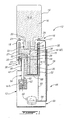
Figure 1 is a schematic view of a water dispenser in accordance with a non-restrictive illustrative embodiment of the present invention; -
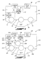
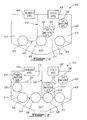
Figures 2 to 7 are schematic views of respective non-restrictive illustrative embodiments of the faucet of the present invention; -
Figure 8 is a perspective view of the faucet-reservoir assembly in accordance with a non-restrictive illustrative embodiment of the invention; -
Figure 9 is a front elevation view of the faucet-reservoir assembly ofFigure 8 ; -
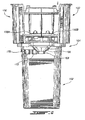
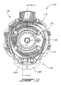
Figure 10 is a top view of the faucet-reservoir assembly ofFigure 8 ; -
Figure 11 is a side sectional view along the line Z-Z ofFigure 10 ; -
Figure 12 is the view ofFigure 11 including a schematic water bottle in stippled line; -
Figure 13 is a partial and broken disassembled perspective view of the faucet-reservoir assembly ofFigure 8 ; and -
Figure 14 is a top view of the faucet mounted to the top section of the reservoir in accordance with a non-restrictive illustrative embodiment of the invention. - A first non-restrictive illustrative embodiment of the invention will be described with reference to schematic
Figure 1 so as to present the general features thereof. -
Figure 1 shows awater dispenser 10 comprising a main body orhousing 12 and aremovable water bottle 14 containing water W. - The
housing 12 includes an upperwater dispenser cabinet 15 with atop portion 16 defining an open top end for receiving thewater bottle 14 in an inverted or spout-down position. More specifically, thetop portion 16 includes awater inlet 18 which mates with thespout 20 of thewater bottle 14. Thewater bottle 14 is held in place within anopening 22 defined bywater bottle receptacle 17 at thetop portion 16 thereby providing a space for thespout 20. - The
housing 12 includes areservoir 25 having atop section 66 thereof being in fluid communication with theinlet 18 and a contiguous bottom reservoir section orbasin 26 longitudinally extending within thehousing 12. Aring member 24 secures thereservoir 25 in place and serves to receive thewater bottle 14 in place. Since thewater bottle 14 is in an inverted position, the water W contained therein will flow downwardly by gravity into thereservoir 25. Thereservoir 25 is enveloped byinsulation 27. A separator or baffle 28 is interposed between theinlet 18 and thereservoir basin 26 so as to direct a portion of the water W flowing from the water bottle towards afaucet 30 such as a faucet manifold (of course other faucet devices may be used) via ashort conduit 32. A conduit such as afeed tube 34 extends from thefaucet manifold 30 deep into thereservoir basin 26. - As is shown in the drawings the
reservoir bottom section 26 is longer and narrower than thetop section 66 and the faucet manifold is mounted about a junction between the top andbottom sections 66 and.26 respectively. - The
housing 12 provides a lateral opening in the form of a front recessedportion 36 defining aninward back wall 38 interposed between top andbottom shoulders portion 36 provides a water exit space, with theoutlet 44 of thefaucet manifold 30 being positioned at thetop shoulder 40 and thebottom shoulder 42 defining a cup or glass holder. Of course, the skilled artisan will easily contemplate of variety of configurations for the facade of thewater dispenser 10 and as such a variety of lateral openings. - The
water dispenser 10 includes arefrigeration system 46 comprising acooling compressor 48 positioned within thehousing 12 and linked, via asuction tube connection 50 that allows refrigerant to flow back to the compressor, to achiller coil 52 surrounding thereservoir basin 26. Thecompressor 46 is also linked, via a tube connection 54 to acondenser 56 mounted on theback side 58 of thehousing 12. Of course, the skilled artisan can contemplate a variety of configurations for cooling the water in the reservoir as is well known in the art. - A
long conduit 60 extends from thefaucet manifold 30 to ahot tank 62 positioned deep within thehousing 12 beneath thereservoir 25 so as to lead water W thereto. Along return conduit 64 extends from thehot tank 62 to thefaucet manifold 30, leading hot water thereto. - In operation, water W flows from the
water bottle 14 via thespout 20 andinlet 18 into thebaffle 28 where it is lead to thereservoir basin 26 viapassage 29 so as to fill up thereservoir 25. In other cases, water overflows from thebaffle 28 and flows to thereservoir basin 26. As water W continues to flow into thereservoir basin 26 it feeds into thefeed tube 34 leading to thefaucet manifold 30. Water from thefaucet manifold 30 flows downwardly by gravity intoconduit 60 thereby filling up thehot tank 62 and rising upwardly, due to the pressure of constant incoming water W, into thereturn conduit 64 and back to thefaucet manifold 30. - The water W in the
water bottle 14, generally denoted by reference W-a, is ambient water since it is generally at room temperature. The water W in thereservoir basin 26, generally denoted here by reference W-c, since it is cooled down or chilled by therefrigeration system 46. The water at thetop section 66 of thereservoir 25, generally demoted W-a/c, can be a mixture of ambient and cold water. The water W from the hot tank, generally denoted by reference W-h, is hot water. - Ambient water W-a flows downwardly by gravity into the
faucet manifold 30 from thewater bottle 12 via thebaffle 28 andshort conduit 32. The cold W-c flows from thereservoir 26 to thefaucet manifold 30 via thefeed tube 34 when there is a suitable pressure on the water W in the reservoir aboutsection 66. Hot water W-h flows from thehot tank 62 into thefaucet manifold 30 via thereturn conduit 64 when there is a suitable pressure on the water W in the reservoir aboutsection 66. - The foregoing configuration provides for positioning the
faucet manifold 30 at a higher level along thehousing 12 which is basically above the position of the bottom 68 of thereservoir basin 26. - As will be explained below, a user can select between ambient (W-a), cold (W-c) or hot (W-h) water W via the
faucet manifold 30. -
Figure 2 is a schematic drawing of thefaucet manifold 30. - The
faucet manifold 30 includes amain body 70. Threevalves compartments exit compartment 84 which leads to the water outlet 44 (seeFigure 1 ). Thevalves Compartment 78 is defined byinner wall 79,exit compartment wall 85 and themain body 70.Compartment 80 is defined byinner walls exit compartment wall 85 and themain body 70.Compartment 82 is defined byinner wall 81,exit compartment wall 85 and themain body 70. - The
main body 70 includes an external surrounding wall as well as a floor and a ceiling. - In one non-restrictive embodiment, the separator walls are formed of doubled walls, i.e. a pair of adjacent wall segments spaced apart to contain air therebetween which acts as insulation thereby avoiding that the temperature of a given compartment affects the other adjacent compartment.
- Ambient water W-a enters
compartment 80 via anambient water entry 86 whereas cold water W-c enterscompartment 82 via acold water entry 88. The ambient water W-a incompartment 80 flows downwardly by gravity viainlet 90 towards thehot water tank 62 where it is heated and then flows upwardly as hot water W-h therefrom intocompartment 78 viaoutlet 92. In this way,compartment 78 is filled with hot water W-h,compartment 80 is filled with ambient water W-a andcompartment 82 is filled with cold water W-c. As such, the user can access hot water W-h, by openingvalve 72, ambient water W-a by openingvalve 74 and cold water W-c by openingvalve 76. - With reference to
Figures 3 to 7 , various non-restrictive illustrative embodiments of alternative faucet devices such as faucet manifolds within the context of the present invention will now be described so as to further exemplify the present invention and by no means limit the scope thereof. -
Figure 3 shows afaucet manifold 300 having amain body 302. Threevalves compartments exit compartment 316.Compartment 310 is defined byinner walls exit compartment wall 322 and themain body 302.Compartment 312 is defined byinner walls exit compartment wall 322 and themain body 302.Compartment 314 is defined byinner wall 324,exit compartment wall 322 and themain body 302. A fourth compartment 326 which is not in communication with a valve is defined by themain body 302 andinner walls - Ambient water enters compartment 326 via an
ambient water entry 328, whereas cold water enterscompartment 314 via acold water entry 330. Ambient water in compartment 326 flows towards a hot tank viainlet 332 for heating thereof and hot water flows intocompartment 310 viaoutlet 334. Ambient water in compartment 326 also entersinlet 336 where it is brought to another apparatus, such as a carbonator for example, to then flow upwardly (similarly to the process explained above for hot water W-h) as carbonated water intocompartment 312 viaoutlet 338. In this way,compartment 310 is filled with hot water,compartment 312 is filled with carbonated water, andcompartment 314 is filled with cold water all of which are accessible by respectively openingvalves - Of course, instead of a carbonating unit, other apparatuses can be used such as an additional heater for providing hot water of a different temperature, or an additional cooler for providing cold or cool water of a different temperature or a water filter. The skilled artisan can contemplate a variety of suitable and desirable apparatuses for treating the water within the context of the present invention.
-
Figure 4 shows afaucet manifold 400 having amain body 402. Threevalves compartments exit compartment 416.Compartment 410 is defined byinner wall 418,exit compartment wall 420 and themain body 402.Compartment 412 is defined byinner walls exit compartment wall 420.Compartment 414 is defined byinner walls exit compartment wall 420. - Ambient water enters
compartment 410 via anambient water entry 424, whereas cold water enterscompartment 414 via acold water entry 426. Cold water incompartment 414 flows towards another apparatus for treatment (such as a carbonating unit for example) viainlet 428 to be returned upwardly tocompartment 412 viaoutlet 430. In this way,compartment 410 is filled with ambient water,compartment 412 is filled with cold carbonated or otherwise treated water, andcompartment 414 is filled with cold water all of which are accessible by respectively openingvalves -
Figure 5 shows afaucet manifold 500 having amain body 502 and including fourvalves exit compartment 512 from fourcompartments Compartment 514 is defined byinner walls 522, themain body 502 and theexit compartment wall 524.Compartment 516 is defined by theinner walls main body 502 and theexit compartment wall 524.Compartment 518 is defined byinner walls 526 and 528 as well as theexit compartment wall 524.Compartment 520 is defined byinner walls 526 and 528, byexit compartment wall 524 and by themain body 502. - Ambient water enters
compartment 516 viaentry 530 and cold water enterscompartment 520 viaentry 532. Ambient water withincompartment 516 flows downwardly to the hot tank viainlet 534 to upwardly return as hot water intocompartment 514 viaoutlet 536. Cold water withincompartment 520 flows downwardly to another apparatus (such as carbonating unit or filter) viainlet 538 for carbonation or other treatment thereof and upwardly returns as cold carbonated or otherwise treated water intocompartment 518 viaoutlet 540. In this way,compartment 514 is filled with hot water,compartment 516 is filled with ambient water,compartment 518 is filled with cold carbonated or otherwise treated water andcompartment 520 is filled with cold water which can be selectively accessed by the user by respectively openingvalves -
Figure 6 shows afaucet manifold 600 having amain body 602 and twovalves exit compartment 608 for access thereof fromcompartments Compartment 610 is defined by themain body 602, and a pair ofinner walls exit compartment wall 618.Compartment 612 is defined byinner wall 616,exit compartment wall 618 and themain body 602. Athird compartment 620 is defined byinner walls main body 602. - Ambient water enters
compartment 620 viaentry 622 and cold water enterscompartment 612 viaentry 624. Ambient water withincompartment 620 flows downwardly to a hot tank for heating thereof viainlet 626 to flow upwardly as hot water withincompartment 610 viaoutlet 628. In this way,compartment 610 is filled with hot water whilecompartment 612 is filled with cold water. -
Figure 7 shows afaucet manifold 700 having amain body 702 with twovalves compartments exit compartment 712.Compartments main body 702, aseparator wall 714 and respectively receive ambient and cold water viarespective entries valves - It should be noted that the various features of
illustrative embodiments -
Figures 8 to 14 show another non-restrictive illustrative embodiment of the present invention. -
Figures 8 to 14 show a faucet-reservoir assembly 100 for a water dispenser (not shown) - With particular reference to
Figures 8 and9 , the faucet-reservoir assembly 100 includes areservoir 102, a faucet device such as afaucet manifold 104 and awater receiving assembly 106. - Briefly, turning to
Figure 13 , thereservoir 102 includes atop section 108 and a reservoir bottom section in the form of longitudinally extendingbasin 110. - With respect to
Figures 10 ,11 and12 thewater receiving assembly 106 includes ashell casing 112 for receiving thereservoir top section 108 therein. A water bottle cup-like receptacle 114 is positioned within thetop reservoir section 108 and held in position byseal 116. Thewater bottle receptacle 114 provides a space for receiving thespout 118 of aninverted water bottle 120 therein. A hollowtubular pin member 122 protrudes from thebase 124 of thereceptacle 114 and is sealed thereto via aseal ring 126. The hollowtubular pin member 122 is fitted within the spout and provides an opening for allowing air to go into the bottle as shown by the arrow A (Figure 12 ) and water to flow downwardly therein towards thereservoir basin 110 or be diverted as shown by arrows D. - A baffle 130 (see also
Figure 13 ) is in fluid communication with the hollowtubular pin member 122 thereby diverting water towards thefaucet manifold 104 or allowing water to flow towards thereservoir 102 via apassageway 132 at itsbase 134. As shown inFigure 13 , thebaffle 130 is contiguous with anopening 136 formed in thetop reservoir section 108 and which is in fluid communication with acorresponding opening 138 of thefaucet manifold 104 thereby allowing water to flow thereto. - The
reservoir basin 110 includes a conduit or feedtube 140 mounted to aguide elbow 141 and extending all the way to thebottom end 142 of thereservoir basin 110. Thefeed tube 140 includes aninlet 144 at one end thereof and defines a conduit that extends all the way up towards ashort conduit 146 positioned within thebaffle 130 that leads to anopening 148 formed in thereservoir top section 108. Thisopening 148 is placed in fluid communication with thecorresponding opening 150 of thefaucet manifold 104. The foregoing connection can be sealed with aseal member 151. Hence, as shown by arrows U, water enters viainlet 144 and moves upwardly along thefeed tube 140. - As show in
Figures 11 and13 , thereservoir top section 108 includes atube 152 for releasing hot water as well ashot water backflow 154. - With particular reference to
Figures 8 ,9 ,11 ,13 and14 , thefaucet manifold 104 includes a base 155 removable mountable by a mutual slide fit with aportion 157 of the top reservoir section 108 (seeFigure 13 ). Thefaucet manifold 104 includeslevers section 158 comprising compartments as explained above forFigures 2 to 7 . Alever valve 160 by moving spring-biasedrod 162 placed within asilicon ring 164 thereby allowing water to enter andexit compartment 166 and flow out of theoutlet 168 allowing the user to draw water. - The
faucet manifold 104 includes awater inlet 170 that leads to ashort conduit 172 having anoutlet 174 in order to be connected to an additional conduit (not shown) so as to send water to an apparatus such as a hot tank, for example, and return as hot water through another conduit (not shown) via a short conduit 176 which leads to thefaucet manifold 104 viaoutlet 178. - The faucet-
reservoir assembly 100 can be easily placed within a water dispenser or removed therefrom. When removing theassembly 100, first, thereceptacle 114 along with thepin 122 and thereservoir 102 are moved upwardly, detaching thereservoir 102 from its slide fit with thefaucet manifold 104. Thefaucet manifold 104 can then be detached from the water dispenser since it can be accessed from the internal space left by thereservoir 102. - In operation, water flows from the
spout 118 into thepin 122 and into thebaffle 130 which leads to thereservoir basin 110 and then flows upwardly into thefeed tube 140 which leads to thefaucet manifold 104. As previously explained, the faucet manifold can be separated and diverted for carbonation, heating or other operations. - The water dispensers of the invention may come in a variety of shapes, sizes and designs and may include more than one reservoir so as to be configured to be mounted by more than one water bottle. The water dispensers may also be liquid dispensers and the skilled artisan will readily appreciate. As such the same structure used for dispensing can also be used for juice, soft drinks and other liquids. The faucets described herein can also be positioned on a water dispenser near the bottom of the reservoir. It should be noted that the various components and features of the water dispensers, faucet-reservoir assemblies and faucets described above can be combined in a variety of ways so as to provide other non-illustrated embodiments within the scope of the invention as defined by the claims.
- It is to be understood that the invention is not limited in its application to the details of construction and parts illustrated in the accompanying drawings and described hereinabove. The invention is capable of other embodiments and of being practiced in various ways. It is also to be understood that the phraseology or terminology used herein is for the purpose of description and not limitation. Hence, although the present invention has been described hereinabove by way of embodiments thereof, it can be modified, without departing from the scope of the subject invention as defined by the claims.
Claims (13)
- A water dispenser (10) comprising:a housing (12) comprising a top portion (16) thereof for receiving a water bottle (14; 120) spout-down;a reservoir (25; 102) longitudinally extending within said housing (12) and defining top and bottom ends thereof, said reservoir top end being in fluid communication with the water bottle (14; 120) so as to receive water (W-a) therefrom, thereby filling said reservoir (25; 102);a faucet (30; 104; 300; 400; 500; 600; 700) mounted to said housing (12) and being positioned closer to said reservoir top end than to said reservoir bottom end (68; 142);a longitudinal conduit (34; 140) in fluid communication at a top end thereof with said faucet (30; 104; 300; 400; 500; 600; 700) and having a bottom end thereof extending to said reservoir bottom end (68; 142) and defining an inlet (140),wherein water (W-a) flows from the water bottle (14; 120) into said reservoir (25; 102) via gravity, the water flow pressure causing water (W-a) to enter said inlet (144) and flow upwardly said longitudinal conduit (34) to be accessed via said faucet (30; 104; 300; 400; 500; 600; 700),characterized in that the water dispenser (10) further comprisesan auxiliary longitudinal conduit (60) extending from said faucet (30; 104; 300; 400; 500; 600; 700) towards a water treatment apparatus (62), a return longitudinal conduit (64) extending from said water treatment apparatus (62) to said faucet (30; 104; 300; 400; 500; 600; 700),wherein water (W-a/c) flows downwardly via gravity from said faucet (30; 104; 300; 400; 500; 600; 700) to said water treatment apparatus (62), the water flow pressure from said auxiliary longitudinal conduit (60) causing water (W-h) in said water treatment apparatus (62) to flow upwardly into said return longitudinal conduit (64) to be accessed via said faucet (30; 104; 300; 400; 500; 600; 700).
- A water dispenser (10) according to claim 1, wherein said reservoir (25; 102) comprises a top section (66; 108) having said reservoir top end and a bottom section (26; 110) having said reservoir bottom end (68; 142).
- A water dispenser (10) according to claim 2, wherein said reservoir bottom section (26; 110) is longer and narrower than said reservoir top section (66; 108).
- A water dispenser (10) according to any one of claims 2 or 3, wherein said faucet (30; 104; 300; 400; 500; 600; 700) is positioned about a junction between said reservoir top and bottom sections (26, 66; 108, 110).
- A water dispenser (10) according to any one of claims 2 or 3, wherein said reservoir top section (66; 108) receives the water bottle (14; 120) therein.
- A water dispenser (10) according to any one of claims 2 to 5, further comprising a baffle (28; 130) for diverting water (W-a/c) from said reservoir top section to said faucet (30; 104; 300; 400; 500; 600; 700).
- A water dispenser (10) according to any one of claims 2 to 6, wherein said reservoir bottom section (26; 110) is chilled so as to provide cold water (W-c).
- A water dispenser (10) according to any one of claims 1 to 7, wherein said water treatment apparatus (62) is at a position that is lower than said reservoir bottom end (68; 142).
- A water dispenser (10) according to any one of claims 1 or 8, wherein said water treatment apparatus (62) comprises a hot water tank.
- A water dispenser (10) according to any one claims 1 or 8, wherein said water treatment apparatus (62) comprises a carbonator.
- A water dispenser (10) according to any one of claims 1 to 10, further comprising at least one additional auxiliary longitudinal conduit extending from said faucet (30; 104; 300; 400; 500; 600; 700) towards at least one additional water treatment apparatus, at least one additional return longitudinal conduit extending from said additional water treatment apparatus to said faucet (30; 104; 300; 400; 500; 600; 700), wherein water (W-a/c) flows downwardly via gravity from said faucet (30; 104; 300; 400; 500; 600; 700) to said additional water treatment apparatus, the water flow pressure from said additional auxiliary longitudinal conduit causing water in said additional water treatment apparatus to flow upwardly into said additional return longitudinal conduit to be accessed via said faucet (30; 104; 300; 400; 500; 600; 700).
- A water dispenser (10) according to any one of claims 1, 6, 9 to 11, wherein said faucet comprises at least two valves (72, 74, 76; 304, 306, 308; 404, 406, 408; 504, 506, 508, 510; 604, 606; 704, 706), wherein one (76; 308; 408; 510; 606; 706) of said valves (72, 74, 76; 304, 306, 308; 404, 406, 408; 504, 506, 508, 510; 604, 606; 704, 706) provides for accessing water (W-c) from said water reservoir bottom section (68) and the other (72, 74; 304, 306; 404, 406; 504, 506, 508; 604; 704) of said valves (72, 74, 76; 304, 306, 308; 404, 406, 408; 504, 506, 508, 510; 604, 606; 704, 706) provides for accessing water (W-a, W-a/c, W-h) other than water from said water reservoir bottom section (68).
- A water dispenser (10) according to any one claims 1 to 12, wherein said reservoir top end provides for atmospheric pressure to act on the water in said reservoir (25; 102).
Priority Applications (1)
| Application Number | Priority Date | Filing Date | Title |
|---|---|---|---|
| PL09707079T PL2252543T3 (en) | 2008-01-28 | 2009-01-28 | Water dispenser with a reservoir system and faucet manifold therefor |
Applications Claiming Priority (2)
| Application Number | Priority Date | Filing Date | Title |
|---|---|---|---|
| US669408P | 2008-01-28 | 2008-01-28 | |
| PCT/CA2009/000069 WO2009094754A1 (en) | 2008-01-28 | 2009-01-28 | Water dispenser with a reservoir system and faucet manifold therefor |
Publications (3)
| Publication Number | Publication Date |
|---|---|
| EP2252543A1 EP2252543A1 (en) | 2010-11-24 |
| EP2252543A4 EP2252543A4 (en) | 2011-08-31 |
| EP2252543B1 true EP2252543B1 (en) | 2013-09-18 |
Family
ID=40912197
Family Applications (1)
| Application Number | Title | Priority Date | Filing Date |
|---|---|---|---|
| EP09707079.1A Active EP2252543B1 (en) | 2008-01-28 | 2009-01-28 | Water dispenser with a reservoir system and faucet manifold therefor |
Country Status (9)
| Country | Link |
|---|---|
| US (1) | US8857669B2 (en) |
| EP (1) | EP2252543B1 (en) |
| JP (1) | JP5572099B2 (en) |
| KR (1) | KR101569541B1 (en) |
| CN (1) | CN101970335B (en) |
| CA (1) | CA2712538C (en) |
| MY (1) | MY173887A (en) |
| PL (1) | PL2252543T3 (en) |
| WO (1) | WO2009094754A1 (en) |
Families Citing this family (11)
| Publication number | Priority date | Publication date | Assignee | Title |
|---|---|---|---|---|
| IT1395421B1 (en) * | 2009-09-09 | 2012-09-14 | Vovo S R L | MULTIPLE DRINKING MACHINE FOR BEVERAGES PARTICULARLY FOR COFFEE AND / OR NATURAL WATER AND / OR HOT AND / OR REFRIGERATED DRINKS. |
| ITBO20100276A1 (en) * | 2010-05-03 | 2011-11-04 | Campatents B V | DISTRIBUTOR OF DRINKING WATER |
| WO2011138656A1 (en) * | 2010-05-03 | 2011-11-10 | Campatents B.V. | Drinkable-water dispenser |
| US20130247770A1 (en) * | 2011-02-28 | 2013-09-26 | Strauss Water Ltd. | Beverage dispensing system |
| CN103946653A (en) * | 2011-06-23 | 2014-07-23 | 阿佩克股份有限公司 | Water dispenser system |
| US9527714B2 (en) * | 2011-08-29 | 2016-12-27 | Cardomon International Limited | Apparatus for dispensing a liquid from a liquid storage container |
| IL217213A (en) * | 2011-12-26 | 2014-06-30 | Yehuda Forte | Water dispenser with a cleaning mechanism |
| ES2442247B1 (en) * | 2012-04-30 | 2014-09-02 | Jessica GUTIERREZ MURIANO | COOLER-RECOVERY EQUIPMENT FOR FACILITIES REFRIGERATION |
| SE542179C2 (en) * | 2016-03-01 | 2020-03-10 | R Products Ab | An adapter assembly for connecting a removable liquid container to a liquid dispenser and a method of installing an adapter assembly |
| US10160631B2 (en) * | 2016-06-23 | 2018-12-25 | Cardomon International Limited | Method and apparatus for dispensing one or more liquids from a liquid storage container |
| US10092132B1 (en) * | 2017-09-06 | 2018-10-09 | Ryan Brothers Coffee Of San Diego, Inc. | System and method for cold storage and hot or cold delivery of a brewed beverage |
Family Cites Families (20)
| Publication number | Priority date | Publication date | Assignee | Title |
|---|---|---|---|---|
| US2912142A (en) * | 1957-10-09 | 1959-11-10 | Temprite Products Corp | Combined hot and cold fluid dispensing apparatus |
| US3698603A (en) * | 1971-07-09 | 1972-10-17 | Ebco Mfg Co | Water-distributing system for a hot and cold drinking water dispenser |
| US5192004A (en) * | 1991-04-22 | 1993-03-09 | Ebtech, Inc. | Bottled water station with removable reservoir |
| US5184476A (en) * | 1991-08-19 | 1993-02-09 | Addico Products Inc. | Counter-height water dispenser |
| US5439145A (en) | 1992-07-17 | 1995-08-08 | Ebac Limited | Apparatus for dispensing liquid from an inverted container |
| US5493873A (en) | 1993-10-20 | 1996-02-27 | Elkay Manufacturing Company | Liquid dispensing device |
| US5390826A (en) | 1994-02-28 | 1995-02-21 | Ebtech, Inc. | Bottled water station with removable reservoir and manifolded support platform |
| US5667103A (en) * | 1995-03-10 | 1997-09-16 | Elkay Manufacturing Company | Liquid dispenser with readily removable reservoir and adaptor permitting use with various dispensers |
| US5992684A (en) * | 1996-01-26 | 1999-11-30 | Russell; Larry L. | Water dispensing device |
| KR0175909B1 (en) * | 1996-05-25 | 1999-03-20 | 김광호 | Cover of storage tank for a water purifier |
| AUPO675097A0 (en) | 1997-05-12 | 1997-06-05 | Oliver-Borg, Antonio | Non-pressurised water heating & dispensing system |
| FR2769610B1 (en) * | 1997-09-30 | 2000-01-07 | Mistral Distribution | APPARATUS FOR DISPENSING LIQUIDS, ESPECIALLY BEVERAGES |
| JPH11314699A (en) | 1998-05-01 | 1999-11-16 | Q P Corp | Drinking water dispenser |
| JP2003104494A (en) * | 2001-09-27 | 2003-04-09 | Sankusu Engineering Kk | Drinking water dispenser |
| JP2004263961A (en) * | 2003-03-03 | 2004-09-24 | Fuji Electric Retail Systems Co Ltd | Drinking water supply device |
| US20050006405A1 (en) * | 2003-07-08 | 2005-01-13 | Tang Chang Kuei | Bottled type water dispenser |
| US20050028550A1 (en) * | 2003-08-06 | 2005-02-10 | Crettet Marcel E. | Cooler for water or other beverage |
| GB2417025A (en) | 2004-08-14 | 2006-02-15 | Ebac Ltd | Flow assembly for a bottled liquid dispenser |
| WO2006092783A2 (en) | 2005-03-01 | 2006-09-08 | Gazoz Soda Bar Ltd | Drinking water dispenser |
| US20070056314A1 (en) | 2005-09-09 | 2007-03-15 | Innovative Products For Life Inc. | Liquid dispenser |
-
2009
- 2009-01-28 WO PCT/CA2009/000069 patent/WO2009094754A1/en not_active Ceased
- 2009-01-28 US US12/864,957 patent/US8857669B2/en not_active Expired - Fee Related
- 2009-01-28 EP EP09707079.1A patent/EP2252543B1/en active Active
- 2009-01-28 CN CN200980109167.9A patent/CN101970335B/en not_active Expired - Fee Related
- 2009-01-28 KR KR1020107018719A patent/KR101569541B1/en not_active Expired - Fee Related
- 2009-01-28 PL PL09707079T patent/PL2252543T3/en unknown
- 2009-01-28 MY MYPI2010003559A patent/MY173887A/en unknown
- 2009-01-28 JP JP2010543349A patent/JP5572099B2/en not_active Expired - Fee Related
- 2009-01-28 CA CA2712538A patent/CA2712538C/en active Active
Also Published As
| Publication number | Publication date |
|---|---|
| KR20100117085A (en) | 2010-11-02 |
| KR101569541B1 (en) | 2015-11-16 |
| CN101970335A (en) | 2011-02-09 |
| CA2712538A1 (en) | 2009-08-06 |
| EP2252543A1 (en) | 2010-11-24 |
| WO2009094754A8 (en) | 2010-07-08 |
| JP2011510871A (en) | 2011-04-07 |
| JP5572099B2 (en) | 2014-08-13 |
| PL2252543T3 (en) | 2014-02-28 |
| WO2009094754A1 (en) | 2009-08-06 |
| CN101970335B (en) | 2019-05-24 |
| CA2712538C (en) | 2018-03-06 |
| US20110303701A1 (en) | 2011-12-15 |
| EP2252543A4 (en) | 2011-08-31 |
| US8857669B2 (en) | 2014-10-14 |
| MY173887A (en) | 2020-02-26 |
Similar Documents
| Publication | Publication Date | Title |
|---|---|---|
| CA2712538C (en) | Water dispenser with a reservoir system and faucet manifold therefor | |
| US6896159B2 (en) | Beverage dispensing apparatus having fluid director | |
| US6857541B1 (en) | Drink supply canister for beverage dispensing apparatus | |
| US7032779B2 (en) | Refrigerator having a beverage dispensing apparatus with a drink supply canister holder | |
| US8066152B2 (en) | Liquid cooling and dispensing device | |
| RU2586824C1 (en) | Modular automatic device for dispensing seasonal beverages | |
| US8881949B2 (en) | Modular beverage dispenser having a build-in cold plate and carbonator | |
| EA022963B1 (en) | Beverage dispenser with water cooler and concentrate adding device | |
| EA022042B1 (en) | Beverage dispenser with water cooler | |
| EP2475610A1 (en) | Machine for multiple beverage dispensing, particularly for coffee and/or still water and/or hot and/or chilled beverages | |
| HK1153723A (en) | Water dispenser with a reservoir system and faucet manifold therefor | |
| GB2160502A (en) | Drink supply system for postmixed drinks | |
| EP1885643A1 (en) | Multiple chilled alcoholic beverages dispenser system | |
| JP6210373B2 (en) | Beverage dispenser | |
| GB2586038A (en) | Foam on beer (FOB) detector | |
| AU2021240295A1 (en) | A beverage dispenser |
Legal Events
| Date | Code | Title | Description |
|---|---|---|---|
| PUAI | Public reference made under article 153(3) epc to a published international application that has entered the european phase |
Free format text: ORIGINAL CODE: 0009012 |
|
| 17P | Request for examination filed |
Effective date: 20100819 |
|
| AK | Designated contracting states |
Kind code of ref document: A1 Designated state(s): AT BE BG CH CY CZ DE DK EE ES FI FR GB GR HR HU IE IS IT LI LT LU LV MC MK MT NL NO PL PT RO SE SI SK TR |
|
| AX | Request for extension of the european patent |
Extension state: AL BA RS |
|
| DAX | Request for extension of the european patent (deleted) | ||
| A4 | Supplementary search report drawn up and despatched |
Effective date: 20110802 |
|
| RIC1 | Information provided on ipc code assigned before grant |
Ipc: B67D 7/80 20100101ALI20110729BHEP Ipc: B67D 7/78 20100101ALI20110729BHEP Ipc: B67D 7/36 20100101ALI20110729BHEP Ipc: B67D 3/00 20060101AFI20110729BHEP |
|
| GRAP | Despatch of communication of intention to grant a patent |
Free format text: ORIGINAL CODE: EPIDOSNIGR1 |
|
| GRAP | Despatch of communication of intention to grant a patent |
Free format text: ORIGINAL CODE: EPIDOSNIGR1 |
|
| RIN1 | Information on inventor provided before grant (corrected) |
Inventor name: LIU, SHUSHENG Inventor name: ALGORA, GERMAN Inventor name: NICKERSON, TYLER Inventor name: ZENG, BOHONG |
|
| GRAP | Despatch of communication of intention to grant a patent |
Free format text: ORIGINAL CODE: EPIDOSNIGR1 |
|
| INTG | Intention to grant announced |
Effective date: 20130613 |
|
| INTG | Intention to grant announced |
Effective date: 20130626 |
|
| GRAS | Grant fee paid |
Free format text: ORIGINAL CODE: EPIDOSNIGR3 |
|
| GRAA | (expected) grant |
Free format text: ORIGINAL CODE: 0009210 |
|
| AK | Designated contracting states |
Kind code of ref document: B1 Designated state(s): AT BE BG CH CY CZ DE DK EE ES FI FR GB GR HR HU IE IS IT LI LT LU LV MC MK MT NL NO PL PT RO SE SI SK TR |
|
| REG | Reference to a national code |
Ref country code: GB Ref legal event code: FG4D |
|
| REG | Reference to a national code |
Ref country code: CH Ref legal event code: EP |
|
| REG | Reference to a national code |
Ref country code: IE Ref legal event code: FG4D |
|
| REG | Reference to a national code |
Ref country code: AT Ref legal event code: REF Ref document number: 632656 Country of ref document: AT Kind code of ref document: T Effective date: 20131015 |
|
| REG | Reference to a national code |
Ref country code: DE Ref legal event code: R096 Ref document number: 602009018875 Country of ref document: DE Effective date: 20131114 |
|
| PG25 | Lapsed in a contracting state [announced via postgrant information from national office to epo] |
Ref country code: SE Free format text: LAPSE BECAUSE OF FAILURE TO SUBMIT A TRANSLATION OF THE DESCRIPTION OR TO PAY THE FEE WITHIN THE PRESCRIBED TIME-LIMIT Effective date: 20130918 Ref country code: HR Free format text: LAPSE BECAUSE OF FAILURE TO SUBMIT A TRANSLATION OF THE DESCRIPTION OR TO PAY THE FEE WITHIN THE PRESCRIBED TIME-LIMIT Effective date: 20130918 Ref country code: NO Free format text: LAPSE BECAUSE OF FAILURE TO SUBMIT A TRANSLATION OF THE DESCRIPTION OR TO PAY THE FEE WITHIN THE PRESCRIBED TIME-LIMIT Effective date: 20131218 Ref country code: LT Free format text: LAPSE BECAUSE OF FAILURE TO SUBMIT A TRANSLATION OF THE DESCRIPTION OR TO PAY THE FEE WITHIN THE PRESCRIBED TIME-LIMIT Effective date: 20130918 Ref country code: CY Free format text: LAPSE BECAUSE OF FAILURE TO SUBMIT A TRANSLATION OF THE DESCRIPTION OR TO PAY THE FEE WITHIN THE PRESCRIBED TIME-LIMIT Effective date: 20130911 |
|
| REG | Reference to a national code |
Ref country code: NL Ref legal event code: VDEP Effective date: 20130918 |
|
| REG | Reference to a national code |
Ref country code: AT Ref legal event code: MK05 Ref document number: 632656 Country of ref document: AT Kind code of ref document: T Effective date: 20130918 |
|
| REG | Reference to a national code |
Ref country code: LT Ref legal event code: MG4D |
|
| PG25 | Lapsed in a contracting state [announced via postgrant information from national office to epo] |
Ref country code: FI Free format text: LAPSE BECAUSE OF FAILURE TO SUBMIT A TRANSLATION OF THE DESCRIPTION OR TO PAY THE FEE WITHIN THE PRESCRIBED TIME-LIMIT Effective date: 20130918 Ref country code: SI Free format text: LAPSE BECAUSE OF FAILURE TO SUBMIT A TRANSLATION OF THE DESCRIPTION OR TO PAY THE FEE WITHIN THE PRESCRIBED TIME-LIMIT Effective date: 20130918 Ref country code: LV Free format text: LAPSE BECAUSE OF FAILURE TO SUBMIT A TRANSLATION OF THE DESCRIPTION OR TO PAY THE FEE WITHIN THE PRESCRIBED TIME-LIMIT Effective date: 20130918 Ref country code: GR Free format text: LAPSE BECAUSE OF FAILURE TO SUBMIT A TRANSLATION OF THE DESCRIPTION OR TO PAY THE FEE WITHIN THE PRESCRIBED TIME-LIMIT Effective date: 20131219 |
|
| REG | Reference to a national code |
Ref country code: PL Ref legal event code: T3 |
|
| PG25 | Lapsed in a contracting state [announced via postgrant information from national office to epo] |
Ref country code: CY Free format text: LAPSE BECAUSE OF FAILURE TO SUBMIT A TRANSLATION OF THE DESCRIPTION OR TO PAY THE FEE WITHIN THE PRESCRIBED TIME-LIMIT Effective date: 20130918 Ref country code: BE Free format text: LAPSE BECAUSE OF FAILURE TO SUBMIT A TRANSLATION OF THE DESCRIPTION OR TO PAY THE FEE WITHIN THE PRESCRIBED TIME-LIMIT Effective date: 20130918 |
|
| PG25 | Lapsed in a contracting state [announced via postgrant information from national office to epo] |
Ref country code: SK Free format text: LAPSE BECAUSE OF FAILURE TO SUBMIT A TRANSLATION OF THE DESCRIPTION OR TO PAY THE FEE WITHIN THE PRESCRIBED TIME-LIMIT Effective date: 20130918 Ref country code: NL Free format text: LAPSE BECAUSE OF FAILURE TO SUBMIT A TRANSLATION OF THE DESCRIPTION OR TO PAY THE FEE WITHIN THE PRESCRIBED TIME-LIMIT Effective date: 20130918 Ref country code: IS Free format text: LAPSE BECAUSE OF FAILURE TO SUBMIT A TRANSLATION OF THE DESCRIPTION OR TO PAY THE FEE WITHIN THE PRESCRIBED TIME-LIMIT Effective date: 20140118 Ref country code: EE Free format text: LAPSE BECAUSE OF FAILURE TO SUBMIT A TRANSLATION OF THE DESCRIPTION OR TO PAY THE FEE WITHIN THE PRESCRIBED TIME-LIMIT Effective date: 20130918 Ref country code: CZ Free format text: LAPSE BECAUSE OF FAILURE TO SUBMIT A TRANSLATION OF THE DESCRIPTION OR TO PAY THE FEE WITHIN THE PRESCRIBED TIME-LIMIT Effective date: 20130918 |
|
| PG25 | Lapsed in a contracting state [announced via postgrant information from national office to epo] |
Ref country code: AT Free format text: LAPSE BECAUSE OF FAILURE TO SUBMIT A TRANSLATION OF THE DESCRIPTION OR TO PAY THE FEE WITHIN THE PRESCRIBED TIME-LIMIT Effective date: 20130918 Ref country code: ES Free format text: LAPSE BECAUSE OF FAILURE TO SUBMIT A TRANSLATION OF THE DESCRIPTION OR TO PAY THE FEE WITHIN THE PRESCRIBED TIME-LIMIT Effective date: 20130918 |
|
| REG | Reference to a national code |
Ref country code: DE Ref legal event code: R097 Ref document number: 602009018875 Country of ref document: DE |
|
| PG25 | Lapsed in a contracting state [announced via postgrant information from national office to epo] |
Ref country code: PT Free format text: LAPSE BECAUSE OF FAILURE TO SUBMIT A TRANSLATION OF THE DESCRIPTION OR TO PAY THE FEE WITHIN THE PRESCRIBED TIME-LIMIT Effective date: 20140120 |
|
| PLBE | No opposition filed within time limit |
Free format text: ORIGINAL CODE: 0009261 |
|
| STAA | Information on the status of an ep patent application or granted ep patent |
Free format text: STATUS: NO OPPOSITION FILED WITHIN TIME LIMIT |
|
| REG | Reference to a national code |
Ref country code: DE Ref legal event code: R119 Ref document number: 602009018875 Country of ref document: DE |
|
| 26N | No opposition filed |
Effective date: 20140619 |
|
| PG25 | Lapsed in a contracting state [announced via postgrant information from national office to epo] |
Ref country code: LU Free format text: LAPSE BECAUSE OF FAILURE TO SUBMIT A TRANSLATION OF THE DESCRIPTION OR TO PAY THE FEE WITHIN THE PRESCRIBED TIME-LIMIT Effective date: 20140128 Ref country code: MC Free format text: LAPSE BECAUSE OF FAILURE TO SUBMIT A TRANSLATION OF THE DESCRIPTION OR TO PAY THE FEE WITHIN THE PRESCRIBED TIME-LIMIT Effective date: 20130918 |
|
| REG | Reference to a national code |
Ref country code: CH Ref legal event code: PL |
|
| PG25 | Lapsed in a contracting state [announced via postgrant information from national office to epo] |
Ref country code: DK Free format text: LAPSE BECAUSE OF FAILURE TO SUBMIT A TRANSLATION OF THE DESCRIPTION OR TO PAY THE FEE WITHIN THE PRESCRIBED TIME-LIMIT Effective date: 20130918 |
|
| REG | Reference to a national code |
Ref country code: DE Ref legal event code: R097 Ref document number: 602009018875 Country of ref document: DE Effective date: 20140619 |
|
| REG | Reference to a national code |
Ref country code: DE Ref legal event code: R119 Ref document number: 602009018875 Country of ref document: DE Effective date: 20140801 |
|
| PG25 | Lapsed in a contracting state [announced via postgrant information from national office to epo] |
Ref country code: LI Free format text: LAPSE BECAUSE OF NON-PAYMENT OF DUE FEES Effective date: 20140131 Ref country code: CH Free format text: LAPSE BECAUSE OF NON-PAYMENT OF DUE FEES Effective date: 20140131 Ref country code: DE Free format text: LAPSE BECAUSE OF NON-PAYMENT OF DUE FEES Effective date: 20140801 |
|
| REG | Reference to a national code |
Ref country code: IE Ref legal event code: MM4A |
|
| PG25 | Lapsed in a contracting state [announced via postgrant information from national office to epo] |
Ref country code: IE Free format text: LAPSE BECAUSE OF NON-PAYMENT OF DUE FEES Effective date: 20140128 |
|
| REG | Reference to a national code |
Ref country code: FR Ref legal event code: PLFP Year of fee payment: 8 |
|
| PG25 | Lapsed in a contracting state [announced via postgrant information from national office to epo] |
Ref country code: MT Free format text: LAPSE BECAUSE OF FAILURE TO SUBMIT A TRANSLATION OF THE DESCRIPTION OR TO PAY THE FEE WITHIN THE PRESCRIBED TIME-LIMIT Effective date: 20130918 |
|
| PG25 | Lapsed in a contracting state [announced via postgrant information from national office to epo] |
Ref country code: BG Free format text: LAPSE BECAUSE OF FAILURE TO SUBMIT A TRANSLATION OF THE DESCRIPTION OR TO PAY THE FEE WITHIN THE PRESCRIBED TIME-LIMIT Effective date: 20130918 Ref country code: RO Free format text: LAPSE BECAUSE OF FAILURE TO SUBMIT A TRANSLATION OF THE DESCRIPTION OR TO PAY THE FEE WITHIN THE PRESCRIBED TIME-LIMIT Effective date: 20130918 |
|
| PG25 | Lapsed in a contracting state [announced via postgrant information from national office to epo] |
Ref country code: HU Free format text: LAPSE BECAUSE OF FAILURE TO SUBMIT A TRANSLATION OF THE DESCRIPTION OR TO PAY THE FEE WITHIN THE PRESCRIBED TIME-LIMIT; INVALID AB INITIO Effective date: 20090128 |
|
| REG | Reference to a national code |
Ref country code: FR Ref legal event code: PLFP Year of fee payment: 9 |
|
| REG | Reference to a national code |
Ref country code: FR Ref legal event code: PLFP Year of fee payment: 10 |
|
| PG25 | Lapsed in a contracting state [announced via postgrant information from national office to epo] |
Ref country code: MK Free format text: LAPSE BECAUSE OF FAILURE TO SUBMIT A TRANSLATION OF THE DESCRIPTION OR TO PAY THE FEE WITHIN THE PRESCRIBED TIME-LIMIT Effective date: 20130918 |
|
| PGFP | Annual fee paid to national office [announced via postgrant information from national office to epo] |
Ref country code: RS Payment date: 20190222 Year of fee payment: 5 |
|
| PGFP | Annual fee paid to national office [announced via postgrant information from national office to epo] |
Ref country code: GB Payment date: 20220203 Year of fee payment: 14 |
|
| PGFP | Annual fee paid to national office [announced via postgrant information from national office to epo] |
Ref country code: TR Payment date: 20220128 Year of fee payment: 14 Ref country code: IT Payment date: 20220131 Year of fee payment: 14 Ref country code: FR Payment date: 20220128 Year of fee payment: 14 |
|
| PG25 | Lapsed in a contracting state [announced via postgrant information from national office to epo] |
Ref country code: PL Free format text: LAPSE BECAUSE OF NON-PAYMENT OF DUE FEES Effective date: 20200128 |
|
| GBPC | Gb: european patent ceased through non-payment of renewal fee |
Effective date: 20230128 |
|
| PG25 | Lapsed in a contracting state [announced via postgrant information from national office to epo] |
Ref country code: GB Free format text: LAPSE BECAUSE OF NON-PAYMENT OF DUE FEES Effective date: 20230128 |
|
| PG25 | Lapsed in a contracting state [announced via postgrant information from national office to epo] |
Ref country code: FR Free format text: LAPSE BECAUSE OF NON-PAYMENT OF DUE FEES Effective date: 20230131 |
|
| PG25 | Lapsed in a contracting state [announced via postgrant information from national office to epo] |
Ref country code: IT Free format text: LAPSE BECAUSE OF NON-PAYMENT OF DUE FEES Effective date: 20230128 |