EP2251972A1 - Method and hardware system for driving a stepper motor in feed-forward voltage mode - Google Patents
Method and hardware system for driving a stepper motor in feed-forward voltage mode Download PDFInfo
- Publication number
- EP2251972A1 EP2251972A1 EP10159984A EP10159984A EP2251972A1 EP 2251972 A1 EP2251972 A1 EP 2251972A1 EP 10159984 A EP10159984 A EP 10159984A EP 10159984 A EP10159984 A EP 10159984A EP 2251972 A1 EP2251972 A1 EP 2251972A1
- Authority
- EP
- European Patent Office
- Prior art keywords
- stepper motor
- speed
- phase
- amplitude
- voltage
- Prior art date
- Legal status (The legal status is an assumption and is not a legal conclusion. Google has not performed a legal analysis and makes no representation as to the accuracy of the status listed.)
- Granted
Links
Images


Classifications
-
- H—ELECTRICITY
- H02—GENERATION; CONVERSION OR DISTRIBUTION OF ELECTRIC POWER
- H02P—CONTROL OR REGULATION OF ELECTRIC MOTORS, ELECTRIC GENERATORS OR DYNAMO-ELECTRIC CONVERTERS; CONTROLLING TRANSFORMERS, REACTORS OR CHOKE COILS
- H02P8/00—Arrangements for controlling dynamo-electric motors rotating step by step
- H02P8/12—Control or stabilisation of current
-
- H—ELECTRICITY
- H02—GENERATION; CONVERSION OR DISTRIBUTION OF ELECTRIC POWER
- H02P—CONTROL OR REGULATION OF ELECTRIC MOTORS, ELECTRIC GENERATORS OR DYNAMO-ELECTRIC CONVERTERS; CONTROLLING TRANSFORMERS, REACTORS OR CHOKE COILS
- H02P8/00—Arrangements for controlling dynamo-electric motors rotating step by step
- H02P8/22—Control of step size; Intermediate stepping, e.g. microstepping
Definitions
- This invention relates to techniques for driving electric motors and more particularly to a method and a related hardware system for driving a stepper motor in feed-forward voltage mode.
- Stepper motors are electric motors that move by increments, or steps, rather than turning smoothly as conventional electric motors.
- the stepper motor is capable of withstanding an external torque applied to the shaft once the shaft has come to rest with current applied. This torque is typically called holding torque.
- step rotation The difference between the produced torque and detent torque makes the motor rotate. In order to avoid missing step rotation, sufficient electrical current must be forced to overcome the detent torque. Loss of step rotation may result in a stall of the motor.
- the so-called current mode driving is implemented for driving stepper motors.
- Examples of monolithic circuits functioning in current mode are the devices L6208 and L6228 of ST, A3977 of Allegro, TMC236 of Trinamic and TB62201 of Toshiba.
- a common current mode driving technique limits the phase current to a reference peak value using a sense comparator.
- This type of control is also called “PWM peak current control” and is illustrated in FIG. 1 .
- PWM peak current control is affected by an error due to the current ripple, the amplitude of which is hardly controllable being affected by numerous factors such as the supply voltage of the power bridge, the phase current level, the PWM switching frequency and electrical parameters of the motor.
- An alternative technique of driving brushless motors consists in adjusting the drive voltage of the motor in order to control the average voltage applied to the phase load instead of the maximum phase current.
- This type of control can be implemented either by applying a continuous voltage or by PWM driving the power stage.
- V ⁇ PHASE V S ⁇ D
- D the duty cycle of the voltage applied to the motor phase
- V S the voltage supply of the power stage.
- the average phase current is regulated by regulating the PWM duty cycle of the power stage.
- FIG. 2 a basic scheme of the architecture of a voltage mode driver is shown.
- phase currents When the motor is running at high speed and the BEMF is no longer negligible, the phase currents have the same frequency and shape of the applied phase voltage and are outphased from the phase voltage by the load angle.
- the load angle represents the difference between stator magnetic field vector angle and rotor magnetic field vector angle and depends on the load torque, the holding torque and the speed.
- the amplitude of the BEMF is equal to k E ⁇ ⁇ EL , wherein ⁇ EL represents the electrical frequency and k E is the electric constant of the motor.
- the amplitude of the current does not have a fixed value but adapts by itself to the load condition when the load torque varies, in order to reach the equilibrium state.
- the equation that ties the current I eq to the load torque is: T load ⁇ ⁇ I eq ⁇ ⁇ BEMF ⁇ cos ⁇ wherein I eq is the resultant value of the amplitude of the two phase currents, ⁇ means "proportional to", ⁇ is equal to ⁇ /2 - ⁇ and represents the angle between the BEMF voltage and the equivalent current.
- FIG. 3 a time graph of the produced mechanical power (proportional to the produced torque) is shown.
- phase current in voltage mode driving is not purely sinusoidal, as it is in current mode driving, the final produced torque is not more distorted, than for a sinusoidal phase current.
- the BEMF as most often is the case is not sinusoidal because of a motor geometry far from being perfectly regular, then application of a purely sinusoidal phase current on the stator windings cannot ensure generation of a constant torque.
- Stepper driving applications do not make use of voltage mode driving technique because of numerous significant drawbacks that limit the effective performances of such a driving approach.
- a problem in voltage mode driving consists in the loss of the effective average produced torque, due the BEMF voltage, when the speed of the motor increases. Such uncontrolled decreasing of average produced torque may cause loss of steps and even the complete stall of the motor during acceleration. This issue is very likely in stepper motors, in which the electric constant K E is relatively large in respect to other types of motors, and thus relatively small speeds are sufficient to generate relatively large BEMF voltages that may lead to a loss of steps.
- FIG. 4 represents the various electrical parameters of a stepper motor driven in voltage mode during a constant acceleration.
- the dashed curves are related to the other phases of the stepper motor.
- the optimal voltage waveform to be applied on the two phases consists simply in two sinusoidal waveforms respectively outphased by 90° degrees, in order to obtain always the same produced torque with every rotor angle.
- the BEMF voltage can be represented by a sinusoidal voltage generator in series to the phase inductance, having amplitude proportional to the motor speed and a frequency equal to the motor speed.
- the phase of the BEMF depends on the load angle between the stator and rotor fields.
- FIG. 4 shows that the increasing BEMF decreases the phase current and that the applied torque to the rotor decreases as the speed increases.
- the main problem of voltage mode approach is that the produced torque may decrease down to the detent torque value, thus causing the stepper motor to loose steps or completely stall.
- the amplitude of the phase current is inversely proportional to the amplitude of the BEMF.
- k E f EL , where f EL is the electrical frequency of the motor in Hz)
- the amplitude of the phase current decreases when speed increases. This may cause a reduction of the produced torque which may be insufficient to overcome the detent torque and may lead to a stall condition.
- V / f or k ⁇ f control technique is implemented for compensating the induced BEMF, but brushless and stepper motors are significantly different from each other:
- FIG. 5 depicts a graph of the characteristics phase current magnitude in function of the stepping frequency Istep (motor speed).
- the waveforms report the resulting phase current under voltage mode driving respectively without compensation and with BLDC standard k ⁇ f compensation, where k factor is the electrical constant K E of the motor. It is evident that even using the k ⁇ f compensation, the control of the phase current is still far from acceptable, because of the large variations of the phase current at relatively low speed and of the significant reduction of the phase current when speed increases.
- This determinant result is obtained by driving a stepper motor in feed-forward voltage mode with an appropriate control characteristic.
- control characteristic is such that the drive voltage of the phase windings of the stepper motor is set equal to the sum of the expected back-electromotive force (BEMF), estimated for a desired speed to be impressed to the stepper motor, and the product of a desired amplitude of phase current (Iphase) by an estimated value of the motor impedance.
- BEMF back-electromotive force
- the characteristic control curve is approximated by straight line segments, the first segment starting from a minimum value (Kvalmin) for speed values smaller than a pre-fixed minimum speed and increasing with a fixed slope ( ⁇ st ) for speed values greater than the minimum speed.
- the minimum value (Kvalmin), the minimum speed and the slope ( ⁇ st ) are pre-determined in function of nominal values of the electrical parameters of the stepper motor and of an estimated value of back-electromotive force (BEMF) induced on the stator windings.
- the stepper motor is driven in PWM mode at a fixed switching frequency and the control characteristic determines the duty-cycle in function of the desired speed.
- the percentage fluctuation ( ⁇ vs ) of the supply voltage on the supply line of the stepper motor about its nominal value is estimated, and the effective phase voltage for impressing the desired speed to the stepper motor is set as the ratio between the phase voltage determined according to the above method and the estimated percentage fluctuation ( ⁇ vs ).
- an alarm flag is generated for signaling an in progress or imminent stall condition of the stepper motor driven in feed-forward voltage mode, by measuring the phase current absorbed by the stepper motor and comparing the measured current with a threshold, generating the alarm flag when the threshold is surpassed.
- a hardware control system of a stepper motor for implementing the novel method is also disclosed.
- the BEMF voltage is compensated in order to keep constant the amplitude of the phase current when the motor speed changes.
- the novel compensation technique provides for an accurate regulation of the phase current even at low speeds.
- the target of an ideal compensation should consists in supplying a phase voltage V PHASE able to produce a constant I PHASE current independently from the motor speed (or equivalently ⁇ EL ).
- FIG. 8 compares time graphs of the phase current with and without compensating the back electromotive force.
- is the amplitude of the sinusoidal voltage to be applied to each phase
- FIG. 9 shows what the resulting phase current obtained by implementing the novel compensation method would be using the above V PHASE vs. I PHASE approximated relationship: the phase current is substantially constant, as desired. Compared with the traditional k ⁇ f compensation technique, the novel method performs much better.
- control characteristic defined by the above formula may be implemented by a microprocessor, a DSP or any suitable digital control machine.
- the illustrated embodiment of the new method used in above simulation is simple, though it still requires nonlinear operations that may take too long to be executed by a low-cost digital control system. Nevertheless a further level of approximation should be applied to the above compensation formula in order to reduce the calculation requirements for the new control system and making its implementation easier.
- a possible approximation of the control characteristic is the linear approximation.
- This simplification allows to reduce phase current fluctuations in respect to the prior k ⁇ f approximation method in the whole range of step speed.
- OLS ordinary least squares
- This novel method differs from the known k ⁇ f approximation method because the constant k is no more related only to the electrical constant of the motor, but to a "best fitting" constant given by the OLS technique, which makes it depend also on the electrical parameters (R and L) of the motor.
- V PHASE_APPLIED ⁇ EL I PHASE_TARGET ⁇ R 2 + ⁇ EL 2 ⁇ L 2 + k E ⁇ ⁇ EL may be obtained with a composition of linear approximations.
- V PHASE_APPLIED ⁇ EL ⁇ I PHASE_TARGET ⁇ R + k E ⁇ ⁇ EL for ⁇ EL ⁇ ⁇ R L
- FIG. 10 compares simulation results of a compensation method using a 3 points stacked line approximation for the applied phase voltage. The graph shows that this approximation offers a satisfactory result in respect to the other compensation methods.
- the applied phase voltage is proportional to the duty cycle applied to the motor phase.
- a sinusoidal duty cycle is applied to the PWM control signal.
- the amplitude of the sinusoidal duty cycle is constant (Kval value).
- V PHASE ⁇ V S ⁇ Kval wherein V S is the supply voltage.
- a way of compensating the BEMF voltage consists in acting on the amplitude of the sinusoidal voltage by varying the value Kval.
- the compensation factor can be simply multiplied to the original Kval value imposed by the user.
- I PHASE_TARGET ⁇ ⁇ EL ⁇ L + k E ⁇ ⁇ EL Kval 2 for ⁇ EL > > R L
- Kval 2 Speed Kval min + Speed int ⁇ ⁇ st + Speed ⁇ ⁇ fn if Speed > Speed int
- K valmin is the starting Kval value
- Speed is the motor speed programmed by the user
- ⁇ st is the Starting Slope parameter
- ⁇ fn is the Final Slope parameter
- Speed inf is the Intersect Speed parameter.
- FIG. 11 compares the stacked line defined by the above equation and the ideal characteristic.
- FIG. 12 An exemplary digital circuit for generating PWM signals with a duty cycle amplitude determined according to the stacked line characteristic of FIG. 11 is shown in FIG. 12 .
- Different parameter values can be programmed according to motor and system characteristics and depending on the desired type of dynamic operation (torque, acceleration, speed, etc).
- Numerous motor stepper drivers use power bridges to energize the phase motor inductances with a PWM switching technique to modulate energy in a desired way.
- regulating the duty cycle of each half bridge is possible to control the average phase voltage in a PWM switching period.
- the applied average voltage is directly proportional to the effective duty cycle applied to each power full bridge and the power stage supply voltage. This means that, if the supply voltage was constant, the control of the average phase voltage would be very easy to implement at controller level.
- the supply voltage is not well regulated and it may undergo to significant voltage fluctuations, due to various factors, for example to fluctuations of load conditions of a voltage regulator that delivers the supply voltage of the motor.
- the effect of supply voltage fluctuations is shown in FIG. 6 : the dependence of average phase voltage on both supply voltage and duty cycle produces an undesired amplitude modulation in typical sinusoidal waveforms that causes undesired variations of the produced torque. Therefore, the torque is not constant but depends on the supply voltage. This dependence may have a double negative impact:
- V S motor supply voltage
- the parameter Kval is varied as depicted in FIG. 13 .
- the parameter ⁇ VS is compensated multiplying Kval by a compensation coefficient C.
- the coefficient C is obtained as the reciprocal of ⁇ VS , for example as schematically illustrated by the block diagram of FIG. 14 depicting an exemplary control line.
- step loss When a stepper motor driven in voltage mode is near to stall (step loss), the current in its phases rapidly increases. This is due to the fact that the BEMF voltage is proportional to the motor speed and is null when the motor is at rest. When a stall event is imminent or in progress, the phase current abruptly increases, as shown in FIG. 15 , and this effect could be used to detect stall conditions. Using a programmable comparator is possible to sense this overelongation and to inform the host processor of a possible or incoming stall event. A system capable of detecting motor stall conditions caused by excessive mechanical load (and/or insufficient current) without using any speed sensor is depicted in FIG. 16 .
- Analog current comparators may be used to detect when currents through the windings exceed the normal operative range.
- FIG. 17 depicts a block diagram of the proposed control system. The meaning of each functional block will appear per se clear from the above description and for this reason it will not be illustrated in detail.
- the novel driving technique for stepper motors performs very good both in static conditions, in terms of accuracy of rotor positioning, as well as in dynamic conditions, for example in terms of high smoothness and very low noise during motor rotation, optimized torque performances at high speed.
- the novel control technique provides the great positioning accuracy typical of stepper motors with the dynamic performances and smoothness typical of common DC motors.
- the practical implementation of the new motor control system requires a very simple architecture. Indeed, thanks to a reduction of the number of analog blocks, that are typically required in known stepper drivers, the novel control method may be implemented by a fully digital control system.
Landscapes
- Engineering & Computer Science (AREA)
- Power Engineering (AREA)
- Control Of Stepping Motors (AREA)
Abstract
Description
- This invention relates to techniques for driving electric motors and more particularly to a method and a related hardware system for driving a stepper motor in feed-forward voltage mode.
- Stepper motors are electric motors that move by increments, or steps, rather than turning smoothly as conventional electric motors.
- When the windings of a stepper motor are energized, magnetic fields are generated and the rotor of the stepper motor turns to a certain position and stays there unless or until different windings are energized.
- The stepper motor is capable of withstanding an external torque applied to the shaft once the shaft has come to rest with current applied. This torque is typically called holding torque. The holding torque is maximum when the rotor and stator fields are orthogonal (β = 90°) and in general it varies also depending from the position. This variation is caused by the detent torque, which adds and subtracts from the electrically induced torque when the shaft of the motor moves.
- The difference between the produced torque and detent torque makes the motor rotate. In order to avoid missing step rotation, sufficient electrical current must be forced to overcome the detent torque. Loss of step rotation may result in a stall of the motor.
- Typically, the so-called current mode driving is implemented for driving stepper motors. Examples of monolithic circuits functioning in current mode are the devices L6208 and L6228 of ST, A3977 of Allegro, TMC236 of Trinamic and TB62201 of Toshiba.
- Most current mode control circuits use a PWM technique for regulating the phase current. For this reason, hereinafter reference will be made to the PWM driving mode, though the same considerations hold mutatis mutandis for an analog driving mode.
- A common current mode driving technique limits the phase current to a reference peak value using a sense comparator. This type of control is also called "PWM peak current control" and is illustrated in
FIG. 1 . Typically, this control is affected by an error due to the current ripple, the amplitude of which is hardly controllable being affected by numerous factors such as the supply voltage of the power bridge, the phase current level, the PWM switching frequency and electrical parameters of the motor. - In PWM peak current control mode, only the peak current value (i.e. the peak torque value) is regulated, not its average value. Therefore, the unpredictable and non-negligible error introduced by the inevitable current ripple does not permit to implement a driving with a large number of micro-steps divisions, because the torque error could result larger than the separation between the micro-step reference values.
- An alternative technique of driving brushless motors consists in adjusting the drive voltage of the motor in order to control the average voltage applied to the phase load instead of the maximum phase current.
- This type of control can be implemented either by applying a continuous voltage or by PWM driving the power stage. In this case, when the motor is at rest or is moving very slowly (BEMF voltage is negligible), the average phase voltage is:


- In this way, the average phase current is regulated by regulating the PWM duty cycle of the power stage.
- One of the main advantages of a voltage mode driving is that the driving system controls the average value of the phase current and not its peak value. In
FIG. 2 , a basic scheme of the architecture of a voltage mode driver is shown. - When the motor is running at high speed and the BEMF is no longer negligible, the phase currents have the same frequency and shape of the applied phase voltage and are outphased from the phase voltage by the load angle. The load angle represents the difference between stator magnetic field vector angle and rotor magnetic field vector angle and depends on the load torque, the holding torque and the speed.
- The amplitude of the BEMF is equal to kE · ω EL , wherein ωEL represents the electrical frequency and kE is the electric constant of the motor.
- In voltage mode driving, the amplitude of the current does not have a fixed value but adapts by itself to the load condition when the load torque varies, in order to reach the equilibrium state. In voltage mode, the equation that ties the current Ieq to the load torque is:

- In
FIG. 3 a time graph of the produced mechanical power (proportional to the produced torque) is shown. - Even if the phase current in voltage mode driving is not purely sinusoidal, as it is in current mode driving, the final produced torque is not more distorted, than for a sinusoidal phase current. The reason is that, if the BEMF as most often is the case is not sinusoidal because of a motor geometry far from being perfectly regular, then application of a purely sinusoidal phase current on the stator windings cannot ensure generation of a constant torque.
- In addition, the peculiarity of a voltage mode driving to produce phase currents of constant amplitude makes more flexible the control and the torque uniformity is comparable to that obtained with current mode driving.
- Stepper driving applications do not make use of voltage mode driving technique because of numerous significant drawbacks that limit the effective performances of such a driving approach.
- A problem in voltage mode driving consists in the loss of the effective average produced torque, due the BEMF voltage, when the speed of the motor increases. Such uncontrolled decreasing of average produced torque may cause loss of steps and even the complete stall of the motor during acceleration. This issue is very likely in stepper motors, in which the electric constant KE is relatively large in respect to other types of motors, and thus relatively small speeds are sufficient to generate relatively large BEMF voltages that may lead to a loss of steps.
-
FIG. 4 represents the various electrical parameters of a stepper motor driven in voltage mode during a constant acceleration. The dashed curves are related to the other phases of the stepper motor. Following the traditional approach where the current ratio (but also the voltage ratio) must be equal to the tangent of the motor speed, the optimal voltage waveform to be applied on the two phases consists simply in two sinusoidal waveforms respectively outphased by 90° degrees, in order to obtain always the same produced torque with every rotor angle. - In terms of equivalent electrical circuit, the BEMF voltage can be represented by a sinusoidal voltage generator in series to the phase inductance, having amplitude proportional to the motor speed and a frequency equal to the motor speed. The phase of the BEMF depends on the load angle between the stator and rotor fields.
-
FIG. 4 shows that the increasing BEMF decreases the phase current and that the applied torque to the rotor decreases as the speed increases. The main problem of voltage mode approach is that the produced torque may decrease down to the detent torque value, thus causing the stepper motor to loose steps or completely stall. - In a stepper motor driven in voltage mode, the amplitude of the phase current is inversely proportional to the amplitude of the BEMF. Being the BEMF amplitude proportional to the rotational speed of the motor ( | BEMF | = kE fEL, where fEL is the electrical frequency of the motor in Hz), for a constant amplitude of the voltage applied to each phase winding, the amplitude of the phase current decreases when speed increases. This may cause a reduction of the produced torque which may be insufficient to overcome the detent torque and may lead to a stall condition.
- In voltage mode control systems for brushless motors (BLDC), so-called V/f or k·f control technique is implemented for compensating the induced BEMF, but brushless and stepper motors are significantly different from each other:
- BLDC motor are mainly conceived for having good performances while rotating: they work at relatively high speed and the stator magnetic fluxes are controlled synchronously with the rotor position in order to adjust the load angle, maximizing the driving efficiency and reducing the torque ripple;
- stepper motors are mainly conceived for having good performances in precisely assuming angular positions: they work in a wide range of speeds (from fractions of step/second to thousands step/second) but their task is accurate positioning in a steady state, without missing steps. For fast positioning, they may be required to function at very high speed, with all the problems that generation of a large BEMF entails.
- These differences make ineffective for a stepper motor the techniques of BEMF compensation that are effectively used in driving a BLDC motor. This is illustrated in
FIG. 5 , that depicts a graph of the characteristics phase current magnitude in function of the stepping frequency Istep (motor speed). - The waveforms report the resulting phase current under voltage mode driving respectively without compensation and with BLDC standard k·f compensation, where k factor is the electrical constant KE of the motor. It is evident that even using the k·f compensation, the control of the phase current is still far from acceptable, because of the large variations of the phase current at relatively low speed and of the significant reduction of the phase current when speed increases.
- It has been found that it is possible to drive a stepper motor in voltage mode while outstandingly reducing fluctuations of the phase current produced in the stator windings throughout the whole speed range.
- This determinant result is obtained by driving a stepper motor in feed-forward voltage mode with an appropriate control characteristic.
- According to the novel method, the control characteristic is such that the drive voltage of the phase windings of the stepper motor is set equal to the sum of the expected back-electromotive force (BEMF), estimated for a desired speed to be impressed to the stepper motor, and the product of a desired amplitude of phase current (Iphase) by an estimated value of the motor impedance.
- According to another embodiment, the characteristic control curve is approximated by straight line segments, the first segment starting from a minimum value (Kvalmin) for speed values smaller than a pre-fixed minimum speed and increasing with a fixed slope (σst) for speed values greater than the minimum speed. The minimum value (Kvalmin), the minimum speed and the slope (σst) are pre-determined in function of nominal values of the electrical parameters of the stepper motor and of an estimated value of back-electromotive force (BEMF) induced on the stator windings.
- According to yet another embodiment, the stepper motor is driven in PWM mode at a fixed switching frequency and the control characteristic determines the duty-cycle in function of the desired speed.
- According to yet another embodiment, the percentage fluctuation (δvs) of the supply voltage on the supply line of the stepper motor about its nominal value is estimated, and the effective phase voltage for impressing the desired speed to the stepper motor is set as the ratio between the phase voltage determined according to the above method and the estimated percentage fluctuation (δvs).
- According to yet another embodiment, an alarm flag is generated for signaling an in progress or imminent stall condition of the stepper motor driven in feed-forward voltage mode, by measuring the phase current absorbed by the stepper motor and comparing the measured current with a threshold, generating the alarm flag when the threshold is surpassed.
- A hardware control system of a stepper motor for implementing the novel method is also disclosed.
- The invention is defined in the annexed claims.
-
-
FIG. 1 depicts an exemplary current waveform in a load driven according to a PWM peak current control mode. -
FIG. 2 illustrates a PWM voltage mode driving of an inductive load. -
FIG. 3 compares waveforms of the current and of the back-electromotive force of a driven load in current mode vs. in voltage mode. -
FIG. 4 illustrates a circumstance in which a stall event may occur in a stepper motor driven in voltage mode because of the increasing back electromotive force. -
FIG. 5 is a sample graph of the real amplitude of the phase current in a brushless DC motor using a classic back-electromotive force compensation technique and no compensation. -
FIG. 6 illustrates a circumstance in which a stall event may occur in a stepper motor driven in voltage mode because of supply voltage fluctuations. -
FIG. 7 depicts phasors representing the voltage drops on the inductance, the resistance, the impedance of the stepper motor, the back-electromotive force and the phase voltage. -
FIG. 8 compares the exemplary graphs ofFIG. 4 with similar graphs obtained with a theoretical compensation of the back-electromotive force. -
FIG. 9 compares the waveforms of the real amplitude of the phase current in a brushless DC motor using a classic back-electromotive force compensation technique and no compensation with similar waveforms obtained with an ideal implementation of the novel method. -
FIG. 10 compares three exemplary waveforms of the real amplitude of the phase current obtained with the novel method using three different transfer functions. -
FIG. 11 depicts an exemplary transfer function for determining the phase voltage in function of the motor speed. -
FIG. 12 is a high level block diagram of a circuit for implementing the novel method. -
FIG. 13 compares the waveforms ofFIG. 6 with similar waveforms obtained according to the novel method by compensating supply voltage fluctuations. -
FIG. 14 is a high level block diagram of a circuit for implementing an embodiment of the novel method contemplating the compensation of supply voltage fluctuations. -
FIG. 15 illustrates how it is possible to detect an imminent or in progress stall condition if the stepper motor is driven with the novel method. -
FIG. 16 is a block diagram of a novel circuit for generating a logic flag of an imminent or in progress stall condition of a stepper motor driven according to the novel method. -
FIG. 17 is a block diagram of a PWM control circuit implementing the preferred embodiment of the novel method. - According to the novel method the BEMF voltage is compensated in order to keep constant the amplitude of the phase current when the motor speed changes.
- The novel compensation technique provides for an accurate regulation of the phase current even at low speeds.
- By considering the phasors depicted in
FIG. 7 and using the following formulae, it is possible to calculate the voltage amplitude to apply to the motor windings in order to keep constant the amplitude of the phase current:


- Using the vector formula describing the electrical model of a phase of a stepper motor:

- The target of an ideal compensation should consists in supplying a phase voltage VPHASE able to produce a constant IPHASE current independently from the motor speed (or equivalently ωEL).
FIG. 8 compares time graphs of the phase current with and without compensating the back electromotive force. - The main problem for a practical implementation of such an ideal compensation consists in the not simple resolution of the above equation due to its complex nature (the term R+iωL) and the dependence of the BEMF voltage from the motor speed. Indeed, the current has a very complex dependence from the applied phase voltage, from electrical parameters of the motor and from the phase angle λ between the BEMF and the applied phase voltage:

- Resolving this equation, for obtaining the explicit formula of the phase voltage to be applied for various speeds, is very complex and computationally onerous.
- In order to devise a simple but effective compensation method, the following relationship is considered:

- According to the novel method, the amplitude of the phase voltage to be applied to keep substantially constant the phase current is:


-
FIG. 9 shows what the resulting phase current obtained by implementing the novel compensation method would be using the above VPHASE vs. IPHASE approximated relationship: the phase current is substantially constant, as desired. Compared with the traditional k·f compensation technique, the novel method performs much better. - The control characteristic defined by the above formula may be implemented by a microprocessor, a DSP or any suitable digital control machine.
- The illustrated embodiment of the new method used in above simulation is simple, though it still requires nonlinear operations that may take too long to be executed by a low-cost digital control system. Nevertheless a further level of approximation should be applied to the above compensation formula in order to reduce the calculation requirements for the new control system and making its implementation easier.
- A possible approximation of the control characteristic is the linear approximation. This simplification allows to reduce phase current fluctuations in respect to the prior k·f approximation method in the whole range of step speed. In
FIG. 10 the result of a linear approximation obtained through the method called "ordinary least squares" (OLS, best fitting algorithm) is shown. - This novel method differs from the known k·f approximation method because the constant k is no more related only to the electrical constant of the motor, but to a "best fitting" constant given by the OLS technique, which makes it depend also on the electrical parameters (R and L) of the motor.
- This solution is less preferred because the current compensation performances at low speeds are not substantially constant in the whole speed range, but are worse than at high speeds.
- A more accurate fitting of the following formula:


-
FIG. 10 compares simulation results of a compensation method using a 3 points stacked line approximation for the applied phase voltage. The graph shows that this approximation offers a satisfactory result in respect to the other compensation methods. - As explained in previous paragraphs, the applied phase voltage is proportional to the duty cycle applied to the motor phase. For example, during microstepping driving, a sinusoidal duty cycle is applied to the PWM control signal. In order to control the amplitude of such sinusoidal driving signal, the amplitude of the sinusoidal duty cycle is constant (Kval value).
- The amplitude of sinusoidal control signal is given by the following relationship:
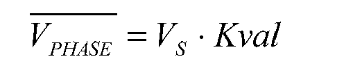
- A way of compensating the BEMF voltage consists in acting on the amplitude of the sinusoidal voltage by varying the value Kval. The compensation factor can be simply multiplied to the original Kval value imposed by the user.
- By developing the above VPHASE vs. IPHASE approximated relationship:

- According to another embodiment, two different Kval values are used, depending on the motor speed:

FIG. 11 compares the stacked line defined by the above equation and the ideal characteristic. - An exemplary digital circuit for generating PWM signals with a duty cycle amplitude determined according to the stacked line characteristic of
FIG. 11 is shown inFIG. 12 . - Different parameter values can be programmed according to motor and system characteristics and depending on the desired type of dynamic operation (torque, acceleration, speed, etc).
- Another drawback of voltage mode driving consists in the undesired dependence of the produced torque from the supply voltage of the power bridges that drive the stepper motor, as illustrated in
FIG. 6 . - Numerous motor stepper drivers use power bridges to energize the phase motor inductances with a PWM switching technique to modulate energy in a desired way. By regulating the duty cycle of each half bridge is possible to control the average phase voltage in a PWM switching period. In case of voltage mode approach, the applied average voltage is directly proportional to the effective duty cycle applied to each power full bridge and the power stage supply voltage. This means that, if the supply voltage was constant, the control of the average phase voltage would be very easy to implement at controller level.
- Unfortunately, in most of real motor applications, the supply voltage is not well regulated and it may undergo to significant voltage fluctuations, due to various factors, for example to fluctuations of load conditions of a voltage regulator that delivers the supply voltage of the motor. The effect of supply voltage fluctuations is shown in
FIG. 6 : the dependence of average phase voltage on both supply voltage and duty cycle produces an undesired amplitude modulation in typical sinusoidal waveforms that causes undesired variations of the produced torque. Therefore, the torque is not constant but depends on the supply voltage. This dependence may have a double negative impact: - torque fluctuations may cause acoustic noise and vibration in resonance with supply voltage fluctuations, and
- any drop of the supply voltage may cause a corresponding drop of the produced torque, that could attain the value of the detent torque of the driven motor thus risking to loose steps and/or stalling the stepper motor.
- Considering that the average phase voltage is proportional to the motor supply voltage (VS), any variation of the supply voltage from its nominal value (VS,nom) affects the system performances. In terms of Kval:

- Motor supply voltage variation can be expressed by a coefficient δVS:

- According to another embodiment of the novel voltage mode driving method, the parameter Kval is varied as depicted in
FIG. 13 . The parameter δVS is compensated multiplying Kval by a compensation coefficient C. The coefficient C is obtained as the reciprocal of δVS, for example as schematically illustrated by the block diagram ofFIG. 14 depicting an exemplary control line. - Resulting Kval value (KvalC) is applied to motor phase:

- When a stepper motor driven in voltage mode is near to stall (step loss), the current in its phases rapidly increases. This is due to the fact that the BEMF voltage is proportional to the motor speed and is null when the motor is at rest. When a stall event is imminent or in progress, the phase current abruptly increases, as shown in
FIG. 15 , and this effect could be used to detect stall conditions. Using a programmable comparator is possible to sense this overelongation and to inform the host processor of a possible or incoming stall event. A system capable of detecting motor stall conditions caused by excessive mechanical load (and/or insufficient current) without using any speed sensor is depicted inFIG. 16 . - Analog current comparators may be used to detect when currents through the windings exceed the normal operative range.
-
FIG. 17 depicts a block diagram of the proposed control system. The meaning of each functional block will appear per se clear from the above description and for this reason it will not be illustrated in detail. - The novel driving technique for stepper motors performs very good both in static conditions, in terms of accuracy of rotor positioning, as well as in dynamic conditions, for example in terms of high smoothness and very low noise during motor rotation, optimized torque performances at high speed.
- Moreover, using the novel control method and system it is possible to detect an imminent or in progress stall condition without using position or speed sensors.
- The novel control technique provides the great positioning accuracy typical of stepper motors with the dynamic performances and smoothness typical of common DC motors. The practical implementation of the new motor control system requires a very simple architecture. Indeed, thanks to a reduction of the number of analog blocks, that are typically required in known stepper drivers, the novel control method may be implemented by a fully digital control system.
Claims (8)
- A method of driving a stepper motor in feed-forward voltage mode, comprising the step of:for a desired speed to be impressed to the stepper motor, setting the amplitude of a sinusoidal phase voltage of the stepper motor equal to the sum of the expected back-electromotive force (BEMF) amplitude estimated in function of the desired speed, and the product between a desired amplitude of a phase current (Iphase) and an estimated absolute value of the motor impedance.
- The method of claim 1, comprising the step of:for a desired speed to be impressed to the stepper motor, setting the amplitude of the sinusoidal phase voltage of the stepper motor according to a transfer function that assumes a minimum value (Kvalmin) for speed values smaller than a minimum speed and that increases with a fixed slope (σst) for speed values larger than said minimum speed, said minimum value (Kvalmin), minimum speed and said slope (σst) being pre-determined in function of nominal values of electrical parameters of the stepper motor and of an estimation of back-electromotive force (BEMF) amplitude induced in windings of the motor.
- The method of claim 1 or 2, comprising the steps of:driving in PWM mode said stepper motor at a fixed frequency, where the duty cycle is proportional to said sinusoidal phase voltage.
- The method of claim 2, wherein for speed values larger than a second speed threshold (Speedint) and higher than said minimum speed, said transfer function increases with a second fixed slope (σfn) steeper than said first slope (σst).
- The method of claim 3, further comprising the steps of setting the duty-cycle of the PWM driving for impressing the desired speed to the stepper motor as the ratio between the duty-cycle determined according to claim 3 and to a measured percentage fluctuation (δvs) of the voltage effectively supplied to the stepper motor in respect to its nominal value.
- A method of generating an alarm flag of an imminent or in progress stall condition of the stepper motor driven in feed-forward voltage mode according to the method of claim 1, comprising:comparing the phase current with a threshold, generating said alarm flag when said threshold is surpassed.
- A system for driving a stepper motor in feed-forward voltage mode, comprising:a power stage adapted to energize windings of said stepper motor,a control circuit input with a command representing a speed value to be impressed to the stepper motor, adapted to generate control signals of said power stage for making said stepper motor rotate at said speed to be impressed, characterized in that said control circuit is adapted to generate said control signals such to set the amplitude of sinusoidal phase voltage of the stepper motor according to the method of claim 1.
- The system of claim 7, further including a circuit adapted to generate an alarm flag of an imminent or in progress stall condition of the stepper motor comprising:at least a current sensor generating a sense signal representative of a phase current of the stepper motor;at least a comparator of said sense signal with a threshold, adapted to generate said alarm flag when said threshold is surpassed.
Applications Claiming Priority (1)
| Application Number | Priority Date | Filing Date | Title |
|---|---|---|---|
| ITVA20090031 | 2009-05-14 |
Publications (2)
| Publication Number | Publication Date |
|---|---|
| EP2251972A1 true EP2251972A1 (en) | 2010-11-17 |
| EP2251972B1 EP2251972B1 (en) | 2014-07-02 |
Family
ID=41478729
Family Applications (1)
| Application Number | Title | Priority Date | Filing Date |
|---|---|---|---|
| EP10159984.3A Active EP2251972B1 (en) | 2009-05-14 | 2010-04-15 | Method and hardware system for driving a stepper motor in feed-forward voltage mode |
Country Status (4)
| Country | Link |
|---|---|
| US (1) | US8390235B2 (en) |
| EP (1) | EP2251972B1 (en) |
| JP (1) | JP5740726B2 (en) |
| CN (1) | CN101888207B (en) |
Cited By (1)
| Publication number | Priority date | Publication date | Assignee | Title |
|---|---|---|---|---|
| WO2018072791A1 (en) * | 2016-10-18 | 2018-04-26 | Trinamic Motion Control Gmbh & Co. Kg | Method and circuit arrangement for controlling a stepper motor |
Families Citing this family (13)
| Publication number | Priority date | Publication date | Assignee | Title |
|---|---|---|---|---|
| GB0713239D0 (en) * | 2007-07-07 | 2007-08-15 | Trw Ltd | Electriv motor control |
| WO2012046693A1 (en) | 2010-10-05 | 2012-04-12 | 三菱電機株式会社 | Microstep drive control device for stepping motor |
| KR102136804B1 (en) * | 2013-01-23 | 2020-07-22 | 엘지전자 주식회사 | Motor control apparatus and method thereof |
| US9257920B2 (en) | 2013-07-19 | 2016-02-09 | Stmicroelectronics S.R.L. | Method and related driver of a permanent magnet synchronous electric motor |
| US9768717B2 (en) * | 2014-12-15 | 2017-09-19 | Stmicroelectronics S.R.L. | Method of driving brushless motors, corresponding device, motor and computer program product |
| US10340827B2 (en) * | 2017-11-06 | 2019-07-02 | Steering Solutions Ip Holding Corporation | Fault tolerant current measurement in motor control systems |
| CN110716577B (en) * | 2019-11-13 | 2020-12-15 | 北京航空航天大学 | A sensorless adaptive commutation error compensation method for a magnetic levitation control torque gyro brushless DC motor |
| CN111049437B (en) * | 2019-12-24 | 2021-09-21 | 浙江大华技术股份有限公司 | Method, device, equipment and medium for compensating back electromotive force voltage of stepping motor |
| CN111917346A (en) * | 2020-05-26 | 2020-11-10 | 温州长江汽车电子有限公司 | Step number calculation method and system for stepping motor |
| CN111614292B (en) * | 2020-06-17 | 2021-11-12 | 杭州海康威视数字技术股份有限公司 | Drive control device and drive control method for stepping motor |
| CN114337408B (en) * | 2021-12-27 | 2023-10-27 | 嘉兴禾润电子科技有限公司 | A pulse width modulation driving method with speed compensation for stepper motors |
| CN114665776B (en) * | 2022-05-23 | 2023-01-03 | 深圳市杰美康机电有限公司 | Control method and system for dynamic decoupling of closed-loop stepping motor and storage medium |
| US12316266B2 (en) * | 2023-05-31 | 2025-05-27 | Texas Instruments Incorporated | Methods and apparatus to detect a stall of a stepper motor |
Citations (3)
| Publication number | Priority date | Publication date | Assignee | Title |
|---|---|---|---|---|
| US5216345A (en) * | 1992-05-04 | 1993-06-01 | Hughes Aircraft Company | Mixed mode stepper motor controller and method |
| EP0736961A1 (en) * | 1995-04-07 | 1996-10-09 | Magneti Marelli France | Angular control device for a stepping motor |
| US6150789A (en) * | 1999-02-13 | 2000-11-21 | Tri-Tech, Inc. | Stepper motor control |
Family Cites Families (9)
| Publication number | Priority date | Publication date | Assignee | Title |
|---|---|---|---|---|
| CH653206GA3 (en) * | 1983-09-16 | 1985-12-31 | ||
| JPS6088285A (en) * | 1983-10-19 | 1985-05-18 | Matsushita Refrig Co | Solenoid valve for refrigerant line |
| CN2037900U (en) * | 1988-10-20 | 1989-05-17 | 国营北京红旗机械厂 | Synchronous-compensation pulse-power driving system |
| JP2703086B2 (en) * | 1990-01-26 | 1998-01-26 | 東京電力株式会社 | Internal observation device for combustible liquefied gas storage tank |
| JPH03226300A (en) * | 1990-01-31 | 1991-10-07 | Oriental Motor Co Ltd | Driving method and circuit for step motor |
| JP3202517B2 (en) * | 1995-01-17 | 2001-08-27 | アルプス電気株式会社 | Rotation control method of tracking antenna mounted on moving object and rotation control device thereof |
| JP2000023496A (en) * | 1998-07-03 | 2000-01-21 | Nippon Soken Inc | Step motor control device |
| JP2005184926A (en) * | 2003-12-17 | 2005-07-07 | Hitachi Omron Terminal Solutions Corp | Stepping motor drive control |
| US20090058330A1 (en) * | 2007-08-30 | 2009-03-05 | Seagate Technology Llc | Driving a multi-phased motor |
-
2010
- 2010-04-15 EP EP10159984.3A patent/EP2251972B1/en active Active
- 2010-05-06 JP JP2010106511A patent/JP5740726B2/en active Active
- 2010-05-13 US US12/779,591 patent/US8390235B2/en active Active
- 2010-05-14 CN CN201010184188.1A patent/CN101888207B/en active Active
Patent Citations (3)
| Publication number | Priority date | Publication date | Assignee | Title |
|---|---|---|---|---|
| US5216345A (en) * | 1992-05-04 | 1993-06-01 | Hughes Aircraft Company | Mixed mode stepper motor controller and method |
| EP0736961A1 (en) * | 1995-04-07 | 1996-10-09 | Magneti Marelli France | Angular control device for a stepping motor |
| US6150789A (en) * | 1999-02-13 | 2000-11-21 | Tri-Tech, Inc. | Stepper motor control |
Cited By (1)
| Publication number | Priority date | Publication date | Assignee | Title |
|---|---|---|---|---|
| WO2018072791A1 (en) * | 2016-10-18 | 2018-04-26 | Trinamic Motion Control Gmbh & Co. Kg | Method and circuit arrangement for controlling a stepper motor |
Also Published As
| Publication number | Publication date |
|---|---|
| JP5740726B2 (en) | 2015-06-24 |
| US20100289445A1 (en) | 2010-11-18 |
| US8390235B2 (en) | 2013-03-05 |
| JP2010268675A (en) | 2010-11-25 |
| EP2251972B1 (en) | 2014-07-02 |
| CN101888207B (en) | 2015-04-22 |
| CN101888207A (en) | 2010-11-17 |
Similar Documents
| Publication | Publication Date | Title |
|---|---|---|
| EP2251972B1 (en) | Method and hardware system for driving a stepper motor in feed-forward voltage mode | |
| US9998059B2 (en) | Motor driving apparatus | |
| US6498449B1 (en) | Low ripple torque control of a permanent magnet motor without using current sensors | |
| JP5610651B2 (en) | Brushless motor control device and brushless motor control method | |
| JP2007028886A (en) | Control method of sensorless BLDC motor | |
| CN105453410A (en) | Control device and ac electric motor system using same | |
| JP7361924B2 (en) | Motor control device, motor control method | |
| KR101448677B1 (en) | Apparatus and method for estimating rotor position of brushless dc motor | |
| US12255558B2 (en) | Motor controller, motor system and method for controlling motor | |
| JP2017055637A (en) | Motor control device for controlling motor based on counter electromotive voltage generated in motor winding | |
| CN114616753B (en) | Power conversion device, power conversion method, and power conversion system | |
| JP2017131000A (en) | Sensorless drive method for three-phase brushless motor | |
| KR20150031356A (en) | Apparatus and method for compensating reference voltage in bldc motor control system | |
| US20250233536A1 (en) | Method for Detecting Field Magnet Position of an Electric Motor | |
| KR101225165B1 (en) | Method to control starting of sensorless Permanent Magnet Synchronous Motor | |
| US11165373B2 (en) | Motor driving apparatus | |
| US12176841B2 (en) | Method and circuit arrangement for controlling a stepper motor | |
| CN103187906B (en) | Method, system and apparatus for generating voltage commands for controlling operation of permanent magnet motors | |
| JP5651322B2 (en) | Power converter | |
| US9257920B2 (en) | Method and related driver of a permanent magnet synchronous electric motor | |
| JP6574711B2 (en) | Method for measuring the inductance of a permanent magnet synchronous motor | |
| US20250253783A1 (en) | Method for Detecting Field Magnet Position of an Electric Motor | |
| US20260074639A1 (en) | Motor control device and motor control method | |
| KR20090008944A (en) | Drive device and method for DC motor | |
| KR102509725B1 (en) | Motor drive apparatus |
Legal Events
| Date | Code | Title | Description |
|---|---|---|---|
| PUAI | Public reference made under article 153(3) epc to a published international application that has entered the european phase |
Free format text: ORIGINAL CODE: 0009012 |
|
| AK | Designated contracting states |
Kind code of ref document: A1 Designated state(s): AT BE BG CH CY CZ DE DK EE ES FI FR GB GR HR HU IE IS IT LI LT LU LV MC MK MT NL NO PL PT RO SE SI SK SM TR |
|
| AX | Request for extension of the european patent |
Extension state: AL BA ME RS |
|
| 17P | Request for examination filed |
Effective date: 20110509 |
|
| RAP1 | Party data changed (applicant data changed or rights of an application transferred) |
Owner name: DORA S.P.A. Owner name: STMICROELECTRONICS SRL |
|
| GRAP | Despatch of communication of intention to grant a patent |
Free format text: ORIGINAL CODE: EPIDOSNIGR1 |
|
| INTG | Intention to grant announced |
Effective date: 20140122 |
|
| GRAS | Grant fee paid |
Free format text: ORIGINAL CODE: EPIDOSNIGR3 |
|
| GRAA | (expected) grant |
Free format text: ORIGINAL CODE: 0009210 |
|
| AK | Designated contracting states |
Kind code of ref document: B1 Designated state(s): AT BE BG CH CY CZ DE DK EE ES FI FR GB GR HR HU IE IS IT LI LT LU LV MC MK MT NL NO PL PT RO SE SI SK SM TR |
|
| REG | Reference to a national code |
Ref country code: GB Ref legal event code: FG4D |
|
| REG | Reference to a national code |
Ref country code: CH Ref legal event code: EP |
|
| REG | Reference to a national code |
Ref country code: IE Ref legal event code: FG4D |
|
| REG | Reference to a national code |
Ref country code: DE Ref legal event code: R096 Ref document number: 602010017155 Country of ref document: DE Effective date: 20140814 |
|
| REG | Reference to a national code |
Ref country code: NL Ref legal event code: VDEP Effective date: 20140702 |
|
| REG | Reference to a national code |
Ref country code: AT Ref legal event code: REF Ref document number: 700157 Country of ref document: AT Kind code of ref document: T Effective date: 20141215 |
|
| REG | Reference to a national code |
Ref country code: LT Ref legal event code: MG4D |
|
| PG25 | Lapsed in a contracting state [announced via postgrant information from national office to epo] |
Ref country code: NO Free format text: LAPSE BECAUSE OF FAILURE TO SUBMIT A TRANSLATION OF THE DESCRIPTION OR TO PAY THE FEE WITHIN THE PRESCRIBED TIME-LIMIT Effective date: 20141002 Ref country code: CZ Free format text: LAPSE BECAUSE OF FAILURE TO SUBMIT A TRANSLATION OF THE DESCRIPTION OR TO PAY THE FEE WITHIN THE PRESCRIBED TIME-LIMIT Effective date: 20140702 Ref country code: ES Free format text: LAPSE BECAUSE OF FAILURE TO SUBMIT A TRANSLATION OF THE DESCRIPTION OR TO PAY THE FEE WITHIN THE PRESCRIBED TIME-LIMIT Effective date: 20140702 Ref country code: BG Free format text: LAPSE BECAUSE OF FAILURE TO SUBMIT A TRANSLATION OF THE DESCRIPTION OR TO PAY THE FEE WITHIN THE PRESCRIBED TIME-LIMIT Effective date: 20141002 Ref country code: GR Free format text: LAPSE BECAUSE OF FAILURE TO SUBMIT A TRANSLATION OF THE DESCRIPTION OR TO PAY THE FEE WITHIN THE PRESCRIBED TIME-LIMIT Effective date: 20141003 Ref country code: LT Free format text: LAPSE BECAUSE OF FAILURE TO SUBMIT A TRANSLATION OF THE DESCRIPTION OR TO PAY THE FEE WITHIN THE PRESCRIBED TIME-LIMIT Effective date: 20140702 Ref country code: FI Free format text: LAPSE BECAUSE OF FAILURE TO SUBMIT A TRANSLATION OF THE DESCRIPTION OR TO PAY THE FEE WITHIN THE PRESCRIBED TIME-LIMIT Effective date: 20140702 Ref country code: PT Free format text: LAPSE BECAUSE OF FAILURE TO SUBMIT A TRANSLATION OF THE DESCRIPTION OR TO PAY THE FEE WITHIN THE PRESCRIBED TIME-LIMIT Effective date: 20141103 Ref country code: SE Free format text: LAPSE BECAUSE OF FAILURE TO SUBMIT A TRANSLATION OF THE DESCRIPTION OR TO PAY THE FEE WITHIN THE PRESCRIBED TIME-LIMIT Effective date: 20140702 |
|
| PG25 | Lapsed in a contracting state [announced via postgrant information from national office to epo] |
Ref country code: LV Free format text: LAPSE BECAUSE OF FAILURE TO SUBMIT A TRANSLATION OF THE DESCRIPTION OR TO PAY THE FEE WITHIN THE PRESCRIBED TIME-LIMIT Effective date: 20140702 Ref country code: PL Free format text: LAPSE BECAUSE OF FAILURE TO SUBMIT A TRANSLATION OF THE DESCRIPTION OR TO PAY THE FEE WITHIN THE PRESCRIBED TIME-LIMIT Effective date: 20140702 Ref country code: IS Free format text: LAPSE BECAUSE OF FAILURE TO SUBMIT A TRANSLATION OF THE DESCRIPTION OR TO PAY THE FEE WITHIN THE PRESCRIBED TIME-LIMIT Effective date: 20141102 Ref country code: CY Free format text: LAPSE BECAUSE OF FAILURE TO SUBMIT A TRANSLATION OF THE DESCRIPTION OR TO PAY THE FEE WITHIN THE PRESCRIBED TIME-LIMIT Effective date: 20140702 Ref country code: HR Free format text: LAPSE BECAUSE OF FAILURE TO SUBMIT A TRANSLATION OF THE DESCRIPTION OR TO PAY THE FEE WITHIN THE PRESCRIBED TIME-LIMIT Effective date: 20140702 Ref country code: NL Free format text: LAPSE BECAUSE OF FAILURE TO SUBMIT A TRANSLATION OF THE DESCRIPTION OR TO PAY THE FEE WITHIN THE PRESCRIBED TIME-LIMIT Effective date: 20140702 |
|
| REG | Reference to a national code |
Ref country code: AT Ref legal event code: MK05 Ref document number: 700157 Country of ref document: AT Kind code of ref document: T Effective date: 20140702 |
|
| REG | Reference to a national code |
Ref country code: DE Ref legal event code: R097 Ref document number: 602010017155 Country of ref document: DE |
|
| PG25 | Lapsed in a contracting state [announced via postgrant information from national office to epo] |
Ref country code: EE Free format text: LAPSE BECAUSE OF FAILURE TO SUBMIT A TRANSLATION OF THE DESCRIPTION OR TO PAY THE FEE WITHIN THE PRESCRIBED TIME-LIMIT Effective date: 20140702 Ref country code: IT Free format text: LAPSE BECAUSE OF FAILURE TO SUBMIT A TRANSLATION OF THE DESCRIPTION OR TO PAY THE FEE WITHIN THE PRESCRIBED TIME-LIMIT Effective date: 20140702 Ref country code: DK Free format text: LAPSE BECAUSE OF FAILURE TO SUBMIT A TRANSLATION OF THE DESCRIPTION OR TO PAY THE FEE WITHIN THE PRESCRIBED TIME-LIMIT Effective date: 20140702 Ref country code: SK Free format text: LAPSE BECAUSE OF FAILURE TO SUBMIT A TRANSLATION OF THE DESCRIPTION OR TO PAY THE FEE WITHIN THE PRESCRIBED TIME-LIMIT Effective date: 20140702 Ref country code: RO Free format text: LAPSE BECAUSE OF FAILURE TO SUBMIT A TRANSLATION OF THE DESCRIPTION OR TO PAY THE FEE WITHIN THE PRESCRIBED TIME-LIMIT Effective date: 20140702 |
|
| PLBE | No opposition filed within time limit |
Free format text: ORIGINAL CODE: 0009261 |
|
| STAA | Information on the status of an ep patent application or granted ep patent |
Free format text: STATUS: NO OPPOSITION FILED WITHIN TIME LIMIT |
|
| REG | Reference to a national code |
Ref country code: DE Ref legal event code: R082 Ref document number: 602010017155 Country of ref document: DE |
|
| PG25 | Lapsed in a contracting state [announced via postgrant information from national office to epo] |
Ref country code: AT Free format text: LAPSE BECAUSE OF FAILURE TO SUBMIT A TRANSLATION OF THE DESCRIPTION OR TO PAY THE FEE WITHIN THE PRESCRIBED TIME-LIMIT Effective date: 20140702 |
|
| 26N | No opposition filed |
Effective date: 20150407 |
|
| PG25 | Lapsed in a contracting state [announced via postgrant information from national office to epo] |
Ref country code: MC Free format text: LAPSE BECAUSE OF FAILURE TO SUBMIT A TRANSLATION OF THE DESCRIPTION OR TO PAY THE FEE WITHIN THE PRESCRIBED TIME-LIMIT Effective date: 20140702 Ref country code: LU Free format text: LAPSE BECAUSE OF FAILURE TO SUBMIT A TRANSLATION OF THE DESCRIPTION OR TO PAY THE FEE WITHIN THE PRESCRIBED TIME-LIMIT Effective date: 20150415 Ref country code: SI Free format text: LAPSE BECAUSE OF FAILURE TO SUBMIT A TRANSLATION OF THE DESCRIPTION OR TO PAY THE FEE WITHIN THE PRESCRIBED TIME-LIMIT Effective date: 20140702 |
|
| REG | Reference to a national code |
Ref country code: CH Ref legal event code: PL |
|
| GBPC | Gb: european patent ceased through non-payment of renewal fee |
Effective date: 20150415 |
|
| REG | Reference to a national code |
Ref country code: IE Ref legal event code: MM4A |
|
| PG25 | Lapsed in a contracting state [announced via postgrant information from national office to epo] |
Ref country code: CH Free format text: LAPSE BECAUSE OF NON-PAYMENT OF DUE FEES Effective date: 20150430 Ref country code: GB Free format text: LAPSE BECAUSE OF NON-PAYMENT OF DUE FEES Effective date: 20150415 Ref country code: LI Free format text: LAPSE BECAUSE OF NON-PAYMENT OF DUE FEES Effective date: 20150430 |
|
| REG | Reference to a national code |
Ref country code: FR Ref legal event code: ST Effective date: 20151231 |
|
| PG25 | Lapsed in a contracting state [announced via postgrant information from national office to epo] |
Ref country code: FR Free format text: LAPSE BECAUSE OF NON-PAYMENT OF DUE FEES Effective date: 20150430 |
|
| REG | Reference to a national code |
Ref country code: DE Ref legal event code: R081 Ref document number: 602010017155 Country of ref document: DE Owner name: STMICROELECTRONICS S.R.L., IT Free format text: FORMER OWNER: DORA S.P.A., AOSTA, IT |
|
| PG25 | Lapsed in a contracting state [announced via postgrant information from national office to epo] |
Ref country code: IE Free format text: LAPSE BECAUSE OF NON-PAYMENT OF DUE FEES Effective date: 20150415 |
|
| PG25 | Lapsed in a contracting state [announced via postgrant information from national office to epo] |
Ref country code: BE Free format text: LAPSE BECAUSE OF FAILURE TO SUBMIT A TRANSLATION OF THE DESCRIPTION OR TO PAY THE FEE WITHIN THE PRESCRIBED TIME-LIMIT Effective date: 20140702 |
|
| PG25 | Lapsed in a contracting state [announced via postgrant information from national office to epo] |
Ref country code: MT Free format text: LAPSE BECAUSE OF FAILURE TO SUBMIT A TRANSLATION OF THE DESCRIPTION OR TO PAY THE FEE WITHIN THE PRESCRIBED TIME-LIMIT Effective date: 20140702 |
|
| PG25 | Lapsed in a contracting state [announced via postgrant information from national office to epo] |
Ref country code: HU Free format text: LAPSE BECAUSE OF FAILURE TO SUBMIT A TRANSLATION OF THE DESCRIPTION OR TO PAY THE FEE WITHIN THE PRESCRIBED TIME-LIMIT; INVALID AB INITIO Effective date: 20100415 Ref country code: SM Free format text: LAPSE BECAUSE OF FAILURE TO SUBMIT A TRANSLATION OF THE DESCRIPTION OR TO PAY THE FEE WITHIN THE PRESCRIBED TIME-LIMIT Effective date: 20140702 |
|
| PG25 | Lapsed in a contracting state [announced via postgrant information from national office to epo] |
Ref country code: TR Free format text: LAPSE BECAUSE OF FAILURE TO SUBMIT A TRANSLATION OF THE DESCRIPTION OR TO PAY THE FEE WITHIN THE PRESCRIBED TIME-LIMIT Effective date: 20140702 |
|
| PG25 | Lapsed in a contracting state [announced via postgrant information from national office to epo] |
Ref country code: MK Free format text: LAPSE BECAUSE OF FAILURE TO SUBMIT A TRANSLATION OF THE DESCRIPTION OR TO PAY THE FEE WITHIN THE PRESCRIBED TIME-LIMIT Effective date: 20140702 |
|
| PGFP | Annual fee paid to national office [announced via postgrant information from national office to epo] |
Ref country code: DE Payment date: 20250319 Year of fee payment: 16 |