EP2251961B1 - Carrier for electronic components, and electric motor - Google Patents
Carrier for electronic components, and electric motor Download PDFInfo
- Publication number
- EP2251961B1 EP2251961B1 EP09305438A EP09305438A EP2251961B1 EP 2251961 B1 EP2251961 B1 EP 2251961B1 EP 09305438 A EP09305438 A EP 09305438A EP 09305438 A EP09305438 A EP 09305438A EP 2251961 B1 EP2251961 B1 EP 2251961B1
- Authority
- EP
- European Patent Office
- Prior art keywords
- carrier
- housing
- electric motor
- layer
- electronic components
- Prior art date
- Legal status (The legal status is an assumption and is not a legal conclusion. Google has not performed a legal analysis and makes no representation as to the accuracy of the status listed.)
- Not-in-force
Links
- 239000002918 waste heat Substances 0.000 claims description 4
- 238000001816 cooling Methods 0.000 description 3
- 239000000969 carrier Substances 0.000 description 2
- 238000009749 continuous casting Methods 0.000 description 1
- 239000002184 metal Substances 0.000 description 1
- 229910000679 solder Inorganic materials 0.000 description 1
Images

Classifications
-
- H—ELECTRICITY
- H02—GENERATION; CONVERSION OR DISTRIBUTION OF ELECTRIC POWER
- H02K—DYNAMO-ELECTRIC MACHINES
- H02K11/00—Structural association of dynamo-electric machines with electric components or with devices for shielding, monitoring or protection
- H02K11/30—Structural association with control circuits or drive circuits
- H02K11/33—Drive circuits, e.g. power electronics
-
- H—ELECTRICITY
- H02—GENERATION; CONVERSION OR DISTRIBUTION OF ELECTRIC POWER
- H02K—DYNAMO-ELECTRIC MACHINES
- H02K9/00—Arrangements for cooling or ventilating
- H02K9/22—Arrangements for cooling or ventilating by solid heat conducting material embedded in, or arranged in contact with, the stator or rotor, e.g. heat bridges
- H02K9/227—Heat sinks
-
- H—ELECTRICITY
- H02—GENERATION; CONVERSION OR DISTRIBUTION OF ELECTRIC POWER
- H02K—DYNAMO-ELECTRIC MACHINES
- H02K2211/00—Specific aspects not provided for in the other groups of this subclass relating to measuring or protective devices or electric components
- H02K2211/03—Machines characterised by circuit boards, e.g. pcb
Definitions
- the invention relates to a carrier for electronic components, especially including power electronics components, especially for use inside a metallic housing of an electric motor, with means for transfer of waste heat, according to the preamble of claim 1, and to an electric motor, especially a brushless DC motor, with a housing and with electronic components included inside the housing, according to the preamble of claim 4.
- Power electronics components for controlling brushless DC motors often are integral parts of such motors. It is known to use internally applied carrying such power electronics components together with related position sensors and control elements. Then the problem is to be solved of how to thermally contact the power electronics components and the motor housing, then acting as a heat sink.
- DE 10 2007 014 645 A1 discloses a housing 6 in which an electric motor 3 is located. Furthermore, a cooling element 14 with a radial edge 15 is comprised in the housing 6. The cooling element 6 carries electronic components. This solution requires additional measures to ensure a good thermal contact between the cooling element 14 and the housing 6.
- the invention makes use of the availability of flexible printed circuit boards that can do both, transfer the heat, and give the necessary mechanical pressure to ensure a good thermal contact.
- Figure 1 shows a very schematic cross-sectional view of an electric motor M according to the invention. Only a housing H and a carrier C according to the invention are shown.
- the housing H represents not only the housing as such but also all other parts of the motor that are to be assembled before connecting rotor or stator coils to control elements.
- these parts are mainly a stator with stator coils, an axle with a rotor with permanent magnets, and a positioning encoder (e.g. a magnet) affixed to the axle.
- stator may carry permanent magnets, and the rotor will carry the coils; in this case a collector will ensure the electric contact between fixed and rotating parts; but such motors seldom include power electronics components.
- the housing at the bottom (in this view) will be completed by an end shield carrying bearings for the axle, mostly ball bearings. And in addition often there are special mountings to attach the motor where needed.
- the carrier C is shown.
- it is composed out of three layers of a multilayer printed circuit board.
- the upper and the lower layer are non-flexible layers, whereas the middle layer is a flexible one.
- the non-flexible ones carry the components and their connections, and only to a minor extend serve transferring the heat, while the flexible one serves for transferring the heat from the components to the housing H of the motor M.
- stator and rotor are to be inserted into the housing H
- the blank carrier which as such already is considered to be a carrier according to the invention, is to be equipped with components.
- the stator carries stator coils that end in connection pins extending in the axial direction of the motor M.
- the carrier shows solder points and related bore-holes fitting on those connection pins and to be soldered therewith.
- Figure 2 shows such carrier C, from above or from below. It is assumed here, that the cross-section of the housing H of the motor M is a circular one. In this case also the carrier C in principle is circular.
- the non-flexible layer L1 displayed with fine dots, and the flexible layer L2, the visible part displayed in black.
- the non-flexible layer L1 does not show any structure here because this is not influenced by the invention.
- the flexible layer L2 comprises a uniform part with a shape identical to that of the non-flexible layer L1, and a multiple of protruding ranges PR radially extending outwards.
- Number and form of the protruding ranges PR depend on the form of the layer, which as such depends on the cross-section of the motor's housing H.
- a circular housing asks for circular layers and for a high number of equally distributed like protruding ranges PR, while a quadratic housing would ask for quadratic layers and only four like protruding ranges PR.
- the whole layer L2 is flexible, the protruding ranges PR are flexible as well. This flexibility ensures a smooth thermal contact between this layer and the housing H of the motor M. This thermal contact may be improved by the use of an additional flexible element like a circlip provided after inserting the carrier C into the housing H.
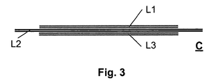
- Figure 3 finally shows the carrier C in a cross-sectional view before being equipped with components and before having been inserted into the motor's housing H.
Landscapes
- Engineering & Computer Science (AREA)
- Power Engineering (AREA)
- Microelectronics & Electronic Packaging (AREA)
- Motor Or Generator Frames (AREA)
Description
- The invention relates to a carrier for electronic components, especially including power electronics components, especially for use inside a metallic housing of an electric motor, with means for transfer of waste heat, according to the preamble of claim 1, and to an electric motor, especially a brushless DC motor, with a housing and with electronic components included inside the housing, according to the preamble of claim 4.
- Power electronics components for controlling brushless DC motors often are integral parts of such motors. It is known to use internally applied carrying such power electronics components together with related position sensors and control elements. Then the problem is to be solved of how to thermally contact the power electronics components and the motor housing, then acting as a heat sink.
- A first solution to this problem is given in
US 7,161,268 B2, issued to Bernhard M. Kaiser , internal docket 114413. There the printed circuit board is arranged perpendicular to the axle of the motor with the power electronics components standing upright and spread along the circumference of such board. A separate intermediate heat sink is used to transfer the heat from the power electronics components to the housing. The power electronics components are screwed onto such intermediate heat sink, which on the other side is pressed to the housing by means of a circlip. An alternative solution is given inEP 1 876 689 B1 . Both solutions need additionally to be mounted components and both need an additional step to achieve the necessary pressure between the heat dissipating elements. -
DE 10 2007 014 645 A1 discloses a housing 6 in which an electric motor 3 is located. Furthermore, a cooling element 14 with a radial edge 15 is comprised in the housing 6. The cooling element 6 carries electronic components. This solution requires additional measures to ensure a good thermal contact between the cooling element 14 and the housing 6. - According to the invention this problem is solved by a carrier according to the teaching of claim 1, and by an electric motor according to the teaching of claim 4.
- The invention makes use of the availability of flexible printed circuit boards that can do both, transfer the heat, and give the necessary mechanical pressure to ensure a good thermal contact.
- It is obvious that carriers according to the teaching of claim 1 are not only valuable for the controlling of brushless DC motors, as mentioned as starting point of this invention, but such carriers are valuable in lots of situations, where waste heat producing parts and related heat sinks are to be mounted separately and only later come into thermal contact. Further embodiments of the invention are given in the subclaims and in the following description.
- In the following the invention will be described with the aid of the accompanying drawings, in which:
- Figure 1
- shows a very schematic cross-sectional view of an electric motor according to the invention with a carrier according to the invention.
- Figure 2
- shows a top view of a carrier according to the invention, without any components mounted thereon.
- Figure 3
- shows a cross-sectional view of the carrier shown in
figure 2 . -
Figure 1 shows a very schematic cross-sectional view of an electric motor M according to the invention. Only a housing H and a carrier C according to the invention are shown. - The housing H represents not only the housing as such but also all other parts of the motor that are to be assembled before connecting rotor or stator coils to control elements.
- In the case of a brushless DC motor these parts are mainly a stator with stator coils, an axle with a rotor with permanent magnets, and a positioning encoder (e.g. a magnet) affixed to the axle.
- Otherwise the stator may carry permanent magnets, and the rotor will carry the coils; in this case a collector will ensure the electric contact between fixed and rotating parts; but such motors seldom include power electronics components.
- In any case the housing at the bottom (in this view) will be completed by an end shield carrying bearings for the axle, mostly ball bearings. And in addition often there are special mountings to attach the motor where needed.
- The main part of the housing, not the end shield, often is made in continuous casting out of metal. So it gives the opportunity to also act as heat sink.
- In a likewise very schematic way the carrier C is shown. In this example it is composed out of three layers of a multilayer printed circuit board. The upper and the lower layer are non-flexible layers, whereas the middle layer is a flexible one. The non-flexible ones carry the components and their connections, and only to a minor extend serve transferring the heat, while the flexible one serves for transferring the heat from the components to the housing H of the motor M.
- This kind of sandwich structure is of particular advantage even in cases where only one layer would suffice to carry the components and their connections. In such case either of the outer non-flexible layers may show a closed conducting area both, for additional heat transfer capabilities, and for improvement of electromagnetic compliance. But of course also further layers may prove necessary according to normal circuit design and layout.
- For assembling such motor M, on the one hand stator and rotor are to be inserted into the housing H, on the other hand the blank carrier, which as such already is considered to be a carrier according to the invention, is to be equipped with components. The stator carries stator coils that end in connection pins extending in the axial direction of the motor M. The carrier shows solder points and related bore-holes fitting on those connection pins and to be soldered therewith.
-
Figure 2 shows such carrier C, from above or from below. It is assumed here, that the cross-section of the housing H of the motor M is a circular one. In this case also the carrier C in principle is circular. We see one non-flexible layer L1 displayed with fine dots, and the flexible layer L2, the visible part displayed in black. The non-flexible layer L1 does not show any structure here because this is not influenced by the invention. The flexible layer L2 comprises a uniform part with a shape identical to that of the non-flexible layer L1, and a multiple of protruding ranges PR radially extending outwards. - Number and form of the protruding ranges PR depend on the form of the layer, which as such depends on the cross-section of the motor's housing H. A circular housing asks for circular layers and for a high number of equally distributed like protruding ranges PR, while a quadratic housing would ask for quadratic layers and only four like protruding ranges PR.
- As in this example the whole layer L2 is flexible, the protruding ranges PR are flexible as well. This flexibility ensures a smooth thermal contact between this layer and the housing H of the motor M. This thermal contact may be improved by the use of an additional flexible element like a circlip provided after inserting the carrier C into the housing H.
-
Figure 3 finally shows the carrier C in a cross-sectional view before being equipped with components and before having been inserted into the motor's housing H. Here we see the already mentioned non-flexible layer L1 and the flexible layer L2, but also the other non-flexible layer L3.
Claims (4)
- Carrier (C) for electronic components, especially including power electronic components, for use inside a metallic housing (H) of an electric motor (M), wherein said carrier (C) comprises means for transfer of waste heat, and wherein said carrier (C) includes at least two layers (L1, L2, L3), from which at least the first layer (L1) serves for the mounting of the components and their electric contacting, and the second layer (L2) serves as the means for transfer of waste heat,
characterized in that
the second layer includes a multiple of protruding ranges (PR) radially extending outwards, which are in such a manner flexible, that the carrier (C) may thereby be flexibly held in the housing (H) of the electric motor (M) which ensures a smooth thermal contact between this layer (L2) and the housing (H) of the motor (M). - Carrier (C) according to claim 1, characterized in, that it is assembled with electronic components.
- Carrier (C) according to claim 1, characterized in, that the second layer (L2) protrudes over the first layer (L1) and that the protruding ranges (PR) include several areas for flexibly holding.
- Electric motor (M), especially a brushless DC motor, wherein said electric motor (M) comprises a housing (H) and electronic components included inside the housing (H), characterized in that the electric motor (M) comprises a carrier (C) according to claim 1, wherein at least part of the electronic components is mounted on the carrier (C), and wherein the carrier (c) is flexibly held within the housing (H).
Priority Applications (1)
| Application Number | Priority Date | Filing Date | Title |
|---|---|---|---|
| EP09305438A EP2251961B1 (en) | 2009-05-15 | 2009-05-15 | Carrier for electronic components, and electric motor |
Applications Claiming Priority (1)
| Application Number | Priority Date | Filing Date | Title |
|---|---|---|---|
| EP09305438A EP2251961B1 (en) | 2009-05-15 | 2009-05-15 | Carrier for electronic components, and electric motor |
Publications (2)
| Publication Number | Publication Date |
|---|---|
| EP2251961A1 EP2251961A1 (en) | 2010-11-17 |
| EP2251961B1 true EP2251961B1 (en) | 2012-11-14 |
Family
ID=41682311
Family Applications (1)
| Application Number | Title | Priority Date | Filing Date |
|---|---|---|---|
| EP09305438A Not-in-force EP2251961B1 (en) | 2009-05-15 | 2009-05-15 | Carrier for electronic components, and electric motor |
Country Status (1)
| Country | Link |
|---|---|
| EP (1) | EP2251961B1 (en) |
Families Citing this family (1)
| Publication number | Priority date | Publication date | Assignee | Title |
|---|---|---|---|---|
| JP7084810B2 (en) * | 2018-07-13 | 2022-06-15 | 本田技研工業株式会社 | Drive unit |
Family Cites Families (4)
| Publication number | Priority date | Publication date | Assignee | Title |
|---|---|---|---|---|
| DE202004009866U1 (en) | 2004-06-23 | 2004-09-02 | Alcatel | Heat sink arrangement, electric motor and housing part |
| US7273357B2 (en) * | 2005-08-10 | 2007-09-25 | Mitsubishi Heavy Industries, Ltd. | Control device for electric compressor |
| DE602006006169D1 (en) | 2006-07-06 | 2009-05-20 | Alcatel Lucent | Heat sink for an electric motor |
| DE102007014645A1 (en) * | 2007-03-27 | 2008-10-30 | Continental Automotive Gmbh | Electrical component for electrical power steering of motor vehicle, has heat sink with radial edge that has diameter corresponding to inner side diameter of tubular housing, where heat sink is inserted into housing of electric motor |
-
2009
- 2009-05-15 EP EP09305438A patent/EP2251961B1/en not_active Not-in-force
Also Published As
| Publication number | Publication date |
|---|---|
| EP2251961A1 (en) | 2010-11-17 |
Similar Documents
| Publication | Publication Date | Title |
|---|---|---|
| US7245056B2 (en) | Axial fan motor and cooling unit | |
| US7635046B2 (en) | Electric power steering apparatus | |
| JP5528329B2 (en) | Control device-integrated electric power steering apparatus motor and electric power steering apparatus | |
| JP5001662B2 (en) | Electric power steering device | |
| EP2571147A1 (en) | Electric driving device and electric power steering device equipped with same | |
| US20150216083A1 (en) | Power Conversion Apparatus | |
| EP2390676A1 (en) | Electromagnetic coil structure having a flat conductive track, magnetic core and magneto electronic angle sensor | |
| US8113775B2 (en) | Axial flow fan | |
| JP6087123B2 (en) | Brushless motor | |
| US9257876B2 (en) | Motor integrated to electronic device | |
| US20170324284A1 (en) | Actuator with coated stator and rotor modules | |
| CN101847904B (en) | Flat vibration motor | |
| JP6696332B2 (en) | Printed board | |
| EP3684154B1 (en) | Thermally conductive insert element for electronic unit | |
| JP5756179B2 (en) | DC electric motor having flexible rotor assembly and method of manufacturing the same | |
| JP5200521B2 (en) | Motor and cooling fan | |
| JP4697597B2 (en) | Busbar and motor | |
| US6351044B1 (en) | Cooling apparatus for an electronic device integrally formed with a circuit board | |
| EP1995853A1 (en) | Electric Motor | |
| US20140042840A1 (en) | Permanent magnet (pm) electric machine including permanent magnets provided with a thermal interface material (tim) between adjacent permanent magnets | |
| CN102315745B (en) | Motor Yuzzi | |
| EP2251961A1 (en) | Carrier for electronic components, and electric motor | |
| JP5139262B2 (en) | Wet operation pump | |
| EP3607206B1 (en) | Electric pump | |
| US11121606B2 (en) | Motor, circuit board, and engine cooling module including the motor |
Legal Events
| Date | Code | Title | Description |
|---|---|---|---|
| PUAI | Public reference made under article 153(3) epc to a published international application that has entered the european phase |
Free format text: ORIGINAL CODE: 0009012 |
|
| AK | Designated contracting states |
Kind code of ref document: A1 Designated state(s): AT BE BG CH CY CZ DE DK EE ES FI FR GB GR HR HU IE IS IT LI LT LU LV MC MK MT NL NO PL PT RO SE SI SK TR |
|
| 17P | Request for examination filed |
Effective date: 20110324 |
|
| 17Q | First examination report despatched |
Effective date: 20110624 |
|
| GRAP | Despatch of communication of intention to grant a patent |
Free format text: ORIGINAL CODE: EPIDOSNIGR1 |
|
| GRAS | Grant fee paid |
Free format text: ORIGINAL CODE: EPIDOSNIGR3 |
|
| GRAA | (expected) grant |
Free format text: ORIGINAL CODE: 0009210 |
|
| AK | Designated contracting states |
Kind code of ref document: B1 Designated state(s): AT BE BG CH CY CZ DE DK EE ES FI FR GB GR HR HU IE IS IT LI LT LU LV MC MK MT NL NO PL PT RO SE SI SK TR |
|
| REG | Reference to a national code |
Ref country code: GB Ref legal event code: FG4D |
|
| REG | Reference to a national code |
Ref country code: CH Ref legal event code: EP Ref country code: AT Ref legal event code: REF Ref document number: 584407 Country of ref document: AT Kind code of ref document: T Effective date: 20121115 |
|
| REG | Reference to a national code |
Ref country code: CH Ref legal event code: NV Representative=s name: DREISS PATENTANWAELTE PARTNERSCHAFT, DE |
|
| REG | Reference to a national code |
Ref country code: IE Ref legal event code: FG4D |
|
| REG | Reference to a national code |
Ref country code: DE Ref legal event code: R096 Ref document number: 602009011170 Country of ref document: DE Effective date: 20130110 |
|
| REG | Reference to a national code |
Ref country code: NL Ref legal event code: VDEP Effective date: 20121114 |
|
| REG | Reference to a national code |
Ref country code: AT Ref legal event code: MK05 Ref document number: 584407 Country of ref document: AT Kind code of ref document: T Effective date: 20121114 |
|
| REG | Reference to a national code |
Ref country code: LT Ref legal event code: MG4D |
|
| PG25 | Lapsed in a contracting state [announced via postgrant information from national office to epo] |
Ref country code: HR Free format text: LAPSE BECAUSE OF FAILURE TO SUBMIT A TRANSLATION OF THE DESCRIPTION OR TO PAY THE FEE WITHIN THE PRESCRIBED TIME-LIMIT Effective date: 20121114 Ref country code: ES Free format text: LAPSE BECAUSE OF FAILURE TO SUBMIT A TRANSLATION OF THE DESCRIPTION OR TO PAY THE FEE WITHIN THE PRESCRIBED TIME-LIMIT Effective date: 20130225 Ref country code: LT Free format text: LAPSE BECAUSE OF FAILURE TO SUBMIT A TRANSLATION OF THE DESCRIPTION OR TO PAY THE FEE WITHIN THE PRESCRIBED TIME-LIMIT Effective date: 20121114 Ref country code: NO Free format text: LAPSE BECAUSE OF FAILURE TO SUBMIT A TRANSLATION OF THE DESCRIPTION OR TO PAY THE FEE WITHIN THE PRESCRIBED TIME-LIMIT Effective date: 20130214 Ref country code: FI Free format text: LAPSE BECAUSE OF FAILURE TO SUBMIT A TRANSLATION OF THE DESCRIPTION OR TO PAY THE FEE WITHIN THE PRESCRIBED TIME-LIMIT Effective date: 20121114 Ref country code: SE Free format text: LAPSE BECAUSE OF FAILURE TO SUBMIT A TRANSLATION OF THE DESCRIPTION OR TO PAY THE FEE WITHIN THE PRESCRIBED TIME-LIMIT Effective date: 20121114 |
|
| PG25 | Lapsed in a contracting state [announced via postgrant information from national office to epo] |
Ref country code: SI Free format text: LAPSE BECAUSE OF FAILURE TO SUBMIT A TRANSLATION OF THE DESCRIPTION OR TO PAY THE FEE WITHIN THE PRESCRIBED TIME-LIMIT Effective date: 20121114 Ref country code: PL Free format text: LAPSE BECAUSE OF FAILURE TO SUBMIT A TRANSLATION OF THE DESCRIPTION OR TO PAY THE FEE WITHIN THE PRESCRIBED TIME-LIMIT Effective date: 20121114 Ref country code: BE Free format text: LAPSE BECAUSE OF FAILURE TO SUBMIT A TRANSLATION OF THE DESCRIPTION OR TO PAY THE FEE WITHIN THE PRESCRIBED TIME-LIMIT Effective date: 20121114 Ref country code: GR Free format text: LAPSE BECAUSE OF FAILURE TO SUBMIT A TRANSLATION OF THE DESCRIPTION OR TO PAY THE FEE WITHIN THE PRESCRIBED TIME-LIMIT Effective date: 20130215 Ref country code: LV Free format text: LAPSE BECAUSE OF FAILURE TO SUBMIT A TRANSLATION OF THE DESCRIPTION OR TO PAY THE FEE WITHIN THE PRESCRIBED TIME-LIMIT Effective date: 20121114 Ref country code: PT Free format text: LAPSE BECAUSE OF FAILURE TO SUBMIT A TRANSLATION OF THE DESCRIPTION OR TO PAY THE FEE WITHIN THE PRESCRIBED TIME-LIMIT Effective date: 20130314 |
|
| PG25 | Lapsed in a contracting state [announced via postgrant information from national office to epo] |
Ref country code: AT Free format text: LAPSE BECAUSE OF FAILURE TO SUBMIT A TRANSLATION OF THE DESCRIPTION OR TO PAY THE FEE WITHIN THE PRESCRIBED TIME-LIMIT Effective date: 20121114 |
|
| PG25 | Lapsed in a contracting state [announced via postgrant information from national office to epo] |
Ref country code: SK Free format text: LAPSE BECAUSE OF FAILURE TO SUBMIT A TRANSLATION OF THE DESCRIPTION OR TO PAY THE FEE WITHIN THE PRESCRIBED TIME-LIMIT Effective date: 20121114 Ref country code: DK Free format text: LAPSE BECAUSE OF FAILURE TO SUBMIT A TRANSLATION OF THE DESCRIPTION OR TO PAY THE FEE WITHIN THE PRESCRIBED TIME-LIMIT Effective date: 20121114 Ref country code: EE Free format text: LAPSE BECAUSE OF FAILURE TO SUBMIT A TRANSLATION OF THE DESCRIPTION OR TO PAY THE FEE WITHIN THE PRESCRIBED TIME-LIMIT Effective date: 20121114 Ref country code: CZ Free format text: LAPSE BECAUSE OF FAILURE TO SUBMIT A TRANSLATION OF THE DESCRIPTION OR TO PAY THE FEE WITHIN THE PRESCRIBED TIME-LIMIT Effective date: 20121114 Ref country code: BG Free format text: LAPSE BECAUSE OF FAILURE TO SUBMIT A TRANSLATION OF THE DESCRIPTION OR TO PAY THE FEE WITHIN THE PRESCRIBED TIME-LIMIT Effective date: 20130214 |
|
| PG25 | Lapsed in a contracting state [announced via postgrant information from national office to epo] |
Ref country code: RO Free format text: LAPSE BECAUSE OF FAILURE TO SUBMIT A TRANSLATION OF THE DESCRIPTION OR TO PAY THE FEE WITHIN THE PRESCRIBED TIME-LIMIT Effective date: 20121114 Ref country code: NL Free format text: LAPSE BECAUSE OF FAILURE TO SUBMIT A TRANSLATION OF THE DESCRIPTION OR TO PAY THE FEE WITHIN THE PRESCRIBED TIME-LIMIT Effective date: 20121114 |
|
| PLBE | No opposition filed within time limit |
Free format text: ORIGINAL CODE: 0009261 |
|
| STAA | Information on the status of an ep patent application or granted ep patent |
Free format text: STATUS: NO OPPOSITION FILED WITHIN TIME LIMIT |
|
| 26N | No opposition filed |
Effective date: 20130815 |
|
| PG25 | Lapsed in a contracting state [announced via postgrant information from national office to epo] |
Ref country code: CY Free format text: LAPSE BECAUSE OF FAILURE TO SUBMIT A TRANSLATION OF THE DESCRIPTION OR TO PAY THE FEE WITHIN THE PRESCRIBED TIME-LIMIT Effective date: 20121114 |
|
| REG | Reference to a national code |
Ref country code: DE Ref legal event code: R097 Ref document number: 602009011170 Country of ref document: DE Effective date: 20130815 |
|
| PG25 | Lapsed in a contracting state [announced via postgrant information from national office to epo] |
Ref country code: MC Free format text: LAPSE BECAUSE OF FAILURE TO SUBMIT A TRANSLATION OF THE DESCRIPTION OR TO PAY THE FEE WITHIN THE PRESCRIBED TIME-LIMIT Effective date: 20121114 |
|
| REG | Reference to a national code |
Ref country code: IE Ref legal event code: MM4A |
|
| REG | Reference to a national code |
Ref country code: CH Ref legal event code: PFA Owner name: DUNKERMOTOREN GMBH, DE Free format text: FORMER OWNER: DUNKERMOTOREN GMBH, DE |
|
| PG25 | Lapsed in a contracting state [announced via postgrant information from national office to epo] |
Ref country code: IE Free format text: LAPSE BECAUSE OF NON-PAYMENT OF DUE FEES Effective date: 20130515 |
|
| REG | Reference to a national code |
Ref country code: CH Ref legal event code: PCAR Free format text: NEW ADDRESS: FRIEDERICHSTR. 6, 70174 STUTTGART (DE) |
|
| PG25 | Lapsed in a contracting state [announced via postgrant information from national office to epo] |
Ref country code: MT Free format text: LAPSE BECAUSE OF FAILURE TO SUBMIT A TRANSLATION OF THE DESCRIPTION OR TO PAY THE FEE WITHIN THE PRESCRIBED TIME-LIMIT Effective date: 20121114 |
|
| REG | Reference to a national code |
Ref country code: CH Ref legal event code: PCAR Free format text: NEW ADDRESS: FRIEDRICHSTR. 6, 70174 STUTTGART (DE) |
|
| PG25 | Lapsed in a contracting state [announced via postgrant information from national office to epo] |
Ref country code: TR Free format text: LAPSE BECAUSE OF FAILURE TO SUBMIT A TRANSLATION OF THE DESCRIPTION OR TO PAY THE FEE WITHIN THE PRESCRIBED TIME-LIMIT Effective date: 20121114 |
|
| PG25 | Lapsed in a contracting state [announced via postgrant information from national office to epo] |
Ref country code: MK Free format text: LAPSE BECAUSE OF FAILURE TO SUBMIT A TRANSLATION OF THE DESCRIPTION OR TO PAY THE FEE WITHIN THE PRESCRIBED TIME-LIMIT Effective date: 20121114 Ref country code: HU Free format text: LAPSE BECAUSE OF FAILURE TO SUBMIT A TRANSLATION OF THE DESCRIPTION OR TO PAY THE FEE WITHIN THE PRESCRIBED TIME-LIMIT; INVALID AB INITIO Effective date: 20090515 Ref country code: LU Free format text: LAPSE BECAUSE OF NON-PAYMENT OF DUE FEES Effective date: 20130515 |
|
| REG | Reference to a national code |
Ref country code: FR Ref legal event code: PLFP Year of fee payment: 8 |
|
| PG25 | Lapsed in a contracting state [announced via postgrant information from national office to epo] |
Ref country code: IS Free format text: LAPSE BECAUSE OF FAILURE TO SUBMIT A TRANSLATION OF THE DESCRIPTION OR TO PAY THE FEE WITHIN THE PRESCRIBED TIME-LIMIT Effective date: 20121114 |
|
| REG | Reference to a national code |
Ref country code: FR Ref legal event code: PLFP Year of fee payment: 9 |
|
| REG | Reference to a national code |
Ref country code: FR Ref legal event code: PLFP Year of fee payment: 10 |
|
| PGFP | Annual fee paid to national office [announced via postgrant information from national office to epo] |
Ref country code: GB Payment date: 20180522 Year of fee payment: 10 |
|
| GBPC | Gb: european patent ceased through non-payment of renewal fee |
Effective date: 20190515 |
|
| PG25 | Lapsed in a contracting state [announced via postgrant information from national office to epo] |
Ref country code: GB Free format text: LAPSE BECAUSE OF NON-PAYMENT OF DUE FEES Effective date: 20190515 |
|
| PGFP | Annual fee paid to national office [announced via postgrant information from national office to epo] |
Ref country code: FR Payment date: 20210528 Year of fee payment: 13 Ref country code: IT Payment date: 20210526 Year of fee payment: 13 |
|
| PGFP | Annual fee paid to national office [announced via postgrant information from national office to epo] |
Ref country code: CH Payment date: 20210623 Year of fee payment: 13 |
|
| PGFP | Annual fee paid to national office [announced via postgrant information from national office to epo] |
Ref country code: DE Payment date: 20210712 Year of fee payment: 13 |
|
| REG | Reference to a national code |
Ref country code: DE Ref legal event code: R119 Ref document number: 602009011170 Country of ref document: DE |
|
| REG | Reference to a national code |
Ref country code: CH Ref legal event code: PL |
|
| PG25 | Lapsed in a contracting state [announced via postgrant information from national office to epo] |
Ref country code: LI Free format text: LAPSE BECAUSE OF NON-PAYMENT OF DUE FEES Effective date: 20220531 Ref country code: CH Free format text: LAPSE BECAUSE OF NON-PAYMENT OF DUE FEES Effective date: 20220531 |
|
| PG25 | Lapsed in a contracting state [announced via postgrant information from national office to epo] |
Ref country code: FR Free format text: LAPSE BECAUSE OF NON-PAYMENT OF DUE FEES Effective date: 20220531 |
|
| PG25 | Lapsed in a contracting state [announced via postgrant information from national office to epo] |
Ref country code: DE Free format text: LAPSE BECAUSE OF NON-PAYMENT OF DUE FEES Effective date: 20221201 |
|
| PG25 | Lapsed in a contracting state [announced via postgrant information from national office to epo] |
Ref country code: IT Free format text: LAPSE BECAUSE OF NON-PAYMENT OF DUE FEES Effective date: 20220515 |