EP2251617A1 - Air-conditioning indoor equipment - Google Patents
Air-conditioning indoor equipment Download PDFInfo
- Publication number
- EP2251617A1 EP2251617A1 EP09708312A EP09708312A EP2251617A1 EP 2251617 A1 EP2251617 A1 EP 2251617A1 EP 09708312 A EP09708312 A EP 09708312A EP 09708312 A EP09708312 A EP 09708312A EP 2251617 A1 EP2251617 A1 EP 2251617A1
- Authority
- EP
- European Patent Office
- Prior art keywords
- movable panel
- air conditioning
- conditioning indoor
- indoor unit
- suction port
- Prior art date
- Legal status (The legal status is an assumption and is not a legal conclusion. Google has not performed a legal analysis and makes no representation as to the accuracy of the status listed.)
- Granted
Links
- 238000004378 air conditioning Methods 0.000 title claims abstract description 62
- 230000008878 coupling Effects 0.000 description 15
- 238000010168 coupling process Methods 0.000 description 15
- 238000005859 coupling reaction Methods 0.000 description 15
- 239000000428 dust Substances 0.000 description 11
- 238000012423 maintenance Methods 0.000 description 8
- 238000007664 blowing Methods 0.000 description 5
- 238000004140 cleaning Methods 0.000 description 5
- 238000001514 detection method Methods 0.000 description 5
- 230000002093 peripheral effect Effects 0.000 description 4
- 230000005494 condensation Effects 0.000 description 2
- 238000009833 condensation Methods 0.000 description 2
- XLYOFNOQVPJJNP-UHFFFAOYSA-N water Substances O XLYOFNOQVPJJNP-UHFFFAOYSA-N 0.000 description 2
- 238000010586 diagram Methods 0.000 description 1
- 230000000694 effects Effects 0.000 description 1
- 230000036544 posture Effects 0.000 description 1
Images





Classifications
-
- F—MECHANICAL ENGINEERING; LIGHTING; HEATING; WEAPONS; BLASTING
- F24—HEATING; RANGES; VENTILATING
- F24F—AIR-CONDITIONING; AIR-HUMIDIFICATION; VENTILATION; USE OF AIR CURRENTS FOR SCREENING
- F24F13/00—Details common to, or for air-conditioning, air-humidification, ventilation or use of air currents for screening
- F24F13/28—Arrangement or mounting of filters
-
- F—MECHANICAL ENGINEERING; LIGHTING; HEATING; WEAPONS; BLASTING
- F24—HEATING; RANGES; VENTILATING
- F24F—AIR-CONDITIONING; AIR-HUMIDIFICATION; VENTILATION; USE OF AIR CURRENTS FOR SCREENING
- F24F1/00—Room units for air-conditioning, e.g. separate or self-contained units or units receiving primary air from a central station
- F24F1/0007—Indoor units, e.g. fan coil units
- F24F1/0043—Indoor units, e.g. fan coil units characterised by mounting arrangements
- F24F1/0047—Indoor units, e.g. fan coil units characterised by mounting arrangements mounted in the ceiling or at the ceiling
-
- F—MECHANICAL ENGINEERING; LIGHTING; HEATING; WEAPONS; BLASTING
- F24—HEATING; RANGES; VENTILATING
- F24F—AIR-CONDITIONING; AIR-HUMIDIFICATION; VENTILATION; USE OF AIR CURRENTS FOR SCREENING
- F24F13/00—Details common to, or for air-conditioning, air-humidification, ventilation or use of air currents for screening
- F24F13/08—Air-flow control members, e.g. louvres, grilles, flaps or guide plates
- F24F13/082—Grilles, registers or guards
-
- F—MECHANICAL ENGINEERING; LIGHTING; HEATING; WEAPONS; BLASTING
- F24—HEATING; RANGES; VENTILATING
- F24F—AIR-CONDITIONING; AIR-HUMIDIFICATION; VENTILATION; USE OF AIR CURRENTS FOR SCREENING
- F24F13/00—Details common to, or for air-conditioning, air-humidification, ventilation or use of air currents for screening
- F24F13/20—Casings or covers
Definitions
- the present invention relates to a ceiling-mounted air conditioning indoor unit.
- an air conditioning indoor unit that closes an opening in an ornamental panel with a movable panel capable of being raised and lowered has been widely known (e.g., see patent document 1).
- the movable panel is hoisted by wires, the movable panel descends as a result of raising-and-lowering devices letting out those wires, and the movable panel ascends as a result of the raising-and-lowering devices taking up those wires.
- the movable panel descends at a time of maintenance of filters, and the movable panel ascends and closes the opening at a time of operation and at a time of shutdown.
- the opening completely opens only at the time of maintenance of the filters, and in a usual state, the opening leaves a suction port on both sides and is always closed.
- the suction port is always open, and the filters and the inside of the indoor unit are exposed through that suction port, so the design remarkably drops.
- Patent Document 1 JP-ANo. 10-196999
- An air conditioning indoor unit pertaining to a first aspect of the present invention is a ceiling-mounted air conditioning indoor unit comprising a body that has an opening in its undersurface and a movable panel that opens and closes the opening by rotating.
- a center-of-rotation shaft of the movable panel is placed in a position away from the neighborhood of the boundary between the body and the movable panel.
- the movable panel when the movable panel opens the opening, the movable panel opens the opening while widening the clearance between the body and the movable panel, so the body and the movable panel do not interfere with each other.
- the clearance between the body and the movable panel when the movable panel is closing the opening becomes set small, and the design improves.
- An air conditioning indoor unit pertaining to a second aspect of the present invention is the air conditioning indoor unit pertaining to the first aspect of the present invention, further comprising a lever that is detachably mounted on the movable panel and couples together the movable panel and the center-of-rotation shaft.
- this air conditioning indoor unit it is not necessary for the center-of-rotation shaft, the lever, and the movable panel to be integrated, so the degree of freedom with which the center-of-rotation shaft and the lever may be designed increases.
- An air conditioning indoor unit pertaining to a third aspect of the present invention is the air conditioning indoor unit pertaining to the first aspect or the second aspect of the present invention, wherein the movable panel has a slanted portion in a portion adjacent to the body.
- the clearance between the body and the movable panel when the movable panel is closing the opening is set such that the body and the movable panel do not interfere with each other when the movable panel opens the opening, and with a movable panel that has a slanted portion, the clearance is set smaller in comparison to a movable panel that does not have a slanted portion.
- An air conditioning indoor unit pertaining to a fourth aspect of the present invention is the air conditioning indoor unit pertaining to any one of the first aspect to the third aspect of the present invention, wherein when the movable panel opens the opening, the portion of the movable panel with the shortest moving distance moves below the portion that had been the boundary between the body and the movable panel when the movable panel had closed the opening.
- the movable panel when the movable panel opens the opening, the movable panel covers part of the peripheral edge of the opening, so the clearance when seen from below is hidden, and the design improves.
- An air conditioning indoor unit pertaining to a fifth aspect of the present invention is the air conditioning indoor unit pertaining to any one of the first aspect to the fourth aspect of the present invention, wherein the opening is a suction port for sucking in air.
- the clearance between the body and the movable panel when the movable panel is closing the suction opening becomes set small, and the design improves.
- the clearance between the body and the movable panel when the movable panel is closing the opening becomes set small, and the design improves.
- the center-of-rotation shaft, the lever, and the movable panel it is not necessary for the center-of-rotation shaft, the lever, and the movable panel to be integrated, so the degree of freedom with which the center-of-rotation shaft and the lever may be designed increases.
- the slanted portion is disposed such that the body and the movable panel do not interfere with each other when the movable panel opens the opening, so the clearance between the body and the movable panel is set small and the design is good in comparison to a movable panel that does not have a slanted portion.
- the movable panel when the movable panel opens the opening, the movable panel covers part of the peripheral edge of the opening, so the clearance when seen from below is hidden, and the design improves.
- the clearance between the body and the movable panel when the movable panel is closing the suction opening becomes set small, and the design improves.
- the movable panel 24 can descend to a maintenance position that the user can reach by hand in a state where the movable panel 24 is hung on wires 71 extending from the body 20.
- the movable panel 24 cannot descend to the maintenance position in a state where its one end is being supported on the body 20 by the hinges, so the movable panel 24 first closes the suction port 20a and then descends to the maintenance position after the support by the body 20 has been released.
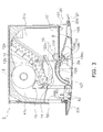
- FIG. 3 is a cross-sectional view of the air conditioning indoor unit.
- the air conditioning indoor unit 2 is further equipped with filters 9, a filter cleaning mechanism 10, an indoor heat exchanger 12, an indoor fan 13, a drain pan 14, and a blowout port module 50.
- the suction port 20a and the blowout port 20b open, the indoor fan 13 rotates, and air is sucked in from the suction port 20a.
- the indoor heat exchanger 12 has a shape where two heat exchangers are adjacent in different slanting postures; for convenience of description, the heat exchanger on the upper side will be called an upper heat exchanger 12a and the heat exchanger on the lower side will be called a lower heat exchanger 12b.
- the upper end of the upper heat exchanger 12a is positioned in the upper portion of the inside of the body 20, and the angle at which the upper heat exchanger 12a slants from its upper end toward its lower end is set to be equal to or greater than 45° and equal to or less than 60° (and preferably 55°) with respect to a horizontal line, so that condensation water reliably travels through the upper heat exchanger 12a toward the drain pan 14. For this reason, it is not necessary for the drain pan 14 to be placed below the entire upper heat exchanger 12a, and the drain pan 14 is placed only below the neighborhood of the lower end of the upper heat exchanger 12a.
- the upper end of the lower heat exchanger 12b is placed in proximity to the lower end of the upper heat exchanger 12a, and the angle at which the lower heat exchanger 12b slants from its upper end toward its lower end is less than 45° with respect to a horizontal line. For this reason, there is the potential for condensation water to fall directly therefrom, so the drain pan 14 is placed below the entire lower heat exchanger 12b.
- the indoor fan 13 is a cross-flow fan, has a width dimension that is longer than its diameter, and sucks in air from a direction perpendicular to its axis of rotation, so the indoor fan 13 can suck in air from the single suction port 20a and blow out air to the single blowout port 20b.
- the air that has been sucked in passes through the filters 9 and the indoor heat exchanger 12 and enters the indoor fan 13.
- the air that has been blown out from the indoor fan 13 passes through the blowout port module 50 and is blown out from the blowout port 20b.
- the first blowing direction adjusting blade 52 that is a component of the blowout port module 50; the angle of inclination of the first blowing direction adjusting blade 52 is adjustable by a motor, and at the time when operation is stopped, the first blowing direction adjusting blade 52 closes the blowout port 20b.
- a tongue portion 15 Between the indoor fan 13 and the drain pan 14 and on a blowout flow path 41 a side, there is disposed a tongue portion 15, and this tongue portion 15 prevents leakage of the blowout air and improves performance.
- the air conditioning indoor unit 2 is equipped with the filter cleaning mechanism 10 above the movable panel 24.
- the configural members of the filter cleaning mechanism 10 will be described below.
- the filters 9 are placed on the front surface side of the indoor heat exchanger 12 and remove dust from the air that has been taken in from the indoors. Thus, the filters 9 prevent dust floating in the air from contaminating the surface of the indoor heat exchanger 12. In edge portions of the filters 9, there are formed racks 101 that mesh with pinion gears 102a.
- a roller 102 has the pinion gears 102a.
- the pinion gears 102a mesh with the racks 101 of the filters 9 and rotate to thereby cause the filters 9 to move horizontally.
- the positions where the filters 9 stop are detected by position detection switches 107.
- the position detection switches 107 are placed in the neighborhood of the terminal end of a front housing portion 105 and in the neighborhood of the terminal end of a rear housing portion 106.
- levers are mounted by hinges, and when external force is applied, the levers rotate and push buttons of the position detection switches 107.
- a brush 108 is positioned on the opposite side of the roller 102 across the filters 9 and touches the filters 9
- a dust box 109 has a dust intake port 109a in its upper portion on the side toward the blowout port 20b and supports a rotating shaft of the brush 108 via bearings on both ends in the lengthwise direction of the dust intake port. Moreover, a comb portion 109c that knocks the dust that the brush 108 has scraped off of the filters 9 off of the brush 108 is attached to the dust intake port.
- the filters 9 are automatically cleaned periodically by a control unit or by a remote controller when the user deems it necessary. The mechanism thereof will be described below.
- the racks 101 of the filters 9 fit in the front housing portion 105, and one end of each of the racks 101 (hereinafter called first end portions) meshes with the pinion gears 102a.
- first end portions meshes with the pinion gears 102a.
- the roller 102 rotates, the rotation is transmitted from the pinion gears 102a to the racks 101, and the racks 101 of the filters 9 are conveyed toward the rear housing portion 106 by the roller 102.
- the roller 102 continues rotating, whereby the first end portions of the racks 101 reach the terminal end of the rear housing portion 106.
- the brush 108 rotates at least during the period when the filters 9 are moving from the front housing portion 105 to the rear housing portion 106, and the direction of rotation thereof is a direction counter to the traveling direction of the filters 9.
- the control unit causes the roller 102 to reversely rotate.
- the other end portions (hereinafter called second end portions) of the racks 101 of the filters 9 mesh with the pinion gears 102a, so the rotation is transmitted from the pinion gears 102a to the racks 101 and the filters 9 are conveyed toward the front housing portion 105 by the roller 102.
- the roller 102 continues reversely rotating, whereby the second end portions of the racks 101 reach the terminal end of the front housing portion 105.
- FIG. 4 is a perspective view of the ornamental panel. As shown in FIG. 4 , on the surface on the ceiling side of the ornamental panel 21, there are placed hinge coupling devices 6 and the raising-and-lowering devices 7.
- the hinge coupling devices 6 rotatably support one end of the movable panel 24 when the air conditioning indoor unit 2 runs and release the support of the one end of the movable panel 24 when the movable panel 24 is lowered to the maintenance position.
- FIG. 5 is an exploded perspective diagram of the hinge coupling devices.
- each of the hinge coupling devices 6 has a rotating lever 61, a slide member 62, a first pin 63, a pinion gear 64, a motor 65, a fixing member 66, a second pin 67, and screws 68.
- the rotating lever 61 is a U-shaped member, and a rod-shaped support shaft 6 la projects outward from an end surface.
- a shaft hole 61b is formed in one end portion of the rotating lever 61.
- the slide member 62 there are formed a rack 62a that meshes with the pinion gear 64 and arms 62b that sandwich both ends of the shaft hole 61b in the rotating lever 61. Moreover, in the arms 62b, there is formed a first slide hole 62c, and in the neighborhood of the base of the rack 62a, there is formed a second slide hole 62d.
- the motor 65 is a stepping motor and causes the pinion gear 64 to rotate.
- the motor 65 has through holes 65a through which the screws 68 pass.
- a slide space 66a that slidably holds the slide member 62, a gear space 66b into which the pinion gear 64 is inserted, and screw holes 66c into which the screws 68 are screwed.
- a first through hole 66d and a second through hole 66e are formed in the walls that form the slide space 66a.
- the slide member 62 is placed in the slide space 66a in the fixing member 66, and the rotating lever 61 is placed in the slide member 62 such that the shaft hole 6 1 b in the rotating lever 61 is sandwiched between the arms 62b of the slide member 62.
- the first pin 63 is inserted from one end of the first through hole 66d in the fixing member 66, passes through the first slide hole 62c in the slide member 62 and the shaft hole 61b in the rotating lever 61, and reaches the other end of the first through hole 66d.
- the second pin 67 is inserted from one end of the second through hole 66e, passes through the second slide hole 62d in the slide member 62, and reaches the other end of the second through hole 66e.
- the slide member 62 can move horizontally in the slide space along the first pin 63 and the second pin 67, and the rotating lever 61 can rotate about the first pin 63.
- the movable panel 24 In the end portion of the movable panel 24, there are disposed support holes that confront the support shafts 61 a of the rotating levers 61, and when the motors 65 forwardly rotate such that the support shafts 61a are inserted in the support holes in the movable panel 24, coupling between the rotating levers 61 and the movable panel 24 becomes established, and the movable panel 24 can rotate about the first pins 63.
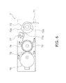
- FIG. 6 is a view of the layout of parts inside each of the raising-and-lowering devices.
- each of the raising-and-lowering devices 7 has a wire 71, a pulley 72, a bobbin 73, a take-up gear 74, a drive gear 75, a raising-and-lowering motor 76, and a switch 77.
- the pulley 72 comprises a pulley portion 72a and a cam portion 72b that are integrally molded, and the pulley portion 72a supports the wire 71 and rotates in accompaniment with the movement of the wire 71.
- the cam portion 72b comprises a small diameter curved surface, a large diameter curved surface, and a flat surface that interconnects both of those curved surfaces.
- the bobbin 73 takes up the wire 71.
- the take-up gear 74 is coaxially coupled to and integrally rotates with the bobbin 73.
- the drive gear 75 meshes with the take-up gear 74 and causes the bobbin 73 to rotate.
- the raising-and-lowering motor 76 is a stepping motor and causes the drive gear 75 to rotate.
- the speed of the raising-and-lowering motor 76 is controlled by a number of pulses supplied from the control unit.
- the control unit has a built-in CPU, memory, and motor drive circuit and is placed in another position away from the raising-and-lowering device 7.
- the control unit is electrically connected to the raising-and-lowering motor 76 by a wire harness.
- the switch 77 is a micro switch having a lever 77a and is switched ON as a result of the lever 77a being pushed.
- the lever 77a always touches the cam portion 72b of the pulley 72 and is pushed when it confronts the large diameter curved surface of the cam portion 72b.
- the switch 77 is also electrically connected to the control unit by a wire harness.
- the raising-and-lowering motors 76 cause the drive gears 75 to rotate in direction CW and cause the take-up gears 74 to rotate in direction CCW.
- the bobbins 73 rotate in the direction where they take up the wires 71.
- the let-out amount and the take-up amount of the wires are proportional to the amount of rotation of the raising-and-lowering motors 76, and the let-out amount and the take-up amount of the wires 71 are controlled as a result of the control unit controlling the number of pulses it supplies to the raising-and-lowering motors 76.
- the movable panel 24 is coupled to the distal ends of the wires 71, so there is always tension in the wires 71, and when the wires 71 are let out or when the wires 71 are taken up, the pulley portions 72a rotate because of frictional force with the wires 71.
- the cam portions 72b also rotate, so the switches 77 issue ON signals when the levers 77a confront the large diameter curved surfaces of the cam portions 72b and issue OFF signals when the levers 77a confront the small diameter curved surfaces. While the pulleys 72 are rotating, the ON signals and the OFF signals are alternately generated, and these signals are all inputted to the control unit.
- FIG. 7 is a partial cross-sectional view of the air conditioning indoor unit when the movable panel has opened the suction opening.
- the movable panel 24 descends because of its own weight. However, because the end portion of the movable panel 24 is coupled to the hinge coupling devices 6, the movable panel 24 rotates about the first pins 63 in the direction where it opens the suction opening 20a.
- the first pins 63 are position in the space sandwiched between the suction port 20a and the blowout port 20b in the body 20, and the end portion of the movable panel 24 that is nearest to the body 20 rotates while drawing a large circular arc, so the movable panel 24 does not interfere with the peripheral edge of the suction port 20a.
- the surface of the movable panel 24 on the side near the center of rotation is configured as a slanted surface 24d and slanted upward away from the center of rotation, so when the movable panel 24 rotates, the movable panel 24 does not interfere with the peripheral edge of the suction port 20a.
- the design of the air conditioning indoor unit 2 improves.
- the movable panel 24 When the raising-and-lowering devices 7 take up the wires 71, the movable panel 24 ascends, but because the end portion of the movable panel 24 is coupled to the hinge coupling devices 6, the movable panel 24 rotates about the first pins 63 in the direction where it closes the suction port 20a.
- the first pins 63 that are center-of-rotation shafts of the movable panel 24 are placed in a position away from the neighborhood of the boundary between the body 20 and the movable panel 24.
- the movable panel 24 opens the suction port 20a
- the movable panel 24 opens the suction port 20a while widening the clearance between the body 20 and the movable panel 24, so the body 20 and the movable panel 24 do not interfere with each other.
- the clearance at the boundary between the body 20 and the movable panel 24 when the movable panel 24 is closing the suction port 20a becomes set small, and the design improves.
- the movable panel 24 and the first pins 63 are coupled together by the rotating levers 61, but the rotating levers 61 and the movable panel 24 are detachable. In other words, it is not necessary for the first pins 63, the rotating levers 61, and the movable body 24 to be integrated, so the degree of freedom of design increases.
- the present invention is useful in an air conditioning indoor unit that rotatably supports, with a hinge system in the neighborhood of a suction port, a movable panel capable of being raised and lowered and which closes the suction port at a time when operation is stopped.
Landscapes
- Engineering & Computer Science (AREA)
- Chemical & Material Sciences (AREA)
- Combustion & Propulsion (AREA)
- Mechanical Engineering (AREA)
- General Engineering & Computer Science (AREA)
- Air Filters, Heat-Exchange Apparatuses, And Housings Of Air-Conditioning Units (AREA)
- Air-Flow Control Members (AREA)
Abstract
Description
- The present invention relates to a ceiling-mounted air conditioning indoor unit.
- Conventionally, as a ceiling-mounted air conditioning indoor unit, an air conditioning indoor unit that closes an opening in an ornamental panel with a movable panel capable of being raised and lowered has been widely known (e.g., see patent document 1). In that air conditioning indoor unit, the movable panel is hoisted by wires, the movable panel descends as a result of raising-and-lowering devices letting out those wires, and the movable panel ascends as a result of the raising-and-lowering devices taking up those wires.
- The movable panel descends at a time of maintenance of filters, and the movable panel ascends and closes the opening at a time of operation and at a time of shutdown. In other words, the opening completely opens only at the time of maintenance of the filters, and in a usual state, the opening leaves a suction port on both sides and is always closed. In this air conditioning indoor unit, the suction port is always open, and the filters and the inside of the indoor unit are exposed through that suction port, so the design remarkably drops.
- Thus, the applicant conducted a study of an air conditioning indoor unit that rotatably supports, with a hinge system in the neighborhood of the suction port, a movable panel capable of being raised and lowered and closes the suction port at a time when operation is stopped. However, the applicant found that in order to prevent interference with the periphery of the suction port when the movable panel opens the suction port while rotating, the clearance between the movable panel and the periphery of the suction port becomes set wide, and conversely that clearance lowers the design.
Patent Document 1:JP-ANo. 10-196999 - It is an object of the present invention to provide, in an air conditioning indoor unit that rotatably supports a movable panel with a hinge system in the neighborhood of a suction port, an air conditioning indoor unit that is capable of setting the clearance between the movable panel and the periphery of the suction port small.
- An air conditioning indoor unit pertaining to a first aspect of the present invention is a ceiling-mounted air conditioning indoor unit comprising a body that has an opening in its undersurface and a movable panel that opens and closes the opening by rotating. A center-of-rotation shaft of the movable panel is placed in a position away from the neighborhood of the boundary between the body and the movable panel.
- In this air conditioning indoor unit, when the movable panel opens the opening, the movable panel opens the opening while widening the clearance between the body and the movable panel, so the body and the movable panel do not interfere with each other. As a result, the clearance between the body and the movable panel when the movable panel is closing the opening becomes set small, and the design improves.
- An air conditioning indoor unit pertaining to a second aspect of the present invention is the air conditioning indoor unit pertaining to the first aspect of the present invention, further comprising a lever that is detachably mounted on the movable panel and couples together the movable panel and the center-of-rotation shaft. In this air conditioning indoor unit, it is not necessary for the center-of-rotation shaft, the lever, and the movable panel to be integrated, so the degree of freedom with which the center-of-rotation shaft and the lever may be designed increases.
- An air conditioning indoor unit pertaining to a third aspect of the present invention is the air conditioning indoor unit pertaining to the first aspect or the second aspect of the present invention, wherein the movable panel has a slanted portion in a portion adjacent to the body.
- In this air conditioning indoor unit, the clearance between the body and the movable panel when the movable panel is closing the opening is set such that the body and the movable panel do not interfere with each other when the movable panel opens the opening, and with a movable panel that has a slanted portion, the clearance is set smaller in comparison to a movable panel that does not have a slanted portion. As a result, the design improves.
- An air conditioning indoor unit pertaining to a fourth aspect of the present invention is the air conditioning indoor unit pertaining to any one of the first aspect to the third aspect of the present invention, wherein when the movable panel opens the opening, the portion of the movable panel with the shortest moving distance moves below the portion that had been the boundary between the body and the movable panel when the movable panel had closed the opening.
- In this air conditioning indoor unit, when the movable panel opens the opening, the movable panel covers part of the peripheral edge of the opening, so the clearance when seen from below is hidden, and the design improves.
- An air conditioning indoor unit pertaining to a fifth aspect of the present invention is the air conditioning indoor unit pertaining to any one of the first aspect to the fourth aspect of the present invention, wherein the opening is a suction port for sucking in air. In this air conditioning indoor unit, the clearance between the body and the movable panel when the movable panel is closing the suction opening becomes set small, and the design improves.
- In the air conditioning indoor unit pertaining to the first aspect of the present invention, the clearance between the body and the movable panel when the movable panel is closing the opening becomes set small, and the design improves.
- In the air conditioning indoor unit pertaining to the second aspect of the present invention, it is not necessary for the center-of-rotation shaft, the lever, and the movable panel to be integrated, so the degree of freedom with which the center-of-rotation shaft and the lever may be designed increases.
- In the air conditioning indoor unit pertaining to the third aspect of the present invention, the slanted portion is disposed such that the body and the movable panel do not interfere with each other when the movable panel opens the opening, so the clearance between the body and the movable panel is set small and the design is good in comparison to a movable panel that does not have a slanted portion.
- In the air conditioning indoor unit pertaining to the fourth aspect of the present invention, when the movable panel opens the opening, the movable panel covers part of the peripheral edge of the opening, so the clearance when seen from below is hidden, and the design improves.
- In the air conditioning indoor unit pertaining to the fifth aspect of the present invention, the clearance between the body and the movable panel when the movable panel is closing the suction opening becomes set small, and the design improves.
-
-
FIG. 1 is an exterior perspective view of an air conditioning indoor unit pertaining to an embodiment of the present invention. -
FIG. 2(a) is a side view of the air conditioning indoor unit at a time when operation is stopped,FIG. 2(b) is a side view of the air conditioning indoor unit at a time of operation, andFIG. 2(c) is a side view of the air conditioning indoor unit at a time of maintenance. -
FIG. 3 is a cross-sectional view of the air conditioning indoor unit. -
FIG. 4 is a perspective view of an ornamental panel. -
FIG. 5 is an exploded perspective view of a hinge coupling device. -
FIG. 6 is a view of the layout of parts inside a raising-and-lowering device. -
FIG. 7 is a partial cross-sectional view of the air conditioning indoor unit when a movable panel has opened a suction port. -
- 2
- Air Conditioning Indoor Unit
- 20
- Body
- 20a
- Suction Port
- 24
- Movable Panel
- 24d
- Slanted Surface
- 61
- Rotating Levers
- 63
- First Pins (Center-of-Rotation Shafts)
- An embodiment of the present invention will be described below with reference to the drawings. The embodiment below is a specific example of the present invention and is not intended to limit the technical scope of the present invention.
-
-
FIG. 1 is an exterior perspective view of an air conditioning indoor unit pertaining to the embodiment of the present invention. InFIG. 1 , an air conditioningindoor unit 2 is equipped with abody 20 that has asuction port 20a and ablowout port 20b in its undersurface, amovable panel 24 that opens and closes thesuction port 20a, and a first blowingdirection adjusting blade 52 that opens and closes theblowout port 20b. Thesuction port 20a and theblowout port 20b are adjacent but spaced a certain distance apart from each other to ensure that so-called short-circuiting-or a phenomenon where air that has been blown out from theblowout port 20b is sucked back into thesuction port 20a-does not occur. The undersurface of thebody 20 is covered by anornamental panel 21 so that what is actually exposed to the ceiling surface is theornamental panel 21, and the outlines of thesuction port 20a and theblowout port 20b are formed by theornamental panel 21. Here, theornamental panel 21 is also included in thebody 20. -
FIG. 2(a) is a side view of the air conditioning indoor unit at a time when operation is stopped,FIG. 2(b) is a side view of the air conditioning indoor unit at a time of operation, andFIG. 2(c) is a side view of the air conditioning indoor unit at a time of maintenance. InFIGS. 2(a), 2(b), and 2(c) , when the air conditioningindoor unit 2 is stopped, themovable panel 24 looks as if it is integrated with theornamental panel 21. InFIG. 2(b) , when the air conditioningindoor unit 2 runs, themovable panel 24 opens thesuction port 20a, and the first blowingdirection adjusting blade 52 opens theblowout port 20b. One end of themovable panel 24 is supported on thebody 20 by hinges, and themovable panel 24 rotates and opens thesuction port 20a. - Further, in
FIG. 2(c) , themovable panel 24 can descend to a maintenance position that the user can reach by hand in a state where themovable panel 24 is hung onwires 71 extending from thebody 20. However, themovable panel 24 cannot descend to the maintenance position in a state where its one end is being supported on thebody 20 by the hinges, so themovable panel 24 first closes thesuction port 20a and then descends to the maintenance position after the support by thebody 20 has been released. -
FIG. 3 is a cross-sectional view of the air conditioning indoor unit. InFIG. 3 , the air conditioningindoor unit 2 is further equipped with filters 9, afilter cleaning mechanism 10, anindoor heat exchanger 12, anindoor fan 13, adrain pan 14, and ablowout port module 50. At the time of operation of the air conditioningindoor unit 2, thesuction port 20a and theblowout port 20b open, theindoor fan 13 rotates, and air is sucked in from thesuction port 20a. - The
indoor heat exchanger 12 has a shape where two heat exchangers are adjacent in different slanting postures; for convenience of description, the heat exchanger on the upper side will be called anupper heat exchanger 12a and the heat exchanger on the lower side will be called alower heat exchanger 12b. - The upper end of the
upper heat exchanger 12a is positioned in the upper portion of the inside of thebody 20, and the angle at which theupper heat exchanger 12a slants from its upper end toward its lower end is set to be equal to or greater than 45° and equal to or less than 60° (and preferably 55°) with respect to a horizontal line, so that condensation water reliably travels through theupper heat exchanger 12a toward thedrain pan 14. For this reason, it is not necessary for thedrain pan 14 to be placed below the entireupper heat exchanger 12a, and thedrain pan 14 is placed only below the neighborhood of the lower end of theupper heat exchanger 12a. - The upper end of the
lower heat exchanger 12b is placed in proximity to the lower end of theupper heat exchanger 12a, and the angle at which thelower heat exchanger 12b slants from its upper end toward its lower end is less than 45° with respect to a horizontal line. For this reason, there is the potential for condensation water to fall directly therefrom, so thedrain pan 14 is placed below the entirelower heat exchanger 12b. - The
indoor fan 13 is a cross-flow fan, has a width dimension that is longer than its diameter, and sucks in air from a direction perpendicular to its axis of rotation, so theindoor fan 13 can suck in air from thesingle suction port 20a and blow out air to thesingle blowout port 20b. The air that has been sucked in passes through the filters 9 and theindoor heat exchanger 12 and enters theindoor fan 13. - The air that has been blown out from the
indoor fan 13 passes through theblowout port module 50 and is blown out from theblowout port 20b. In theblowout port 20b, there is placed the first blowingdirection adjusting blade 52 that is a component of theblowout port module 50; the angle of inclination of the first blowingdirection adjusting blade 52 is adjustable by a motor, and at the time when operation is stopped, the first blowingdirection adjusting blade 52 closes theblowout port 20b. Between theindoor fan 13 and thedrain pan 14 and on ablowout flow path 41 a side, there is disposed atongue portion 15, and thistongue portion 15 prevents leakage of the blowout air and improves performance. - As shown in
FIG. 3 , the air conditioningindoor unit 2 is equipped with thefilter cleaning mechanism 10 above themovable panel 24. The configural members of thefilter cleaning mechanism 10 will be described below. - The filters 9 are placed on the front surface side of the
indoor heat exchanger 12 and remove dust from the air that has been taken in from the indoors. Thus, the filters 9 prevent dust floating in the air from contaminating the surface of theindoor heat exchanger 12. In edge portions of the filters 9, there are formedracks 101 that mesh withpinion gears 102a. - A
roller 102 has the pinion gears 102a. The pinion gears 102a mesh with theracks 101 of the filters 9 and rotate to thereby cause the filters 9 to move horizontally. - The positions where the filters 9 stop are detected by position detection switches 107. The position detection switches 107 are placed in the neighborhood of the terminal end of a
front housing portion 105 and in the neighborhood of the terminal end of arear housing portion 106. On the outer sides of the position detection switches 107, levers are mounted by hinges, and when external force is applied, the levers rotate and push buttons of the position detection switches 107. - A
brush 108 is positioned on the opposite side of theroller 102 across the filters 9 and touches the filters 9 Adust box 109 has a dust intake port 109a in its upper portion on the side toward theblowout port 20b and supports a rotating shaft of thebrush 108 via bearings on both ends in the lengthwise direction of the dust intake port. Moreover, acomb portion 109c that knocks the dust that thebrush 108 has scraped off of the filters 9 off of thebrush 108 is attached to the dust intake port. - In the air conditioning
indoor unit 2, the filters 9 are automatically cleaned periodically by a control unit or by a remote controller when the user deems it necessary. The mechanism thereof will be described below. - In
FIG. 3 , theracks 101 of the filters 9 fit in thefront housing portion 105, and one end of each of the racks 101 (hereinafter called first end portions) meshes with the pinion gears 102a. When theroller 102 rotates, the rotation is transmitted from the pinion gears 102a to theracks 101, and theracks 101 of the filters 9 are conveyed toward therear housing portion 106 by theroller 102. Theroller 102 continues rotating, whereby the first end portions of theracks 101 reach the terminal end of therear housing portion 106. - When the filters 9 move, the dust that had adhered to the surfaces of the filters 9 is scraped off by the
brush 108 and collected in thedust box 109. Thebrush 108 rotates at least during the period when the filters 9 are moving from thefront housing portion 105 to therear housing portion 106, and the direction of rotation thereof is a direction counter to the traveling direction of the filters 9. - When the filters 9 move from the
front housing portion 105 to therear housing portion 106 and removal of the dust ends, the control unit causes theroller 102 to reversely rotate. The other end portions (hereinafter called second end portions) of theracks 101 of the filters 9 mesh with the pinion gears 102a, so the rotation is transmitted from the pinion gears 102a to theracks 101 and the filters 9 are conveyed toward thefront housing portion 105 by theroller 102. Theroller 102 continues reversely rotating, whereby the second end portions of theracks 101 reach the terminal end of thefront housing portion 105. -
FIG. 4 is a perspective view of the ornamental panel. As shown inFIG. 4 , on the surface on the ceiling side of theornamental panel 21, there are placedhinge coupling devices 6 and the raising-and-loweringdevices 7. - The
hinge coupling devices 6 rotatably support one end of themovable panel 24 when the air conditioningindoor unit 2 runs and release the support of the one end of themovable panel 24 when themovable panel 24 is lowered to the maintenance position. -
FIG. 5 is an exploded perspective diagram of the hinge coupling devices. InFIG. 5 , each of thehinge coupling devices 6 has arotating lever 61, aslide member 62, afirst pin 63, apinion gear 64, amotor 65, a fixingmember 66, asecond pin 67, and screws 68. The rotatinglever 61 is a U-shaped member, and a rod-shapedsupport shaft 6 la projects outward from an end surface. Moreover, ashaft hole 61b is formed in one end portion of therotating lever 61. - In the
slide member 62, there are formed arack 62a that meshes with thepinion gear 64 andarms 62b that sandwich both ends of theshaft hole 61b in therotating lever 61. Moreover, in thearms 62b, there is formed afirst slide hole 62c, and in the neighborhood of the base of therack 62a, there is formed asecond slide hole 62d. Themotor 65 is a stepping motor and causes thepinion gear 64 to rotate. Themotor 65 has throughholes 65a through which thescrews 68 pass. - In the fixing
member 66, there are formed aslide space 66a that slidably holds theslide member 62, agear space 66b into which thepinion gear 64 is inserted, and screwholes 66c into which thescrews 68 are screwed. Moreover, in the walls that form theslide space 66a, there are formed a first throughhole 66d and a second throughhole 66e. - The
slide member 62 is placed in theslide space 66a in the fixingmember 66, and therotating lever 61 is placed in theslide member 62 such that theshaft hole 6 1 b in therotating lever 61 is sandwiched between thearms 62b of theslide member 62. Thefirst pin 63 is inserted from one end of the first throughhole 66d in the fixingmember 66, passes through thefirst slide hole 62c in theslide member 62 and theshaft hole 61b in therotating lever 61, and reaches the other end of the first throughhole 66d. - The
second pin 67 is inserted from one end of the second throughhole 66e, passes through thesecond slide hole 62d in theslide member 62, and reaches the other end of the second throughhole 66e. As a result, theslide member 62 can move horizontally in the slide space along thefirst pin 63 and thesecond pin 67, and therotating lever 61 can rotate about thefirst pin 63. - In
FIG. 4 andFIG. 5 , when themotors 65 cause the pinion gears 64 to rotate, motive force is transmitted to theracks 62a meshing with the pinion gears 64, theslide members 62 slide along thefirst pins 63, and therotating levers 61 move in the direction of themovable panel 24 or in the opposite direction in accompaniment with the movement of theslide members 62. Here, for convenience of description, rotation of themotors 65 to move therotating levers 61 in the direction where therotating levers 61 become coupled to themovable panel 24 will be called forward rotation, and rotation of themotors 65 to move therotating levers 61 in the direction where the coupling between therotating levers 61 and themovable panel 24 becomes released will be called reverse rotation. - In the end portion of the
movable panel 24, there are disposed support holes that confront thesupport shafts 61 a of therotating levers 61, and when themotors 65 forwardly rotate such that thesupport shafts 61a are inserted in the support holes in themovable panel 24, coupling between therotating levers 61 and themovable panel 24 becomes established, and themovable panel 24 can rotate about the first pins 63. - On the other hand, when the
motor 65 reversely rotates such that thesupport shafts 61a come out of the support holes in themovable panel 24, the coupling between therotating levers 61 and themovable panel 24 is released, and themovable panel 24 cannot rotate about the first pins 63. -
FIG. 6 is a view of the layout of parts inside each of the raising-and-lowering devices. InFIG. 6 , each of the raising-and-loweringdevices 7 has awire 71, apulley 72, abobbin 73, a take-up gear 74, a drive gear 75, a raising-and-loweringmotor 76, and aswitch 77. - The
pulley 72 comprises apulley portion 72a and acam portion 72b that are integrally molded, and thepulley portion 72a supports thewire 71 and rotates in accompaniment with the movement of thewire 71. Thecam portion 72b comprises a small diameter curved surface, a large diameter curved surface, and a flat surface that interconnects both of those curved surfaces. - The
bobbin 73 takes up thewire 71. The take-up gear 74 is coaxially coupled to and integrally rotates with thebobbin 73. The drive gear 75 meshes with the take-up gear 74 and causes thebobbin 73 to rotate. - The raising-and-lowering
motor 76 is a stepping motor and causes the drive gear 75 to rotate. The speed of the raising-and-loweringmotor 76 is controlled by a number of pulses supplied from the control unit. The control unit has a built-in CPU, memory, and motor drive circuit and is placed in another position away from the raising-and-loweringdevice 7. The control unit is electrically connected to the raising-and-loweringmotor 76 by a wire harness. - The
switch 77 is a micro switch having alever 77a and is switched ON as a result of thelever 77a being pushed. Thelever 77a always touches thecam portion 72b of thepulley 72 and is pushed when it confronts the large diameter curved surface of thecam portion 72b. Theswitch 77 is also electrically connected to the control unit by a wire harness. - In
FIG. 6 , when the raising-and-loweringdevices 7 let out thewires 71, the raising-and-lowenngmotors 76 cause the drive gears 75 to rotate in direction CCW and cause the take-up gears 74 to rotate in direction CW. Thus, thebobbins 73 rotate in the direction where they let out thewires 71. - On the other hand, when the raising-and-lowering
devices 7 take up thewires 71, the raising-and-loweringmotors 76 cause the drive gears 75 to rotate in direction CW and cause the take-up gears 74 to rotate in direction CCW. Thus, thebobbins 73 rotate in the direction where they take up thewires 71. The let-out amount and the take-up amount of the wires are proportional to the amount of rotation of the raising-and-loweringmotors 76, and the let-out amount and the take-up amount of thewires 71 are controlled as a result of the control unit controlling the number of pulses it supplies to the raising-and-loweringmotors 76. - The
movable panel 24 is coupled to the distal ends of thewires 71, so there is always tension in thewires 71, and when thewires 71 are let out or when thewires 71 are taken up, thepulley portions 72a rotate because of frictional force with thewires 71. At this time, thecam portions 72b also rotate, so theswitches 77 issue ON signals when thelevers 77a confront the large diameter curved surfaces of thecam portions 72b and issue OFF signals when thelevers 77a confront the small diameter curved surfaces. While thepulleys 72 are rotating, the ON signals and the OFF signals are alternately generated, and these signals are all inputted to the control unit. -
FIG. 7 is a partial cross-sectional view of the air conditioning indoor unit when the movable panel has opened the suction opening. InFIG. 7 , when the raising-and-loweringdevices 7 let out thewires 71 in a state where thehinge coupling devices 6 couple themovable panel 24, themovable panel 24 descends because of its own weight. However, because the end portion of themovable panel 24 is coupled to thehinge coupling devices 6, themovable panel 24 rotates about thefirst pins 63 in the direction where it opens thesuction opening 20a. - The first pins 63 are position in the space sandwiched between the
suction port 20a and theblowout port 20b in thebody 20, and the end portion of themovable panel 24 that is nearest to thebody 20 rotates while drawing a large circular arc, so themovable panel 24 does not interfere with the peripheral edge of thesuction port 20a. Further, the surface of themovable panel 24 on the side near the center of rotation is configured as aslanted surface 24d and slanted upward away from the center of rotation, so when themovable panel 24 rotates, themovable panel 24 does not interfere with the peripheral edge of thesuction port 20a. - Further, when the
movable panel 24 opens thesuction port 20a, the portion of themovable panel 24 with the shortest moving distance-that is, the undersurface edge on the side near the center of rotation of the movable panel 24-moves below the portion that had been the boundary between thebody 20 and themovable panel 24 when themovable panel 24 had closed thesuction port 20a, so the clearance at the boundary between thebody 20 and themovable panel 24 when seen from below is hidden. As a result, the design of the air conditioningindoor unit 2 improves. - When the raising-and-lowering
devices 7 take up thewires 71, themovable panel 24 ascends, but because the end portion of themovable panel 24 is coupled to thehinge coupling devices 6, themovable panel 24 rotates about thefirst pins 63 in the direction where it closes thesuction port 20a. - When the
hinge coupling devices 6 release their coupling with themovable panel 24 and the raising-and-loweringdevices 7 let out thewires 71, themovable panel 24 descends because of its own weight. When the raising-and-loweringdevices 7 take up thewires 71, themovable panel 24 ascends and closes thesuction port 20a. - In the air conditioning
indoor unit 2, thefirst pins 63 that are center-of-rotation shafts of themovable panel 24 are placed in a position away from the neighborhood of the boundary between thebody 20 and themovable panel 24. When themovable panel 24 opens thesuction port 20a, themovable panel 24 opens thesuction port 20a while widening the clearance between thebody 20 and themovable panel 24, so thebody 20 and themovable panel 24 do not interfere with each other. As a result, the clearance at the boundary between thebody 20 and themovable panel 24 when themovable panel 24 is closing thesuction port 20a becomes set small, and the design improves. - The
movable panel 24 and thefirst pins 63 are coupled together by the rotatinglevers 61, but therotating levers 61 and themovable panel 24 are detachable. In other words, it is not necessary for thefirst pins 63, the rotatinglevers 61, and themovable body 24 to be integrated, so the degree of freedom of design increases. - As described above, the present invention is useful in an air conditioning indoor unit that rotatably supports, with a hinge system in the neighborhood of a suction port, a movable panel capable of being raised and lowered and which closes the suction port at a time when operation is stopped.
Claims (5)
- A ceiling-mounted air conditioning indoor unit (2) comprising:a body (20) that has an opening (20a) in its undersurface; anda movable panel (24) that opens and closes the opening (20a) by rotating,wherein a center-of-rotation shaft (63) of the movable panel (24) is placed in a position away from the neighborhood of the boundary between the body (20) and the movable panel (24).
- The air conditioning indoor unit (2) according to claim 1, further comprising a lever (61) that is detachably mounted on the movable panel (24) and couples together the movable panel (24) and the center-of-rotation shaft (63).
- The air conditioning indoor unit (2) according to claim 1 or claim 2, wherein the movable panel (24) has a slanted portion (24d) in a portion adjacent to the body (20).
- The air conditioning indoor unit (2) according to any one of claim 1 to claim 3, wherein when the movable panel (24) opens the opening (20a), the portion of the movable panel (24) with the shortest moving distance moves below the portion that had been the boundary between the body (20) and the movable panel (24) when the movable panel (24) had closed the opening (20a).
- The air conditioning indoor unit (2) according to any one of claim 1 to claim 4, wherein the opening (20a) is a suction port for sucking in air.
Applications Claiming Priority (3)
| Application Number | Priority Date | Filing Date | Title |
|---|---|---|---|
| JP2008025651 | 2008-02-05 | ||
| JP2008186409A JP4433076B2 (en) | 2008-02-05 | 2008-07-17 | Air conditioning indoor unit |
| PCT/JP2009/000206 WO2009098837A1 (en) | 2008-02-05 | 2009-01-21 | Air-conditioning indoor equipment |
Publications (3)
| Publication Number | Publication Date |
|---|---|
| EP2251617A1 true EP2251617A1 (en) | 2010-11-17 |
| EP2251617A4 EP2251617A4 (en) | 2013-05-01 |
| EP2251617B1 EP2251617B1 (en) | 2017-03-22 |
Family
ID=40951918
Family Applications (1)
| Application Number | Title | Priority Date | Filing Date |
|---|---|---|---|
| EP09708312.5A Not-in-force EP2251617B1 (en) | 2008-02-05 | 2009-01-21 | Air-conditioning indoor equipment |
Country Status (5)
| Country | Link |
|---|---|
| EP (1) | EP2251617B1 (en) |
| JP (1) | JP4433076B2 (en) |
| CN (1) | CN101932888B (en) |
| ES (1) | ES2620369T3 (en) |
| WO (1) | WO2009098837A1 (en) |
Families Citing this family (3)
| Publication number | Priority date | Publication date | Assignee | Title |
|---|---|---|---|---|
| CN105588192B (en) * | 2015-06-09 | 2019-01-22 | 青岛海信日立空调系统有限公司 | A built-in air conditioner indoor unit |
| CN108397822B (en) * | 2018-01-12 | 2019-12-31 | 青岛海尔空调器有限总公司 | Wall-mounted air conditioner indoor unit |
| MY189640A (en) * | 2018-05-14 | 2022-02-22 | Hitachi Johnson Controls Air Conditioning Inc | Air conditioner |
Family Cites Families (8)
| Publication number | Priority date | Publication date | Assignee | Title |
|---|---|---|---|---|
| JP2675695B2 (en) | 1991-07-18 | 1997-11-12 | 大日本スクリーン製造株式会社 | Light intensity control method for scanning beam |
| JP3306898B2 (en) * | 1992-03-26 | 2002-07-24 | 株式会社日立製作所 | Air conditioner |
| JPH0674552A (en) * | 1992-08-28 | 1994-03-15 | Toshiba Corp | Air-conditioner |
| PT768500E (en) * | 1995-10-13 | 2004-02-27 | Sanyo Electric Co | AIR SUCTION GRILL ELEVATION CONTROL DEVICE |
| JP3070470B2 (en) * | 1996-01-22 | 2000-07-31 | ダイキン工業株式会社 | Ceiling-mounted air conditioner |
| JP3816170B2 (en) | 1996-12-27 | 2006-08-30 | 小波株式会社 | Embedded ceiling air conditioner |
| JP3750298B2 (en) | 1997-08-20 | 2006-03-01 | 株式会社富士通ゼネラル | Recessed ceiling air conditioner |
| JP3950268B2 (en) * | 1999-08-30 | 2007-07-25 | 三菱重工業株式会社 | Embedded ceiling air conditioner |
-
2008
- 2008-07-17 JP JP2008186409A patent/JP4433076B2/en not_active Expired - Fee Related
-
2009
- 2009-01-21 EP EP09708312.5A patent/EP2251617B1/en not_active Not-in-force
- 2009-01-21 CN CN2009801040323A patent/CN101932888B/en not_active Expired - Fee Related
- 2009-01-21 WO PCT/JP2009/000206 patent/WO2009098837A1/en not_active Ceased
- 2009-01-21 ES ES09708312.5T patent/ES2620369T3/en active Active
Also Published As
| Publication number | Publication date |
|---|---|
| EP2251617A4 (en) | 2013-05-01 |
| JP2009210250A (en) | 2009-09-17 |
| WO2009098837A1 (en) | 2009-08-13 |
| JP4433076B2 (en) | 2010-03-17 |
| CN101932888B (en) | 2013-05-08 |
| ES2620369T3 (en) | 2017-06-28 |
| EP2251617B1 (en) | 2017-03-22 |
| CN101932888A (en) | 2010-12-29 |
Similar Documents
| Publication | Publication Date | Title |
|---|---|---|
| JP4821807B2 (en) | Air conditioning indoor unit | |
| EP2216608B1 (en) | Air conditioner | |
| US20090100851A1 (en) | Indoor unit of air conditioner | |
| KR20090090130A (en) | Air conditioner | |
| KR100776595B1 (en) | Air conditioner | |
| EP2251617B1 (en) | Air-conditioning indoor equipment | |
| KR20030017416A (en) | The Wall Type Air Washing System | |
| CN101676640B (en) | Air conditioner | |
| JP2009293807A (en) | Movable panel for air conditioner indoor unit | |
| JP5333022B2 (en) | Air conditioner indoor unit | |
| JP4561924B2 (en) | Ceiling-mounted air conditioner | |
| JP5493495B2 (en) | Air conditioner indoor unit | |
| JP4915392B2 (en) | Air conditioning indoor unit and method of moving panel of air conditioning indoor unit | |
| KR101450562B1 (en) | Air conditioner | |
| KR100557382B1 (en) | Wall Mounted Air Conditioner | |
| KR101450565B1 (en) | Air conditioner | |
| KR20060054075A (en) | Air conditioner | |
| JP4935774B2 (en) | Ceiling-mounted air conditioner | |
| KR100420527B1 (en) | The outlet closing apparatus of air-conditioner | |
| WO2010007906A1 (en) | Ceiling-mounted air conditioner | |
| JP5211865B2 (en) | Air-conditioning indoor unit movable panel | |
| JP5239629B2 (en) | Air conditioning indoor unit | |
| JP2010025415A (en) | Connecting structure and air conditioner comprising the same | |
| WO2007063737A1 (en) | Indoor unit for air conditioner | |
| KR20080056509A (en) | Air conditioner |
Legal Events
| Date | Code | Title | Description |
|---|---|---|---|
| PUAI | Public reference made under article 153(3) epc to a published international application that has entered the european phase |
Free format text: ORIGINAL CODE: 0009012 |
|
| 17P | Request for examination filed |
Effective date: 20100902 |
|
| AK | Designated contracting states |
Kind code of ref document: A1 Designated state(s): AT BE BG CH CY CZ DE DK EE ES FI FR GB GR HR HU IE IS IT LI LT LU LV MC MK MT NL NO PL PT RO SE SI SK TR |
|
| AX | Request for extension of the european patent |
Extension state: AL BA RS |
|
| DAX | Request for extension of the european patent (deleted) | ||
| A4 | Supplementary search report drawn up and despatched |
Effective date: 20130403 |
|
| RIC1 | Information provided on ipc code assigned before grant |
Ipc: F24F 13/08 20060101ALI20130326BHEP Ipc: F24F 13/28 20060101AFI20130326BHEP Ipc: F24F 13/20 20060101ALI20130326BHEP Ipc: F24F 1/00 20110101ALI20130326BHEP |
|
| GRAP | Despatch of communication of intention to grant a patent |
Free format text: ORIGINAL CODE: EPIDOSNIGR1 |
|
| RIC1 | Information provided on ipc code assigned before grant |
Ipc: F24F 1/00 20110101ALI20160922BHEP Ipc: F24F 13/20 20060101ALI20160922BHEP Ipc: F24F 13/08 20060101ALI20160922BHEP Ipc: F24F 13/28 20060101AFI20160922BHEP |
|
| INTG | Intention to grant announced |
Effective date: 20161010 |
|
| GRAS | Grant fee paid |
Free format text: ORIGINAL CODE: EPIDOSNIGR3 |
|
| STAA | Information on the status of an ep patent application or granted ep patent |
Free format text: STATUS: GRANT OF PATENT IS INTENDED |
|
| GRAA | (expected) grant |
Free format text: ORIGINAL CODE: 0009210 |
|
| STAA | Information on the status of an ep patent application or granted ep patent |
Free format text: STATUS: THE PATENT HAS BEEN GRANTED |
|
| AK | Designated contracting states |
Kind code of ref document: B1 Designated state(s): AT BE BG CH CY CZ DE DK EE ES FI FR GB GR HR HU IE IS IT LI LT LU LV MC MK MT NL NO PL PT RO SE SI SK TR |
|
| REG | Reference to a national code |
Ref country code: GB Ref legal event code: FG4D |
|
| REG | Reference to a national code |
Ref country code: CH Ref legal event code: EP |
|
| REG | Reference to a national code |
Ref country code: AT Ref legal event code: REF Ref document number: 878184 Country of ref document: AT Kind code of ref document: T Effective date: 20170415 |
|
| REG | Reference to a national code |
Ref country code: IE Ref legal event code: FG4D |
|
| REG | Reference to a national code |
Ref country code: DE Ref legal event code: R096 Ref document number: 602009044904 Country of ref document: DE |
|
| REG | Reference to a national code |
Ref country code: ES Ref legal event code: FG2A Ref document number: 2620369 Country of ref document: ES Kind code of ref document: T3 Effective date: 20170628 |
|
| REG | Reference to a national code |
Ref country code: NL Ref legal event code: MP Effective date: 20170322 |
|
| PG25 | Lapsed in a contracting state [announced via postgrant information from national office to epo] |
Ref country code: HR Free format text: LAPSE BECAUSE OF FAILURE TO SUBMIT A TRANSLATION OF THE DESCRIPTION OR TO PAY THE FEE WITHIN THE PRESCRIBED TIME-LIMIT Effective date: 20170322 Ref country code: NO Free format text: LAPSE BECAUSE OF FAILURE TO SUBMIT A TRANSLATION OF THE DESCRIPTION OR TO PAY THE FEE WITHIN THE PRESCRIBED TIME-LIMIT Effective date: 20170622 Ref country code: LT Free format text: LAPSE BECAUSE OF FAILURE TO SUBMIT A TRANSLATION OF THE DESCRIPTION OR TO PAY THE FEE WITHIN THE PRESCRIBED TIME-LIMIT Effective date: 20170322 Ref country code: FI Free format text: LAPSE BECAUSE OF FAILURE TO SUBMIT A TRANSLATION OF THE DESCRIPTION OR TO PAY THE FEE WITHIN THE PRESCRIBED TIME-LIMIT Effective date: 20170322 Ref country code: GR Free format text: LAPSE BECAUSE OF FAILURE TO SUBMIT A TRANSLATION OF THE DESCRIPTION OR TO PAY THE FEE WITHIN THE PRESCRIBED TIME-LIMIT Effective date: 20170623 |
|
| REG | Reference to a national code |
Ref country code: LT Ref legal event code: MG4D |
|
| REG | Reference to a national code |
Ref country code: AT Ref legal event code: MK05 Ref document number: 878184 Country of ref document: AT Kind code of ref document: T Effective date: 20170322 |
|
| PG25 | Lapsed in a contracting state [announced via postgrant information from national office to epo] |
Ref country code: LV Free format text: LAPSE BECAUSE OF FAILURE TO SUBMIT A TRANSLATION OF THE DESCRIPTION OR TO PAY THE FEE WITHIN THE PRESCRIBED TIME-LIMIT Effective date: 20170322 Ref country code: BG Free format text: LAPSE BECAUSE OF FAILURE TO SUBMIT A TRANSLATION OF THE DESCRIPTION OR TO PAY THE FEE WITHIN THE PRESCRIBED TIME-LIMIT Effective date: 20170622 Ref country code: SE Free format text: LAPSE BECAUSE OF FAILURE TO SUBMIT A TRANSLATION OF THE DESCRIPTION OR TO PAY THE FEE WITHIN THE PRESCRIBED TIME-LIMIT Effective date: 20170322 |
|
| PG25 | Lapsed in a contracting state [announced via postgrant information from national office to epo] |
Ref country code: NL Free format text: LAPSE BECAUSE OF FAILURE TO SUBMIT A TRANSLATION OF THE DESCRIPTION OR TO PAY THE FEE WITHIN THE PRESCRIBED TIME-LIMIT Effective date: 20170322 |
|
| PG25 | Lapsed in a contracting state [announced via postgrant information from national office to epo] |
Ref country code: AT Free format text: LAPSE BECAUSE OF FAILURE TO SUBMIT A TRANSLATION OF THE DESCRIPTION OR TO PAY THE FEE WITHIN THE PRESCRIBED TIME-LIMIT Effective date: 20170322 Ref country code: EE Free format text: LAPSE BECAUSE OF FAILURE TO SUBMIT A TRANSLATION OF THE DESCRIPTION OR TO PAY THE FEE WITHIN THE PRESCRIBED TIME-LIMIT Effective date: 20170322 Ref country code: CZ Free format text: LAPSE BECAUSE OF FAILURE TO SUBMIT A TRANSLATION OF THE DESCRIPTION OR TO PAY THE FEE WITHIN THE PRESCRIBED TIME-LIMIT Effective date: 20170322 Ref country code: RO Free format text: LAPSE BECAUSE OF FAILURE TO SUBMIT A TRANSLATION OF THE DESCRIPTION OR TO PAY THE FEE WITHIN THE PRESCRIBED TIME-LIMIT Effective date: 20170322 Ref country code: SK Free format text: LAPSE BECAUSE OF FAILURE TO SUBMIT A TRANSLATION OF THE DESCRIPTION OR TO PAY THE FEE WITHIN THE PRESCRIBED TIME-LIMIT Effective date: 20170322 |
|
| PG25 | Lapsed in a contracting state [announced via postgrant information from national office to epo] |
Ref country code: IS Free format text: LAPSE BECAUSE OF FAILURE TO SUBMIT A TRANSLATION OF THE DESCRIPTION OR TO PAY THE FEE WITHIN THE PRESCRIBED TIME-LIMIT Effective date: 20170722 Ref country code: PL Free format text: LAPSE BECAUSE OF FAILURE TO SUBMIT A TRANSLATION OF THE DESCRIPTION OR TO PAY THE FEE WITHIN THE PRESCRIBED TIME-LIMIT Effective date: 20170322 Ref country code: PT Free format text: LAPSE BECAUSE OF FAILURE TO SUBMIT A TRANSLATION OF THE DESCRIPTION OR TO PAY THE FEE WITHIN THE PRESCRIBED TIME-LIMIT Effective date: 20170724 |
|
| REG | Reference to a national code |
Ref country code: DE Ref legal event code: R097 Ref document number: 602009044904 Country of ref document: DE |
|
| REG | Reference to a national code |
Ref country code: FR Ref legal event code: PLFP Year of fee payment: 10 |
|
| PLBE | No opposition filed within time limit |
Free format text: ORIGINAL CODE: 0009261 |
|
| STAA | Information on the status of an ep patent application or granted ep patent |
Free format text: STATUS: NO OPPOSITION FILED WITHIN TIME LIMIT |
|
| PG25 | Lapsed in a contracting state [announced via postgrant information from national office to epo] |
Ref country code: DK Free format text: LAPSE BECAUSE OF FAILURE TO SUBMIT A TRANSLATION OF THE DESCRIPTION OR TO PAY THE FEE WITHIN THE PRESCRIBED TIME-LIMIT Effective date: 20170322 |
|
| 26N | No opposition filed |
Effective date: 20180102 |
|
| PG25 | Lapsed in a contracting state [announced via postgrant information from national office to epo] |
Ref country code: SI Free format text: LAPSE BECAUSE OF FAILURE TO SUBMIT A TRANSLATION OF THE DESCRIPTION OR TO PAY THE FEE WITHIN THE PRESCRIBED TIME-LIMIT Effective date: 20170322 |
|
| REG | Reference to a national code |
Ref country code: CH Ref legal event code: PL |
|
| PG25 | Lapsed in a contracting state [announced via postgrant information from national office to epo] |
Ref country code: LU Free format text: LAPSE BECAUSE OF NON-PAYMENT OF DUE FEES Effective date: 20180121 |
|
| REG | Reference to a national code |
Ref country code: IE Ref legal event code: MM4A |
|
| REG | Reference to a national code |
Ref country code: BE Ref legal event code: MM Effective date: 20180131 |
|
| PG25 | Lapsed in a contracting state [announced via postgrant information from national office to epo] |
Ref country code: CH Free format text: LAPSE BECAUSE OF NON-PAYMENT OF DUE FEES Effective date: 20180131 Ref country code: LI Free format text: LAPSE BECAUSE OF NON-PAYMENT OF DUE FEES Effective date: 20180131 Ref country code: BE Free format text: LAPSE BECAUSE OF NON-PAYMENT OF DUE FEES Effective date: 20180131 |
|
| PG25 | Lapsed in a contracting state [announced via postgrant information from national office to epo] |
Ref country code: IE Free format text: LAPSE BECAUSE OF NON-PAYMENT OF DUE FEES Effective date: 20180121 |
|
| PGFP | Annual fee paid to national office [announced via postgrant information from national office to epo] |
Ref country code: FR Payment date: 20181213 Year of fee payment: 11 |
|
| PGFP | Annual fee paid to national office [announced via postgrant information from national office to epo] |
Ref country code: DE Payment date: 20190108 Year of fee payment: 11 Ref country code: ES Payment date: 20190204 Year of fee payment: 11 Ref country code: IT Payment date: 20190121 Year of fee payment: 11 Ref country code: GB Payment date: 20190116 Year of fee payment: 11 |
|
| PGFP | Annual fee paid to national office [announced via postgrant information from national office to epo] |
Ref country code: TR Payment date: 20190110 Year of fee payment: 11 |
|
| PG25 | Lapsed in a contracting state [announced via postgrant information from national office to epo] |
Ref country code: MC Free format text: LAPSE BECAUSE OF FAILURE TO SUBMIT A TRANSLATION OF THE DESCRIPTION OR TO PAY THE FEE WITHIN THE PRESCRIBED TIME-LIMIT Effective date: 20170322 |
|
| PG25 | Lapsed in a contracting state [announced via postgrant information from national office to epo] |
Ref country code: MT Free format text: LAPSE BECAUSE OF NON-PAYMENT OF DUE FEES Effective date: 20180121 |
|
| PG25 | Lapsed in a contracting state [announced via postgrant information from national office to epo] |
Ref country code: HU Free format text: LAPSE BECAUSE OF FAILURE TO SUBMIT A TRANSLATION OF THE DESCRIPTION OR TO PAY THE FEE WITHIN THE PRESCRIBED TIME-LIMIT; INVALID AB INITIO Effective date: 20090121 |
|
| PG25 | Lapsed in a contracting state [announced via postgrant information from national office to epo] |
Ref country code: MK Free format text: LAPSE BECAUSE OF NON-PAYMENT OF DUE FEES Effective date: 20170322 Ref country code: CY Free format text: LAPSE BECAUSE OF FAILURE TO SUBMIT A TRANSLATION OF THE DESCRIPTION OR TO PAY THE FEE WITHIN THE PRESCRIBED TIME-LIMIT Effective date: 20170322 |
|
| REG | Reference to a national code |
Ref country code: DE Ref legal event code: R119 Ref document number: 602009044904 Country of ref document: DE |
|
| GBPC | Gb: european patent ceased through non-payment of renewal fee |
Effective date: 20200121 |
|
| PG25 | Lapsed in a contracting state [announced via postgrant information from national office to epo] |
Ref country code: GB Free format text: LAPSE BECAUSE OF NON-PAYMENT OF DUE FEES Effective date: 20200121 Ref country code: DE Free format text: LAPSE BECAUSE OF NON-PAYMENT OF DUE FEES Effective date: 20200801 Ref country code: FR Free format text: LAPSE BECAUSE OF NON-PAYMENT OF DUE FEES Effective date: 20200131 |
|
| PG25 | Lapsed in a contracting state [announced via postgrant information from national office to epo] |
Ref country code: IT Free format text: LAPSE BECAUSE OF NON-PAYMENT OF DUE FEES Effective date: 20200121 |
|
| REG | Reference to a national code |
Ref country code: ES Ref legal event code: FD2A Effective date: 20210604 |
|
| PG25 | Lapsed in a contracting state [announced via postgrant information from national office to epo] |
Ref country code: ES Free format text: LAPSE BECAUSE OF NON-PAYMENT OF DUE FEES Effective date: 20200122 |
|
| PG25 | Lapsed in a contracting state [announced via postgrant information from national office to epo] |
Ref country code: TR Free format text: LAPSE BECAUSE OF NON-PAYMENT OF DUE FEES Effective date: 20200121 |