EP2251512A2 - Door mounting hinge - Google Patents
Door mounting hinge Download PDFInfo
- Publication number
- EP2251512A2 EP2251512A2 EP10159263A EP10159263A EP2251512A2 EP 2251512 A2 EP2251512 A2 EP 2251512A2 EP 10159263 A EP10159263 A EP 10159263A EP 10159263 A EP10159263 A EP 10159263A EP 2251512 A2 EP2251512 A2 EP 2251512A2
- Authority
- EP
- European Patent Office
- Prior art keywords
- spring
- connection
- connection part
- mounting hinge
- hinge according
- Prior art date
- Legal status (The legal status is an assumption and is not a legal conclusion. Google has not performed a legal analysis and makes no representation as to the accuracy of the status listed.)
- Withdrawn
Links
- 238000000034 method Methods 0.000 claims description 4
- 230000007246 mechanism Effects 0.000 description 9
- 230000009471 action Effects 0.000 description 1
- 230000004075 alteration Effects 0.000 description 1
- 230000007812 deficiency Effects 0.000 description 1
- 230000004048 modification Effects 0.000 description 1
- 238000012986 modification Methods 0.000 description 1
- 238000005096 rolling process Methods 0.000 description 1
- XLYOFNOQVPJJNP-UHFFFAOYSA-N water Substances O XLYOFNOQVPJJNP-UHFFFAOYSA-N 0.000 description 1
Images

Classifications
-
- E—FIXED CONSTRUCTIONS
- E05—LOCKS; KEYS; WINDOW OR DOOR FITTINGS; SAFES
- E05F—DEVICES FOR MOVING WINGS INTO OPEN OR CLOSED POSITION; CHECKS FOR WINGS; WING FITTINGS NOT OTHERWISE PROVIDED FOR, CONCERNED WITH THE FUNCTIONING OF THE WING
- E05F1/00—Closers or openers for wings, not otherwise provided for in this subclass
- E05F1/08—Closers or openers for wings, not otherwise provided for in this subclass spring-actuated, e.g. for horizontally sliding wings
- E05F1/10—Closers or openers for wings, not otherwise provided for in this subclass spring-actuated, e.g. for horizontally sliding wings for swinging wings, e.g. counterbalance
- E05F1/12—Mechanisms in the shape of hinges or pivots, operated by springs
- E05F1/1207—Mechanisms in the shape of hinges or pivots, operated by springs with a coil spring parallel with the pivot axis
- E05F1/1215—Mechanisms in the shape of hinges or pivots, operated by springs with a coil spring parallel with the pivot axis with a canted-coil torsion spring
-
- E—FIXED CONSTRUCTIONS
- E05—LOCKS; KEYS; WINDOW OR DOOR FITTINGS; SAFES
- E05D—HINGES OR SUSPENSION DEVICES FOR DOORS, WINDOWS OR WINGS
- E05D5/00—Construction of single parts, e.g. the parts for attachment
- E05D5/02—Parts for attachment, e.g. flaps
- E05D5/06—Bent flaps
-
- E—FIXED CONSTRUCTIONS
- E05—LOCKS; KEYS; WINDOW OR DOOR FITTINGS; SAFES
- E05Y—INDEXING SCHEME ASSOCIATED WITH SUBCLASSES E05D AND E05F, RELATING TO CONSTRUCTION ELEMENTS, ELECTRIC CONTROL, POWER SUPPLY, POWER SIGNAL OR TRANSMISSION, USER INTERFACES, MOUNTING OR COUPLING, DETAILS, ACCESSORIES, AUXILIARY OPERATIONS NOT OTHERWISE PROVIDED FOR, APPLICATION THEREOF
- E05Y2201/00—Constructional elements; Accessories therefor
- E05Y2201/40—Motors; Magnets; Springs; Weights; Accessories therefor
- E05Y2201/404—Function thereof
- E05Y2201/416—Function thereof for counterbalancing
-
- E—FIXED CONSTRUCTIONS
- E05—LOCKS; KEYS; WINDOW OR DOOR FITTINGS; SAFES
- E05Y—INDEXING SCHEME ASSOCIATED WITH SUBCLASSES E05D AND E05F, RELATING TO CONSTRUCTION ELEMENTS, ELECTRIC CONTROL, POWER SUPPLY, POWER SIGNAL OR TRANSMISSION, USER INTERFACES, MOUNTING OR COUPLING, DETAILS, ACCESSORIES, AUXILIARY OPERATIONS NOT OTHERWISE PROVIDED FOR, APPLICATION THEREOF
- E05Y2900/00—Application of doors, windows, wings or fittings thereof
- E05Y2900/30—Application of doors, windows, wings or fittings thereof for domestic appliances
- E05Y2900/308—Application of doors, windows, wings or fittings thereof for domestic appliances for ovens
Definitions
- This invention is related to a mounting hinge for appliance doors, which can be opened and closed at a desired angle as a result of the type of the lock used and which can hold doors of different weights.
- the hinge comprises a first box-shaped body and a second box-shaped body, and a connecting element between the first and second bodies, and also a damper cylinder.
- the said damper cylinder is located on the first body, and during the closing movement, it affects the second body and damps the first body's action forward.
- those hinges are not practical in the mounting step and also for the high probability of mechanical problems.
- the door hinge is related to an embodiment that enables the doors and wings of white goods, especially of ovens, to close themselves when lifted to a certain distance after being opened at a certain horizontal angle.
- the said door hinge which can be used in white goods and ovens in particular, comprises upper and lower connection parts, connection rod and springs that ease the opening and closing.
- the upper connection part of the upper connection hinge comprises side surfaces required for fixing onto the side and lower surfaces of the oven or of the respective white good, on the right and left walls reciprocally and in parallel to each other.
- the fixing is carried out by using a connection part.
- Upper connection part is fixed onto the side connection part by means of a connection rod.
- the spring nail in the mentioned hinge is seated in the spring slot and the spring coil may be positioned horizontally between the upper part top space and upper surface space. This spring coil is also fixed by means of connection rod to prevent such possible problems as sliding and slipping from the slot. Therefore, the used spring and the said hinge provide rigid movement of door when it is opened.
- the said hinge may easily be applied to different kinds of doors with different weights. Along with these, during the closing operation, it is enough to lift the door to a certain distance.
- the spring mentioned above provides the said hinges with a locking feature which enables the doors to close themselves after lifted at a certain angle.
- the aim of the present invention is to provide a mechanism which will enable the appliance doors to be opened and closed at a desired opening degree, with its own weight.
- Another aim of this invention is to develop a mechanism applicable to appliance doors of different size and different weight.
- Another aim of this invention is to enable quick and practical mounting of the mounting hinge.
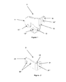
- FIG 1 a perspective view of the upper connection part (1) of the door mounting hinge according to an exemplary embodiment.
- Upper connection part (1) comprises four sections as an upper part top (11) and two side surfaces (13, 14) and a spring nail slot (12).
- One of the side surfaces (14) is used for fixing onto the lateral surface of the oven (not illustrated in figures). This fixing is performed by means of a connection part (not illustrated in figures) passing through the connection space (14") of the side surface (14).
- In the upper connection part (1) is another side surface (13), located perpendicularly to the side surface (14).
- This side surface (13) is fixed to the lower surface (not shown in figures) of the oven.
- This fixing operation is carried out by means of a connection part (not shown) passing through the connection space (13") of the side surface (13).
- FIG 2 a perspective view of the lower connection part (2) of an exemplary embodiment of the door mounting hinge is shown.
- Said lower connection part (2) basically consists of two sections, which are side surface (21) and upper surface (22).
- Lower connection part (2) is joined with the upper connection part (1) by means of a connection rod (4).
- the upper surface (22) is fixed to the door (not shown in figures) by means of connection spaces (22") of the upper surface (22).
- Said connection spaces (22") comprise two holes, and are clearly and safely fixed to the door, thus easing the rigid movement of the door during opening and closing movements.
- FIG 3 a perspective view of a spring (3) in the exemplary embodiment of the door mounting hinge is shown.
- Said cylindrical spring (3) consists of three sections, which are spring nail (31), spring coil (32) and spring end (33).
- Spring nail (31) is seated into a spring nail slot (12) which is in a dimension suitable to receive the same.
- the respective hinges to be located may be situated at any spot on the lateral surfaces of the door (not shown in figures), besides; they may be located on the right and left walls reciprocally and in parallel to each other as well. Therefore, unwanted situations such as imbalance and rolling are avoided during the opening and closing of the door.
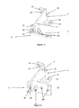
- FIG 4 an exemplary perspective view of a mounted door hinge where an upper connection part (1) and lower connection part (2) are mounted with the connection rod (4) and spring (3) is shown.
- the top connection space (11") of the top of the upper part (11) on the upper part (1) is joined by means of the connection rod (4), in a way to be located inside the connection space (21") of the side surface (21).
- Spring coil (32) is fixed with the connection rod (4).
- Said spring coil (32) is located between the spaces (11", 21") and connection rod (4) passes through this spring coil (32).
- the free spring end (33) is situated in such a way that it corresponds to the corner (23) where the side surface (21) of the lower connection part crosses the upper surface (22) of the lower connection part (2).
- FIG 5 the open position of the said mounted hinge is shown while Figure 6 illustrates an exemplary closed position of the hinge.
- the lower connection part (2) changes from its vertical position into a declined position ( Figure 5 ).
- the spring located horizontally between the upper connection (1) and lower connection parts (2) that are joined together with the connection rod (4), stretches.
- the mentioned door is opened in such a way that it holds a position parallel to the horizontal axis when it is completely opened downwards.
- the opening and closing angle of the door may vary according to the tension of the spring (3).
- the resistance of the said spring (3) may be modified by alteration in the thickness of the spring and the size of the coil. And thanks to the same option, different kinds of doors with different weights may be used.
- said doors are known to have different weights due to various factors, their functions being the first. Therefore, springs which have different levels of resistance suitable for holding various weights should be used depending on the necessity in its field of use.
- the angle at which the said door opens and closes itself can be adjusted through some adjustments in the thickness and coil size of the spring (3) to be used. Therefore, under any occasion, opening and closing of the doors are performed at an optimal level without any complication.
Landscapes
- Engineering & Computer Science (AREA)
- Mechanical Engineering (AREA)
- Closing And Opening Devices For Wings, And Checks For Wings (AREA)
- Furnace Housings, Linings, Walls, And Ceilings (AREA)
Abstract
Description
- This invention is related to a mounting hinge for appliance doors, which can be opened and closed at a desired angle as a result of the type of the lock used and which can hold doors of different weights.
- For white appliances and such, various kinds of doors and flaps of different weights are widely used. The doors of these household appliances, especially the doors of the ovens, are frequently opened and closed during the day. For this reason, the hinge mechanisms of the doors are exposed to load and naturally to the wearing. Consequently, considering the weights of various appliance doors, it is of highest importance to use a door hinge with a mechanism resistance of which is pre-adjusted.
- The problem often faced in said hinge mechanisms is the spaces that emerge in the movable parts of the mechanism over time, caused by over-work and loosening. Because of these spaces, the oven door cannot be closed properly and this causes undesirable leakages of water and heat during the operation of those white appliances, especially of the ovens. Therefore, it is really important that said appliance doors have some features which render their use as practical and functional as possible.
- Owing to the above mentioned reasons, many enhancement methods are put forward in the state-of-the-art, for the hinge mechanisms on the doors of white appliances, ovens in particular. Doors with pressure openings, sliding doors and doors having different features due to a spring use are the some examples of the methods faced in the state of the art. The patent application
US 2005242593 can be regarded as an example of doors with pressure openings, used especially in household goods. The method described in the mentioned patent application is a door opened by applying a manual pressure on the door towards the inner part of the appliance. At least one of the hinges used on that door comprises a spring that takes part while the said appliance door is moved from the open position into the closed position. However, as the mentioned hinge depends on push - pull mechanism, it easily loses its effectiveness over time due to frequent daily usage. Moreover, it is also known to be impractical in terms of use, as it includes a one side door and as it is opened sideways. - The international patent application with the publication number
WO 2009033960 of the state of the art is related to an oven door hinge. In the mentioned application is described a mechanism which operates such that the oven door hinge, when it is opened downwards, stays in a position parallel to the horizontal axis. However, the hinges used in this application cause deficiencies in use, owing to the fact that they are deformed over time as they are not fixed both on the lower and on the upper surface. - In the published patent application no
CA2631198 , a hinge for wings or doors is described. In the mentioned patent application, the hinge comprises a first box-shaped body and a second box-shaped body, and a connecting element between the first and second bodies, and also a damper cylinder. The said damper cylinder is located on the first body, and during the closing movement, it affects the second body and damps the first body's action forward. However, as there are lots of elements on the hinges in the mentioned patent application, those hinges are not practical in the mounting step and also for the high probability of mechanical problems. - The door hinge, subject matter of the present invention, is related to an embodiment that enables the doors and wings of white goods, especially of ovens, to close themselves when lifted to a certain distance after being opened at a certain horizontal angle. The said door hinge, which can be used in white goods and ovens in particular, comprises upper and lower connection parts, connection rod and springs that ease the opening and closing.
- The upper connection part of the upper connection hinge comprises side surfaces required for fixing onto the side and lower surfaces of the oven or of the respective white good, on the right and left walls reciprocally and in parallel to each other. The fixing is carried out by using a connection part. Upper connection part is fixed onto the side connection part by means of a connection rod. The spring nail in the mentioned hinge is seated in the spring slot and the spring coil may be positioned horizontally between the upper part top space and upper surface space. This spring coil is also fixed by means of connection rod to prevent such possible problems as sliding and slipping from the slot. Therefore, the used spring and the said hinge provide rigid movement of door when it is opened.
- Furthermore, in the present invention, with some modifications on the thickness and coiling size of the spring, the said hinge may easily be applied to different kinds of doors with different weights. Along with these, during the closing operation, it is enough to lift the door to a certain distance. The spring mentioned above provides the said hinges with a locking feature which enables the doors to close themselves after lifted at a certain angle.
- The aim of the present invention is to provide a mechanism which will enable the appliance doors to be opened and closed at a desired opening degree, with its own weight.
- Another aim of this invention is to develop a mechanism applicable to appliance doors of different size and different weight.
- Another aim of this invention is to enable quick and practical mounting of the mounting hinge.
- An example of the embodiment of the door mounting hinge in the present invention is illustrated in the annexed figures, of which:
-
Figure 1 is a perspective view of the upper connection part of an exemplary embodiment of the door mounting hinge -
Figure 2 is a perspective view of the lower connection part of an exemplary embodiment of the door mounting hinge -
Figure 3 is a perspective view of a spring of the exemplary embodiment of the door mounting hinge -
Figure 4 is a perspective view of an exemplary mounted hinge according to an embodiment of the present invention -
Figure 5 is a perspective view of the open position of a mounted exemplary embodiment of the door hinge -
Figure 6 is a perspective view of the closed position of a mounted exemplary embodiment of the door hinge. - Each part in these figures are given a reference numeral, list of those is given below as:
- ■ Upper connection part (1)
- ■ Top of upper part (11)
- ■ Top connection space (11"),
- ■ Spring nail slot (12)
- ■ Side surface (13)
- ■ Connection space (13")
- ■ Side surface (14)
- ■ Connection space (14")
- ■ Lower connection part (2)
- ■ Side surface (21)
- ■ Connection space (21")
- ■ Upper surface (22)
- ■ Connection spaces (22")
- ■ Corner (23)
- ■ Spring (3)
- ■ Spring nail (31)
- ■ Spring coil (32)
- ■ Spring end (33)
- ■ Connection rod (4)
- In
Figure 1 , a perspective view of the upper connection part (1) of the door mounting hinge according to an exemplary embodiment. Upper connection part (1) comprises four sections as an upper part top (11) and two side surfaces (13, 14) and a spring nail slot (12). One of the side surfaces (14) is used for fixing onto the lateral surface of the oven (not illustrated in figures). This fixing is performed by means of a connection part (not illustrated in figures) passing through the connection space (14") of the side surface (14). In the upper connection part (1) is another side surface (13), located perpendicularly to the side surface (14). This side surface (13) is fixed to the lower surface (not shown in figures) of the oven. This fixing operation is carried out by means of a connection part (not shown) passing through the connection space (13") of the side surface (13). - In
Figure 2 , a perspective view of the lower connection part (2) of an exemplary embodiment of the door mounting hinge is shown. Said lower connection part (2) basically consists of two sections, which are side surface (21) and upper surface (22). Lower connection part (2) is joined with the upper connection part (1) by means of a connection rod (4). The upper surface (22) is fixed to the door (not shown in figures) by means of connection spaces (22") of the upper surface (22). Said connection spaces (22") comprise two holes, and are clearly and safely fixed to the door, thus easing the rigid movement of the door during opening and closing movements. - In
figure 3 , a perspective view of a spring (3) in the exemplary embodiment of the door mounting hinge is shown. Said cylindrical spring (3) consists of three sections, which are spring nail (31), spring coil (32) and spring end (33). Spring nail (31) is seated into a spring nail slot (12) which is in a dimension suitable to receive the same. The respective hinges to be located may be situated at any spot on the lateral surfaces of the door (not shown in figures), besides; they may be located on the right and left walls reciprocally and in parallel to each other as well. Therefore, unwanted situations such as imbalance and rolling are avoided during the opening and closing of the door. - In
Figure 4 , an exemplary perspective view of a mounted door hinge where an upper connection part (1) and lower connection part (2) are mounted with the connection rod (4) and spring (3) is shown. The top connection space (11") of the top of the upper part (11) on the upper part (1) is joined by means of the connection rod (4), in a way to be located inside the connection space (21") of the side surface (21). Spring coil (32) is fixed with the connection rod (4). Said spring coil (32) is located between the spaces (11", 21") and connection rod (4) passes through this spring coil (32). The free spring end (33) is situated in such a way that it corresponds to the corner (23) where the side surface (21) of the lower connection part crosses the upper surface (22) of the lower connection part (2). - In
Figure 5 , the open position of the said mounted hinge is shown whileFigure 6 illustrates an exemplary closed position of the hinge. While opening the door, the lower connection part (2) changes from its vertical position into a declined position (Figure 5 ). In the meantime, while the door passes from closed position to the open position, the spring, located horizontally between the upper connection (1) and lower connection parts (2) that are joined together with the connection rod (4), stretches. The mentioned door is opened in such a way that it holds a position parallel to the horizontal axis when it is completely opened downwards. Also, the opening and closing angle of the door may vary according to the tension of the spring (3). The resistance of the said spring (3) may be modified by alteration in the thickness of the spring and the size of the coil. And thanks to the same option, different kinds of doors with different weights may be used. - When the door is to be closed, it is enough to lift the door up to a certain point, which depends on the resistance of the spring (3). While the said door is closed (
Figure 6 ), lower connection part (2) starts to turn back to its original vertical position. In the meantime, although the stretched spring (3) tries to sustain its resistance up to a certain point, its resistance starts to decrease gradually. After that, as the spring (3) is naturally likely to go back to its free position, after a certain distance, it is possible to close the door without any need to apply any further pressure. - Moreover, said doors are known to have different weights due to various factors, their functions being the first. Therefore, springs which have different levels of resistance suitable for holding various weights should be used depending on the necessity in its field of use. The angle at which the said door opens and closes itself can be adjusted through some adjustments in the thickness and coil size of the spring (3) to be used. Therefore, under any occasion, opening and closing of the doors are performed at an optimal level without any complication.
Claims (13)
- A door mounting hinge, comprising a connection rod used for joining the connection parts, spring and other related parts, characterized in that;
it comprises side surfaces (13, 14) on the upper connection part (1) in order to fix on the lower and lateral surface of the oven, connection spaces (13", 14") that are used in the process of joining the said surfaces to the oven surfaces, a connection rod (4) joining the lower connection part (2) and upper connection part (1), and a spring (3) situated horizontally on the surface between the upper (1) and lower (1) connection parts, comprising a spring nail (31) seated into a spring nail slot (12) and a spring coil (32) located in the center of spaces (11", 21 "). - A mounting hinge according to Claim 1, characterized in that; on the upper connection part (1), it comprises the said top of upper part (11) and two separate side surfaces (13, 14) and a spring nail slot (12).
- A mounting hinge according to Claims 1 and 2, characterized in that; in the upper connection part (1), it comprises side surfaces (13, 14) located perpendicularly to each other.
- A mounting hinge according to Claim 1, characterized in that; it comprises a connection space (14") on the side surface (14), used in the fixing onto the lateral surface of the oven, and located on the upper connection part (1).
- A mounting hinge according to Claim 1, characterized in that; it comprises a connection space (13") on the side surface (13), used in the operation of fixing onto the lower surface of the oven, and located on the upper connection part (1).
- A mounting hinge according to Claim 1, characterized in that; the lower connection part (2) comprises a side surface (21), upper surface (22) and a corner (23).
- A mounting hinge according to Claim 1, characterized in that; it comprises connection spaces (22") on the upper surface (22) used in the operation of fixing onto the door, and located on the lower connection part (2).
- A mounting hinge according to Claims 1 and 7, characterized in that; the connection spaces (22") used on the upper surface (22) comprises two holes.
- A mounting hinge according to Claim 1, characterized in that; the spring comprises the said spring nail (31), the spring coil (32) and the spring end (33).
- A mounting hinge according to Claim 1, characterized in that; the said door comprises a spring (3), whose thickness and size of coil may be adjusted so as to arrange the angles at which the door opens and closes by itself.
- A mounting hinge according to Claim 1, characterized in that; it comprises a spring end (3) located in such a way to correspond to the corner (23) in a region where the upper surface (22) and the side surface (21) of the lower connection part (2) cross.
- A mounting hinge according to Claim 1, characterized in that; it comprises a connection rod (4) which joins the upper connection part (1) and the lower connection part (2) leaving the spring coil (32) between them, by passing through the top connection space (11 ") of the top of the upper part (11) and also through the inner side of the connection space (21") of the side surface (21).
- A mounting hinge according to Claim 1, characterized in that; the connection space (21") of the side surface (21) on the lower connection part (2) has a space enough for the connection rod (4) to pass through.
Applications Claiming Priority (1)
| Application Number | Priority Date | Filing Date | Title |
|---|---|---|---|
| TR2009/03812A TR200903812A1 (en) | 2009-05-15 | 2009-05-15 | Drawer mounting hinge |
Publications (2)
| Publication Number | Publication Date |
|---|---|
| EP2251512A2 true EP2251512A2 (en) | 2010-11-17 |
| EP2251512A3 EP2251512A3 (en) | 2012-01-04 |
Family
ID=42635256
Family Applications (1)
| Application Number | Title | Priority Date | Filing Date |
|---|---|---|---|
| EP10159263A Withdrawn EP2251512A3 (en) | 2009-05-15 | 2010-04-07 | Door mounting hinge |
Country Status (2)
| Country | Link |
|---|---|
| EP (1) | EP2251512A3 (en) |
| TR (1) | TR200903812A1 (en) |
Citations (3)
| Publication number | Priority date | Publication date | Assignee | Title |
|---|---|---|---|---|
| US20050242593A1 (en) | 2004-04-30 | 2005-11-03 | Agostino Ferrari S.P.A. | Door with a pressure opening |
| CA2631198A1 (en) | 2007-05-23 | 2008-11-23 | Nuova Star S.P.A. | Hinge for wings or doors |
| WO2009033960A1 (en) | 2007-09-07 | 2009-03-19 | Hettich-Oni Gmbh & Co. Kg | Door hinge for a household appliance |
Family Cites Families (2)
| Publication number | Priority date | Publication date | Assignee | Title |
|---|---|---|---|---|
| US1546246A (en) * | 1924-12-18 | 1925-07-14 | American Stove Co | Hinge |
| JP4837533B2 (en) * | 2006-11-29 | 2011-12-14 | 株式会社パイオラックス | Free stop hinge |
-
2009
- 2009-05-15 TR TR2009/03812A patent/TR200903812A1/en unknown
-
2010
- 2010-04-07 EP EP10159263A patent/EP2251512A3/en not_active Withdrawn
Patent Citations (3)
| Publication number | Priority date | Publication date | Assignee | Title |
|---|---|---|---|---|
| US20050242593A1 (en) | 2004-04-30 | 2005-11-03 | Agostino Ferrari S.P.A. | Door with a pressure opening |
| CA2631198A1 (en) | 2007-05-23 | 2008-11-23 | Nuova Star S.P.A. | Hinge for wings or doors |
| WO2009033960A1 (en) | 2007-09-07 | 2009-03-19 | Hettich-Oni Gmbh & Co. Kg | Door hinge for a household appliance |
Also Published As
| Publication number | Publication date |
|---|---|
| TR200903812A1 (en) | 2010-12-21 |
| EP2251512A3 (en) | 2012-01-04 |
Similar Documents
| Publication | Publication Date | Title |
|---|---|---|
| EP3095940B1 (en) | A hinge mechanism | |
| US8533914B2 (en) | Hinge for wings or doors | |
| US8806719B2 (en) | Door hinge for a household appliance | |
| EP2448856B1 (en) | Method and arrangement for opening and closing a suspended ceiling or corresponding of an elevator car and also a locking device | |
| US20130239364A1 (en) | Appliance hinge counterbalance assembly | |
| US6789293B2 (en) | Dampened hinge system for appliance door | |
| WO2020212086A1 (en) | Hinge for the opening and closing of hinged doors of furniture | |
| EP2295692A1 (en) | Door or wing for electrical household appliances | |
| CN108425584B (en) | Furniture hinges that can be easily installed | |
| US9359801B2 (en) | Damper for furniture | |
| US11624223B2 (en) | Side-accessible adjustable receiver for appliance hinge | |
| EP1431671B1 (en) | A door hinge | |
| US2320752A (en) | Deck lid hinge | |
| CA2915048A1 (en) | Kitchen oven | |
| US8056183B2 (en) | Multiple position ball stud for closure strut | |
| US2823662A (en) | Oven door hinge construction | |
| EP2251512A2 (en) | Door mounting hinge | |
| US6637319B1 (en) | Adjustable hinge for oven appliance | |
| US8132294B2 (en) | Snap hinge for furniture | |
| US5433041A (en) | Preassembled operating panel for vehicle doors | |
| EP3387327B1 (en) | Household appliance | |
| RU2531731C2 (en) | Set of fittings for two wings of sliding door | |
| US2904853A (en) | Cabinet structure | |
| WO2008024469A2 (en) | Hinge with adjustable maximum opening angle | |
| JP2006183278A (en) | Door tilt correction tool |
Legal Events
| Date | Code | Title | Description |
|---|---|---|---|
| PUAI | Public reference made under article 153(3) epc to a published international application that has entered the european phase |
Free format text: ORIGINAL CODE: 0009012 |
|
| AK | Designated contracting states |
Kind code of ref document: A2 Designated state(s): AT BE BG CH CY CZ DE DK EE ES FI FR GB GR HR HU IE IS IT LI LT LU LV MC MK MT NL NO PL PT RO SE SI SK SM TR |
|
| AX | Request for extension of the european patent |
Extension state: AL BA ME RS |
|
| PUAL | Search report despatched |
Free format text: ORIGINAL CODE: 0009013 |
|
| AK | Designated contracting states |
Kind code of ref document: A3 Designated state(s): AT BE BG CH CY CZ DE DK EE ES FI FR GB GR HR HU IE IS IT LI LT LU LV MC MK MT NL NO PL PT RO SE SI SK SM TR |
|
| AX | Request for extension of the european patent |
Extension state: AL BA ME RS |
|
| RIC1 | Information provided on ipc code assigned before grant |
Ipc: F24C 15/02 20060101ALI20111125BHEP Ipc: E05D 5/06 20060101ALI20111125BHEP Ipc: E05F 1/12 20060101AFI20111125BHEP |
|
| STAA | Information on the status of an ep patent application or granted ep patent |
Free format text: STATUS: THE APPLICATION IS DEEMED TO BE WITHDRAWN |
|
| 18D | Application deemed to be withdrawn |
Effective date: 20120705 |