EP2251155A1 - Folding sawhorse - Google Patents
Folding sawhorse Download PDFInfo
- Publication number
- EP2251155A1 EP2251155A1 EP10162878A EP10162878A EP2251155A1 EP 2251155 A1 EP2251155 A1 EP 2251155A1 EP 10162878 A EP10162878 A EP 10162878A EP 10162878 A EP10162878 A EP 10162878A EP 2251155 A1 EP2251155 A1 EP 2251155A1
- Authority
- EP
- European Patent Office
- Prior art keywords
- legs
- folding
- folding sawhorse
- plastic body
- pair
- Prior art date
- Legal status (The legal status is an assumption and is not a legal conclusion. Google has not performed a legal analysis and makes no representation as to the accuracy of the status listed.)
- Granted
Links
Images











Classifications
-
- B—PERFORMING OPERATIONS; TRANSPORTING
- B25—HAND TOOLS; PORTABLE POWER-DRIVEN TOOLS; MANIPULATORS
- B25H—WORKSHOP EQUIPMENT, e.g. FOR MARKING-OUT WORK; STORAGE MEANS FOR WORKSHOPS
- B25H1/00—Work benches; Portable stands or supports for positioning portable tools or work to be operated on thereby
- B25H1/06—Work benches; Portable stands or supports for positioning portable tools or work to be operated on thereby of trestle type
-
- B—PERFORMING OPERATIONS; TRANSPORTING
- B25—HAND TOOLS; PORTABLE POWER-DRIVEN TOOLS; MANIPULATORS
- B25H—WORKSHOP EQUIPMENT, e.g. FOR MARKING-OUT WORK; STORAGE MEANS FOR WORKSHOPS
- B25H1/00—Work benches; Portable stands or supports for positioning portable tools or work to be operated on thereby
- B25H1/02—Work benches; Portable stands or supports for positioning portable tools or work to be operated on thereby of table type
- B25H1/04—Work benches; Portable stands or supports for positioning portable tools or work to be operated on thereby of table type portable
-
- E—FIXED CONSTRUCTIONS
- E04—BUILDING
- E04G—SCAFFOLDING; FORMS; SHUTTERING; BUILDING IMPLEMENTS OR AIDS, OR THEIR USE; HANDLING BUILDING MATERIALS ON THE SITE; REPAIRING, BREAKING-UP OR OTHER WORK ON EXISTING BUILDINGS
- E04G1/00—Scaffolds primarily resting on the ground
- E04G1/34—Scaffold constructions able to be folded in prismatic or flat parts or able to be turned down
Definitions
- the present invention relates to a folding sawhorse.
- Conventional sawhorses commonly are comprised of a body and legs that support the body.
- the body is used to support workpieces that are to be cut or otherwise worked on.
- a folding sawhorse comprises an elongate plastic body having a top wall with an upper work surface, and a plurality of side walls, the walls defining a storage compartment.
- the folding sawhorse further comprises a plurality of metal legs that are pivotally disposed relative to the plastic body, the legs being movable between a deployed position wherein the legs are capable of supporting the plastic body in a condition for use, and a storage position in which the legs are folded so as to be substantially disposed in the storage compartment, wherein the metal legs forcibly engage with adjacent plastic surfaces of the plastic body when the legs are in the deployed position.
- the folding sawhorse comprises an elongate body having a top wall with an upper work surface, and a plurality of side walls, the walls defining a storage compartment.
- the folding sawhorse further comprises a plurality of legs, including a first leg pair pivotally mounted towards a first side of the body, and a second leg pair pivotally mounted towards a second side of the body.
- the folding sawhorse further comprises the legs being movable between a deployed position wherein the legs are capable of supporting the plastic body in a condition for use, and a storage position in which the legs are folded so as to be substantially disposed in the storage compartment.
- the folding sawhorse further comprises each leg pair comprising a first pivot axis allowing the pair of legs to be pivoted together outwardly from the storage compartment to an extended position, and a second pivot axis along the pair of legs to be pivotally separated away from one another to the deployed position.
- the first pivot axis and the second pivot axis are provided by a pivot structure.
- the pivot structure is formed from a single structure defining two axes.
- the pivot structure comprises a rod portion and a recess portion.
- the rod portion of the pivot structure is inserted through a through-hole formed in the pair of legs, providing the second pivot axis.
- an inner rod is molded into the inner side of the top wall.
- the recess portion of the pivot structure is pivotally attached to an inner rod providing the first pivot axis.
- the first and second pair of legs pivot relative to the second pivot axis inside the storage compartment, allowing for angled storage positions for first and second pair of legs.
- the folding sawhorse comprises an elongate, one-piece integrally molded plastic body, the one-piece integrally molded plastic body being molded to include each of (a) a top wall defining a work surface, (b) side walls, and (c) a handle portion recessed in the top wall so as not to project above the work surface.
- the folding sawhorse further comprises a plurality of legs that are connected with the body and capable of supporting the body in a condition of use.
- the handle portion is located at a position substantially centered between the side walls.
- the top surface of the handle portion lies in the same plane as the surface as the top wall.
- the top wall serves as the major work surface.
- the top surface of the handle portion can function as part of the work surface.
- the folding sawhorse comprises an elongate body having a top wall with an upper work surface, and a plurality of side walls, the walls defining a storage compartment.
- the folding sawhorse further comprises a plurality of legs that are pivotally disposed relative to the body, the legs being movable between a deployed position wherein the legs are capable of supporting the plastic body in a condition of use, and a storage position in which the legs are folded so as to be substantially disposed in the storage compartment.
- the folding sawhorse further comprises a latch member pivotally connected with one of the side walls and latchable to an opposite of the side walls to lock the legs in the storage compartment.
- the latch member comprises an aperture at one end and an abutment integrally molded with the latch member at the other end.
- the abutment is perpendicular to the length of the latch member.
- the latch member is pivotally connected to one side wall by a fastener.
- one side wall further comprises an integrally molded rib.
- a hole is formed in the rib.
- the hole is configured to receive the abutment.
- the abutment of the latch member is inserted into the hole formed in the rib integrally molded into one side wall.
- FIGS 1 and 2 show a folding sawhorse 1 in accordance with an embodiment of the present invention in a deployed position.
- the folding sawhorse 1 includes an elongate plastic body 2 having a top wall 3 with an upper work surface 4, and a plurality of side walls 5a (shown in Figures 5, 6 , and 7 ), 5b, 6a (shown in Figures 5, 6 , and 7 ), and 6b, the walls defining a storage compartment 7 (as shown in Figures 5, 6 , and 7 ).
- the folding sawhorse 1 further includes a plurality of metal legs 9a, 9b, 9c, and 9d that are pivotally disposed relative to the plastic body 2.
- the legs 9a, 9b, 9c, and 9d are movable between a deployed position wherein the legs 9a, 9b, 9c, and 9d are capable of supporting the plastic body 2 in a condition for use, and a storage position (as shown in Figure 7 ) in which the legs 9a, 9b, 9c, and 9d are folded so as to be substantially disposed in the storage compartment 7.
- the metal legs can be made of any suitable metal such as steel or aluminum, for example.
- the top wall 3 is molded to include an integral plastic handle 8 recessed in the top wall 3 so as not to project above the work surface 4.
- the handle is integrally molded with the top wall 3 and side walls 5a, 5b, 6a, and 6b so that these are all a one-piece unitary molded structure.
- the integral plastic handle 8 is molded into the top wall 3 of the elongate plastic body 2 along upper work surface 4 at a position that is substantially centered between the side walls 6a and 6b and between side walls 5a and 5b.
- the integral plastic handle 8 allows folding sawhorse 1 to be easily carried by hand.
- a top surface of the handle 8 lies in the same plane as the top surface of the top wall 3, which serves as the major work surface.
- the top surface of handle 8 can function as part of the work surface.
- the top wall 3 of the elongate plastic body 2 has folding elements 10a and 10b disposed in recess 11a, and 10c and 10d disposed in recess 11 b.
- the folding elements are pivotally disposed relative to the top wall 3.
- the folding elements 10a, 10b, 10c, and 10d can be pivoted between a storage position in which the folding elements 10a, 10b, 10c, and 10d are folded so as to be substantially disposed within recesses 11 a and 11b (as shown in Figure 1 ), and an upright position (as shown in Figure 2 ).
- folding elements 10a, 10b, 10c, and 10d are of essentially identical construction.
- folding elements 10a, 10b, 10c, and 10d are essentially identical, only folding element 10a will be discussed in detail, but the discussion applies equally to folding elements 10b, 10c, and 10d.
- the folding element 10a has a through-hole (not shown) that transverses the length of the folding element along the lower end of folding element 10a.
- folding element apertures are molded in the top wall 3 within the recess 11 a.
- a metal rod (not shown) is then inserted into folding element aperture, through through-hole, and into another folding element aperture. This configuration allows folding element 10a to be pivotally disposed relative to the top wall 3.
- legs 9a and 9b form a first leg pair that is pivotally disposed relative to each other, while legs 9c and 9d form a second leg pair pivotally disposed relative to each other.
- the first leg pair 9a and 9b is pivotally mounted towards a first side 26 of the plastic body 2.
- the first side 26 of the plastic body 2 is the side of the plastic body between the center of the plastic body and the outer surface by side wall 6b.
- the second leg pair 9a and 9b is pivotally mounted towards a second side 27 of the plastic body 2.
- the second side 27 of the plastic body 2 is the side of the plastic body between the center of the plastic body and the outer surface by side wall 6a. Because leg pair 9a and 9b and leg pair 9c and 9d are essentially identical, any discussion of leg pair 9a and 9b applies equally to leg pair 9c and 9d.
- the leg 9a has a U-shaped cross section formed by two side rails 16a and 16b and a center rail 17a defining a channel 18a (obstructed from view by leg 9a) along the length of leg 9a.
- leg 9b includes two side rails 16a' and 16b' and a center rail 17b (partially obstructed from view by side rail 16b') defining a channel 18b along the length of leg 9b.
- the center rails 17a and 17b include openings 45a, 45a' and 45b (shown in Figure 10 ), 45b' (shown in Figure 10 ), respectively.
- the leg 9a and 9b each have two ends, top ends 19a (obstructed from view by plastic body 2), 19b (obstructed from view by plastic body 2), respectively, and bottom ends 20a, 20b, respectively. Furthermore, shoes 15a, 15b partially cover legs 9a, 9b, respectively, at the bottom ends 20a, 20b, respectively.
- the shoes 15a, 15b provide a slip resistant surface (e.g., made of plastic, rubber or elastomer) for the legs 9a, 9b when legs 9a, 9b are in a deployed position supporting the plastic body 2 in a condition for use.
- legs 9c, 9d are substantially the same as legs 9a, 9b the foregoing description applies equally to those legs as well.
- the shoes 15a, 15b may also protect the underlying floor surface.
- an support rail 13a is disposed between leg pair 9a and 9b to further stabilize leg pair 9a and 9b in the deployed position.
- Support rails 13a and 13b are of essentially identical construction. Because support rail 13a and 13b are essentially identical, only support rail 13a will be discussed in detail, but the discussion applies equally to support rail 13b.
- the support rail 13a has two portions 14a and 14b. Each portion 14a and 14b is substantially one half of support rail 13a.
- the portions 14a and 14b are pivotally disposed relative to each other at ends 85a, 85b, respectively, and pivotally disposed relative to legs 9a and 9b via hinges disposed at openings 45a, 45a' and 45b, 45b' in the legs 9a and 9b (shown in Figure10 ), respectively.
- the leg pair 9a and 9b is in a deployed position, capable of supporting the plastic body 2 in a condition for use.
- the support rail 13a is made of plastic.
- the use of plastic is not intended to be limiting, and the support rail 13a may be made of any other suitable material or combination thereof as is well known in the art.
- FIG 3 shows an embodiment wherein legs 9a and 9b are partially collapsed inwardly toward each other.
- the support rail 13a is folded when portions 14a and 14b are collapsed toward each other.
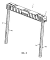
- Figure 4 shows an embodiment wherein leg pair 9a and 9b and leg pair 9c and 9d are fully collapsed together. Leg pair 9a and 9b and leg pair 9c and 9d are in an extended position.
- the support rail 13a is folded so that the two portions 14a (shown in Figure 3 ) and 14b (shown in Figure 3 ) are collapsed together.
- the support rail 13a is entirely disposed within channels 18a, 18b.
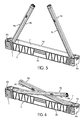
- FIG 5 shows an embodiment wherein the leg pair 9a, 9b and the leg pair 9c, 9d are fully collapsed together. Each leg pair 9a and 9b, and 9c and 9d is partially folded inwardly from the extended position toward the storage compartment 7.
- FIG 6 shows an embodiment wherein the leg pair 9a and 9b and the leg pair 9c and 9d are fully collapsed together. Each leg pair 9a and 9b, and 9c and 9d is further folded toward the storage compartment 7.
- leg pair 9a, 9b and leg pair 9c, 9d are in a storage position in which the leg pair 9a, 9b and leg pair 9c, 9d are folded so as to be substantially disposed in the storage compartment 7.
- a pivot structure 22 which is used to pivotally mount a pair of legs to the body as will be described, comprises a recess portion 23 and a rod portion 24.
- the recess portion 23 forms a first pivot axis X.
- the rod portion 24 forms a second pivot axis Y.
- the pivot structure 22 is made of plastic.
- Figures 9 and 10 show an embodiment wherein the rod portion 24 of the pivot structure 22 is inserted through through-holes 25 (obstructed from view by pivot structure 22) formed in both side rails 16a, 16b and 16a', 16b' of the legs 9a and 9b, respectively. Therefore, the rod portion 24 of the pivot structure 22 forms the second pivot axis Y allowing the pair of legs 9a and 9b to be pivotally separated away from one another to and from the deployed position.
- the leg pair 9a and 9b is pivoted relative to the first pivot axis X from the storage compartment 7 to a partially extended position.
- the rod portion 24 of the pivot structure 22 is inserted through through-holes 25 (partially obstructed from view by rod portion 24) formed in side rails 16a, 16b and 16a', 16b' of legs 9a, 9b, respectively.
- the recess portion 23 of the pivot structure 22 comprises a resilient C-shaped clamp that receives an inner rod 33 (shown in Figure 13 ) molded into the inner side of the top wall 3 of the plastic body 2 so as to be pivotally connected to the inner rod 33.
- the recess portion 23 of the pivot structure 22 is pivotally disposed relative to the top wall 3, forming a first pivot axis X and allows the legs 9a and 9b (shown in Figure 12 ) to be pivoted together into the storage compartment 7.
- the top ends 19a, 19b of legs 9a, 9b, respectively, are within a leg retaining compartment 29a.
- the leg retaining compartment 29a is formed by side wall 6b, top wall 3, inner ramps 30a and 30b, and side wall ramps 31 a and 31 b.
- the leg retaining compartment 29a is on the first side 26 of the plastic body 2.
- Another leg retaining compartment 29b (obstructed from view in Figures 1 and 2 by side wall 5b) is on the second side 27 (shown in Figure 1 ) of the plastic body 2.
- Leg retaining compartment 29a and 29b are of essentially identical construction. Because leg retaining compartments 29a and 29b are essentially identical, only leg retaining compartment 29a will be discussed in detail, but the discussion applies equally to leg retaining compartment 29b.
- Inner ramps 30a and 30b are integrally molded with the inner surface of side walls 5a and 5b of the plastic body 2.
- Each inner ramp 30a and 30b is essentially identical, but molded on opposite side walls 5a and 5b, respectively.
- Each inner ramp 30a, 30b has a triangle-like configuration, with one side 67a, 67b, respectively, forming part of the leg retaining compartment 29a, one side 68a, 68b, respectively, formed by side wall 5a, 5b, respectively, and the hypotenuse 69a, 69b, respectively, molded to connect the sides 67a, 67b, respectively, and sides 68a, 68b, respectively.
- inner ramps 30a, 30b may have any other suitable configuration.
- Inner ramps 30a and 30b are spaced apart a distance approximately equal to the width of leg pair 9a, 9b when leg pair 9a, 9b is in a collapsed position. Therefore, inner ramps 30a, 30b form an opening 32 that permits leg pair 9a and 9b to be folded so as to be substantially disposed in the storage compartment 7.
- the inner ramps 30a and 30b also function to guide leg pair 9a, 9b toward one side of storage compartment 7 when leg pair 9a, 9b is collapsed into a storage position.
- the legs 9a, 9b pivotally connected toward the first side 26 of the top body 2 is received toward the bottom side of the compartment 7, while the legs 9c, 9d are received toward the upper side of the compartment 7.
- the leg pairs 9a, 9b and 9c, 9d are disposed at an angle with respect to the longitudinal axis of top body 2.
- the side wall ramps 31 a, 31 b are molded on the inner side of the side walls 5a, 5b, respectively, of plastic body 2. The surface of the side wall ramps 31 a, 31 b is slanted outwardly from the top wall 3.
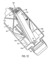
- Figure 12 shows an embodiment wherein the leg pair 9a, 9b is further pivoted relative to the first pivot axis X from the storage compartment 7 to a partially extended position.
- Figure 13 shows an embodiment wherein the leg pair 9a, 9b is pivoted relative to the first pivot axis X from the storage compartment 7 to an extended position.
- the top end 19a (obstructed from view by legs 9a, 9b), 19b (obstructed from view by legs 9a, 9b) of legs 9a, 9b is connected within the leg retaining compartment 29a.
- legs 9a and 9b are at least partially nested within one another.
- the side rail 16b is at least partially within channel 18b.
- Side rail 16a is outside channel 18b.
- Side rail 16b' is at least partially within channel 18a.
- Side rail 16a' is outside channel 18a.
- Side rail 16a overlaps with side rail 16b'.
- Side rail 16b overlaps with side rail 16a'. This partially nested position enables legs 9a, 9b to be compactly arranged when folded into the storage compartment 7.
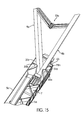
- the leg pair 9a, 9b is in an extended position and partially separated away from one another.
- the plastic material forming inner ramps 30a (shown in Figure 15 ), 30b (shown in Figure 15 ) and side wall 6b (or inner wall structure spaced from side wall 6b) forcibly or frictionally engage leg pair 9a, 9b, inhibiting the leg pair 9a, 9b from pivoting relative to pivot axis X (shown in Figures 8 and 9 ).
- the leg retaining compartment 29a has a width dimension (when the legs are stored and the plastic material of the inner ramps 30a, 30b are not stressed) that is slightly less than the corresponding width dimension of the legs 9a, 9b. This forcible engagement of the plastic material with the legs facilitates retention of the legs in the deployed position with little or no wiggle or relative movement between the legs 9a, 9b and the plastic body 2.
- leg pair 9a and 9b is in an extended position and the legs 9a and 9b are pivotally separated away from one another to the deployed position.
- the plastic surfaces of inner ramps 30a and 30b and side wall 6b forcibly engage leg pair 9a, 9b, inhibiting or selectively preventing the leg pair 9a, 9b from pivoting relative to pivot axis X (shown in Figures 8 and 9 ) until manually pivoted.
- the side wall ramps 31 a and 31b (obstructed from view by leg 9a) also forcibly engage leg pair 9a, 9b, respectively, preventing the leg pair 9a, 9b from pivoting relative to the pivot axis Y (shown in Figures 8 and 9 ) until manually pivoted when desired.
- the body can be molded such that any shaped plastic structure can be formed to engage the metals legs and forcibly retain them in the deployed configuration.
- the forcible engagement of the metal legs slightly displaces the softer and more flexible material of the plastic, and the resilience of the displaced plastic (of whatever shape that may be engineered) applies a force against the metal legs to retain them in place.
- leg pair 9a and 9b is partially separated away from one another.
- Support rail 13a is folded such that portions 14 and 14b are partially folded together.
- Portions 14a and 14b are made from a resilient flexible plastic material.
- legs 9a and 9b are pivotally separated away from one another in a deployed position.
- Support rail 13a is in a straight position such that portions 14a and 14b are aligned horizontally next to each other.
- each portion 14a and 14b of the support rail 13a has ring portions, 44a and 44b (obstructed from view by ring portions 44a and 44b') for portion 14a, and 44a' (obstructed from view by ring portions 44a, 44b', and 44b) and 44b' (partially obstructed from view by ring portion 44a) for portion 14b, integrally molded on one end.
- Each ring portion 44a, 44b, 44a', 44b' is essentially identical and semi-circular in shape. Therefore, portion 14a has ring portions 44a, 44b integrally molded on one end. Portion 14b has ring portions 44a', 44b' integrally molded on one end.
- Each ring portion 44a, 44b, 44a', and 44b' has a center hole 60a, 60b (obstructed from view by ring portions 44a and 44b'), 60a' (obstructed from view by ring portions 44a, 44b', and 44b), and 60b' (obstructed from view by ring portion 44a), respectively, located at a substantially centered position.
- Ring portions 44a, 44b and 44a', 44b' are molded below the top surfaces 61a and 61 b, respectively, of portions 14a and 14b, respectively.
- portions 14a and 14b are pivotally disposed relative to each other.
- portion 14a is aligned with portion 14b such that center hole 60a in portion 14a is aligned with center hole 60b' in portion 14b, and center hole 60b is aligned with center hole 60a'.
- a fastener pin 48a is inserted through center holes 60a and 60b'.
- a fastener pin 48b (shown in Figure 13 ) is also inserted through center holes 60b and 60a'. Therefore, portions 14a and 14b are fastened together, and pivotally disposed relative to one another.
- ring receiving surfaces 72a, 72b (obstructed from view by ring portions 44a, 44b'), 72a' (obstructed from view by ring portions 44a, 44b', and 44b) and 72b'(obstructed from view by ring portion 44a) are located at a position adjacent to ring portions 44a, 44b, 44a', and 44b', respectively.
- Ring receiving surfaces 72a, 72b, 72a', and 72b' are essentially identical and have a curved shape configured to receive a portion of ring portions 44a, 44b, 44a' and 44b', respectively.
- First stop surfaces 70a and 70b are flat and are located above ring portions 44a and 44b, respectively, and below top surface 61 a.
- First stop surfaces 70a' (obstructed from view by ring portion 44a, 44b', and 44b) and 70b' (obstructed from view by ring portions 44a) are located above ring portions 44a' and 44b', respectively, and below top surface 61 b.
- Second stop surfaces 71a, 71 b are located above ring receiving surfaces 72a, 72b, respectively, and below top surface 61 b.
- Second stop surfaces 71a' (obstructed from view by ring portions 44a, 44b', and 44b), 71b' (obstructed from view by ring portion 44a) are flat and are located above ring receiving surfaces 72a', 72b', respectively, and below top surface 61 a. Second stop surfaces 71 a, 71 b, 71 a' and 71 b' are essentially identical.
- Second stop surfaces 71 a, 71 b, 71 a' and 71 b' intersect with ring receiving surfaces 72a, 72b, 72a' and 72b', respectively, at vertexes 84a, 84b (obstructed from view by ring portions 44a, 44b'), 84a' (obstructed from view by ring portions 44a, 44b', and 44b) and 84b' (obstructed from view by ring portion 44a), respectively.
- Second stop surfaces 71 a, 71 b, 71 a' and 71 b' contact first stop surfaces 70a, 70b, 70a' and 70b', respectively, when support rail 13a is in a straight position.
- first stop surfaces 70a, 70b, 70a' and 70b' and second stop surfaces 71 a, 71 b, 71a' and 71 b' prevents or inhibits the ring portions 44a, 44b, 44a' and 44b' from pivoting or moving away from the plastic body 2 (as shown in Figure 20 ; plastic body 2 shown in Figure 1 ) unless the force applied to the support rail 13a exceeds a threshold level.
- first stop surfaces 70a, 70b, 70a' and 70b' are displaced from being in contact with second stop surfaces 71 a, 71 b, 71a' and 71 b', respectively, and pass over vertexes 84a, 84b, 84a' and 84b', respectively, into a position below the second stop surfaces 71 a, 71 b, 71a' and 71 b', respectively.
- the threshold level required to pivot or move ring portions 44a, 44b of portion 14a and ring portions 44a', 44b' of portion 14b away from the plastic body 2 is greater than the force required to pivot portions 44a, 44b, 44a', and 44b' toward the plastic body 2 (as shown in Figure 17 ; plastic body 2 shown in Figure 1 ). Therefore, when portions 14a and 14b are pivotally disposed relative to each other, the force required to pivot or move the ring portions 44a, 44b, 44a' and 44b' away from the plastic body is greater than the force required to pivot or move ring portions 44a, 44b, 44a' and 44b' toward the plastic body 2.
- the support rail 13a is folded such that ring portions 44a, 44b of portion 14a and ring portions 44a', 44b' of portion 14b are pivoted or moved away from the plastic body 2.
- the force applied to the support rail 13a must exceed a threshold level.
- the threshold level required to pivot or move ring portions 44a, 44b of portion 14a and ring portions 44a', 44b' of portion 14b away from the plastic body 2 is greater than the force required to pivot or move ring portions 44a, 44b, 44a', and 44b' toward the plastic body 2 (shown in Figure 17 ). This can occur when a user (inadvertently) steps on the support rail 13a.
- each portion 14a and 14b of the support rail 13a has a rod portion 47a and 47b, respectively, integrally molded on the end opposite from ring portions 44a, 44b and 44a', 44b', respectively.
- Ring portions 44a, 44b (partially obstructed from view by portions 44a and 44b') and rod portion 47a are integrally molded with portion 14a so as to form a one-piece unitary molded structure.
- ring portions 44a' (obstructed from view by portions 44a, 44b', and 44b), 44b' (partially obstructed from view by portion 44a) and rod portion 47b are integrally molded with portion 14b so as to form a one-piece unitary molded structure. Because portions 14a, 14b are essentially identical, only portion 14a will be discussed in detail in this paragraph, but the discussion applies equally to portion 14b. Recesses 49a, 49b, and 49c are located between the rod portion 47a and the rest of portion 14a.
- portion 14a is pivotally disposed relative to a rod receiving member 50a.
- Portion 14b is pivotally disposed relative to rod receiving member 50b.
- Rod receiving members 50a and 50b are mounted through the openings 45a (shown in Figure 1 ), 45a' (shown in Figure 1 ) on leg 9a (shown in Figure 1 ) and 45b (shown in Figure 10 ), 45b' (shown in Figure 10 ) on leg 9b (shown in Figure 10 ), respectively, and affixed inside channels 18a (shown in Figure 13 ) and 18b (shown in Figure 13 ), respectively.
- rod receiving members 50a and 50b are essentially identical, only rod receiving member 50a will be discussed in detail, but the discussion applies essentially to the rod receiving member 50b.
- the rod receiving member 50a has curved portions 73a, 73b (partially obstructed from view by rod portion 47a and rod receiving member 50a), and 73c (obstructed from view by rod portion 47a and rod receiving member 50a) integrally molded with the rod receiving member 50a.
- Curved portions 73a, 73b, and 73c are essentially identical, each having a curved shape forming recesses 74a, 74b, and 74c configured to receive rod portion 47a.
- Rod receiving member 50a receives the rod portion 47a into recesses 74a, 74b, and 74c such that curved portions 73a, 73b, and 73c are aligned with recesses 49a, 49b, and 49c, respectively, allowing portion 14a to be pivotally disposed relative to rod receiving member 50a.
- Tabs 81 a and 81a' are latched through openings 45a and 45a' to affix rod receiving member 50a inside channel 18a (shown in Figure 14 ).
- the stop tab 82 forcibly engages the inner surface of the center rail 17a (shown in Figure 14 ) to help affix rod receiving member 50a inside channel 18a.
- leg pair 9a, 9b and leg pair 9c, 9d are frictionally held in place in the storage compartment by ribs 21 a, 21 b, 21 c, 21 d, 21 e, and 21f integrally molded the side walls 5a and 5b.
- Side wall 5b has integral plastic ribs 21 a, 21 b, 21 c molded at equally spaced positions along the inner surface.
- Side wall 5a also has ribs 21 d, 21 e, 21f molded at equally spaced positions along the inner surface.
- leg pair 9a, 9b and leg pair 9c, 9d forcibly engage with the ribs 21 a, 21 b, 21 c, 21 d, 21 e, and 21f, displacing the plastic material slightly so that legs 9a, 9b, 9c, and 9d remain in a storage position.
- Each rib 21 a, 21 b, 21 c, 21 d, and 21 e is essentially identical.
- a latch member 28 is pivotally connected to side wall 5a by a fastener 42 and latchable to the opposite side wall 5b to further prevent the legs from pivoting from a storage position into an extended position.
- the latch member 28 is approximately the same length as distance between the inner surfaces of side walls 5a and 5b.
- the latch member 28 comprises an aperture 39 at one end and an abutment 40 at the other end.
- the abutment 40 is integrally molded with the latch member 28 so as to form a one-piece unitary molded structure.
- the abutment 40 is perpendicular to the length of the latch member 28.
- An ring 38 with an opening 41 is molded with the side wall 5a adjacent to rib 21e for receiving a fastener 42.
- the fastener 42 is then inserted through the aperture 39 and inside the opening 41, pivotally fastening the latch member 28 to the side wall 5a.
- the abutment 40 is inserted into a hole 43 (partially obstructed from view) formed in rib 21 b.
- the latch member 28 is made of plastic.
- plastic is not intended to be limiting, and the latch member 28 may be made of metal or any other suitable material or combination thereof as is well known in the art.
- the folding sawhorse 1 is in a storage position.
- Legs 9a are 9b are partially nested within one another.
- Legs 9c and 9d are also partially nested within one another.
- the leg pair 9a, 9b connected to first side 26 are disposed parallel to the leg pair 9c, 9d connected to the second side 27 of the folding sawhorse 1.
- Leg pair 9a, 9b is pivoted relative to pivot axis Y (shown in Figures 8 and 9 ) toward side wall 5a.
- leg pair 9c, 9d is pivoted relative to pivot axis Y (shown in Figures 8 and 9 ) toward side wall 5b.
- leg pair 9a, 9b toward side wall 5a and leg pair 9c, 9d toward side wall 5b allows for angled storage position for legs 9a, 9b, 9c, and 9d.
- the hypotenuse 69a (shown in Figure 11 ) of inner ramp 30a (shown in Figure 11 ) operates to guide the legs 9a, 9b to have an angled orientation relative to a central longitudinal axis of the body 2 when in the storage position to enable leg pair 9a, 9b connected to first side 26 of the folding sawhorse 1 to be positioned in a side-by-side relationship to leg pair 9c, 9d connected to second side 27 of the folding sawhorse 1 when in the storage position.
- another hypotenuse (not shown) of another inner ramp (not shown) on second side 27 operates to guide the legs 9c, 9d to have an angled orientation relative to a central longitudinal axis of the body 2 when in the storage position to enable leg pair 9c, 9d connected to second side 27 of the folding sawhorse 1 to be positioned in a side-by-side relationship to leg pair 9a, 9b connected to first side 26 of the folding sawhorse 1 when in the storage position.
- the angled orientation of legs 9a, 9b, 9c, and 9d enable both leg pair 9a, 9b and leg pair 9c, 9d to be compactly stored inside the storage compartment 7.
- a connecting latch 12 is connected relative to side wall 6b.
- the connecting latch 12 comprises a latching portion 52, pivoting rod 53 (obstructed from view by latch retaining protrusion 54), and a handle 56.
- the connecting latch 12 enables the folding sawhorse 1 to be latched to another folding sawhorse 1' (shown in Figures 27, 28 , and 29 ).
- a latch retaining protrusion 54 is molded with side wall 6b.
- the latch retaining protrusion 54 further comprises a recess or optionally a protrusion configured to pivotally connect with pivoting rod 53 so that connecting latch 12 is pivotally disposed relative to side wall 6b.
- latch retaining abutments 34a, 34b, 34c, and 34d are molded into the outer surface of the side wall 6b.
- Latch retaining abutments 34a, 34b, 34c, and 34d are essentially identical.
- Each latch retaining abutment has lower surfaces 75a, 75b, 75c and 75d (collectively 75) (shown in Figures 25 and 26 ), respectively, and upper surfaces 76a, 76b, 76c and 76d (collectively 76), respectively.
- the lower surfaces 75 are curved surfaces configured for receiving latching portion 52.
- the upper surfaces 76 are curved surfaces on latch retaining abutments 34 that are a larger distance away from side wall 6b than the distance between lower surfaces 75 and side wall 6b.
- Lower surfaces 75 are concave (curved inwardly), while upper surfaces 76 are convex (curved outwardly).
- the latching portion 52 must first contact upper surfaces 76 when latching portion 52 is forcibly engaged with the latch retaining abutments 34.
- the width dimension between latching portion 52 and pivoting rod 53 is slightly less than the width dimension between pivoting rod 53 and upper surfaces 76.
- latching portion 52 is forcibly engaged with the upper surfaces 76 of leg retaining abutments 34. Because the connecting latch 12 and leg retaining abutments 34 are both made of resilient flexible plastic material, the forcible engagement between the connecting latch 12 and the leg retaining abutments 34 displaces the latching portion 52 and upper surfaces 76, allowing the latching portion 53 to contact lower surfaces 75. The contact between latching portion 52 and lower surfaces 75 frictionally holds connecting latch 12 along side wall 6b (as shown in Figure 19 ).
- Each latch retaining abutment 34a, 34b, 34c, and 34d provides an incremental amount of frictional force for holding connecting latch 12 against side wall 6b.
- the configuration described is a "snap fit" configuration where the latching portion 52 "snap fits” with leg retaining abutments 34. This configuration prevents the connecting latch 12 from swinging freely (shown in Figures 20 and 21 ) when connecting latch 12 is not in use.
- the connecting latch 12 is held along side wall 6b by leg retaining abutments 34.
- side wall 6a has latch receiving protrusion 64 having latch receiving abutments 35a, 35b, 35c, and 35d (collectively referred to as 35) molded into the outer surface of side wall 6a.
- Latch receiving protrusion 64 and latch receiving abutments 35 are essentially identical to latch retaining protrusion 54 (shown in Figures 22 , 23 and 24 ) and latch retaining abutments 34 (shown in Figures 22 , 23 and 24 ), respectively.
- the only difference between latch receiving protrusion 64 and latch retaining protrusion 54 is that latch retaining protrusion 54 carries connecting latch 12.
- latch receiving abutments 35 are essentially identical to latch retaining abutments, latch receiving abutments 35 essentially operate identically to latch retaining abutments 34 to receive a connecting latch 12' (shown in Figures 29 and 30 ) of another folding sawhorse 1' (shown in Figures 29 and 30 ).
- folding sawhorse 1 is placed on top of folding sawhorse 1' such that the storage compartment 7 of folding sawhorse 1 faces the storage compartment 7' of folding sawhorse 1'. Furthermore, the folding sawhorses 1 and 1' are aligned such that connecting latch 12 on folding sawhorse 1 can be latched to latch receiving abutments 35 on folding sawhorse 1'. The connecting latch 12 of folding sawhorse 1 is then latched to the latch receiving abutments 35 of folding sawhorse 1', and vice versa for folding sawhorse 1'. When latched together, the two folding sawhorses 1 and 1' form a twin pack configuration 36 (as shown in Figure 26 ). The twin pack configuration 36 enables both folding sawhorse 1 and 1' to be more easily carried from one place to another.
- a carrying strap 37 is attached to side walls 6a and 6b of the twin pack configuration 36 of folding sawhorses 1 and 1'.
- the carrying strap 37 may be adjustable. A user 46 can then carry the twin pack configuration 36 from one place to another.
Landscapes
- Engineering & Computer Science (AREA)
- Mechanical Engineering (AREA)
- Architecture (AREA)
- Civil Engineering (AREA)
- Structural Engineering (AREA)
- Rigid Containers With Two Or More Constituent Elements (AREA)
- Purses, Travelling Bags, Baskets, Or Suitcases (AREA)
- Pivots And Pivotal Connections (AREA)
Abstract
Description
- The present invention relates to a folding sawhorse.
- Conventional sawhorses commonly are comprised of a body and legs that support the body. The body is used to support workpieces that are to be cut or otherwise worked on. There is a need in the art for an improved sawhorse.
- A folding sawhorse is disclosed. The folding sawhorse comprises an elongate plastic body having a top wall with an upper work surface, and a plurality of side walls, the walls defining a storage compartment. The folding sawhorse further comprises a plurality of metal legs that are pivotally disposed relative to the plastic body, the legs being movable between a deployed position wherein the legs are capable of supporting the plastic body in a condition for use, and a storage position in which the legs are folded so as to be substantially disposed in the storage compartment, wherein the metal legs forcibly engage with adjacent plastic surfaces of the plastic body when the legs are in the deployed position.
- In another aspect, the folding sawhorse comprises an elongate body having a top wall with an upper work surface, and a plurality of side walls, the walls defining a storage compartment. The folding sawhorse further comprises a plurality of legs, including a first leg pair pivotally mounted towards a first side of the body, and a second leg pair pivotally mounted towards a second side of the body. The folding sawhorse further comprises the legs being movable between a deployed position wherein the legs are capable of supporting the plastic body in a condition for use, and a storage position in which the legs are folded so as to be substantially disposed in the storage compartment. The folding sawhorse further comprises each leg pair comprising a first pivot axis allowing the pair of legs to be pivoted together outwardly from the storage compartment to an extended position, and a second pivot axis along the pair of legs to be pivotally separated away from one another to the deployed position. Preferably the first pivot axis and the second pivot axis are provided by a pivot structure. Preferably the pivot structure is formed from a single structure defining two axes. Preferably the pivot structure comprises a rod portion and a recess portion. Preferably the rod portion of the pivot structure is inserted through a through-hole formed in the pair of legs, providing the second pivot axis. Preferably an inner rod is molded into the inner side of the top wall. Preferably the recess portion of the pivot structure is pivotally attached to an inner rod providing the first pivot axis. Preferably the first and second pair of legs pivot relative to the second pivot axis inside the storage compartment, allowing for angled storage positions for first and second pair of legs.
- In another aspect of the invention, the folding sawhorse comprises an elongate, one-piece integrally molded plastic body, the one-piece integrally molded plastic body being molded to include each of (a) a top wall defining a work surface, (b) side walls, and (c) a handle portion recessed in the top wall so as not to project above the work surface. The folding sawhorse further comprises a plurality of legs that are connected with the body and capable of supporting the body in a condition of use. Preferably the handle portion is located at a position substantially centered between the side walls. Preferably the top surface of the handle portion lies in the same plane as the surface as the top wall. Preferably the top wall serves as the major work surface. Preferably the top surface of the handle portion can function as part of the work surface.
- In another aspect, the folding sawhorse comprises an elongate body having a top wall with an upper work surface, and a plurality of side walls, the walls defining a storage compartment. The folding sawhorse further comprises a plurality of legs that are pivotally disposed relative to the body, the legs being movable between a deployed position wherein the legs are capable of supporting the plastic body in a condition of use, and a storage position in which the legs are folded so as to be substantially disposed in the storage compartment. The folding sawhorse further comprises a latch member pivotally connected with one of the side walls and latchable to an opposite of the side walls to lock the legs in the storage compartment. Preferably the latch member comprises an aperture at one end and an abutment integrally molded with the latch member at the other end. Preferably the abutment is perpendicular to the length of the latch member. Preferably the latch member is pivotally connected to one side wall by a fastener. Preferably one side wall further comprises an integrally molded rib. Preferably a hole is formed in the rib. Preferably the hole is configured to receive the abutment. Preferably the abutment of the latch member is inserted into the hole formed in the rib integrally molded into one side wall.
- These and other aspects of the present invention, as well as the methods of operation and functions of the related elements of structure and the combination of parts and economies of manufacture, will become more apparent upon consideration of the following description and the appended claims with reference to the accompanying drawings, all of which form a part of this specification, wherein like reference numerals designate corresponding parts in the various figures. In one embodiment of the invention, the structural components illustrated herein may be considered to be drawn to scale. It is to be expressly understood, however, that the drawings are for the purpose of illustration and description only and are not a limitation of the invention. In addition, it should be appreciated that structural features shown or described in any one embodiment herein can be used in other embodiments as well. As used in the specification and in the claims, the singular form of "a", "an", and "the" include plural referents unless the context clearly dictates otherwise.
-
Figure 1 is a perspective view of a folding sawhorse in accordance with an embodiment of the present invention in a deployed position. -
Figure 2 is a perspective view of the folding sawhorse in a deployed position with the folding elements in an upright position. -
Figure 3 is a perspective view of the folding sawhorse with the legs partially collapsed toward each other. -
Figure 4 is a perspective view of the folding sawhorse with the legs fully collapsed together. -
Figure 5 is a perspective view of the folding sawhorse with the legs collapsed and partially folded inwardly. -
Figure 6 is a perspective view of the folding sawhorse with the legs further folded toward the storage compartment. -
Figure 7 is a perspective view of the folding sawhorse with the legs substantially disposed in the storage compartment. -
Figure 8 is a perspective view of a pivot structure. -
Figure 9 is a partial perspective view of the pivot structure forming a pivot axis for a pair of legs. -
Figure 10 is a perspective view of the pivot structure forming a pivot axis for a pair of legs. -
Figure 11 is a partial perspective view of the leg retaining compartment with a leg pair in a partially extended position. -
Figure 12 is a partial perspective view of the leg retaining compartment with the leg pair in a further partially extended position. -
Figure 13 is a partial perspective view of the leg retaining compartment with the leg pair in an extended position. -
Figure 14 is a partial perspective view of the leg retaining compartment with the leg pair in an extended position and partially separated. -
Figure 15 is a perspective view of the of the leg retaining compartment with the leg pair in an extended position and partially separated. -
Figure 16 is a partial perspective view of the leg retaining compartment with the leg pair in an extended position and pivotally separated to a deployed position. -
Figure 17 is a perspective view of the leg pair in a partially separated position. -
Figure 18 is a perspective view of the leg pair in a pivotally separated position. -
Figure 19 is a partial perspective view of the support rail showing the ring portions. -
Figure 20 is a perspective view of the leg pair with the ring portions of the support rail pivoted away from the plastic body. -
Figure 21 is a perspective view of the support rail, showing both ring portions and rod portions. -
Figure 22 is a perspective view of the support rail and rod receiving members. -
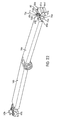
Figure 23 is a perspective view of the folding sawhorse with the legs in a storage position showing the latch member. -
Figure 24 is a partial perspective view of the folding sawhorse with a connecting latch held in a position along the side wall. -
Figure 25 is a partial perspective view of the folding sawhorse with the connecting latch pivoted away from the side wall. -
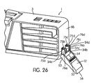
Figure 26 is a partial perspective view of the folding sawhorse with the connecting latch further pivoted away from the side wall. -
Figure 27 is a perspective view of the folding sawhorse showing the connecting latch. -
Figure 28 is a perspective view of the folding sawhorse showing the latch receiving abutments. -
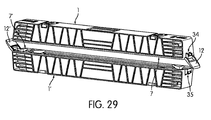
Figure 29 is a perspective view of one folding sawhorse above another folding sawhorse. -
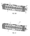
Figure 30 is a perspective view of one folding sawhorse aligned on top of another folding sawhorse. -
Figure 31 is a perspective view of two folding sawhorses latched together, forming a twin pack configuration. -
Figure 32 is a perspective view of a user carrying two sawhorses in a twin pack configuration with a carrying strap. -
Figures 1 and2 show afolding sawhorse 1 in accordance with an embodiment of the present invention in a deployed position. Thefolding sawhorse 1 includes an elongateplastic body 2 having atop wall 3 with anupper work surface 4, and a plurality ofside walls 5a (shown inFigures 5, 6 , and7 ), 5b, 6a (shown inFigures 5, 6 , and7 ), and 6b, the walls defining a storage compartment 7 (as shown inFigures 5, 6 , and7 ). Thefolding sawhorse 1 further includes a plurality ofmetal legs plastic body 2. Thelegs legs plastic body 2 in a condition for use, and a storage position (as shown inFigure 7 ) in which thelegs storage compartment 7. The metal legs can be made of any suitable metal such as steel or aluminum, for example. - In the embodiment shown in
Figures 1 and2 , thetop wall 3 is molded to include an integralplastic handle 8 recessed in thetop wall 3 so as not to project above thework surface 4. The handle is integrally molded with thetop wall 3 andside walls plastic handle 8 is molded into thetop wall 3 of the elongateplastic body 2 alongupper work surface 4 at a position that is substantially centered between theside walls side walls plastic handle 8 allowsfolding sawhorse 1 to be easily carried by hand. In another embodiment, a top surface of thehandle 8 lies in the same plane as the top surface of thetop wall 3, which serves as the major work surface. Thus, in one embodiment, the top surface ofhandle 8 can function as part of the work surface. - In the embodiment shown in
Figures 1 and2 , thetop wall 3 of the elongateplastic body 2 hasfolding elements recess recess 11 b. The folding elements are pivotally disposed relative to thetop wall 3. Thefolding elements folding elements recesses Figure 1 ), and an upright position (as shown inFigure 2 ). In one embodiment,folding elements folding elements element 10a will be discussed in detail, but the discussion applies equally tofolding elements folding element 10a has a through-hole (not shown) that transverses the length of the folding element along the lower end of foldingelement 10a. Furthermore, folding element apertures (not shown) are molded in thetop wall 3 within therecess 11 a. A metal rod (not shown) is then inserted into folding element aperture, through through-hole, and into another folding element aperture. This configuration allowsfolding element 10a to be pivotally disposed relative to thetop wall 3. - In the embodiment illustrated in
Figure 1 ,legs legs first leg pair first side 26 of theplastic body 2. Thefirst side 26 of theplastic body 2 is the side of the plastic body between the center of the plastic body and the outer surface byside wall 6b. Thesecond leg pair second side 27 of theplastic body 2. Thesecond side 27 of theplastic body 2 is the side of the plastic body between the center of the plastic body and the outer surface byside wall 6a. Becauseleg pair leg pair leg pair leg pair - In the embodiment illustrated in
Figure 1 , theleg 9a has a U-shaped cross section formed by twoside rails center rail 17a defining achannel 18a (obstructed from view byleg 9a) along the length ofleg 9a. Similarly,leg 9b includes twoside rails 16a' and 16b' and acenter rail 17b (partially obstructed from view byside rail 16b') defining achannel 18b along the length ofleg 9b. The center rails 17a and 17b includeopenings Figure 10 ), 45b' (shown inFigure 10 ), respectively. Theleg shoes legs shoes legs legs plastic body 2 in a condition for use. Aslegs legs shoes - In the embodiment shown in
Figures 1 and2 , ansupport rail 13a is disposed betweenleg pair leg pair support rail only support rail 13a will be discussed in detail, but the discussion applies equally to supportrail 13b. Thesupport rail 13a has twoportions portion support rail 13a. Theportions ends legs openings legs Figure10 ), respectively. When thesupport rail 13a is in a straight position (shown inFigures 1 and2 ) theleg pair plastic body 2 in a condition for use. - In the embodiment shown in
Figures 1 and2 , thesupport rail 13a is made of plastic. The use of plastic is not intended to be limiting, and thesupport rail 13a may be made of any other suitable material or combination thereof as is well known in the art. -
Figure 3 shows an embodiment whereinlegs support rail 13a is folded whenportions -
Figure 4 shows an embodiment whereinleg pair leg pair Leg pair leg pair support rail 13a is folded so that the twoportions 14a (shown inFigure 3 ) and 14b (shown inFigure 3 ) are collapsed together. Thesupport rail 13a is entirely disposed withinchannels -
Figure 5 shows an embodiment wherein theleg pair leg pair leg pair storage compartment 7. -
Figure 6 shows an embodiment wherein theleg pair leg pair leg pair storage compartment 7. - In the embodiment shown in
Figure 7 ,leg pair leg pair leg pair leg pair storage compartment 7. - In the embodiment shown in
Figure 8 , apivot structure 22, which is used to pivotally mount a pair of legs to the body as will be described, comprises arecess portion 23 and arod portion 24. Therecess portion 23 forms a first pivot axis X. Therod portion 24 forms a second pivot axis Y. In the embodiment, thepivot structure 22 is made of plastic. -
Figures 9 and10 show an embodiment wherein therod portion 24 of thepivot structure 22 is inserted through through-holes 25 (obstructed from view by pivot structure 22) formed in bothside rails legs rod portion 24 of thepivot structure 22 forms the second pivot axis Y allowing the pair oflegs - In the embodiment shown in
Figure 11 , theleg pair storage compartment 7 to a partially extended position. Therod portion 24 of thepivot structure 22 is inserted through through-holes 25 (partially obstructed from view by rod portion 24) formed inside rails legs recess portion 23 of thepivot structure 22 comprises a resilient C-shaped clamp that receives an inner rod 33 (shown inFigure 13 ) molded into the inner side of thetop wall 3 of theplastic body 2 so as to be pivotally connected to theinner rod 33. Therefore, therecess portion 23 of thepivot structure 22 is pivotally disposed relative to thetop wall 3, forming a first pivot axis X and allows thelegs Figure 12 ) to be pivoted together into thestorage compartment 7. The top ends 19a, 19b oflegs leg retaining compartment 29a. - Referring back to
Figure 11 , theleg retaining compartment 29a is formed byside wall 6b,top wall 3,inner ramps leg retaining compartment 29a is on thefirst side 26 of theplastic body 2. Anotherleg retaining compartment 29b (obstructed from view inFigures 1 and2 byside wall 5b) is on the second side 27 (shown inFigure 1 ) of theplastic body 2.Leg retaining compartment leg retaining compartment 29a will be discussed in detail, but the discussion applies equally toleg retaining compartment 29b.Inner ramps side walls plastic body 2. Eachinner ramp opposite side walls inner ramp side leg retaining compartment 29a, oneside side wall hypotenuse sides sides inner ramps Inner ramps leg pair leg pair inner ramps opening 32 that permitsleg pair storage compartment 7. Theinner ramps leg pair storage compartment 7 whenleg pair Figure 7 , thelegs first side 26 of the top body 2 (nearside wall 6b) is received toward the bottom side of thecompartment 7, while thelegs compartment 7. It can be seen that the leg pairs 9a, 9b and 9c, 9d are disposed at an angle with respect to the longitudinal axis oftop body 2. Furthermore, the side wall ramps 31 a, 31 b are molded on the inner side of theside walls plastic body 2. The surface of the side wall ramps 31 a, 31 b is slanted outwardly from thetop wall 3. -
Figure 12 shows an embodiment wherein theleg pair storage compartment 7 to a partially extended position. -
Figure 13 shows an embodiment wherein theleg pair storage compartment 7 to an extended position. Thetop end 19a (obstructed from view bylegs legs legs leg retaining compartment 29a. - In another aspect of the embodiment shown in
Figure 13 ,legs legs side rail 16b is at least partially withinchannel 18b.Side rail 16a isoutside channel 18b.Side rail 16b' is at least partially withinchannel 18a.Side rail 16a' is outsidechannel 18a.Side rail 16a overlaps withside rail 16b'.Side rail 16b overlaps withside rail 16a'. This partially nested position enableslegs storage compartment 7. - In the embodiment shown in
Figures 14 and15 , theleg pair inner ramps 30a (shown inFigure 15 ), 30b (shown inFigure 15 ) andside wall 6b (or inner wall structure spaced fromside wall 6b) forcibly or frictionally engageleg pair leg pair Figures 8 and 9 ). In one embodiment, theleg retaining compartment 29a has a width dimension (when the legs are stored and the plastic material of theinner ramps legs legs plastic body 2. - In the embodiment shown in
Figure 16 , theleg pair legs inner ramps side wall 6b forcibly engageleg pair leg pair Figures 8 and 9 ) until manually pivoted. The side wall ramps 31 a and 31b (obstructed from view byleg 9a) also forcibly engageleg pair leg pair Figures 8 and 9 ) until manually pivoted when desired. It should be appreciated that while this embodiment shows and describes forcible engagement of the legs with plastic surfaces formed on various ramp and on side surfaces, the body can be molded such that any shaped plastic structure can be formed to engage the metals legs and forcibly retain them in the deployed configuration. The forcible engagement of the metal legs slightly displaces the softer and more flexible material of the plastic, and the resilience of the displaced plastic (of whatever shape that may be engineered) applies a force against the metal legs to retain them in place. - In the embodiment shown in
Figure 17 ,leg pair Support rail 13a is folded such thatportions 14 and 14b are partially folded together.Portions - In the embodiment shown in
Figure 18 ,legs Support rail 13a is in a straight position such thatportions - In the embodiment shown in
Figure 19 , eachportion support rail 13a has ring portions, 44a and 44b (obstructed from view byring portions portion ring portions ring portion 44a) forportion 14b, integrally molded on one end. Eachring portion portion 14a hasring portions Portion 14b hasring portions 44a', 44b' integrally molded on one end. Eachring portion center hole ring portions ring portions ring portion 44a), respectively, located at a substantially centered position.Ring portions top surfaces 61a and 61 b, respectively, ofportions - As shown in
Figure 19 ,portions Figure 19 ,portion 14a is aligned withportion 14b such thatcenter hole 60a inportion 14a is aligned withcenter hole 60b' inportion 14b, andcenter hole 60b is aligned withcenter hole 60a'. Afastener pin 48a is inserted throughcenter holes fastener pin 48b (shown inFigure 13 ) is also inserted throughcenter holes portions - In another aspect of the embodiment shown in
Figure 19 ,ring receiving surfaces ring portions ring portions ring portion 44a) are located at a position adjacent to ringportions Ring receiving surfaces ring portions - First stop surfaces 70a and 70b (partially obstructed from view by
ring portions ring portions top surface 61 a. First stop surfaces 70a' (obstructed from view byring portion ring portions 44a) are located abovering portions 44a' and 44b', respectively, and below top surface 61 b. Second stop surfaces 71a, 71 b (obstructed from view byring portion ring receiving surfaces ring portions ring portion 44a) are flat and are located abovering receiving surfaces 72a', 72b', respectively, and belowtop surface 61 a. Second stop surfaces 71 a, 71 b, 71 a' and 71 b' are essentially identical. Second stop surfaces 71 a, 71 b, 71 a' and 71 b' intersect withring receiving surfaces vertexes ring portions ring portions ring portion 44a), respectively. Second stop surfaces 71 a, 71 b, 71 a' and 71 b' contact first stop surfaces 70a, 70b, 70a' and 70b', respectively, whensupport rail 13a is in a straight position. The contact between the first stop surfaces 70a, 70b, 70a' and 70b' and second stop surfaces 71 a, 71 b, 71a' and 71 b' prevents or inhibits thering portions Figure 20 ;plastic body 2 shown inFigure 1 ) unless the force applied to thesupport rail 13a exceeds a threshold level. Becauseportions rail 13a exceeds the threshold level, first stop surfaces 70a, 70b, 70a' and 70b' are displaced from being in contact with second stop surfaces 71 a, 71 b, 71a' and 71 b', respectively, and pass oververtexes ring portions portion 14a andring portions 44a', 44b' ofportion 14b away from the plastic body 2 (as shown inFigure 20 ;plastic body 2 shown inFigure 1 ) is greater than the force required to pivotportions Figure 17 ;plastic body 2 shown inFigure 1 ). Therefore, whenportions ring portions ring portions plastic body 2. - In embodiment shown in
Figure 20 , thesupport rail 13a is folded such thatring portions portion 14a andring portions 44a', 44b' ofportion 14b are pivoted or moved away from theplastic body 2. In order forportions plastic body 2, the force applied to thesupport rail 13a must exceed a threshold level. The threshold level required to pivot or movering portions portion 14a andring portions 44a', 44b' ofportion 14b away from theplastic body 2 is greater than the force required to pivot or movering portions Figure 17 ). This can occur when a user (inadvertently) steps on thesupport rail 13a. - In the embodiment shown in
Figure 21 , eachportion support rail 13a has arod portion ring portions Ring portions portions rod portion 47a are integrally molded withportion 14a so as to form a one-piece unitary molded structure. Similarly,ring portions 44a' (obstructed from view byportions portion 44a) androd portion 47b are integrally molded withportion 14b so as to form a one-piece unitary molded structure. Becauseportions only portion 14a will be discussed in detail in this paragraph, but the discussion applies equally toportion 14b.Recesses rod portion 47a and the rest ofportion 14a. - In the embodiment shown in
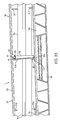
Figure 22 ,portion 14a is pivotally disposed relative to arod receiving member 50a.Portion 14b is pivotally disposed relative torod receiving member 50b.Rod receiving members openings 45a (shown inFigure 1 ), 45a' (shown inFigure 1 ) onleg 9a (shown inFigure 1 ) and 45b (shown inFigure 10 ), 45b' (shown inFigure 10 ) onleg 9b (shown inFigure 10 ), respectively, and affixedinside channels 18a (shown inFigure 13 ) and 18b (shown inFigure 13 ), respectively. Becauserod receiving members rod receiving member 50a will be discussed in detail, but the discussion applies essentially to therod receiving member 50b. Therod receiving member 50a hascurved portions 73a, 73b (partially obstructed from view byrod portion 47a androd receiving member 50a), and 73c (obstructed from view byrod portion 47a androd receiving member 50a) integrally molded with therod receiving member 50a.Curved portions shape forming recesses rod portion 47a.Rod receiving member 50a receives therod portion 47a intorecesses curved portions recesses portion 14a to be pivotally disposed relative torod receiving member 50a.Tabs openings rod receiving member 50a insidechannel 18a (shown inFigure 14 ). Thestop tab 82 forcibly engages the inner surface of thecenter rail 17a (shown inFigure 14 ) to help affixrod receiving member 50a insidechannel 18a. - In the embodiment shown in
Figure 23 ,leg pair leg pair ribs side walls Side wall 5b has integralplastic ribs Side wall 5a also hasribs legs leg pair leg pair ribs legs rib - As shown in
Figure 23 , which is a perspective view of the underside of thebody 2, alatch member 28 is pivotally connected toside wall 5a by afastener 42 and latchable to theopposite side wall 5b to further prevent the legs from pivoting from a storage position into an extended position. Thelatch member 28 is approximately the same length as distance between the inner surfaces ofside walls latch member 28 comprises anaperture 39 at one end and anabutment 40 at the other end. Theabutment 40 is integrally molded with thelatch member 28 so as to form a one-piece unitary molded structure. Theabutment 40 is perpendicular to the length of thelatch member 28. Anring 38 with anopening 41 is molded with theside wall 5a adjacent torib 21e for receiving afastener 42. Thefastener 42 is then inserted through theaperture 39 and inside theopening 41, pivotally fastening thelatch member 28 to theside wall 5a. To latch thelatch member 28 toside wall 5b, theabutment 40 is inserted into a hole 43 (partially obstructed from view) formed inrib 21 b. - In the embodiment shown in
Figure 23 , thelatch member 28 is made of plastic. The use of plastic is not intended to be limiting, and thelatch member 28 may be made of metal or any other suitable material or combination thereof as is well known in the art. - In another aspect of embodiment shown in
Figure 23 , thefolding sawhorse 1 is in a storage position.Legs 9a are 9b are partially nested within one another.Legs leg pair first side 26 are disposed parallel to theleg pair second side 27 of thefolding sawhorse 1.Leg pair Figures 8 and 9 ) towardside wall 5a. Similarly,leg pair Figures 8 and 9 ) towardside wall 5b. The pivoting ofleg pair side wall 5a andleg pair side wall 5b allows for angled storage position forlegs hypotenuse 69a (shown inFigure 11 ) ofinner ramp 30a (shown inFigure 11 ) operates to guide thelegs body 2 when in the storage position to enableleg pair first side 26 of thefolding sawhorse 1 to be positioned in a side-by-side relationship toleg pair second side 27 of thefolding sawhorse 1 when in the storage position. Similarly, another hypotenuse (not shown) of another inner ramp (not shown) onsecond side 27 operates to guide thelegs body 2 when in the storage position to enableleg pair second side 27 of thefolding sawhorse 1 to be positioned in a side-by-side relationship toleg pair first side 26 of thefolding sawhorse 1 when in the storage position. The angled orientation oflegs leg pair leg pair storage compartment 7. - In the embodiment shown in
Figures 24, 25 , and26 , theleg pair leg pair latch 12 is connected relative toside wall 6b. The connectinglatch 12 comprises a latchingportion 52, pivoting rod 53 (obstructed from view by latch retaining protrusion 54), and ahandle 56. The connectinglatch 12 enables thefolding sawhorse 1 to be latched to another folding sawhorse 1' (shown inFigures 27, 28 , and29 ). Alatch retaining protrusion 54 is molded withside wall 6b. Thelatch retaining protrusion 54 further comprises a recess or optionally a protrusion configured to pivotally connect with pivotingrod 53 so that connectinglatch 12 is pivotally disposed relative toside wall 6b. - In another aspect of the embodiment shown in
Figures 24, 25 , and26 ,latch retaining abutments side wall 6b. Latch retainingabutments lower surfaces Figures 25 and26 ), respectively, andupper surfaces portion 52. The upper surfaces 76 are curved surfaces onlatch retaining abutments 34 that are a larger distance away fromside wall 6b than the distance between lower surfaces 75 andside wall 6b. Lower surfaces 75 are concave (curved inwardly), while upper surfaces 76 are convex (curved outwardly). The latchingportion 52 must first contact upper surfaces 76 when latchingportion 52 is forcibly engaged with thelatch retaining abutments 34. - In another aspect of the embodiment shown in
Figures 24, 25 , and26 , the width dimension between latchingportion 52 and pivotingrod 53 is slightly less than the width dimension between pivotingrod 53 and upper surfaces 76. To hold the connectinglatch 12 againstside wall 6b, latchingportion 52 is forcibly engaged with the upper surfaces 76 ofleg retaining abutments 34. Because the connectinglatch 12 andleg retaining abutments 34 are both made of resilient flexible plastic material, the forcible engagement between the connectinglatch 12 and theleg retaining abutments 34 displaces the latchingportion 52 and upper surfaces 76, allowing the latchingportion 53 to contact lower surfaces 75. The contact between latchingportion 52 and lower surfaces 75 frictionally holds connectinglatch 12 alongside wall 6b (as shown inFigure 19 ). Eachlatch retaining abutment latch 12 againstside wall 6b. Essentially, the configuration described is a "snap fit" configuration where the latchingportion 52 "snap fits" withleg retaining abutments 34. This configuration prevents the connectinglatch 12 from swinging freely (shown inFigures 20 and21 ) when connectinglatch 12 is not in use. - In the embodiment shown in
Figure 27 , the connectinglatch 12 is held alongside wall 6b byleg retaining abutments 34. - In the embodiment shown in
Figure 28 ,side wall 6a haslatch receiving protrusion 64 havinglatch receiving abutments side wall 6a. Latch receivingprotrusion 64 andlatch receiving abutments 35 are essentially identical to latch retaining protrusion 54 (shown inFigures 22 ,23 and24 ) and latch retaining abutments 34 (shown inFigures 22 ,23 and24 ), respectively. The only difference betweenlatch receiving protrusion 64 andlatch retaining protrusion 54 is thatlatch retaining protrusion 54carries connecting latch 12. Becauselatch receiving abutments 35 are essentially identical to latch retaining abutments,latch receiving abutments 35 essentially operate identically to latch retainingabutments 34 to receive a connecting latch 12' (shown inFigures 29 and30 ) of another folding sawhorse 1' (shown inFigures 29 and30 ). - In the embodiment shown in
Figures 29 ,30, and 31 ,folding sawhorse 1 is placed on top of folding sawhorse 1' such that thestorage compartment 7 offolding sawhorse 1 faces the storage compartment 7' of folding sawhorse 1'. Furthermore, thefolding sawhorses 1 and 1' are aligned such that connectinglatch 12 onfolding sawhorse 1 can be latched to latch receivingabutments 35 on folding sawhorse 1'. The connectinglatch 12 offolding sawhorse 1 is then latched to thelatch receiving abutments 35 of folding sawhorse 1', and vice versa for folding sawhorse 1'. When latched together, the twofolding sawhorses 1 and 1' form a twin pack configuration 36 (as shown inFigure 26 ). Thetwin pack configuration 36 enables both foldingsawhorse 1 and 1' to be more easily carried from one place to another. - In the embodiment shown in
Figure 32 , a carryingstrap 37 is attached toside walls twin pack configuration 36 offolding sawhorses 1 and 1'. The carryingstrap 37 may be adjustable. Auser 46 can then carry thetwin pack configuration 36 from one place to another. - Although the invention has been described in detail for the purpose of illustration based on what is currently considered to be the most practical and preferred embodiments, it is to be understood that such detail is solely for that purpose and that the invention is not limited to the disclosed embodiments, but, on the contrary, is intended to cover modifications and equivalent arrangements that are within the spirit and scope of the appended claims. For example, it is to be understood that the present invention contemplates that, to the extent possible, one or more features of any embodiment may be combined with one or more features of any other embodiment.
Claims (15)
- A folding sawhorse (1), comprising:an elongate plastic body (2) having a top wall (3) with an upper work surface (4), and a plurality of side walls (5a,5b,6a,6b), the walls defining a storage compartment (7);a plurality of metal legs (9a,9b,9c,9d) that are pivotally disposed relative to the plastic body, the legs being movable between a deployed position wherein the legs are capable of supporting the plastic body in a condition for use, and a storage position in which the legs are folded so as to be substantially disposed in the storage compartment, wherein the metal legs forcibly engage with adjacent plastic surfaces (21 a,21 b,21 c,21 d,21 e,21f,69a) of the plastic body when the legs are in the deployed position.
- The folding sawhorse according to claim 1, further comprising a support rail (13a,13b), connected between a pair of the legs, the support rail comprising two portions (14a,14b), wherein each portion is pivotally disposed relative to the other portion, and wherein each portion is pivotally disposed relative to one of the pair of legs.
- The folding sawhorse according to claim 2, wherein each portion comprises ring portions (44a,44b,44a',44b') at one end.
- The folding sawhorse according to claim 3, wherein each portion further comprises first (70a,70b,70a',70b') and second (71a,71b,71a',71b') stop surfaces, wherein the first and second stop surfaces contact each other when the support rail is in a straight position.
- The folding sawhorse according to claim 4, wherein the first and second stop surfaces stop the ring portions from pivoting away from the plastic body unless a force applied to the support rail exceeds a threshold level, wherein the threshold level is greater than the force required to pivot or move the ring portions toward the plastic body.
- The folding sawhorse according to any one of the previous claims, further comprising a leg latch (28) that prevents the legs (9a,9b,9c,9d) from being moved from the storage position to the deployed position, wherein the leg latch is pivotally disposed relative to a side wall (5a) of the plastic body (2).
- The folding sawhorse according to any one of the previous claims, further comprising a connecting latch (12) that enables the sawhorse (1) to be latched to another folding sawhorse (1').
- The folding sawhorse according to claim 7, wherein the connecting latch further comprises a latching portion (52), a pivoting rod (53), and a handle (56).
- The folding sawhorse according to either on of claims 7 or 8, further comprising a latch retaining protrusion (54), wherein the latch retaining protrusion (54) further comprises a recess or optionally a protrusion configured to pivotally connect with the pivoting rod (53).
- The folding sawhorse according to any one of claims 7 to 9, wherein abutments (34a,34b,34c,34d) are molded into the outer surface of one of the sidewalls (6a,6b).
- The folding sawhorse according to claim 10, wherein each abutment has lower surfaces (75a,75b,75c,75d) and upper surfaces (76a,76b,76c,76d), wherein the lower surfaces are curved surfaces configured for receiving the latch portion, wherein the latching portion must first contact upper surfaces (76a,76b,76c,76d) when the latching portion is forcibly engaged with the abutments.
- The folding sawhorse according to any one of the previous claims, wherein the plastic surfaces (21a,21b,21c,21d,21e,21f,69a) extend inwardly from the sidewalls towards the storage compartment (7), wherein the plastic surfaces comprise regions that forcibly engage the legs when in the storage position.
- The folding sawhorse according to claim 12, wherein the plastic surfaces operate to guide the legs (9a,9b,9c,9d) to have an angled orientation relative to a central longitudinal axis of the body when in the storage position to enable a pair of the legs (9a,9b) connected to one side (26) of the sawhorse to be positioned in side-by-side relationship to a pair of the legs (9c,9d) connected to an opposite side (27) of the sawhorse when in the storage position.
- The folding sawhorse according to claim 13, wherein when in the storage position, the pair of legs (9a,9b) connected to one side (26) of the sawhorse are at least partially nested within one another, and the pair of legs (9c,9d) connected to the opposite side (27) of the sawhorse are at least partially nested within one another.
- The folding sawhorse according to any one of claims 12 to 14, wherein the plastic body (2) has ribs (21 a,21 b,21 c,21 d,21 e,21f) integrally molded with the inner surfaces of the side walls (5a,5b), wherein when in the storage position, both pairs of legs (9a,9b,9c,9d) forcibly engage the ribs (21 c,21 b,21 c,21 d,21 e,21f), displacing the plastic material slightly, so that pair of legs remain in the storage position.
Applications Claiming Priority (1)
| Application Number | Priority Date | Filing Date | Title |
|---|---|---|---|
| US12/467,147 US10343274B2 (en) | 2009-05-15 | 2009-05-15 | Folding sawhorse |
Publications (2)
| Publication Number | Publication Date |
|---|---|
| EP2251155A1 true EP2251155A1 (en) | 2010-11-17 |
| EP2251155B1 EP2251155B1 (en) | 2020-01-01 |
Family
ID=42562642
Family Applications (1)
| Application Number | Title | Priority Date | Filing Date |
|---|---|---|---|
| EP10162878.2A Active EP2251155B1 (en) | 2009-05-15 | 2010-05-14 | Folding sawhorse |
Country Status (5)
| Country | Link |
|---|---|
| US (1) | US10343274B2 (en) |
| EP (1) | EP2251155B1 (en) |
| AU (1) | AU2010201808A1 (en) |
| CA (1) | CA2702411C (en) |
| IL (1) | IL205520A (en) |
Cited By (6)
| Publication number | Priority date | Publication date | Assignee | Title |
|---|---|---|---|---|
| GB2484308A (en) * | 2010-10-06 | 2012-04-11 | Christopher Matthew Irwin | Frame for a display device |
| EP2450156A1 (en) * | 2010-11-05 | 2012-05-09 | Black & Decker Inc. | Collapsible saw horses |
| CN105563436A (en) * | 2014-10-14 | 2016-05-11 | 苏州宝时得电动工具有限公司 | Workbench |
| WO2016126765A1 (en) * | 2015-02-03 | 2016-08-11 | Affinity Tool Works, Llc | Tool stand with automatically deployable legs |
| WO2018005734A1 (en) * | 2016-06-29 | 2018-01-04 | Affinity Tool Works, Llc | Saw horse having quick release deployable supports |
| EP3266351A1 (en) * | 2016-07-06 | 2018-01-10 | Ingenieurbuero consult+control Dr. -Ing. J. Westhaeusler | Assembly for positioning backpacks |
Families Citing this family (35)
| Publication number | Priority date | Publication date | Assignee | Title |
|---|---|---|---|---|
| CN107405768A (en) * | 2015-02-03 | 2017-11-28 | 亲和工具工程有限公司 | With can Automatic-expanding leg tool rack |
| USD783319S1 (en) * | 2015-06-03 | 2017-04-11 | Knoll, Inc. | Article of furniture |
| CA167908S (en) * | 2015-10-16 | 2017-01-20 | Stanley Works Israel | Folding sawhorse |
| EP3156191B1 (en) * | 2015-10-16 | 2021-09-01 | The Stanley Works Israel Ltd. | Sawhorse |
| US20240058942A1 (en) * | 2016-01-26 | 2024-02-22 | Perfect Site LLC | Sawhorse |
| US10815680B2 (en) * | 2016-03-22 | 2020-10-27 | Werner Co. | Apparatus having a handle on which a user stands, and method |
| USD791343S1 (en) * | 2016-06-30 | 2017-07-04 | Creative Plastics Concepts, Llc | Extended sawhorse |
| US10239470B2 (en) * | 2016-09-15 | 2019-03-26 | Ford Global Technologies, Llc | Vehicle with an integrated sawhorse |
| US11084163B2 (en) | 2016-11-16 | 2021-08-10 | Kreg Enterprises, Inc. | Mobile project center system |
| USD842015S1 (en) | 2016-11-16 | 2019-03-05 | Kreg Enterprises, Inc. | Mobile and collapsible workbench |
| US10875172B2 (en) | 2017-04-07 | 2020-12-29 | Creative Plastic Concepts, Llc | Extended sawhorse with folding supports |
| US10864625B2 (en) * | 2017-12-05 | 2020-12-15 | Js Products, Inc. | Sawhorse |
| US11193628B2 (en) * | 2018-01-24 | 2021-12-07 | Gary C. Hoyle | Collapsible leg assembly for self-leveling devices |
| USD868509S1 (en) * | 2018-05-23 | 2019-12-03 | Herman Miller, Inc. | Chase |
| USD925065S1 (en) | 2018-06-22 | 2021-07-13 | Kreg Enterprises, Inc. | Track horse |
| US10919141B2 (en) * | 2018-07-13 | 2021-02-16 | The Stanley Works Israel Ltd. | Container with stool in lid |
| US10377032B1 (en) * | 2018-09-13 | 2019-08-13 | Yariv Kadosh | Sawhorse table with a quick lock-release mechanism |
| USD878119S1 (en) * | 2018-10-31 | 2020-03-17 | WeWork Companies Inc. | Structural support |
| CN211333078U (en) | 2019-10-09 | 2020-08-25 | 金华市渤蓝科技有限公司 | Multifunctional workbench |
| US12350810B2 (en) * | 2019-10-10 | 2025-07-08 | Perfect Site LLC | Work stand and work stand features |
| US11648659B2 (en) | 2019-10-10 | 2023-05-16 | Perfect Site LLC | Work support |
| US11260523B2 (en) * | 2020-04-09 | 2022-03-01 | Nhon Hoa Nguyen | Height adjustable workstand support |
| US12570022B2 (en) | 2020-10-22 | 2026-03-10 | Js Products, Inc. | Hybrid sawhorse |
| US12005564B2 (en) | 2020-10-22 | 2024-06-11 | Js Products, Inc. | Hybrid clamp and clamping sawhorse |
| US12459155B2 (en) | 2020-10-22 | 2025-11-04 | Js Products, Inc. | Light duty sawhorse |
| US12565779B2 (en) | 2021-10-28 | 2026-03-03 | Werner Co. | Work platform and method |
| US20230132551A1 (en) * | 2021-11-03 | 2023-05-04 | Kammok Holdings, Llc | Asymmetrical portable hammock stand |
| US20230294267A1 (en) * | 2022-03-16 | 2023-09-21 | Robbie Dupin | Sawhorse Device |
| US11883945B2 (en) | 2022-04-12 | 2024-01-30 | Michael H Panosian | Foldable workbench |
| US11912477B2 (en) | 2022-06-08 | 2024-02-27 | Yeti Coolers, Llc | Container with handle and latching system |
| USD1024557S1 (en) | 2022-06-08 | 2024-04-30 | Yeti Coolers, Llc | Container |
| USD1063376S1 (en) | 2022-06-08 | 2025-02-25 | Yeti Coolers, Llc | Container |
| USD1036116S1 (en) | 2022-06-08 | 2024-07-23 | Yeti Coolers, Llc | Container |
| WO2024097937A1 (en) * | 2022-11-03 | 2024-05-10 | Affinity Tool Works, Llc | Quick release saw horse with side independent folding legs |
| USD1036119S1 (en) | 2022-11-30 | 2024-07-23 | Yeti Coolers, Llc | Container |
Citations (8)
| Publication number | Priority date | Publication date | Assignee | Title |
|---|---|---|---|---|
| US4711319A (en) * | 1986-12-19 | 1987-12-08 | Carmelo Sansotta | Saw horse |
| DE29818873U1 (en) * | 1998-10-22 | 2000-03-02 | Ransberger, Hans, 83737 Irschenberg | Kit for a bearing block and socket unit of this bearing block |
| DE20006881U1 (en) * | 2000-04-14 | 2000-07-20 | Mafell AG, 78727 Oberndorf | Table saw base |
| US6286824B1 (en) * | 1999-11-01 | 2001-09-11 | Keter Plastic Ltd. | Collapsible worktable |
| WO2002060649A2 (en) * | 2000-12-18 | 2002-08-08 | Zag Industries, Ltd. | Portable support assembly for a workpiece |
| NL1023576C1 (en) * | 2003-05-30 | 2004-12-01 | Printmaster Holland C V | Portable workbench with two part worktop, has undercarriage comprising two separate units for supporting worktop |
| US20050115768A1 (en) * | 2003-10-29 | 2005-06-02 | Jim Frey | Knock down sawhorse |
| US20060289320A1 (en) * | 2005-06-27 | 2006-12-28 | Miller Norma J | Multi-functional utility system |
Family Cites Families (74)
| Publication number | Priority date | Publication date | Assignee | Title |
|---|---|---|---|---|
| US1450869A (en) * | 1920-04-30 | 1923-04-03 | Reinelt William Wesley | Carpenter's folding sawhorse |
| US1476855A (en) * | 1921-05-06 | 1923-12-11 | William C Clark | Collapsible sawhorse |
| US1479209A (en) * | 1922-03-14 | 1924-01-01 | William C Clark | Collapsible sawhorse |
| US1656558A (en) * | 1927-05-02 | 1928-01-17 | Floyd Allen | Metal horse |
| US1778566A (en) * | 1928-02-13 | 1930-10-14 | Trav Ler Mfg Corp | Trestle |
| US2216187A (en) * | 1939-09-07 | 1940-10-01 | Dion Hector | Trestle or horse |
| US2396737A (en) * | 1945-05-18 | 1946-03-19 | Maclaskey John | Sawhorse |
| US2473342A (en) * | 1946-05-17 | 1949-06-14 | Charles O Larson | Folding sawhorse |
| US2824771A (en) * | 1954-04-19 | 1958-02-25 | Fred Riefschneider | Foldable sawhorse |
| US2832648A (en) * | 1956-06-25 | 1958-04-29 | Herman W Goosmann | Trestles |
| US3198286A (en) * | 1962-12-03 | 1965-08-03 | Homer M Wilson | Folding sawhorse |
| US3269487A (en) * | 1964-11-09 | 1966-08-30 | Larson Co Charles O | Saw horse structure |
| US3286788A (en) * | 1965-06-14 | 1966-11-22 | Bank Of America Nat Trust & Savings Ass | Sawhorse or trestle |
| US3481430A (en) * | 1968-02-29 | 1969-12-02 | Francis K Solomon | Folding portable sawhorse |
| US3616873A (en) * | 1970-01-14 | 1971-11-02 | John Kehrig | Foldaway sawhorse |
| US3631941A (en) * | 1970-04-01 | 1972-01-04 | Porta Horse Inc | Collapsible sawhorse |
| US3637045A (en) * | 1970-04-29 | 1972-01-25 | Donald E Poffenbaugh | Knockdown sawhorse |
| US3618704A (en) * | 1970-08-07 | 1971-11-09 | James A Smith Sr | Folding leg bracket for sawhorse |
| US3633709A (en) * | 1970-08-31 | 1972-01-11 | Wilton C Weser | Foldable sawhorse |
| US3682272A (en) * | 1970-12-07 | 1972-08-08 | Arthur Secor | Foldable sawhorse |
| US3722621A (en) * | 1971-06-01 | 1973-03-27 | M Jones | Ladder bench |
| US3810527A (en) * | 1973-08-02 | 1974-05-14 | J Kramer | Foldable sawhorse |
| US3951233A (en) * | 1975-09-22 | 1976-04-20 | Daniel Meyers | Collapsible sawhorse |
| US4030565A (en) * | 1975-12-03 | 1977-06-21 | Reynald Chaput | Collapsible sawhorse package |
| US4191111A (en) * | 1978-01-17 | 1980-03-04 | Emmert Raymond L | Bench folding leg and brace structure |
| US4296834A (en) * | 1979-06-01 | 1981-10-27 | Walter Kroger | Folding sawhorse |
| US4319663A (en) * | 1980-05-22 | 1982-03-16 | Barden Dan E | Portable sawhorse |
| US4403678A (en) * | 1981-11-02 | 1983-09-13 | Mansion Industries, Inc. | Folding saw horse |
| US4489808A (en) * | 1983-10-24 | 1984-12-25 | Voye Bradford D | Collapsible sawhorse |
| US4496028A (en) * | 1984-02-21 | 1985-01-29 | Peterson Theodore A | Instant sawhorse |
| US4880008A (en) * | 1985-05-08 | 1989-11-14 | The General Hospital Corporation | Vivo enhancement of NMR relaxivity |
| US4605099A (en) * | 1985-05-17 | 1986-08-12 | Crum Wesley W | Bracket means providing full collapsibility to sawhorses |
| US4964877A (en) * | 1986-01-14 | 1990-10-23 | Wilson Greatbatch Ltd. | Non-aqueous lithium battery |
| US4640386A (en) * | 1986-02-14 | 1987-02-03 | Hall James W | Folding utility horse |
| US4645162A (en) * | 1986-02-25 | 1987-02-24 | Bertrand Roy | Leg support structure |
| US4804064A (en) * | 1987-08-13 | 1989-02-14 | Variety International, Inc. | Adjustable, collapsible sawhorse |
| US4730698A (en) * | 1987-09-28 | 1988-03-15 | Harris James E | Foldable sawhorse |
| US4771863A (en) * | 1987-10-05 | 1988-09-20 | Stansberry Robert F | Saw horse construction |
| US4880080A (en) * | 1988-10-24 | 1989-11-14 | Brockman Lester H | Collapsible sawhorse |
| US4884658A (en) * | 1988-10-24 | 1989-12-05 | Banfield William A | Collapsible sawhorse |
| US4967877A (en) | 1990-01-16 | 1990-11-06 | Cfh Corporation | Folding sawhorse |
| US5052517A (en) * | 1990-01-05 | 1991-10-01 | Cfh Corporation | Folding sawhorse |
| US5007502A (en) * | 1990-07-16 | 1991-04-16 | Alan F. Shapiro | Self-leveling saw horse |
| USD328355S (en) * | 1990-11-02 | 1992-07-28 | Worldwide Manufacturing, Inc. | Folding sawhorse |
| US5125478A (en) * | 1991-02-14 | 1992-06-30 | Henningsen Ralph J | Folding sawhorse |
| US5119903A (en) * | 1991-05-13 | 1992-06-09 | Ulshafer Jr Carl | Collapsible sawhorse apparatus |
| US5096019A (en) * | 1991-08-29 | 1992-03-17 | Kelsay Daniel G | Folding sawhorse |
| US5297655A (en) * | 1992-09-24 | 1994-03-29 | Wolfe Danny K | Collapsible sawhorse |
| US5439073A (en) * | 1992-10-30 | 1995-08-08 | Johnson; Richard | Foldaway splay-legged stand |
| US5421430A (en) * | 1993-11-15 | 1995-06-06 | Cox; George | Collapsible sawhorse |
| US5467842A (en) * | 1994-12-29 | 1995-11-21 | Meloy; John | Collapsible saw horse |
| US5704450A (en) * | 1995-09-18 | 1998-01-06 | Lunceford; Harvey | Portable and foldable workhorse |
| US5628382A (en) * | 1995-09-29 | 1997-05-13 | Hill; Dennis R. | Collapsible sawhorse |
| US5779003A (en) * | 1997-01-14 | 1998-07-14 | Carty; Walter F. | Collapsible sawhorse |
| US6129180A (en) * | 1997-04-28 | 2000-10-10 | Brady; Troy S. | Sawhorse |
| US5782279A (en) * | 1997-05-23 | 1998-07-21 | Stecker, Sr.; David W. | Portable universal saw table |
| USD409764S (en) * | 1998-04-14 | 1999-05-11 | American Manufacturing Company, Inc. | Cross member for a sawhorse |
| IL125793A (en) * | 1998-08-14 | 2003-05-29 | Z A G Ind Ltd | Height and working width adjustable sawhorse |
| US6092627A (en) * | 1998-09-16 | 2000-07-25 | Burger; Richard | Stowable knockdown sawhorse |
| US6019193A (en) * | 1999-07-13 | 2000-02-01 | Brown; Barbara M. | Sawhorse system |
| US6302323B1 (en) * | 1999-10-22 | 2001-10-16 | Packaging Corporation Of America | Displayable produce container and method for making the same |
| GB2358131A (en) * | 2000-01-11 | 2001-07-18 | Innovations For Trade And Tech | Step-stool |
| JP2001291651A (en) * | 2000-04-05 | 2001-10-19 | Nec Corp | Method of forming resist pattern and method of manufacturing semiconductor device |
| US20020011381A1 (en) * | 2000-04-21 | 2002-01-31 | Destre Wilkerson | Foldable sawhorse |
| US6564903B2 (en) | 2000-08-14 | 2003-05-20 | Russell S. Krajec | Collapsable sawhorse bracket with interleaving legs |
| US6681895B2 (en) * | 2000-08-22 | 2004-01-27 | Keith David Virtue | Pivotal leg assembly |
| US20020152934A1 (en) * | 2001-04-20 | 2002-10-24 | Thayne Haney | Screw bosses for blow-molded structures |
| US6601675B2 (en) * | 2001-05-10 | 2003-08-05 | Donald P. Gulledge | Locking foldable sawhorse |
| US6705796B2 (en) * | 2001-11-26 | 2004-03-16 | Cortina Tool & Molding Co. | Barricades and methods of making same |
| CA2460472A1 (en) * | 2004-03-09 | 2005-09-09 | Stefano Slavich | Knock down sawhorse |
| US7240705B2 (en) * | 2005-01-24 | 2007-07-10 | Toby Alger | Table for portable miter saws |
| US7185738B1 (en) * | 2005-04-12 | 2007-03-06 | Jerry Clepper | Modular saw horse |
| USD634858S1 (en) * | 2010-08-12 | 2011-03-22 | The Stanley Works Israel Ltd. | Sawhorse |
| USD634857S1 (en) * | 2010-08-12 | 2011-03-22 | The Stanley Works Israel Ltd. | Sawhorse |
-
2009
- 2009-05-15 US US12/467,147 patent/US10343274B2/en active Active
-
2010
- 2010-05-03 IL IL205520A patent/IL205520A/en active IP Right Grant
- 2010-05-06 CA CA2702411A patent/CA2702411C/en not_active Expired - Fee Related
- 2010-05-06 AU AU2010201808A patent/AU2010201808A1/en not_active Abandoned
- 2010-05-14 EP EP10162878.2A patent/EP2251155B1/en active Active
Patent Citations (8)
| Publication number | Priority date | Publication date | Assignee | Title |
|---|---|---|---|---|
| US4711319A (en) * | 1986-12-19 | 1987-12-08 | Carmelo Sansotta | Saw horse |
| DE29818873U1 (en) * | 1998-10-22 | 2000-03-02 | Ransberger, Hans, 83737 Irschenberg | Kit for a bearing block and socket unit of this bearing block |
| US6286824B1 (en) * | 1999-11-01 | 2001-09-11 | Keter Plastic Ltd. | Collapsible worktable |
| DE20006881U1 (en) * | 2000-04-14 | 2000-07-20 | Mafell AG, 78727 Oberndorf | Table saw base |
| WO2002060649A2 (en) * | 2000-12-18 | 2002-08-08 | Zag Industries, Ltd. | Portable support assembly for a workpiece |
| NL1023576C1 (en) * | 2003-05-30 | 2004-12-01 | Printmaster Holland C V | Portable workbench with two part worktop, has undercarriage comprising two separate units for supporting worktop |
| US20050115768A1 (en) * | 2003-10-29 | 2005-06-02 | Jim Frey | Knock down sawhorse |
| US20060289320A1 (en) * | 2005-06-27 | 2006-12-28 | Miller Norma J | Multi-functional utility system |
Cited By (10)
| Publication number | Priority date | Publication date | Assignee | Title |
|---|---|---|---|---|
| GB2484308A (en) * | 2010-10-06 | 2012-04-11 | Christopher Matthew Irwin | Frame for a display device |
| EP2450156A1 (en) * | 2010-11-05 | 2012-05-09 | Black & Decker Inc. | Collapsible saw horses |
| US8439165B2 (en) | 2010-11-05 | 2013-05-14 | Black & Decker Inc. | Collapsible saw horses |
| CN105563436A (en) * | 2014-10-14 | 2016-05-11 | 苏州宝时得电动工具有限公司 | Workbench |
| WO2016126765A1 (en) * | 2015-02-03 | 2016-08-11 | Affinity Tool Works, Llc | Tool stand with automatically deployable legs |
| AU2016215378B2 (en) * | 2015-02-03 | 2020-12-10 | Affinity Tool Works, Llc | Tool stand with automatically deployable legs |
| WO2018005734A1 (en) * | 2016-06-29 | 2018-01-04 | Affinity Tool Works, Llc | Saw horse having quick release deployable supports |
| US10549417B2 (en) | 2016-06-29 | 2020-02-04 | Affinity Tool Works, Llc | Saw horse having quick release deployable supports |
| AU2017290723B2 (en) * | 2016-06-29 | 2023-02-16 | Affinity Tool Works, Llc | Saw horse having quick release deployable supports |
| EP3266351A1 (en) * | 2016-07-06 | 2018-01-10 | Ingenieurbuero consult+control Dr. -Ing. J. Westhaeusler | Assembly for positioning backpacks |
Also Published As
| Publication number | Publication date |
|---|---|
| EP2251155B1 (en) | 2020-01-01 |
| AU2010201808A1 (en) | 2010-12-02 |
| IL205520A (en) | 2015-07-30 |
| US20100288585A1 (en) | 2010-11-18 |
| US10343274B2 (en) | 2019-07-09 |
| CA2702411C (en) | 2019-03-12 |
| CA2702411A1 (en) | 2010-11-15 |
| IL205520A0 (en) | 2010-12-30 |
Similar Documents
| Publication | Publication Date | Title |
|---|---|---|
| EP2251155B1 (en) | Folding sawhorse | |
| US20230241760A1 (en) | Tool Storage Device | |
| EP3747603B1 (en) | Stacking latch mechanism | |
| EP2133180B1 (en) | A tool container assembly | |
| US7922058B2 (en) | Nail gun with an angle-adjustable magazine | |
| CA2412677C (en) | Tool frame member including spring | |
| TWI402202B (en) | Integrated storage system with locking containers | |
| US9539722B2 (en) | Tool storage devices | |
| JP4923513B2 (en) | Vehicle seat slide device | |
| US20120228171A1 (en) | Tool case for engaging a ladder | |
| CA2314044C (en) | Adjustable sawhorse | |
| US8636144B1 (en) | Ladder tool tray with separable paint bucket | |
| EP2450156A1 (en) | Collapsible saw horses | |
| US20230098490A1 (en) | Accessory mount system for use with elevated work platforms | |
| EP1716981A2 (en) | Tool holder insert for storage container | |
| EP3778135A1 (en) | Convertible sawhorse and work table | |
| US12134180B2 (en) | Modular tool container | |
| US6592310B2 (en) | Tie-down hoop | |
| US7513364B2 (en) | Casing with a locking unit | |
| WO2015035211A2 (en) | Adjustable ladders, ladder components and related methods | |
| AU2022213427B2 (en) | Top cap for articulating ladder | |
| GB2483560A (en) | Bassinet with handle | |
| US20150174757A1 (en) | Operating rod assembly for a toolbox | |
| US20140305980A1 (en) | Vehicle accessory retaining system | |
| WO2023150501A1 (en) | Tool storage device |
Legal Events
| Date | Code | Title | Description |
|---|---|---|---|
| PUAI | Public reference made under article 153(3) epc to a published international application that has entered the european phase |
Free format text: ORIGINAL CODE: 0009012 |
|
| AK | Designated contracting states |
Kind code of ref document: A1 Designated state(s): AL AT BE BG CH CY CZ DE DK EE ES FI FR GB GR HR HU IE IS IT LI LT LU LV MC MK MT NL NO PL PT RO SE SI SK SM TR |
|
| AX | Request for extension of the european patent |
Extension state: BA ME RS |
|
| 17P | Request for examination filed |
Effective date: 20101129 |
|
| RIN1 | Information on inventor provided before grant (corrected) |
Inventor name: KATZ, AMIR Inventor name: LANDAU, EITAN |
|
| 17Q | First examination report despatched |
Effective date: 20160610 |
|
| STAA | Information on the status of an ep patent application or granted ep patent |
Free format text: STATUS: EXAMINATION IS IN PROGRESS |
|
| GRAP | Despatch of communication of intention to grant a patent |
Free format text: ORIGINAL CODE: EPIDOSNIGR1 |
|
| STAA | Information on the status of an ep patent application or granted ep patent |
Free format text: STATUS: GRANT OF PATENT IS INTENDED |
|
| INTG | Intention to grant announced |
Effective date: 20190910 |
|
| GRAS | Grant fee paid |
Free format text: ORIGINAL CODE: EPIDOSNIGR3 |
|
| GRAA | (expected) grant |
Free format text: ORIGINAL CODE: 0009210 |
|
| STAA | Information on the status of an ep patent application or granted ep patent |
Free format text: STATUS: THE PATENT HAS BEEN GRANTED |
|
| AK | Designated contracting states |
Kind code of ref document: B1 Designated state(s): AL AT BE BG CH CY CZ DE DK EE ES FI FR GB GR HR HU IE IS IT LI LT LU LV MC MK MT NL NO PL PT RO SE SI SK SM TR |
|
| REG | Reference to a national code |
Ref country code: GB Ref legal event code: FG4D |
|
| REG | Reference to a national code |
Ref country code: AT Ref legal event code: REF Ref document number: 1219195 Country of ref document: AT Kind code of ref document: T Effective date: 20200115 Ref country code: CH Ref legal event code: EP |
|
| REG | Reference to a national code |
Ref country code: IE Ref legal event code: FG4D |
|
| REG | Reference to a national code |
Ref country code: DE Ref legal event code: R096 Ref document number: 602010062593 Country of ref document: DE |
|
| REG | Reference to a national code |
Ref country code: NL Ref legal event code: MP Effective date: 20200101 |
|
| REG | Reference to a national code |
Ref country code: LT Ref legal event code: MG4D |
|
| PG25 | Lapsed in a contracting state [announced via postgrant information from national office to epo] |
Ref country code: LT Free format text: LAPSE BECAUSE OF FAILURE TO SUBMIT A TRANSLATION OF THE DESCRIPTION OR TO PAY THE FEE WITHIN THE PRESCRIBED TIME-LIMIT Effective date: 20200101 Ref country code: PT Free format text: LAPSE BECAUSE OF FAILURE TO SUBMIT A TRANSLATION OF THE DESCRIPTION OR TO PAY THE FEE WITHIN THE PRESCRIBED TIME-LIMIT Effective date: 20200527 Ref country code: NL Free format text: LAPSE BECAUSE OF FAILURE TO SUBMIT A TRANSLATION OF THE DESCRIPTION OR TO PAY THE FEE WITHIN THE PRESCRIBED TIME-LIMIT Effective date: 20200101 Ref country code: CZ Free format text: LAPSE BECAUSE OF FAILURE TO SUBMIT A TRANSLATION OF THE DESCRIPTION OR TO PAY THE FEE WITHIN THE PRESCRIBED TIME-LIMIT Effective date: 20200101 Ref country code: FI Free format text: LAPSE BECAUSE OF FAILURE TO SUBMIT A TRANSLATION OF THE DESCRIPTION OR TO PAY THE FEE WITHIN THE PRESCRIBED TIME-LIMIT Effective date: 20200101 Ref country code: NO Free format text: LAPSE BECAUSE OF FAILURE TO SUBMIT A TRANSLATION OF THE DESCRIPTION OR TO PAY THE FEE WITHIN THE PRESCRIBED TIME-LIMIT Effective date: 20200401 |
|
| PGFP | Annual fee paid to national office [announced via postgrant information from national office to epo] |
Ref country code: FR Payment date: 20200414 Year of fee payment: 11 |
|
| PG25 | Lapsed in a contracting state [announced via postgrant information from national office to epo] |
Ref country code: IS Free format text: LAPSE BECAUSE OF FAILURE TO SUBMIT A TRANSLATION OF THE DESCRIPTION OR TO PAY THE FEE WITHIN THE PRESCRIBED TIME-LIMIT Effective date: 20200501 Ref country code: LV Free format text: LAPSE BECAUSE OF FAILURE TO SUBMIT A TRANSLATION OF THE DESCRIPTION OR TO PAY THE FEE WITHIN THE PRESCRIBED TIME-LIMIT Effective date: 20200101 Ref country code: SE Free format text: LAPSE BECAUSE OF FAILURE TO SUBMIT A TRANSLATION OF THE DESCRIPTION OR TO PAY THE FEE WITHIN THE PRESCRIBED TIME-LIMIT Effective date: 20200101 Ref country code: BG Free format text: LAPSE BECAUSE OF FAILURE TO SUBMIT A TRANSLATION OF THE DESCRIPTION OR TO PAY THE FEE WITHIN THE PRESCRIBED TIME-LIMIT Effective date: 20200401 Ref country code: HR Free format text: LAPSE BECAUSE OF FAILURE TO SUBMIT A TRANSLATION OF THE DESCRIPTION OR TO PAY THE FEE WITHIN THE PRESCRIBED TIME-LIMIT Effective date: 20200101 Ref country code: GR Free format text: LAPSE BECAUSE OF FAILURE TO SUBMIT A TRANSLATION OF THE DESCRIPTION OR TO PAY THE FEE WITHIN THE PRESCRIBED TIME-LIMIT Effective date: 20200402 |
|
| REG | Reference to a national code |
Ref country code: DE Ref legal event code: R097 Ref document number: 602010062593 Country of ref document: DE |
|
| PG25 | Lapsed in a contracting state [announced via postgrant information from national office to epo] |
Ref country code: ES Free format text: LAPSE BECAUSE OF FAILURE TO SUBMIT A TRANSLATION OF THE DESCRIPTION OR TO PAY THE FEE WITHIN THE PRESCRIBED TIME-LIMIT Effective date: 20200101 Ref country code: SK Free format text: LAPSE BECAUSE OF FAILURE TO SUBMIT A TRANSLATION OF THE DESCRIPTION OR TO PAY THE FEE WITHIN THE PRESCRIBED TIME-LIMIT Effective date: 20200101 Ref country code: EE Free format text: LAPSE BECAUSE OF FAILURE TO SUBMIT A TRANSLATION OF THE DESCRIPTION OR TO PAY THE FEE WITHIN THE PRESCRIBED TIME-LIMIT Effective date: 20200101 Ref country code: SM Free format text: LAPSE BECAUSE OF FAILURE TO SUBMIT A TRANSLATION OF THE DESCRIPTION OR TO PAY THE FEE WITHIN THE PRESCRIBED TIME-LIMIT Effective date: 20200101 Ref country code: DK Free format text: LAPSE BECAUSE OF FAILURE TO SUBMIT A TRANSLATION OF THE DESCRIPTION OR TO PAY THE FEE WITHIN THE PRESCRIBED TIME-LIMIT Effective date: 20200101 Ref country code: RO Free format text: LAPSE BECAUSE OF FAILURE TO SUBMIT A TRANSLATION OF THE DESCRIPTION OR TO PAY THE FEE WITHIN THE PRESCRIBED TIME-LIMIT Effective date: 20200101 |
|
| PLBE | No opposition filed within time limit |
Free format text: ORIGINAL CODE: 0009261 |
|
| STAA | Information on the status of an ep patent application or granted ep patent |
Free format text: STATUS: NO OPPOSITION FILED WITHIN TIME LIMIT |
|
| REG | Reference to a national code |
Ref country code: AT Ref legal event code: MK05 Ref document number: 1219195 Country of ref document: AT Kind code of ref document: T Effective date: 20200101 |
|
| 26N | No opposition filed |
Effective date: 20201002 |
|
| PG25 | Lapsed in a contracting state [announced via postgrant information from national office to epo] |
Ref country code: MC Free format text: LAPSE BECAUSE OF FAILURE TO SUBMIT A TRANSLATION OF THE DESCRIPTION OR TO PAY THE FEE WITHIN THE PRESCRIBED TIME-LIMIT Effective date: 20200101 Ref country code: CH Free format text: LAPSE BECAUSE OF NON-PAYMENT OF DUE FEES Effective date: 20200531 Ref country code: AT Free format text: LAPSE BECAUSE OF FAILURE TO SUBMIT A TRANSLATION OF THE DESCRIPTION OR TO PAY THE FEE WITHIN THE PRESCRIBED TIME-LIMIT Effective date: 20200101 Ref country code: LI Free format text: LAPSE BECAUSE OF NON-PAYMENT OF DUE FEES Effective date: 20200531 Ref country code: IT Free format text: LAPSE BECAUSE OF FAILURE TO SUBMIT A TRANSLATION OF THE DESCRIPTION OR TO PAY THE FEE WITHIN THE PRESCRIBED TIME-LIMIT Effective date: 20200101 |
|
| PG25 | Lapsed in a contracting state [announced via postgrant information from national office to epo] |
Ref country code: SI Free format text: LAPSE BECAUSE OF FAILURE TO SUBMIT A TRANSLATION OF THE DESCRIPTION OR TO PAY THE FEE WITHIN THE PRESCRIBED TIME-LIMIT Effective date: 20200101 Ref country code: PL Free format text: LAPSE BECAUSE OF FAILURE TO SUBMIT A TRANSLATION OF THE DESCRIPTION OR TO PAY THE FEE WITHIN THE PRESCRIBED TIME-LIMIT Effective date: 20200101 |
|
| REG | Reference to a national code |
Ref country code: BE Ref legal event code: MM Effective date: 20200531 |
|
| PG25 | Lapsed in a contracting state [announced via postgrant information from national office to epo] |
Ref country code: LU Free format text: LAPSE BECAUSE OF NON-PAYMENT OF DUE FEES Effective date: 20200514 |
|
| PG25 | Lapsed in a contracting state [announced via postgrant information from national office to epo] |
Ref country code: IE Free format text: LAPSE BECAUSE OF NON-PAYMENT OF DUE FEES Effective date: 20200514 |
|
| PG25 | Lapsed in a contracting state [announced via postgrant information from national office to epo] |
Ref country code: BE Free format text: LAPSE BECAUSE OF NON-PAYMENT OF DUE FEES Effective date: 20200531 |
|
| PG25 | Lapsed in a contracting state [announced via postgrant information from national office to epo] |
Ref country code: TR Free format text: LAPSE BECAUSE OF FAILURE TO SUBMIT A TRANSLATION OF THE DESCRIPTION OR TO PAY THE FEE WITHIN THE PRESCRIBED TIME-LIMIT Effective date: 20200101 Ref country code: MT Free format text: LAPSE BECAUSE OF FAILURE TO SUBMIT A TRANSLATION OF THE DESCRIPTION OR TO PAY THE FEE WITHIN THE PRESCRIBED TIME-LIMIT Effective date: 20200101 Ref country code: FR Free format text: LAPSE BECAUSE OF NON-PAYMENT OF DUE FEES Effective date: 20210531 Ref country code: CY Free format text: LAPSE BECAUSE OF FAILURE TO SUBMIT A TRANSLATION OF THE DESCRIPTION OR TO PAY THE FEE WITHIN THE PRESCRIBED TIME-LIMIT Effective date: 20200101 |
|
| PG25 | Lapsed in a contracting state [announced via postgrant information from national office to epo] |
Ref country code: MK Free format text: LAPSE BECAUSE OF FAILURE TO SUBMIT A TRANSLATION OF THE DESCRIPTION OR TO PAY THE FEE WITHIN THE PRESCRIBED TIME-LIMIT Effective date: 20200101 Ref country code: AL Free format text: LAPSE BECAUSE OF FAILURE TO SUBMIT A TRANSLATION OF THE DESCRIPTION OR TO PAY THE FEE WITHIN THE PRESCRIBED TIME-LIMIT Effective date: 20200101 |
|
| PGFP | Annual fee paid to national office [announced via postgrant information from national office to epo] |
Ref country code: DE Payment date: 20250519 Year of fee payment: 16 |
|
| PGFP | Annual fee paid to national office [announced via postgrant information from national office to epo] |
Ref country code: GB Payment date: 20260324 Year of fee payment: 17 |