EP2250737B1 - Cable redundancy with a networked system - Google Patents
Cable redundancy with a networked system Download PDFInfo
- Publication number
- EP2250737B1 EP2250737B1 EP08869019.3A EP08869019A EP2250737B1 EP 2250737 B1 EP2250737 B1 EP 2250737B1 EP 08869019 A EP08869019 A EP 08869019A EP 2250737 B1 EP2250737 B1 EP 2250737B1
- Authority
- EP
- European Patent Office
- Prior art keywords
- port
- transmission route
- operational
- adapter
- message
- Prior art date
- Legal status (The legal status is an assumption and is not a legal conclusion. Google has not performed a legal analysis and makes no representation as to the accuracy of the status listed.)
- Not-in-force
Links
- 230000005540 biological transmission Effects 0.000 claims description 90
- 239000000872 buffer Substances 0.000 claims description 23
- 238000000034 method Methods 0.000 claims description 8
- 230000008859 change Effects 0.000 claims description 3
- 238000004891 communication Methods 0.000 description 12
- 101100513046 Neurospora crassa (strain ATCC 24698 / 74-OR23-1A / CBS 708.71 / DSM 1257 / FGSC 987) eth-1 gene Proteins 0.000 description 8
- 238000011084 recovery Methods 0.000 description 6
- 230000002159 abnormal effect Effects 0.000 description 4
- 208000032369 Primary transmission Diseases 0.000 description 3
- 238000001514 detection method Methods 0.000 description 3
- 230000007246 mechanism Effects 0.000 description 3
- 238000012546 transfer Methods 0.000 description 3
- 208000032370 Secondary transmission Diseases 0.000 description 2
- 230000001934 delay Effects 0.000 description 2
- 238000005516 engineering process Methods 0.000 description 2
- 244000141353 Prunus domestica Species 0.000 description 1
- 238000013459 approach Methods 0.000 description 1
- 238000013461 design Methods 0.000 description 1
- 230000009977 dual effect Effects 0.000 description 1
- 238000002955 isolation Methods 0.000 description 1
- 238000004519 manufacturing process Methods 0.000 description 1
- 238000012986 modification Methods 0.000 description 1
- 230000004048 modification Effects 0.000 description 1
- 230000006855 networking Effects 0.000 description 1
- 230000002093 peripheral effect Effects 0.000 description 1
- 230000004224 protection Effects 0.000 description 1
Images

Classifications
-
- H—ELECTRICITY
- H04—ELECTRIC COMMUNICATION TECHNIQUE
- H04B—TRANSMISSION
- H04B1/00—Details of transmission systems, not covered by a single one of groups H04B3/00 - H04B13/00; Details of transmission systems not characterised by the medium used for transmission
- H04B1/74—Details of transmission systems, not covered by a single one of groups H04B3/00 - H04B13/00; Details of transmission systems not characterised by the medium used for transmission for increasing reliability, e.g. using redundant or spare channels or apparatus
-
- H—ELECTRICITY
- H04—ELECTRIC COMMUNICATION TECHNIQUE
- H04L—TRANSMISSION OF DIGITAL INFORMATION, e.g. TELEGRAPHIC COMMUNICATION
- H04L1/00—Arrangements for detecting or preventing errors in the information received
- H04L1/22—Arrangements for detecting or preventing errors in the information received using redundant apparatus to increase reliability
Definitions
- Computer systems and network computing operations are increasingly relied upon by individuals, businesses and governments for critical services and business operations.
- network uptime can be critical to the smooth operation of the underlying service or operation, and a network failure must be promptly isolated or restored.
- fault isolation and automatic recovery under network failure conditions are crucial requirements for higher bandwidth networks and task-critical networks.
- delay on the order of even a few hundred milliseconds can be critical.
- the Advantys STB distributed I/O system is an open, modular input/output system that makes it possible to design islands of automation managed by a master controller via a bus or communication network.
- the Advantys STB distributed I/O system is a product of Schneider Automation Inc., One High Street, North Andover, Massachusetts. Another problem that can be encountered during a network failure scenario is the inability to access the physical links or devices at the location of the failure.
- the island and associated I/O modules may be widely dispersed and may be in isolated locations, or the target systems may be enclosed in other machinery.
- getting physical access to a remote I/O module or network link during a failure situation can be difficult.
- reliability is critical. In a factory, for instance, if a network connection goes down, operators could be physically harmed. In these types of network operations, fault recovery must be automatic.
- a transmission medium becomes non-operational (e.g., when a cable is inadvertently removed)
- a controller may typically require a substantial amount of time to detect the non-operational transmission medium in a real-time control network. Once detected, the controller can reconfigure the transmission path to utilize the redundant cabling. However, during reconfiguration of the transmission path, messages may be lost between devices on the network.
- RSTP Rapid Spanning Tree Protocol
- Hirschmann HIPER-Ring is two such methods. In both RSTP and Hirschmann HIPER-Ring, the entire network must be discovered before rerouting can be implemented, adding both time and the use of computing resources to fault recovery. In addition, in both RSTP and Hirschmann HIPER-Ring, the network devices implementing the fault recovery must communicate with other network devices on the network.
- the present invention provides an adapter comprising: a first port having a first Internet Protocol address and configured to join a multicast group so as to receive a first received multicast message of said multicast group over a first transmission route, wherein the first received multicast message contains output data; a second port having a second Internet Protocol address and configured to join said multicast group so as to receive a second received multicast message of said multicast group over a second transmission route, wherein the second received multicast message contains the output data; a switching module coupled to the first port and the second port; a memory module containing a data structure; and a connection manager configured to: determine whether the first transmission route and the second transmission route are operational; instruct the switching module to direct the output data contained in the first received multicast message to the data structure when the first transmission route is operational; instruct the switching module to direct the output data contained in the second received multicast message to the data structure when the first transmission route is non-operational and when the second transmission route is operational; and dynamically change the Internet Protocol address of the second port
- the present invention provides a method comprising: subscribing a first port of a device to a multicast address, the first port having a first Internet Protocol address; subscribing a second port of the device to said multicast address, the second port having a second Internet Protocol address; receiving a first received multicast message at the first port over a first transmission route, wherein the first received multicast message contains output data; receiving a second received multicast message at the second port over a second transmission route, wherein the second received multicast message contains the output data; wherein the first and second received multicast messages are part of a same multicast group; determining whether the first transmission route and the second transmission route are operational; directing the output data contained in the first received multicast message to the data structure when the first transmission route is operational; directing the output data contained in the second received multicast message to the data structure when the first transmission route is non-operational and when the second transmission route is operational; and dynamically changing the Internet Protocol address of the second port to the Internet Protocol address of the
- An invention relates to apparatuses and methods for supporting cable redundancy in a network connecting a network controller and an I/O device.
- the network typically includes a switch and supports a plurality of adapters, in which two or more transmission media are configured between a scanner and each of the adapters. Additionally, switches and routers may be situated between the scanner and the adapter.
- the adapter includes a first port and a second port for receiving first and second messages from a scanner over a first and second transmission media, respectively, where both messages contain the same output data.
- a connection module instructs a switching module to direct the output data contained in the first message to a data structure when the first transmission medium is operational.
- the connection manager instructs the switching module to direct the output data contained in the second message to the data structure.
- the adapter dynamically changes an assigned address of the second port to an address of a first port when a first transmission medium is non-operational and a second transmission medium is operational. Consequently, the communicating partner does not detect the communication error that may necessitate the communication partner to operate differently from normal operation.
- the adapter formats a message from input data.
- a connection manager instructs the switch to direct the message to a primary port when a primary transmission medium is operational and instructs the switch to direct the message to a secondary port when the primary transmission medium is non-operational and the secondary transmission medium is operational.
- the adapter subscribes to a multicast address so that a message received at a second port is the same as a message received at a first port during normal operation. Consequently, output data arrives to the adapter via multicast addressing.
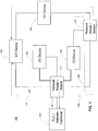
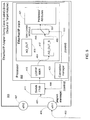
- FIG. 1 shows system 100 with a network controller 101 interacting with I/O devices 103-109 according to an embodiment of the invention.
- a network controller or in this embodiment programmable logic controller (PLC) 101, communicates with I/O device (adapter) 103 by sending duplicate messages over paths 151 and 153 in the forward direction.
- PLC programmable logic controller
- network controller 101 sends only one multicast message to switch 111. Consequently, switch 111 sends multicast messages to I/O device 103 over paths 151 and 153.
- a path may traverse network routers and switches (e.g., network router/switch 111 and 113) and/or other I/O devices (e.g., I/O device 109) with a daisy chain configuration.
- path 151 or path 153 fails (e.g., when a cable is mistakenly removed)
- transmission from network controller 101 to I/O device 103 can continue without establishing a new path after determining that path 151 has failed.
- I/O device 103 can transmit a message over path 155.
- failure mechanisms in the forward and reverse directions may be symmetric, embodiments of the inventions may support asymmetric failure modes.
- the failure mechanism is symmetric, if path 151 fails in the forward direction, then I/O device 103 can communicate to network controller 101 over path 155 in the reverse direction.
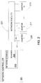
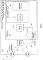
- FIG. 2 shows network controller 101 connected to adapters 209-213 over network facility 207 (e.g., the network of system 100 as shown in Figure 1 ) according to an embodiment of the invention.
- network facility 207 may assume different types of networks, including an Ethernet network, using a standard communications protocol, User Datagram Protocol (UDP).
- UDP User Datagram Protocol
- Network controller 101 includes scanner 203, which resides within network interface 205.
- Network interface 205 may be a communications card that fits into a backplane of network controller 101.
- EtherNet/IP network is used as the main example, any communication protocol that replies upon multicast or broadcast of data messages may be supported.
- Device scanner 203 communicates with adapters 209-213, both locally (located on the backplane of network controller 101) or remotely (over network facility 207).
- a device scan table may be provided for storing data relating to the adapters 209-213. (The device scan table may include parameters which can be used by scanner 203 to communicate with adapters 209-213.)
- a standard communications interface e.g., a UDP/IP stack with an Ethernet driver, may be provided for interfacing between the device scanner 203 and network facility 207 using a standard communication protocol, e.g., UDP.
- network facility 207 typically provides a fast, flexible, and convenient way of interconnecting I/O devices 209-213 and may support interconnection with a plurality of network controllers (not shown).
- Network controller 101 typically comprises a microprocessor and memory (e.g., random access memory (RAM)), with software or firmware running therein.
- Network controller 101 may store a configuration table containing parameters associated with the scan table.
- the parameters within the configuration table may be read into the scan table upon start-up of network interface 205 and/or device scanner 203.
- embodiments of the present invention may have the parameters read into the scan table by other means, e.g., through a web page (accessible through the world wide web (WWW)) located on network interface 205.
- WWW world wide web
- the parameters may be placed into the scan table through a user creating/editing a file on the user's personal computer.
- network interface 205 may send the file to network interface 205 using a File Transfer Protocol (FTP) or some other transfer means from a remote location.
- FTP File Transfer Protocol
- network interface 205 also has a real time operating system for running the various tasks on the network interface 205, including an IO scan task.
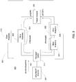
- FIG. 3 shows scanner 301 communicating with target adapter 303 over two transmission media 353 and 355 according to an embodiment of the invention.
- the exemplary embodiment utilizes EtherNet/IPTM (Ethernet Industrial Protocol), although embodiments of the invention can support other protocols.
- EtherNet/IP is an open industrial application layer protocol for industrial automation applications. It is supported by Open DeviceNet Vendors Association (ODVA).
- ODVA Open DeviceNet Vendors Association
- EtherNet/IP utilizes Ethernet hardware and software to define an application layer protocol for configuring, accessing, and controlling industrial automation devices.
- network 300 and the devices within network 300 support cable redundancy.
- Network 300 supports cable redundancy, including a daisy-chain loop in EtherNet/IP networks and devices.
- a daisy-chain loop architecture with a Modbus/TCP or Modbus/UDP network may be supported by embodiments of the invention.
- Modbus is a serial communications protocol for use with programmable logic controllers. Modbus allows for communication between many devices connected to the same network, for example, a system that measures temperature and humidity and communicates the results to a computer. Modbus is typically used to connect a supervisory computer with a remote terminal unit in supervisory control and data acquisition The Modbus protocol supports both serial ports and Ethernet ports.
- a common mode of failure in a distributed control network is a network cable disconnect.
- Cable redundancy refers to the network architecture, in which there are multiple routes from the controller device, e.g. a programmable logic controller (and its network scanner) to the slave device, e.g., an adapter, whereby the slave device has two or more physical cable connections to the network (and ultimately the controller device).
- a controller device e.g. a programmable logic controller (and its network scanner)
- the slave device e.g., an adapter
- Such an architecture is designed to allow one or more cables to be accidentally or intentionally disconnected while maintaining undisrupted communication between the devices.
- An EtherNet/IP device (e.g., target adapter 303) configures two or more physical Ethernet ports in order to utilize the redundant cable architecture of network 300.
- target adapter may comprise an adapter-class device, e.g., AdvantysTM EtherNet/IP network interface modules with two Ethernet ports, eth0 and eth1 having its own IP address, IP0 and IP1, respectively.
- embodiments of the invention can support more than two Ethernet ports (each port associated with a transmission medium) in order to obtain greater robustness against cable loss as well as failures in intermediate switches and other network devices.
- the two Ethernet ports inside target adapter 303 may be connected via managed switch 311. Since multicast packets are broadcast on Ethernet over communications media 353 and 355, managed switch 311 transmits a packet (multicast message) received via one port to the other port when managed switch 311 receives multicast packet 351 from scanner 301. For greater flexibility and performance, managed switch 311 may utilize Internet Group Management Protocol (IGMP) snooping.
- IGMP Internet Group Management Protocol
- the two Ethernet ports inside target adapter 303 may be connected via managed switch 311. If the switch 311 supports IGMP snooping, then when it receives a multicast packet 351 from scanner 301 destined for adapter 303, it will forward the packet via paths 353 and 355, but not via path 357.
- a switch may resort to flooding multicast packets to all ports (corresponding to other adapters 305-309 and 313, as shown in Figure 3 or I/O devices 105-109 as shown in Figure 1 ) within network 300.
- managed switch 311 intercepts (snoops) IGMP join and leave messages received on the interface from hosts. Traffic is forwarded only to those ports (e.g., eth0/IP0 and eth1/IP1 associated with target adapter 303) that have joined the multicast group, and not to 313. Traffic continues to be forwarded until the port (client) issues a leave message, at which time managed switch 311 stops forwarding traffic to the port. When all ports (nodes) have left the multicast group, managed switch 311 prunes off the traffic.
- VLAN's could be set up to minimize the unneeded (broadcast) packets in the loop.
- VLAN virtual LAN
- a group of network devices may be connected to different physical segments, but behaves as if they are on the same physical LAN. Such grouping allows switches to form different broadcast domains, thereby reducing the amount of broadcast packets.
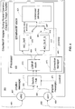
- Figure 4 shows adapter 303 during normal operation when receiving messages from scanner 301 according to an embodiment of the invention.
- Assembly objects (corresponding to data attributes that are stored in buffers) are used in an EtherNet/IP network to communicate input and output data that are transferred between the producer and the consumer.
- An assembly object may comprise basic information such as name and identification, file collection, and security specifications.
- a device may have multiple output assembly objects that correspond, for example, to discrete output and analog outputs.)
- buffer (AO OUT) 415 stores an assembly object for output data.
- buffer (AO_IN) 601 stores an assembly object for input data.
- embodiments of the invention may not utilize separate objects for input and output data.
- shadow buffer (AO_OUT_S) 417 stores a shadow assembly object that binds to the same data attributes for the regularly received assembly object (as stored in buffer 415) that binds to output data.
- AO_OUT 415 is populated with data received via port 407, while AO_OUT_S is populated with data received via port 409.
- EtherNet/IP scanner 301 sees adapter 303 at a particular IP address, IP0. Scanner 301 then establishes a class 1 connection (implicit messages) with adapter 303. For both forward and reverse directions (scanner to adapter and adapter to scanner), network 300 may use the multicast option.
- adapter 303 internally triggers second Ethernet port (ethl/IP1) 409 also to subscribe to the same multicast address subscribed by port (eth0/IP0) 407.
- managed switch 311 may provide the routing of multicast messages.
- the packet is delivered to both IP0 port 407 (over transmission medium 451) and IP1 port 409 (over transmission medium 453) by interfacing via the redundant routes/cables. If both transmission media 451 and 453 (coming into eth0 port 407 and eth1 port 409) are up and active, the implicit message arriving via eth0/IP0 port 407 is used to update AO_OUT buffer 415 (over path 455, switch 411, stack 413, and path 459).
- AO_OUT_S buffer 417 (over path 457, switch 411, stack 413, and path 461). Data in AO_OUT buffer 415 is used to update mapped attributes data structure 421 in the class, while data in AO_OUT_S buffer 417 is dormant.
- eth0/IP0 port 407 is the main/default (primary) port that updates attributes data structure 421 through switching module 419 over paths 463 and 467. Since it is not known a priori which port will be better, adapter 303 chooses one port as the primary.
- the primary port (port 407 as shown in Figure 4 ) remains the primary port unless/until adapter detects a disruption in network connection, e.g., cable disconnect.
- AO_OUT_S buffer 417 rather than AO_OUT buffer 415 is used to update the attributes data structure 421 mapped in the object.
- Connection manager 423 monitors the integrity of transmission media 451 and 453 and configures switch 411 and switching module 419 through control signals 471 and 469, respectively, so that attributes data structure 421 is updated from AO_OUT buffer 415 when transmission medium 451 is operational.
- connection manager 423 may consider the loss of messages (e.g., when a cable is disconnected) as well as message delays (which may result from delays in network switches and intermediate adapters). For example, if a multicast packet arrives as port 409 (eth1) substantially earlier than at port 407 (eth0), then connection manager 423 may select port 409 as the primary port.
- connection manager 423 configures switching module 419 and switch 411 with control signals 553 and 555, respectively, so that attributes data structure 421 is updated from AO_OUT_S buffer 417 through paths 465 and 551.
- processor 403 supports the functionalities of UDP/IP stack 413, connection manager 423, buffers 415 and 417, switching module 419, and attributes data structure 421.
- Processor 403 utilizes memory (not explicitly shown) that stores computer-executable instructions for processor 403 to execute in order to support the above functionalities.
- Figure 5 shows adapter 303 during abnormal operation when receiving messages from scanner 301 according to an embodiment of the invention. If there is a cable disconnect in the primary port 407(eth0), AO_OUT buffer 415 no longer is used to update attributes data structure 421 as mapped in the assembly object. Instead, adapter 303 uses AO_OUT_S buffer 417. As eth1 port 409 continues to receive the implicit messages from scanner 301, no messages will have been lost because the connection to port 409 was established before failure of transmission medium 451. As previously discussed, if greater robustness in desired, additional ports with additional transmission media may be supported.
- any multicast packets received via one Ethernet port may be sent out the other Ethernet port, depending on the capability and configuration of adapter 303. Consequently, embodiments of the invention may support a daisy chain configuration in which a message passes through an adapter (e.g., adapter 305 as shown in Figure 3 ) to target adapter 303. In such a case, if an adapter receives a multicast packet that is not directed to the adapter, the adapter sends (relays) the packet out via the other port.
- an adapter e.g., adapter 305 as shown in Figure 3
- embodiments of the invention may utilize a physical level detection scheme in which a loss of a physical signal is detected.
- the detection scheme may use some sort of timeout.
- EtherNet/IP the detection scheme may rely on the output data message itself, as the scanner 301 may periodically transmit new multicast packets to adapter 303. If no new packet is received at port 407 (eth0) (beyond when it was expected) but port 409 (eth1) has received a new packet, then connection manager 423 may decide that port 407is down and port 409 is up.
- adapter 303 monitors transmission medium 451 for a heartbeat signal from scanner 301 to determine if transmission medium 451 is operational.
- the heartbeat signal may comprise a periodically transmitted message from scanner 301. If adapter 303 does not receive a heartbeat signal within a predetermined time interval, adapter 303 deems that transmission medium 451 is non-operational. That being the case, if a heartbeat signal is detected at port 409, then adapter 303 uses AO_OUT_S buffer 417 to update attributes data structure 421.
- Figure 6 shows adapter 303 during normal operation when transmitting messages to scanner 301 according to an embodiment of the invention.
- the operation from adapter 303 to scanner 301 varies from the operation from scanner 301 to adapter 303 as previously discussed.
- Processor 403 stores an assembly object from attributes data structure 601 and then inserts the assembly object in AO_IN buffer 603.
- Processor 403 then formats a transmitted message from data attributes in attributes data structure 601.
- primary port 407 is used to transmit the formatted message to scanner 301 through switch 411, path 653, and primary transmission medium 655.
- Figure 7 shows adapter 303 during abnormal operation when transmitting messages to scanner 301 according to an embodiment of the invention. If adapter 303 detects a cable break in transmission medium 655 (corresponding to primary port 407), adapter 303 dynamically changes the IP address bound to eth1 port 409 to that used by eth0 port 407. Adapter 303 sends the message over secondary transmission medium 753 through path 751 and secondary port 409, as controlled by connection manager 423 through control signals 755 and 757. Adapter 303 continues to sends messages as before the transmission disruption. However, the operation of scanner 301 is transparent to the reconfiguration at adapter 303.
- adapter 303 For support both transmission to and from adapter 303, transfer to the redundant cable connection can be seamless, i.e., no packets are dropped. Also, features of adapter 303 are consistent with EtherNet/IP technology and specifications, preserving investment in scanner 301 and the network infrastructure (including transmission media and switches).
- symmetry of transmission integrity may be assumed with a standard-based network.
- adapter 303 deems that transmission from adapter 303 to scanner 301 has also failed for the same transmission medium. If that is the case, adapter 303 utilizes the other port to send messages to scanner 301.
- other embodiments of the invention may not assume symmetric transmission integrity, where different transmission media are used for the forward and reverse directions between scanner 301 and adapter 303 and where it is possible to independently detect the physical link state of each transmission medium. For example, the receive link of port 407 (eth0) may be good, while the transmit link of port 407 may be bad.
- the computer system may include at least one computer such as a microprocessor, digital signal processor, and associated peripheral electronic circuitry.
Landscapes
- Engineering & Computer Science (AREA)
- Computer Networks & Wireless Communication (AREA)
- Signal Processing (AREA)
- Small-Scale Networks (AREA)
- Data Exchanges In Wide-Area Networks (AREA)
Description
- Computer systems and network computing operations are increasingly relied upon by individuals, businesses and governments for critical services and business operations. In such systems, network uptime can be critical to the smooth operation of the underlying service or operation, and a network failure must be promptly isolated or restored. Thus, fault isolation and automatic recovery under network failure conditions are crucial requirements for higher bandwidth networks and task-critical networks. In addition, in a typical network failure and recovery scenario, delay on the order of even a few hundred milliseconds can be critical.
- In manufacturing or other automation systems, architectures may be decentralized or distributed while delivering performance comparable to centralized systems. For instance, the Advantys STB distributed I/O system is an open, modular input/output system that makes it possible to design islands of automation managed by a master controller via a bus or communication network. The Advantys STB distributed I/O system is a product of Schneider Automation Inc., One High Street, North Andover, Massachusetts. Another problem that can be encountered during a network failure scenario is the inability to access the physical links or devices at the location of the failure.
- Often, the island and associated I/O modules may be widely dispersed and may be in isolated locations, or the target systems may be enclosed in other machinery. In these types of network operations, getting physical access to a remote I/O module or network link during a failure situation can be difficult. Furthermore, in networks such as industrial automation systems, reliability is critical. In a factory, for instance, if a network connection goes down, operators could be physically harmed. In these types of network operations, fault recovery must be automatic.
- With the increased complexity of industrial automation applications, computer networks in an industrial setting often include numerous devices that are connected over a network such as an EtherNet/IP network. In order to ensure that the devices are able to communicate with each other in a reliable fashion, redundant cabling is often used to provide transmission media. If a transmission medium becomes non-operational (e.g., when a cable is inadvertently removed), a controller may typically require a substantial amount of time to detect the non-operational transmission medium in a real-time control network. Once detected, the controller can reconfigure the transmission path to utilize the redundant cabling. However, during reconfiguration of the transmission path, messages may be lost between devices on the network.
- In a typical fault recovery scenario, when a failure occurs, data traffic is rerouted or switched from a current faulty path to a backup path. Depending on the actual redundancy strategy, the standby or backup data path may be dedicated, may require a physical change in connections, or may be a virtual backup path to the active or primary path. Current software methods for providing redundancy in a network require that the devices on the network analyze or discover the entire network to determine a backup path. Rapid Spanning Tree Protocol (RSTP) and Hirschmann HIPER-Ring are two such methods. In both RSTP and Hirschmann HIPER-Ring, the entire network must be discovered before rerouting can be implemented, adding both time and the use of computing resources to fault recovery. In addition, in both RSTP and Hirschmann HIPER-Ring, the network devices implementing the fault recovery must communicate with other network devices on the network.
- Thus, there is a real market need to provide a reliable and expeditious approach for providing redundant transmission media in a real-time control network without appreciably disrupting operation.
- "Programmable Controller Networking - Dual Cable, Redundancy, Multiple Networks and Applications", Edmonds C., XP000328967, and United States Patent Application Publications
US-A-2005/091394 ,US-A-2003/179749 andUS-A-2006/050631 disclose networked systems and are concerned with network redundancy and providing 1+1 protections mechanisms. - Viewed from one aspect, the present invention provides an adapter comprising: a first port having a first Internet Protocol address and configured to join a multicast group so as to receive a first received multicast message of said multicast group over a first transmission route, wherein the first received multicast message contains output data; a second port having a second Internet Protocol address and configured to join said multicast group so as to receive a second received multicast message of said multicast group over a second transmission route, wherein the second received multicast message contains the output data; a switching module coupled to the first port and the second port; a memory module containing a data structure; and a connection manager configured to: determine whether the first transmission route and the second transmission route are operational; instruct the switching module to direct the output data contained in the first received multicast message to the data structure when the first transmission route is operational; instruct the switching module to direct the output data contained in the second received multicast message to the data structure when the first transmission route is non-operational and when the second transmission route is operational; and dynamically change the Internet Protocol address of the second port to the Internet Protocol address of the first port when the first transmission route is non-operational and the second transmission route is operational.
- Viewed from another aspect, the present invention provides a method comprising: subscribing a first port of a device to a multicast address, the first port having a first Internet Protocol address; subscribing a second port of the device to said multicast address, the second port having a second Internet Protocol address; receiving a first received multicast message at the first port over a first transmission route, wherein the first received multicast message contains output data; receiving a second received multicast message at the second port over a second transmission route, wherein the second received multicast message contains the output data; wherein the first and second received multicast messages are part of a same multicast group; determining whether the first transmission route and the second transmission route are operational; directing the output data contained in the first received multicast message to the data structure when the first transmission route is operational; directing the output data contained in the second received multicast message to the data structure when the first transmission route is non-operational and when the second transmission route is operational; and dynamically changing the Internet Protocol address of the second port to the Internet Protocol address of the first port when the first transmission route is non-operational and the second transmission route is operational.
- An invention relates to apparatuses and methods for supporting cable redundancy in a network connecting a network controller and an I/O device. The network typically includes a switch and supports a plurality of adapters, in which two or more transmission media are configured between a scanner and each of the adapters. Additionally, switches and routers may be situated between the scanner and the adapter.
- The adapter includes a first port and a second port for receiving first and second messages from a scanner over a first and second transmission media, respectively, where both messages contain the same output data. A connection module instructs a switching module to direct the output data contained in the first message to a data structure when the first transmission medium is operational. When the first transmission medium is non-operational and the second transmission medium is operational, the connection manager instructs the switching module to direct the output data contained in the second message to the data structure. The adapter dynamically changes an assigned address of the second port to an address of a first port when a first transmission medium is non-operational and a second transmission medium is operational. Consequently, the communicating partner does not detect the communication error that may necessitate the communication partner to operate differently from normal operation.
- In a preferred embodiment, the adapter formats a message from input data. In this preferred embodiment a connection manager instructs the switch to direct the message to a primary port when a primary transmission medium is operational and instructs the switch to direct the message to a secondary port when the primary transmission medium is non-operational and the secondary transmission medium is operational.
- According to the invention, the adapter subscribes to a multicast address so that a message received at a second port is the same as a message received at a first port during normal operation. Consequently, output data arrives to the adapter via multicast addressing.
- A more complete understanding of the present invention and the advantages thereof may be acquired by referring to the following description in consideration of the accompanying drawings, in which like reference numbers indicate like features and wherein:
-
Figure 1 shows a system with a network controller interacting with I/O devices according to an embodiment of the invention. -
Figure 2 shows a network controller connected to adapters over a network facility according to an embodiment of the invention. -
Figure 3 shows a scanner communicating with a target adapter over two transmission media according to an embodiment of the invention. -
Figure 4 shows an adapter during normal operation when receiving messages from a scanner according to an embodiment of the invention. -
Figure 5 shows an adapter during abnormal operation (in which a transmission medium fails) when receiving messages from a scanner according to an embodiment of the invention. -
Figure 6 shows an adapter during normal operation when transmitting messages to a scanner according to an embodiment of the invention. -
Figure 7 shows an adapter during abnormal operation when transmitting messages to a scanner according to an embodiment of the invention. - In the following description of the various embodiments, reference is made to the accompanying drawings which form a part hereof, and in which is shown by way of illustration various embodiments in which the invention may be practiced. It is to be understood that other embodiments may be utilized and structural and functional modifications may be made without departing from the scope of the present invention.
- The following clarify terms pertaining to the discussion herein.
- ➢ Scanner: A type of network device that can respond to connection requests and that can initiate connections. With a master-slave relationship, a scanner is categorized as a master device. With an EtherNet/IP network, a scanner is associated with a scanner class device during a connection establishment phase and typically connects directly to a controller.
- ➢ Adapter: A type of network device that communicates with a scanner but does not initiate connections. With a master-slave relationship, an adapter is categorized as a slave device during a connection establishment phase. Examples of an adapter include an I/O device and a variable speed device. With an EtherNet/IP network, an adapter is associated with an adapter class device.
-
Figure 1 showssystem 100 with anetwork controller 101 interacting with I/O devices 103-109 according to an embodiment of the invention. As an example, a network controller, or in this embodiment programmable logic controller (PLC) 101, communicates with I/O device (adapter) 103 by sending duplicate messages overpaths network controller 101 sends only one multicast message to switch 111. Consequently,switch 111 sends multicast messages to I/O device 103 overpaths switch 111 and 113) and/or other I/O devices (e.g., I/O device 109) with a daisy chain configuration. (In the example shown inFigure 1 , two paths may be configured fromnetwork controller 101 to each I/O device 103-109.) As will be discussed in greater detail, if eitherpath 151 orpath 153 fails (e.g., when a cable is mistakenly removed), transmission fromnetwork controller 101 to I/O device 103 can continue without establishing a new path after determining thatpath 151 has failed. - In the reverse direction (i.e., from I/
O device 103 to network controller 101), I/O device 103 can transmit a message overpath 155. (While failure mechanisms in the forward and reverse directions may be symmetric, embodiments of the inventions may support asymmetric failure modes.) When the failure mechanism is symmetric, ifpath 151 fails in the forward direction, then I/O device 103 can communicate to networkcontroller 101 overpath 155 in the reverse direction. -
Figure 2 showsnetwork controller 101 connected to adapters 209-213 over network facility 207 (e.g., the network ofsystem 100 as shown inFigure 1 ) according to an embodiment of the invention. With embodiments of the invention,network facility 207 may assume different types of networks, including an Ethernet network, using a standard communications protocol, User Datagram Protocol (UDP).Network controller 101 includesscanner 203, which resides withinnetwork interface 205.Network interface 205 may be a communications card that fits into a backplane ofnetwork controller 101. Even though EtherNet/IP network is used as the main example, any communication protocol that replies upon multicast or broadcast of data messages may be supported. -
Device scanner 203 communicates with adapters 209-213, both locally (located on the backplane of network controller 101) or remotely (over network facility 207). A device scan table may be provided for storing data relating to the adapters 209-213. (The device scan table may include parameters which can be used byscanner 203 to communicate with adapters 209-213.) A standard communications interface, e.g., a UDP/IP stack with an Ethernet driver, may be provided for interfacing between thedevice scanner 203 andnetwork facility 207 using a standard communication protocol, e.g., UDP. With an Ethernet implementation,network facility 207 typically provides a fast, flexible, and convenient way of interconnecting I/O devices 209-213 and may support interconnection with a plurality of network controllers (not shown). -
Network controller 101 typically comprises a microprocessor and memory (e.g., random access memory (RAM)), with software or firmware running therein.Network controller 101 may store a configuration table containing parameters associated with the scan table. The parameters within the configuration table may be read into the scan table upon start-up ofnetwork interface 205 and/ordevice scanner 203. However, embodiments of the present invention may have the parameters read into the scan table by other means, e.g., through a web page (accessible through the world wide web (WWW)) located onnetwork interface 205. Alternatively, the parameters may be placed into the scan table through a user creating/editing a file on the user's personal computer. The user may send the file tonetwork interface 205 using a File Transfer Protocol (FTP) or some other transfer means from a remote location. With embodiments of the invention,network interface 205 also has a real time operating system for running the various tasks on thenetwork interface 205, including an IO scan task. -
Figure 3 showsscanner 301 communicating withtarget adapter 303 over twotransmission media - As shown in
Figure 3 ,network 300 and the devices withinnetwork 300 support cable redundancy.Network 300 supports cable redundancy, including a daisy-chain loop in EtherNet/IP networks and devices. Also, a daisy-chain loop architecture with a Modbus/TCP or Modbus/UDP network may be supported by embodiments of the invention. Modbus is a serial communications protocol for use with programmable logic controllers. Modbus allows for communication between many devices connected to the same network, for example, a system that measures temperature and humidity and communicates the results to a computer. Modbus is typically used to connect a supervisory computer with a remote terminal unit in supervisory control and data acquisition The Modbus protocol supports both serial ports and Ethernet ports. - With embodiments of the invention, changes are implemented only in the individual slave devices (e.g., adapters 303-309) without changes in the master devices (e.g., scanner 301) that are already deployed with prior art technology. A common mode of failure in a distributed control network is a network cable disconnect. Cable redundancy refers to the network architecture, in which there are multiple routes from the controller device, e.g. a programmable logic controller (and its network scanner) to the slave device, e.g., an adapter, whereby the slave device has two or more physical cable connections to the network (and ultimately the controller device). Such an architecture is designed to allow one or more cables to be accidentally or intentionally disconnected while maintaining undisrupted communication between the devices.
- An EtherNet/IP device (e.g., target adapter 303) configures two or more physical Ethernet ports in order to utilize the redundant cable architecture of
network 300. For example, target adapter may comprise an adapter-class device, e.g., Advantys™ EtherNet/IP network interface modules with two Ethernet ports, eth0 and eth1 having its own IP address, IP0 and IP1, respectively. However, embodiments of the invention can support more than two Ethernet ports (each port associated with a transmission medium) in order to obtain greater robustness against cable loss as well as failures in intermediate switches and other network devices. - The two Ethernet ports inside
target adapter 303 may be connected via managedswitch 311. Since multicast packets are broadcast on Ethernet overcommunications media switch 311 transmits a packet (multicast message) received via one port to the other port when managedswitch 311 receivesmulticast packet 351 fromscanner 301. For greater flexibility and performance, managedswitch 311 may utilize Internet Group Management Protocol (IGMP) snooping. - The two Ethernet ports inside
target adapter 303 may be connected via managedswitch 311. If theswitch 311 supports IGMP snooping, then when it receives amulticast packet 351 fromscanner 301 destined foradapter 303, it will forward the packet viapaths path 357. - Without IGMP snooping, a switch (at layer 2) may resort to flooding multicast packets to all ports (corresponding to other adapters 305-309 and 313, as shown in
Figure 3 or I/O devices 105-109 as shown inFigure 1 ) withinnetwork 300. However, with embodiments of the invention, managedswitch 311 intercepts (snoops) IGMP join and leave messages received on the interface from hosts. Traffic is forwarded only to those ports (e.g., eth0/IP0 and eth1/IP1 associated with target adapter 303) that have joined the multicast group, and not to 313. Traffic continues to be forwarded until the port (client) issues a leave message, at which time managedswitch 311 stops forwarding traffic to the port. When all ports (nodes) have left the multicast group, managedswitch 311 prunes off the traffic. - Alternatively, VLAN's could be set up to minimize the unneeded (broadcast) packets in the loop. In a virtual LAN (VLAN), a group of network devices may be connected to different physical segments, but behaves as if they are on the same physical LAN. Such grouping allows switches to form different broadcast domains, thereby reducing the amount of broadcast packets.
-
Figure 4 showsadapter 303 during normal operation when receiving messages fromscanner 301 according to an embodiment of the invention. Assembly objects (corresponding to data attributes that are stored in buffers) are used in an EtherNet/IP network to communicate input and output data that are transferred between the producer and the consumer. (An assembly object may comprise basic information such as name and identification, file collection, and security specifications. A device may have multiple output assembly objects that correspond, for example, to discrete output and analog outputs.) As shown inFigure 3 , buffer (AO OUT) 415 stores an assembly object for output data. As shown inFigure 6 , buffer (AO_IN) 601 stores an assembly object for input data. However, embodiments of the invention may not utilize separate objects for input and output data. - In order to provide redundancy, shadow buffer (AO_OUT_S) 417 stores a shadow assembly object that binds to the same data attributes for the regularly received assembly object (as stored in buffer 415) that binds to output data.
AO_OUT 415 is populated with data received viaport 407, while AO_OUT_S is populated with data received viaport 409. - During network/device configuration, EtherNet/
IP scanner 301 seesadapter 303 at a particular IP address, IP0.Scanner 301 then establishes aclass 1 connection (implicit messages) withadapter 303. For both forward and reverse directions (scanner to adapter and adapter to scanner),network 300 may use the multicast option. When aclass 1 connection is established betweenscanner 301 and adapter 303 (where port eth0/IP0 407 ofadapter 303 subscribes to the multicast address agreed upon during the connection establishment phase),adapter 303 internally triggers second Ethernet port (ethl/IP1) 409 also to subscribe to the same multicast address subscribed by port (eth0/IP0) 407. As described above, managedswitch 311 may provide the routing of multicast messages. - After completing the configuration described above, whenever
scanner 301 multicasts an implicit message to the adapter, the packet is delivered to both IP0 port 407 (over transmission medium 451) and IP1 port 409 (over transmission medium 453) by interfacing via the redundant routes/cables. If bothtransmission media 451 and 453 (coming intoeth0 port 407 and eth1 port 409) are up and active, the implicit message arriving via eth0/IP0 port 407 is used to update AO_OUT buffer 415 (overpath 455,switch 411,stack 413, and path 459). (Proper operation of a transmission medium requires the integrity of the associated cables as well as network devices along the routes.) The same implicit message arriving via eth1/IP1 port 409 is used to update AO_OUT_S buffer 417 (overpath 457,switch 411,stack 413, and path 461). Data inAO_OUT buffer 415 is used to update mappedattributes data structure 421 in the class, while data inAO_OUT_S buffer 417 is dormant. - In the example shown in
Figure 4 , one assumes that eth0/IP0 port 407 is the main/default (primary) port that updates attributesdata structure 421 through switchingmodule 419 overpaths adapter 303 chooses one port as the primary. The primary port (port 407 as shown inFigure 4 ) remains the primary port unless/until adapter detects a disruption in network connection, e.g., cable disconnect. As will be discussed inFigure 5 , if there is a cable disconnect or other network failure in the primary port 407(eth0),AO_OUT_S buffer 417 rather thanAO_OUT buffer 415 is used to update theattributes data structure 421 mapped in the object. -
Connection manager 423 monitors the integrity oftransmission media switch 411 and switchingmodule 419 throughcontrol signals data structure 421 is updated fromAO_OUT buffer 415 whentransmission medium 451 is operational. When determining if a transmission route is operational,connection manager 423 may consider the loss of messages (e.g., when a cable is disconnected) as well as message delays (which may result from delays in network switches and intermediate adapters). For example, if a multicast packet arrives as port 409 (eth1) substantially earlier than at port 407 (eth0), thenconnection manager 423 may selectport 409 as the primary port. As will be discussed withFigure 5 ,connection manager 423 configures switchingmodule 419 and switch 411 withcontrol signals data structure 421 is updated fromAO_OUT_S buffer 417 throughpaths - With the embodiment shown in
Figure 4 ,processor 403 supports the functionalities of UDP/IP stack 413,connection manager 423,buffers module 419, and attributesdata structure 421.Processor 403 utilizes memory (not explicitly shown) that stores computer-executable instructions forprocessor 403 to execute in order to support the above functionalities. -
Figure 5 showsadapter 303 during abnormal operation when receiving messages fromscanner 301 according to an embodiment of the invention. If there is a cable disconnect in the primary port 407(eth0),AO_OUT buffer 415 no longer is used to updateattributes data structure 421 as mapped in the assembly object. Instead,adapter 303 usesAO_OUT_S buffer 417. As eth1port 409 continues to receive the implicit messages fromscanner 301, no messages will have been lost because the connection to port 409 was established before failure oftransmission medium 451. As previously discussed, if greater robustness in desired, additional ports with additional transmission media may be supported. - Note that any multicast packets received via one Ethernet port may be sent out the other Ethernet port, depending on the capability and configuration of
adapter 303. Consequently, embodiments of the invention may support a daisy chain configuration in which a message passes through an adapter (e.g.,adapter 305 as shown inFigure 3 ) to targetadapter 303. In such a case, if an adapter receives a multicast packet that is not directed to the adapter, the adapter sends (relays) the packet out via the other port. - In order to determine if a transmission medium is operational, embodiments of the invention may utilize a physical level detection scheme in which a loss of a physical signal is detected. To determine if there is a problem in a route (e.g., one of the switches in the route between
scanner 301 andadapter 303 is down), the detection scheme may use some sort of timeout. With EtherNet/IP, the detection scheme may rely on the output data message itself, as thescanner 301 may periodically transmit new multicast packets toadapter 303. If no new packet is received at port 407 (eth0) (beyond when it was expected) but port 409 (eth1) has received a new packet, thenconnection manager 423 may decide that port 407is down andport 409 is up. As another example,adapter 303monitors transmission medium 451 for a heartbeat signal fromscanner 301 to determine iftransmission medium 451 is operational. The heartbeat signal may comprise a periodically transmitted message fromscanner 301. Ifadapter 303 does not receive a heartbeat signal within a predetermined time interval,adapter 303 deems thattransmission medium 451 is non-operational. That being the case, if a heartbeat signal is detected atport 409, thenadapter 303 usesAO_OUT_S buffer 417 to updateattributes data structure 421. -
Figure 6 showsadapter 303 during normal operation when transmitting messages toscanner 301 according to an embodiment of the invention. The operation fromadapter 303 toscanner 301 varies from the operation fromscanner 301 toadapter 303 as previously discussed.Processor 403 stores an assembly object fromattributes data structure 601 and then inserts the assembly object inAO_IN buffer 603.Processor 403 then formats a transmitted message from data attributes inattributes data structure 601. During normal operation, as controlled by connection manager throughcontrol signals primary port 407 is used to transmit the formatted message toscanner 301 throughswitch 411,path 653, andprimary transmission medium 655. -
Figure 7 showsadapter 303 during abnormal operation when transmitting messages toscanner 301 according to an embodiment of the invention. Ifadapter 303 detects a cable break in transmission medium 655 (corresponding to primary port 407),adapter 303 dynamically changes the IP address bound to eth1port 409 to that used by eth0port 407.Adapter 303 sends the message oversecondary transmission medium 753 throughpath 751 andsecondary port 409, as controlled byconnection manager 423 throughcontrol signals Adapter 303 continues to sends messages as before the transmission disruption. However, the operation ofscanner 301 is transparent to the reconfiguration atadapter 303. - For support both transmission to and from
adapter 303, transfer to the redundant cable connection can be seamless, i.e., no packets are dropped. Also, features ofadapter 303 are consistent with EtherNet/IP technology and specifications, preserving investment inscanner 301 and the network infrastructure (including transmission media and switches). - With embodiments of the invention, symmetry of transmission integrity may be assumed with a standard-based network. In other words, if a transmission failure is detected from
scanner 301 toadapter 303,adapter 303 deems that transmission fromadapter 303 toscanner 301 has also failed for the same transmission medium. If that is the case,adapter 303 utilizes the other port to send messages toscanner 301. However, other embodiments of the invention may not assume symmetric transmission integrity, where different transmission media are used for the forward and reverse directions betweenscanner 301 andadapter 303 and where it is possible to independently detect the physical link state of each transmission medium. For example, the receive link of port 407 (eth0) may be good, while the transmit link ofport 407 may be bad. - As can be appreciated by one skilled in the art, a computer system with an associated computer-readable medium containing instructions for controlling the computer system can be utilized to implement the exemplary embodiments that are disclosed herein. The computer system may include at least one computer such as a microprocessor, digital signal processor, and associated peripheral electronic circuitry.
- While the invention has been described with respect to specific examples including presently preferred modes of carrying out the invention, those skilled in the art will appreciate that there are numerous variations and permutations of the above described systems and techniques that fall within the scope of the invention as set forth in the appended claims.
Claims (13)
- An adapter (303) comprising:a first port (407) having a first Internet Protocol address and configured to join a multicast group so as to receive a first received multicast message of said multicast group over a first transmission route (451), wherein the first received multicast message contains output data;a second port (409) having a second Internet Protocol address and configured to join said multicast group so as to receive a second received multicast message of said multicast group over a second transmission route (453), wherein the second received multicast message contains the output data;a switching module (419) coupled to the first port and the second port;a memory module containing a data structure (421); anda connection manager (423) configured to:wherein the connection manager is further configured to:determine whether the first transmission route and the second transmission route are operational;instruct the switching module to direct the output data contained in the first received multicast message to the data structure when the first transmission route is operational; andinstruct the switching module to direct the output data contained in the second received multicast message to the data structure when the first transmission route is non-operational and when the second transmission route is operational,dynamically change the Internet Protocol address of the second port to the Internet Protocol address of the first port when the first transmission route is non-operational and the second transmission route is operational.
- The adapter of claim 1, wherein the adapter comprises an I/O device (103).
- The adapter of claims 1 or 2, wherein the adapter supports an EtherNet/IP protocol.
- The adapter of any of claims 1-3, wherein the adapter is configured to format a transmitted message from input data, the adapter further comprising:a switch (411);the connection manager further configured to:instruct the switch to direct the transmitted message to the first port having the first IP address when the first transmission route is operational; andinstruct the switch to direct the transmitted message to the second port having the second IP address when the first transmission route is non-operational and when the second transmission route is operational.
- The adapter of claim 4, further comprising:a first output buffer (415) configured to convey the first received multicast message from the switch to the switching module.
- The adapter of claim 5, further comprising:a second output buffer (417) configured to convey the second received multicast message from the switch to the switching module.
- The adapter of claim 6, wherein the second output buffer binds to a same data attribute as the first output buffer.
- The adapter of claim 4, further comprising:an input buffer (603) configured to convey the transmitted message to the switch.
- The adapter of any of claims 1 to 8, wherein the adapter is part of an industrial automation system.
- The adapter of any of claims 1 to 9, wherein the connection manager is further configured to determine whether the first transmission route is non-operational and the second transmission route is operational based on a comparison of a message delay of the first and second transmission routes.
- A method comprising:subscribing a first port of a device to a multicast address, the first port having a first Internet Protocol address;subscribing a second port of the device to said multicast address, the second port having a second Internet Protocol address;receiving a first received multicast message at the first port over a first transmission route, wherein the first received multicast message contains output data;receiving a second received multicast message at the second port over a second transmission route, wherein the second received multicast message contains the output data;wherein the first and second received multicast messages are part of a same multicast group,determining whether the first transmission route and the second transmission route are operational;directing the output data contained in the first received multicast message to a data structure when the first transmission route is operational; anddirecting the output data contained in the second received multicast message to the data structure when the first transmission route is non-operational and when the second transmission route is operational;wherein the method further includes dynamically changing the Internet Protocol address of the second port to the Internet Protocol address of the first port when the first transmission route is non-operational and the second transmission route is operational.
- The method of claim 11, further comprising:formatting a transmitted message from input data;directing the transmitted message to the first port having the first IP address when the first transmission route is operational; anddirecting the transmitted message to the second port having the second IP address when the first transmission route is non-operational and when the second transmission route is operational.
- The method of claims 11 or 12, further comprising determining whether the first transmission route is non-operational and the second transmission route is operational based on a comparison of a message delay of the first and second transmission routes.
Applications Claiming Priority (2)
| Application Number | Priority Date | Filing Date | Title |
|---|---|---|---|
| US11/966,196 US8230115B2 (en) | 2007-12-28 | 2007-12-28 | Cable redundancy with a networked system |
| PCT/US2008/088184 WO2009086389A1 (en) | 2007-12-28 | 2008-12-23 | Cable redundancy with a networked system |
Publications (2)
| Publication Number | Publication Date |
|---|---|
| EP2250737A1 EP2250737A1 (en) | 2010-11-17 |
| EP2250737B1 true EP2250737B1 (en) | 2016-11-23 |
Family
ID=40343809
Family Applications (1)
| Application Number | Title | Priority Date | Filing Date |
|---|---|---|---|
| EP08869019.3A Not-in-force EP2250737B1 (en) | 2007-12-28 | 2008-12-23 | Cable redundancy with a networked system |
Country Status (8)
| Country | Link |
|---|---|
| US (1) | US8230115B2 (en) |
| EP (1) | EP2250737B1 (en) |
| CN (1) | CN101965691B (en) |
| AU (1) | AU2008345124B2 (en) |
| BR (1) | BRPI0821430A2 (en) |
| CA (1) | CA2710855C (en) |
| MX (1) | MX2010007161A (en) |
| WO (1) | WO2009086389A1 (en) |
Families Citing this family (12)
| Publication number | Priority date | Publication date | Assignee | Title |
|---|---|---|---|---|
| US8947228B2 (en) * | 2012-04-05 | 2015-02-03 | Schneider Electric Industries Sas | Diagnostics of hot-standby/redundant owner system in an EtherNet/IP adapter device |
| EP2784988B1 (en) | 2013-03-27 | 2015-12-09 | Siemens Aktiengesellschaft | Communication interface module for a modular control device of an industrial automation system |
| US8824299B1 (en) | 2014-02-28 | 2014-09-02 | tw telecom holdings, inc. | Selecting network services based on hostname |
| CN104104487A (en) * | 2014-07-23 | 2014-10-15 | 河北远东通信系统工程有限公司 | Duplicated hot-redundancy double-network system and network switching method |
| US10340057B2 (en) * | 2015-11-24 | 2019-07-02 | Cisco Technology, Inc. | Unified power and data cable |
| US9716348B2 (en) | 2015-12-18 | 2017-07-25 | Cisco Technology, Inc. | Connector for a unified power and data cable |
| CN111478778B (en) * | 2020-04-03 | 2021-11-02 | 中电科航空电子有限公司 | Method for reducing RSTP looped network power consumption and application thereof |
| CN112260893B (en) * | 2020-10-14 | 2022-04-19 | 天津津航计算技术研究所 | Ethernet redundancy device of VxWorks operating system based on network heartbeat |
| CN113111029B (en) * | 2021-04-14 | 2024-03-26 | 广州希姆半导体科技有限公司 | Method, chip and storage medium for determining data transmission path |
| US11638326B1 (en) * | 2021-12-14 | 2023-04-25 | Dish Wireless L.L.C. | Systems and methods for radio unit backup connections |
| CN114726673B (en) * | 2022-03-22 | 2023-10-31 | 深圳渊联技术有限公司 | Modbus TCP protocol communication method and communication system |
| TWI892162B (en) * | 2023-06-20 | 2025-08-01 | 四零四科技股份有限公司 | Network switch and link recovery method for dual-homing thereof |
Citations (1)
| Publication number | Priority date | Publication date | Assignee | Title |
|---|---|---|---|---|
| US6557112B1 (en) * | 1998-12-09 | 2003-04-29 | Nec Corporation | QOS protection system |
Family Cites Families (12)
| Publication number | Priority date | Publication date | Assignee | Title |
|---|---|---|---|---|
| US6016523A (en) * | 1998-03-09 | 2000-01-18 | Schneider Automation, Inc. | I/O modular terminal having a plurality of data registers and an identification register and providing for interfacing between field devices and a field master |
| FR2786891B1 (en) * | 1998-12-04 | 2001-01-12 | Schneider Automation | REDUNDANT AUTOMATION SYSTEM |
| US6327511B1 (en) * | 1998-12-30 | 2001-12-04 | Schneider Automation, Inc. | Input/output (I/O) scanner for a control system with peer determination |
| US6895024B1 (en) * | 1999-10-12 | 2005-05-17 | Marconi Communications, Inc. | Efficient implementation of 1+1 port redundancy through the use of ATM multicast |
| US6973024B1 (en) * | 2001-02-28 | 2005-12-06 | Utstarcom, Inc. | Method for modem element switchover using multicast groups |
| US20030016654A1 (en) * | 2001-06-14 | 2003-01-23 | Jayanta Das | Network and access protection in optical networks |
| US7251214B2 (en) * | 2002-03-21 | 2007-07-31 | Tropic Networks Inc. | System and method for providing protection of data communications in packet-based networks |
| FR2851387B1 (en) * | 2003-02-18 | 2005-04-08 | Thales Sa | NETWORK ARCHITECTURE ETHERNET / IP WITH HIGH SERVICE AVAILABILITY |
| CN1529472A (en) * | 2003-10-13 | 2004-09-15 | 中国科学院计算技术研究所 | High Performance Cluster Interconnect Network Adapter |
| US20050091394A1 (en) * | 2003-10-27 | 2005-04-28 | Schneider Automation Inc. | Software configurable dual cable redundant Ethernet or bus configuration |
| US7450494B2 (en) * | 2004-09-03 | 2008-11-11 | Cisco Technology, Inc. | Reconfigurable apparatus providing 1:N and 1:1 equipment redundancy for high speed broadband interfaces with 1+1 and 1:N automatic protection switching |
| ES2398482T3 (en) | 2006-05-30 | 2013-03-19 | Schneider Electric USA, Inc. | Remote configuration of virtual placeholder for distributed input / output modules |
-
2007
- 2007-12-28 US US11/966,196 patent/US8230115B2/en active Active
-
2008
- 2008-12-23 EP EP08869019.3A patent/EP2250737B1/en not_active Not-in-force
- 2008-12-23 WO PCT/US2008/088184 patent/WO2009086389A1/en not_active Ceased
- 2008-12-23 MX MX2010007161A patent/MX2010007161A/en active IP Right Grant
- 2008-12-23 CN CN200880127662.8A patent/CN101965691B/en not_active Expired - Fee Related
- 2008-12-23 BR BRPI0821430-1A patent/BRPI0821430A2/en not_active Application Discontinuation
- 2008-12-23 AU AU2008345124A patent/AU2008345124B2/en not_active Ceased
- 2008-12-23 CA CA2710855A patent/CA2710855C/en active Active
Patent Citations (1)
| Publication number | Priority date | Publication date | Assignee | Title |
|---|---|---|---|---|
| US6557112B1 (en) * | 1998-12-09 | 2003-04-29 | Nec Corporation | QOS protection system |
Also Published As
| Publication number | Publication date |
|---|---|
| US20090172193A1 (en) | 2009-07-02 |
| CN101965691B (en) | 2014-03-12 |
| AU2008345124B2 (en) | 2014-05-08 |
| EP2250737A1 (en) | 2010-11-17 |
| MX2010007161A (en) | 2010-09-30 |
| CA2710855C (en) | 2015-12-22 |
| WO2009086389A1 (en) | 2009-07-09 |
| CN101965691A (en) | 2011-02-02 |
| CA2710855A1 (en) | 2009-07-09 |
| US8230115B2 (en) | 2012-07-24 |
| BRPI0821430A2 (en) | 2015-06-16 |
| AU2008345124A1 (en) | 2009-07-09 |
Similar Documents
| Publication | Publication Date | Title |
|---|---|---|
| EP2250737B1 (en) | Cable redundancy with a networked system | |
| US7380154B2 (en) | Method and apparatus for network fault correction via adaptive fault router | |
| US8166187B2 (en) | Distributed IP gateway based on sharing a MAC address and IP address concurrently between a first network switching device and a second network switching device | |
| US8300523B2 (en) | Multi-chasis ethernet link aggregation | |
| CN103581164B (en) | For can carry out in the industrial communication network of redundant operation the method for message transmission and for can redundant operation industrial communication network communication equipment | |
| EP1895724B1 (en) | A method for implementing active/standby gateway device in the network and a system thereof | |
| EP3484074B1 (en) | Data center optical transport failure protection | |
| US9385944B2 (en) | Communication system, path switching method and communication device | |
| CN101971575B (en) | Method and apparatus for transparent auto-recovery in chain and ring networks | |
| EP1006702A2 (en) | Method and apparatus providing for an improved VRRP (Virtual Router Redundancy Protocol) | |
| WO2016097459A1 (en) | Redundancy in process control system | |
| CN101060533B (en) | A method, system and device for improving reliability of VGMP protocol | |
| US20230188874A1 (en) | Rapid Network Redundancy Failover | |
| CN113259235B (en) | IPv 6-based dual-active route redundancy method and system | |
| JP2007088949A (en) | Information processing apparatus, communication load distribution method, and communication load distribution program | |
| WO2006114809A1 (en) | Transmitting apparatus, and method for redundancy between transmitting apparatus and layer 2 switch | |
| CN111130964B (en) | Control cluster and method for operating a control cluster | |
| US20120063299A1 (en) | Highly available virtual packet network device | |
| CN101291258B (en) | Ethernet loop processing method for multi-frame interconnection of communication platforms | |
| JP2002026956A (en) | Automatic route selection method and method | |
| WO2012139452A1 (en) | Ethernet protection switching implementation method and system | |
| CN119583316B (en) | Network fault recovery method and device in MLAG environment | |
| KR20200086507A (en) | Ethernet link switching apparatus and operating method thereof | |
| Song et al. | Scalable fault-tolerant network design for ethernet-based wide area process control network systems | |
| CN118748649A (en) | Aggregate multiple routing redundancy message forwarding method, device, equipment and medium |
Legal Events
| Date | Code | Title | Description |
|---|---|---|---|
| PUAI | Public reference made under article 153(3) epc to a published international application that has entered the european phase |
Free format text: ORIGINAL CODE: 0009012 |
|
| 17P | Request for examination filed |
Effective date: 20100728 |
|
| AK | Designated contracting states |
Kind code of ref document: A1 Designated state(s): AT BE BG CH CY CZ DE DK EE ES FI FR GB GR HR HU IE IS IT LI LT LU LV MC MT NL NO PL PT RO SE SI SK TR |
|
| AX | Request for extension of the european patent |
Extension state: AL BA MK RS |
|
| DAX | Request for extension of the european patent (deleted) | ||
| REG | Reference to a national code |
Ref country code: HK Ref legal event code: DE Ref document number: 1148132 Country of ref document: HK |
|
| 17Q | First examination report despatched |
Effective date: 20120315 |
|
| GRAP | Despatch of communication of intention to grant a patent |
Free format text: ORIGINAL CODE: EPIDOSNIGR1 |
|
| INTG | Intention to grant announced |
Effective date: 20160602 |
|
| RAP1 | Party data changed (applicant data changed or rights of an application transferred) |
Owner name: SCHNEIDER ELECTRIC USA, INC. |
|
| GRAS | Grant fee paid |
Free format text: ORIGINAL CODE: EPIDOSNIGR3 |
|
| GRAA | (expected) grant |
Free format text: ORIGINAL CODE: 0009210 |
|
| AK | Designated contracting states |
Kind code of ref document: B1 Designated state(s): AT BE BG CH CY CZ DE DK EE ES FI FR GB GR HR HU IE IS IT LI LT LU LV MC MT NL NO PL PT RO SE SI SK TR |
|
| REG | Reference to a national code |
Ref country code: GB Ref legal event code: FG4D |
|
| REG | Reference to a national code |
Ref country code: CH Ref legal event code: EP |
|
| REG | Reference to a national code |
Ref country code: IE Ref legal event code: FG4D |
|
| REG | Reference to a national code |
Ref country code: AT Ref legal event code: REF Ref document number: 848721 Country of ref document: AT Kind code of ref document: T Effective date: 20161215 |
|
| REG | Reference to a national code |
Ref country code: FR Ref legal event code: PLFP Year of fee payment: 9 |
|
| REG | Reference to a national code |
Ref country code: DE Ref legal event code: R096 Ref document number: 602008047575 Country of ref document: DE |
|
| PG25 | Lapsed in a contracting state [announced via postgrant information from national office to epo] |
Ref country code: LV Free format text: LAPSE BECAUSE OF FAILURE TO SUBMIT A TRANSLATION OF THE DESCRIPTION OR TO PAY THE FEE WITHIN THE PRESCRIBED TIME-LIMIT Effective date: 20161123 |
|
| REG | Reference to a national code |
Ref country code: LT Ref legal event code: MG4D |
|
| REG | Reference to a national code |
Ref country code: NL Ref legal event code: MP Effective date: 20161123 |
|
| REG | Reference to a national code |
Ref country code: AT Ref legal event code: MK05 Ref document number: 848721 Country of ref document: AT Kind code of ref document: T Effective date: 20161123 |
|
| PG25 | Lapsed in a contracting state [announced via postgrant information from national office to epo] |
Ref country code: NO Free format text: LAPSE BECAUSE OF FAILURE TO SUBMIT A TRANSLATION OF THE DESCRIPTION OR TO PAY THE FEE WITHIN THE PRESCRIBED TIME-LIMIT Effective date: 20170223 Ref country code: NL Free format text: LAPSE BECAUSE OF FAILURE TO SUBMIT A TRANSLATION OF THE DESCRIPTION OR TO PAY THE FEE WITHIN THE PRESCRIBED TIME-LIMIT Effective date: 20161123 Ref country code: GR Free format text: LAPSE BECAUSE OF FAILURE TO SUBMIT A TRANSLATION OF THE DESCRIPTION OR TO PAY THE FEE WITHIN THE PRESCRIBED TIME-LIMIT Effective date: 20170224 Ref country code: SE Free format text: LAPSE BECAUSE OF FAILURE TO SUBMIT A TRANSLATION OF THE DESCRIPTION OR TO PAY THE FEE WITHIN THE PRESCRIBED TIME-LIMIT Effective date: 20161123 Ref country code: LT Free format text: LAPSE BECAUSE OF FAILURE TO SUBMIT A TRANSLATION OF THE DESCRIPTION OR TO PAY THE FEE WITHIN THE PRESCRIBED TIME-LIMIT Effective date: 20161123 |
|
| PG25 | Lapsed in a contracting state [announced via postgrant information from national office to epo] |
Ref country code: HR Free format text: LAPSE BECAUSE OF FAILURE TO SUBMIT A TRANSLATION OF THE DESCRIPTION OR TO PAY THE FEE WITHIN THE PRESCRIBED TIME-LIMIT Effective date: 20161123 Ref country code: AT Free format text: LAPSE BECAUSE OF FAILURE TO SUBMIT A TRANSLATION OF THE DESCRIPTION OR TO PAY THE FEE WITHIN THE PRESCRIBED TIME-LIMIT Effective date: 20161123 Ref country code: PL Free format text: LAPSE BECAUSE OF FAILURE TO SUBMIT A TRANSLATION OF THE DESCRIPTION OR TO PAY THE FEE WITHIN THE PRESCRIBED TIME-LIMIT Effective date: 20161123 Ref country code: ES Free format text: LAPSE BECAUSE OF FAILURE TO SUBMIT A TRANSLATION OF THE DESCRIPTION OR TO PAY THE FEE WITHIN THE PRESCRIBED TIME-LIMIT Effective date: 20161123 Ref country code: BE Free format text: LAPSE BECAUSE OF NON-PAYMENT OF DUE FEES Effective date: 20161231 Ref country code: PT Free format text: LAPSE BECAUSE OF FAILURE TO SUBMIT A TRANSLATION OF THE DESCRIPTION OR TO PAY THE FEE WITHIN THE PRESCRIBED TIME-LIMIT Effective date: 20170323 Ref country code: FI Free format text: LAPSE BECAUSE OF FAILURE TO SUBMIT A TRANSLATION OF THE DESCRIPTION OR TO PAY THE FEE WITHIN THE PRESCRIBED TIME-LIMIT Effective date: 20161123 |
|
| PG25 | Lapsed in a contracting state [announced via postgrant information from national office to epo] |
Ref country code: DK Free format text: LAPSE BECAUSE OF FAILURE TO SUBMIT A TRANSLATION OF THE DESCRIPTION OR TO PAY THE FEE WITHIN THE PRESCRIBED TIME-LIMIT Effective date: 20161123 Ref country code: EE Free format text: LAPSE BECAUSE OF FAILURE TO SUBMIT A TRANSLATION OF THE DESCRIPTION OR TO PAY THE FEE WITHIN THE PRESCRIBED TIME-LIMIT Effective date: 20161123 Ref country code: SK Free format text: LAPSE BECAUSE OF FAILURE TO SUBMIT A TRANSLATION OF THE DESCRIPTION OR TO PAY THE FEE WITHIN THE PRESCRIBED TIME-LIMIT Effective date: 20161123 Ref country code: RO Free format text: LAPSE BECAUSE OF FAILURE TO SUBMIT A TRANSLATION OF THE DESCRIPTION OR TO PAY THE FEE WITHIN THE PRESCRIBED TIME-LIMIT Effective date: 20161123 Ref country code: CZ Free format text: LAPSE BECAUSE OF FAILURE TO SUBMIT A TRANSLATION OF THE DESCRIPTION OR TO PAY THE FEE WITHIN THE PRESCRIBED TIME-LIMIT Effective date: 20161123 |
|
| REG | Reference to a national code |
Ref country code: CH Ref legal event code: PL |
|
| REG | Reference to a national code |
Ref country code: DE Ref legal event code: R097 Ref document number: 602008047575 Country of ref document: DE |
|
| PG25 | Lapsed in a contracting state [announced via postgrant information from national office to epo] |
Ref country code: BG Free format text: LAPSE BECAUSE OF FAILURE TO SUBMIT A TRANSLATION OF THE DESCRIPTION OR TO PAY THE FEE WITHIN THE PRESCRIBED TIME-LIMIT Effective date: 20170223 Ref country code: BE Free format text: LAPSE BECAUSE OF FAILURE TO SUBMIT A TRANSLATION OF THE DESCRIPTION OR TO PAY THE FEE WITHIN THE PRESCRIBED TIME-LIMIT Effective date: 20161123 Ref country code: IT Free format text: LAPSE BECAUSE OF FAILURE TO SUBMIT A TRANSLATION OF THE DESCRIPTION OR TO PAY THE FEE WITHIN THE PRESCRIBED TIME-LIMIT Effective date: 20161123 |
|
| PG25 | Lapsed in a contracting state [announced via postgrant information from national office to epo] |
Ref country code: MC Free format text: LAPSE BECAUSE OF FAILURE TO SUBMIT A TRANSLATION OF THE DESCRIPTION OR TO PAY THE FEE WITHIN THE PRESCRIBED TIME-LIMIT Effective date: 20161123 |
|
| PLBE | No opposition filed within time limit |
Free format text: ORIGINAL CODE: 0009261 |
|
| STAA | Information on the status of an ep patent application or granted ep patent |
Free format text: STATUS: NO OPPOSITION FILED WITHIN TIME LIMIT |
|
| REG | Reference to a national code |
Ref country code: IE Ref legal event code: MM4A |
|
| PG25 | Lapsed in a contracting state [announced via postgrant information from national office to epo] |
Ref country code: LU Free format text: LAPSE BECAUSE OF NON-PAYMENT OF DUE FEES Effective date: 20161223 Ref country code: CH Free format text: LAPSE BECAUSE OF NON-PAYMENT OF DUE FEES Effective date: 20161231 Ref country code: LI Free format text: LAPSE BECAUSE OF NON-PAYMENT OF DUE FEES Effective date: 20161231 |
|
| 26N | No opposition filed |
Effective date: 20170824 |
|
| PG25 | Lapsed in a contracting state [announced via postgrant information from national office to epo] |
Ref country code: IE Free format text: LAPSE BECAUSE OF NON-PAYMENT OF DUE FEES Effective date: 20161223 Ref country code: SI Free format text: LAPSE BECAUSE OF FAILURE TO SUBMIT A TRANSLATION OF THE DESCRIPTION OR TO PAY THE FEE WITHIN THE PRESCRIBED TIME-LIMIT Effective date: 20161123 |
|
| REG | Reference to a national code |
Ref country code: FR Ref legal event code: PLFP Year of fee payment: 10 |
|
| PG25 | Lapsed in a contracting state [announced via postgrant information from national office to epo] |
Ref country code: HU Free format text: LAPSE BECAUSE OF FAILURE TO SUBMIT A TRANSLATION OF THE DESCRIPTION OR TO PAY THE FEE WITHIN THE PRESCRIBED TIME-LIMIT; INVALID AB INITIO Effective date: 20081223 Ref country code: CY Free format text: LAPSE BECAUSE OF FAILURE TO SUBMIT A TRANSLATION OF THE DESCRIPTION OR TO PAY THE FEE WITHIN THE PRESCRIBED TIME-LIMIT Effective date: 20161123 |
|
| PG25 | Lapsed in a contracting state [announced via postgrant information from national office to epo] |
Ref country code: IS Free format text: LAPSE BECAUSE OF FAILURE TO SUBMIT A TRANSLATION OF THE DESCRIPTION OR TO PAY THE FEE WITHIN THE PRESCRIBED TIME-LIMIT Effective date: 20161123 Ref country code: TR Free format text: LAPSE BECAUSE OF FAILURE TO SUBMIT A TRANSLATION OF THE DESCRIPTION OR TO PAY THE FEE WITHIN THE PRESCRIBED TIME-LIMIT Effective date: 20161123 |
|
| PG25 | Lapsed in a contracting state [announced via postgrant information from national office to epo] |
Ref country code: MT Free format text: LAPSE BECAUSE OF NON-PAYMENT OF DUE FEES Effective date: 20161223 |
|
| REG | Reference to a national code |
Ref country code: DE Ref legal event code: R082 Ref document number: 602008047575 Country of ref document: DE |
|
| PGFP | Annual fee paid to national office [announced via postgrant information from national office to epo] |
Ref country code: GB Payment date: 20221220 Year of fee payment: 15 Ref country code: FR Payment date: 20221222 Year of fee payment: 15 |
|
| PGFP | Annual fee paid to national office [announced via postgrant information from national office to epo] |
Ref country code: DE Payment date: 20221227 Year of fee payment: 15 |
|
| REG | Reference to a national code |
Ref country code: DE Ref legal event code: R119 Ref document number: 602008047575 Country of ref document: DE |
|
| REG | Reference to a national code |
Ref country code: HK Ref legal event code: WD Ref document number: 1148132 Country of ref document: HK |
|
| GBPC | Gb: european patent ceased through non-payment of renewal fee |
Effective date: 20231223 |
|
| PG25 | Lapsed in a contracting state [announced via postgrant information from national office to epo] |
Ref country code: DE Free format text: LAPSE BECAUSE OF NON-PAYMENT OF DUE FEES Effective date: 20240702 |
|
| PG25 | Lapsed in a contracting state [announced via postgrant information from national office to epo] |
Ref country code: GB Free format text: LAPSE BECAUSE OF NON-PAYMENT OF DUE FEES Effective date: 20231223 |
|
| PG25 | Lapsed in a contracting state [announced via postgrant information from national office to epo] |
Ref country code: FR Free format text: LAPSE BECAUSE OF NON-PAYMENT OF DUE FEES Effective date: 20231231 |
|
| PG25 | Lapsed in a contracting state [announced via postgrant information from national office to epo] |
Ref country code: GB Free format text: LAPSE BECAUSE OF NON-PAYMENT OF DUE FEES Effective date: 20231223 Ref country code: FR Free format text: LAPSE BECAUSE OF NON-PAYMENT OF DUE FEES Effective date: 20231231 Ref country code: DE Free format text: LAPSE BECAUSE OF NON-PAYMENT OF DUE FEES Effective date: 20240702 |