EP2250443B1 - Device for cooking foodstuffs - Google Patents
Device for cooking foodstuffs Download PDFInfo
- Publication number
- EP2250443B1 EP2250443B1 EP09714639.3A EP09714639A EP2250443B1 EP 2250443 B1 EP2250443 B1 EP 2250443B1 EP 09714639 A EP09714639 A EP 09714639A EP 2250443 B1 EP2250443 B1 EP 2250443B1
- Authority
- EP
- European Patent Office
- Prior art keywords
- container
- heating
- wok
- source
- cooking
- Prior art date
- Legal status (The legal status is an assumption and is not a legal conclusion. Google has not performed a legal analysis and makes no representation as to the accuracy of the status listed.)
- Active
Links
Images
Classifications
-
- F—MECHANICAL ENGINEERING; LIGHTING; HEATING; WEAPONS; BLASTING
- F24—HEATING; RANGES; VENTILATING
- F24C—DOMESTIC STOVES OR RANGES ; DETAILS OF DOMESTIC STOVES OR RANGES, OF GENERAL APPLICATION
- F24C15/00—Details
- F24C15/10—Tops, e.g. hot plates; Rings
- F24C15/107—Pan supports or grates therefor
-
- F—MECHANICAL ENGINEERING; LIGHTING; HEATING; WEAPONS; BLASTING
- F24—HEATING; RANGES; VENTILATING
- F24C—DOMESTIC STOVES OR RANGES ; DETAILS OF DOMESTIC STOVES OR RANGES, OF GENERAL APPLICATION
- F24C3/00—Stoves or ranges for gaseous fuels
- F24C3/08—Arrangement or mounting of burners
- F24C3/085—Arrangement or mounting of burners on ranges
Definitions
- This invention relates to a device for cooking foodstuffs.
- a kitchen and, more particularly, a professional kitchen, such as in a restaurant, for example, comprises numerous foodstuff cooking devices, arranged for heating containers containing the foodstuffs.
- Containers include for example saucepans, cooking pots and frying pans.
- a particular frying pan type used for some dishes is the so-called "wok".
- This term refers to a basic kitchenware of the Asian cooking.
- a wok has a substantially hemispherical shape, at least its wall has the shape of a sphere portion. It also comprises one handle or two diametrically opposed handles. Very high and very concentrated heat is applied onto its lower part. Such a heat concentration, combined with the shape of the wok, provides for a cooking requiring only very little fat.
- Such a kitchenware allows more specifically for a "marking" to be obtained for some vegetables, that is to cook them significantly and rapidly so as to impart them a particular surface appearance; consequently, crusty vegetables are obtained with a cooked appearance.
- a wok could also be used for frying or sautéing foodstuffs, the same way as a frying pan, but more rapidly, the wok further allowing, because of its size and its shape, for all the foodstuffs to be cooked simultaneously.
- a wok could also be used for warming up or steam cooking foodstuffs, adding a removable grid half height of the wok.
- the heat being applied to it should be applied centrally and in a very concentrated form.
- the conventionally used heating devices for woks comprise a wok supporting inverted conical support, allowing for the bottom surface thereof to be extended into the cone volume, in the vicinity of a heat source centred in the cone and for the wok to be heated in a very localized way.
- Such a device is specially adapted for a wok. This raises a problem in a kitchen, as the fact that a device should be "specially adapted” means that it is only used for the type of container for which it is intended. Thus, in a kitchen, such a device permanently takes up one place, even when it is not being used.
- a wok is only used very punctually, and in particular, as explained hereinabove, for "marking" foodstuffs just before serving them.
- their heating devices are indeed used during service, but also before and after the latter, more particularly in order to prepare dishes; during those periods of time, the place for the device for heating the wok is taken up, but unused, creating a problem.
- woks are often heated, in a professional kitchen, through induction.
- conventional gas heating means are generally preferred, typically gas burners, as they are easier to set.
- wok induction heating means are not used when the wok is not in use, as these are not heating means appreciated by cooks for other types of containers.
- wok heating means whether gas or induction ones, do not have the efficiency or combustion features adapted for other types of containers, and do not meet either security standards or energy standardized use specifications of other types of containers.
- gas burners adapted for other kitchenware are not adapted for woks, which can only be used on heating devices of other kitchenware; indeed, the heat to be applied to a wok should be more concentrated that the one being applied to a flat bottom kitchenware, as security standards are not identical.
- supporting grids are different and do not allow to support a wok.
- the aim of the present invention is to provide a device for cooking foodstuffs, allowing for a common heating source to be used for various types of containers.
- the specification relates to a method for cooking foodstuffs placed in a container being heated by a heating source, wherein the heating of the source is all the more concentrated on the container as the distance from the container to the source is lower. This method is not part of the invention.
- the same heating source can be used for various containers (a wok and a cooking pot, for example), the heating being adapted depending on the type of container. For example, if a wok is heated, heat is concentrated on the bottom of the wok bringing the latter closer to the source, while if a cooking pot is being heated, heat is distributed on the bottom of the cooking pot moving the latter away from the source.
- the container is heated in an all more distributed way since it is moved away from the source.
- the bottom of a container with a bulged bottom is brought closer to the heating source than the bottom of a flat-bottomed container, for example a saucepan.
- the heating source comprising at least a central heating portion and a peripheral heating portion
- the heating power of the central portion is all the more enhanced, to the disadvantage of that of the peripheral portion, as the distance from the container to the source is smaller.
- heating is concentrated by increasing the influence of the central portion with respect to that of the peripheral portion. If, for example, a wok is to be used, the heating of the central portion could be concentrated on the bottom of the wok and, if a cooking pot is used, the heating of the peripheral portion could be distributed on the bottom of the cooking pot.
- the ratio of the heating power of the central portion and the heating power of the peripheral portion is all the more increased as the distance from the container to the source is smaller.
- the heating is all the more concentrated as the container is closer to the heating source.
- EP-A2-1 447 624 which shows a device according to the preamble of claim 1.
- the invention relates to a device for cooking foodstuffs placed in a container, comprising a heating source for heating a container and a container supporting means, arranged for heating a container in an all the more concentrated manner as the distance from the container to the source is smaller.
- Such a device could be used for cooking foodstuffs contained in different containers, heating being adapted whatever the container without the heating source (for example, a burner) nor the container supporting means (for example, a grid) being modified. For example, if a wok is being heated, heat is concentrated on the bottom of the wok supporting the latter in the vicinity of the source, while if a cooking pot is being heated, heat is distributed on the bottom of the cooking pot supporting the latter further to the source, this by means of the implementation of the heating source and the supporting means.
- This is consequently a unique device (with a unique heating source and a unique supporting means) able to be used for a plurality of different container types, in particular containers requiring antinomic heating modes, either concentrated, or distributed.
- the device is intended for cooking foodstuffs in at least one first type and one second type of container with a bottom, the heating source and the supporting means being arranged so that the bottoms of containers of the first and second types extend at different distances from the heating source.
- the bottoms of containers of different shapes extend at different distances from the heating source and thus receive a heating with different concentration.
- a wok could thus receive a more concentrated heating than a cooking pot.
- the heating source comprises a gas burner arranged for generating at least one central flame, preferably substantially vertical, and a peripheral crown of flames, preferably being tilted.
- the device is arranged such that the bottom of a container with a bulged bottom, for example a wok, extends closer to the source than the bottom of a container with a flat bottom, for example a saucepan.
- a bulged bottom for example a wok
- the device comprises a container-supporting grid comprising a mean for supporting a container, arranged so that a container with a bulged bottom, for example a wok, comes in abutment along a contact surface located between its lower end portion (for example the bottom surface thereof) and its upper end portion (for example the upper edge thereof forming its upper aperture), and so that a container with a flat bottom, for example a saucepan, comes in abutment, via its bottom, on the mean, which is a plurality of tilted bars corresponding to the edges of a pyramid.
- a container with a bulged bottom for example a wok
- a device 1 for cooking foodstuffs is illustrated.
- a device 1 is, in the present case, a cooking module arranged for being housed in an appropriate place in a kitchen.
- a kitchen and more particularly a restaurant kitchen, comprises a succession of modules, each having a function.
- the module 1 is a module for cooking foodstuffs, arranged for allowing for containers of different types to be heated, for example, saucepans, cooking pots and woks.
- the cooking module 1 comprises a parallelepiped shape frame 2, for example made in metal, comprising a lower wall 2a and four side walls 2b, defining a hollow inner volume 3 opened on the upper face thereof 2c.
- a heating source being here a heat source, in the present case, a gas burner 4; such gas devices are generally referred to as "high heat" type gas burners.
- the burner 4 is here a double burner.
- a double burner encompasses a burner which, from a unique gas supply, generates two flame patterns, in the present case, a central flame crown 7 and a peripheral flame crown 8; such flame crowns 7, 8 are illustrated on the picture in Fig. 8 .
- Other patterns could be contemplated, for example a single central flame and a peripheral flame crown 8.
- the burner 4 is connected with a gas supply line 4', being in turn connected with a gas source, not shown, supplying the latter with combustion gas, as well known to those skilled in the art.
- the gas could be, for example, a methane-based natural gas or a liquefied petroleum gas type (LPG).
- the burner 4 comprises an inner sleeve 5 concentric with an external sleeve 6 for forming the central flame crown 7 and the peripheral flame crown 8.
- the sleeves 5, 6 each have the shape of a substantially cylindrical part of a common vertical axis 9. Both sleeves 5, 6 are integral with each other through their bases, connected to each other by a connecting lower annular portion 10; so, both sleeves 5, 6 are actually formed by a monobloc part.
- a disc 12 bored in its centre, is mounted on the upper ends of the sleeves 5, 6.
- the inner sleeve 5 is opened at its upper end, forming a central circular aperture 11 corresponding to the central aperture of the disc 12.
- the inner wall portion 13 of the disc 12 forms an inner flame-catcher ring 13.
- Such a ring 13 is bored in its thickness with a plurality of bores 14.
- Such bores 14 are evenly distributed angularly to the periphery of the inner ring 13.
- Each bore 14 extends substantially vertically, slightly sideways from inside to outside, going down and up. Bores 14 open, on the one hand - at the level of their upper aperture - into the central aperture 11 of the disc 12, and on the other hand - at the level of their lower aperture - in the space 5 provided between the inner sleeve 5 and the external sleeve 6, such a space 15 being supplied with gas through the line 4', being connected to a hole of the external sleeve 6 opening into such a space 15.
- inter-sleeve space 15 the space provided between the inner sleeve 5 and the external sleeve 6 will be referred to as "inter-sleeve space 15".
- the external wall portion 16 of the disc 12 forms an external flame-catcher ring 16.
- Such a ring 16 is bored in its thickness with a plurality of bores 14.
- the bores 17 are evenly distributed angularly to the periphery of the external ring 16.
- Each bore 17 extend sideways from the inside to the outside, going from down to up. Bores 17 open, on the one hand - at the level of their upper aperture - into the periphery of the disc 12, on the other hand - at the level of their lower aperture - into the inter-sleeve space 15.
- the gases present in the inter-sleeve space 15, supplied by the supplying line 4', are ignited and the produced flames are "caught" by the inner flame-catcher ring 13 and the external flame-catcher ring 16, thus generating a central flame crown 7 and a peripheral flame crown 8, in the present case, respectively substantially vertical and tilted, such as are illustrated on the picture in Fig. 8 .
- the bores 17 of the external or the peripheral flame-catcher ring 16 are more tilted relative to the vertical than are the bores 14 of the inner or central flame-catcher ring 13.
- the central ring 13 generates an almost vertical flame crown 7 while the peripheral ring 16 generates a tilted flame crown 8.
- the cooking module 1 supports, along the upper edges of its side walls 2b defining the upper aperture 2c, a grid 18 for supporting a container for containing foodstuffs to be cooked by the module 1.
- the grid 18 is arranged such that containers of different types extend at different distances from the burner 4. In particular, it is arranged such that a container with a bulged bottom (and more particularly, a wok) extends closer to the burner 4 than a container with a flat bottom (and more particularly, a saucepan or a cooking pot).
- the grid 18 comprises here a central ring 19, fixed to the side walls 2b of the cooking module 1 through connecting bars 20.
- the heat of the heating source 4 is all the more concentrated on the container as the distance from the container to the source 4 is smaller.
- the containers with a bulged bottom supported by the grid 18 extend closer to the burner 4 and thus receive a more concentrated heat than containers with a flat bottom which, when being supported by the grid 18, extend further from the burner 4 and therefore, receive a more distributed heat.
- Fig. 1 to 3 illustrate the cooking module 1 supporting a wok 21 with a bulged bottom and Fig. 4 to 6 , the cooking module 1 supporting a cooking pot 22 with a flat bottom.
- the wok 21 has a bulged shape, more precisely a spherical one (it forms an opened hollow sphere portion). More precisely, it comprises a wall 21b forming a bulged bottom 21b, shaped as a portion of sphere, extending from an upper edge 21a, forming the upper aperture of the wok 21, up to a lower end surface 21c or bottom surface 21c of the wok 21.
- the wok 21 furthermore comprises a sleeve 21d fixed to its wall 21 b at the level of its edge 21 a.
- the cooking pot 22 has a hollow cylindrical shape opened on the upper side. It comprises a cylindrical-shaped side wall 22b, a bottom wall 22c and an upper edge 22a forming the upper aperture of the cooking pot 22. It furthermore comprises a sleeve 22d fixed to its side wall 22b.
- the diameter of the ring 19 of the supporting grid 18 is lower than the diameter of the bottom wall of the cooking pot 22. It is furthermore lower than the diameter of the upper edge 21a of the wok 21.
- the wok 21 is in contact with the ring 19 along a surface located between its upper edge 21a and its bottom surface 21c; in the present case, the wok 21 is supported approximately half height of its bulged bottom wall 21b.
- the cooking pot 22 on its part, lies, by means of its bottom wall 22c, on the upper surface of the ring 19.
- the bottom surface 21 c of the wok 21 extends at a smaller distance from the burner 4 than the bottom wall 22 of the cooking pot 22.
- the heating as received by the wok 21 is thus more concentrated than the heating as received by the cooking pot 22.
- Such a difference in the heating concentration, due to the relationship between the dimensions of the ring 19 of the grid 18 and those of the wok 21 or the cooking pot 22, is improved by the pattern of the burner 4: as it has a double pattern with a central crown 7 of vertical flames and a peripheral crown 8 of tilted flames, the burner heats the wok 21 in a very concentrated way at the centre of the wok 21 (i.e. on its bottom surface extending in the vicinity of the central crown 7 of the burner 4) and heats the cooking pot 22 in a more distributed way (on its bottom surface extending at a substantially constant distance from the burner 4 and therefore receiving a more distributed heat from the central crown 7 and the peripheral crown 8).
- the heating central portion of the heating source 4 is all the more enhanced, to the disadvantage of its heating peripheral portion, as the distance from the container 21, 22 to the source 4 is smaller.
- the heating central portion of the burner 4 corresponds to the inner flame-catcher ring 13, generating the central flame crown 7.
- the heating peripheral portion of the burner 4 corresponds to the external flame-catcher ring 16, generating the peripheral flame crown 8.
- peripheral flames are sufficiently spaced apart from the burner 4 central flames, or are short enough, so as to avoid disturbing the flow of combustion products of the central flames.
- the device is provided with a multi-purpose use without any hazard at the safety level and meeting the energy standardized use specifications: the association of a burner and of a grid allowing them, by means of their respective arrangements, for a hygienic combustion to be obtained with a satisfactory efficiency, for a use with a wok or with a saucepan, more generally in more or less concentrated heating operating modes.
- the grid is not formed by a ring; according to the invention, a plurality of tilted bars corresponding to the edges of a pyramid are adapted for filling the function of the ring as described in the present application.
- the function aimed at favouring more or less the heating of the central portion with respect to that of the peripheral portion could be filled in various ways.
- distinct gas supplies could be provided for each portion (central and peripheral), being adapted to set their powers independently one from the other; the ratio is thereby easily set between the power of the central portion and the power of the peripheral portion, allowing to increase all the more said ratio as the distance from the container to the source is smaller.
Landscapes
- Engineering & Computer Science (AREA)
- Chemical & Material Sciences (AREA)
- Combustion & Propulsion (AREA)
- Mechanical Engineering (AREA)
- General Engineering & Computer Science (AREA)
- Cookers (AREA)
- Commercial Cooking Devices (AREA)
Description
- This invention relates to a device for cooking foodstuffs.
- A kitchen and, more particularly, a professional kitchen, such as in a restaurant, for example, comprises numerous foodstuff cooking devices, arranged for heating containers containing the foodstuffs. Containers include for example saucepans, cooking pots and frying pans.
- A particular frying pan type used for some dishes is the so-called "wok". This term, of Cantonese origin, refers to a basic kitchenware of the Asian cooking. A wok has a substantially hemispherical shape, at least its wall has the shape of a sphere portion. It also comprises one handle or two diametrically opposed handles. Very high and very concentrated heat is applied onto its lower part. Such a heat concentration, combined with the shape of the wok, provides for a cooking requiring only very little fat.
- Such a kitchenware allows more specifically for a "marking" to be obtained for some vegetables, that is to cook them significantly and rapidly so as to impart them a particular surface appearance; consequently, crusty vegetables are obtained with a cooked appearance. A wok could also be used for frying or sautéing foodstuffs, the same way as a frying pan, but more rapidly, the wok further allowing, because of its size and its shape, for all the foodstuffs to be cooked simultaneously. A wok could also be used for warming up or steam cooking foodstuffs, adding a removable grid half height of the wok.
- For the wok to be operated appropriately, the heat being applied to it should be applied centrally and in a very concentrated form. To this end, the conventionally used heating devices for woks comprise a wok supporting inverted conical support, allowing for the bottom surface thereof to be extended into the cone volume, in the vicinity of a heat source centred in the cone and for the wok to be heated in a very localized way.
- Such a device is specially adapted for a wok. This raises a problem in a kitchen, as the fact that a device should be "specially adapted" means that it is only used for the type of container for which it is intended. Thus, in a kitchen, such a device permanently takes up one place, even when it is not being used.
- Now, in gastronomic cooking, more particularly, a wok is only used very punctually, and in particular, as explained hereinabove, for "marking" foodstuffs just before serving them. In a restaurant, kitchenware and thus, their heating devices are indeed used during service, but also before and after the latter, more particularly in order to prepare dishes; during those periods of time, the place for the device for heating the wok is taken up, but unused, creating a problem.
- Furthermore, and this is a second problem combined with the first one, woks are often heated, in a professional kitchen, through induction. Now, in restaurants more particularly, conventional gas heating means are generally preferred, typically gas burners, as they are easier to set. Thus, wok induction heating means are not used when the wok is not in use, as these are not heating means appreciated by cooks for other types of containers. In any event, wok heating means, whether gas or induction ones, do not have the efficiency or combustion features adapted for other types of containers, and do not meet either security standards or energy standardized use specifications of other types of containers.
- Furthermore, gas burners adapted for other kitchenware are not adapted for woks, which can only be used on heating devices of other kitchenware; indeed, the heat to be applied to a wok should be more concentrated that the one being applied to a flat bottom kitchenware, as security standards are not identical. Moreover, supporting grids are different and do not allow to support a wok.
- Consequently, we are in a deadlock situation: the wok heating device takes up some place, but it is impossible either to make use of such a place for other kitchenware, or to use heating devices of other kitchenware for the wok.
- In an effort to overcome such a deadlock, it is possible to change the burner and the grid of the heating device depending on the container to be heated, for forming a heating device specially adapted for the container, using the gas supplying means and the place of the heating device. If such a solution does indeed make it possible to use the same device for different types of containers including the wok, it has the inconvenient that the implementation thereof is tedious, the cooking device having to be dismantled each time a container type is changed. Even supposing that such a solution be implemented, there is still a problem: because of the wide range of grids to be mounted on a single burner, there is the risk that the user positions a kitchenware on a grid being not adapted to, which is to be avoided for efficiency and safety reasons, as the combustion does not then meet safety standards. Such a deadlock circumventing is thus not satisfactory.
- The aim of the present invention is to provide a device for cooking foodstuffs, allowing for a common heating source to be used for various types of containers.
- The specification relates to a method for cooking foodstuffs placed in a container being heated by a heating source, wherein the heating of the source is all the more concentrated on the container as the distance from the container to the source is lower. This method is not part of the invention.
- Using the method, the same heating source can be used for various containers (a wok and a cooking pot, for example), the heating being adapted depending on the type of container. For example, if a wok is heated, heat is concentrated on the bottom of the wok bringing the latter closer to the source, while if a cooking pot is being heated, heat is distributed on the bottom of the cooking pot moving the latter away from the source.
- According to an embodiment, the container is heated in an all more distributed way since it is moved away from the source.
- According to a embodiment, the bottom of a container with a bulged bottom, for example a wok, is brought closer to the heating source than the bottom of a flat-bottomed container, for example a saucepan.
- According to an embodiment, the heating source comprising at least a central heating portion and a peripheral heating portion, the heating power of the central portion is all the more enhanced, to the disadvantage of that of the peripheral portion, as the distance from the container to the source is smaller.
- Thus, heating is concentrated by increasing the influence of the central portion with respect to that of the peripheral portion. If, for example, a wok is to be used, the heating of the central portion could be concentrated on the bottom of the wok and, if a cooking pot is used, the heating of the peripheral portion could be distributed on the bottom of the cooking pot.
- According to an embodiment, the ratio of the heating power of the central portion and the heating power of the peripheral portion is all the more increased as the distance from the container to the source is smaller.
- The heating is all the more concentrated as the container is closer to the heating source.
- The prior art includes
EP-A2-1 447 624 , which shows a device according to the preamble ofclaim 1. - The invention relates to a device for cooking foodstuffs placed in a container, comprising a heating source for heating a container and a container supporting means, arranged for heating a container in an all the more concentrated manner as the distance from the container to the source is smaller.
- Such a device could be used for cooking foodstuffs contained in different containers, heating being adapted whatever the container without the heating source (for example, a burner) nor the container supporting means (for example, a grid) being modified. For example, if a wok is being heated, heat is concentrated on the bottom of the wok supporting the latter in the vicinity of the source, while if a cooking pot is being heated, heat is distributed on the bottom of the cooking pot supporting the latter further to the source, this by means of the implementation of the heating source and the supporting means. This is consequently a unique device (with a unique heating source and a unique supporting means) able to be used for a plurality of different container types, in particular containers requiring antinomic heating modes, either concentrated, or distributed.
- The device is intended for cooking foodstuffs in at least one first type and one second type of container with a bottom, the heating source and the supporting means being arranged so that the bottoms of containers of the first and second types extend at different distances from the heating source.
- Thus, the bottoms of containers of different shapes extend at different distances from the heating source and thus receive a heating with different concentration. In particular, a wok could thus receive a more concentrated heating than a cooking pot.
- According to one embodiment, the heating source comprises a gas burner arranged for generating at least one central flame, preferably substantially vertical, and a peripheral crown of flames, preferably being tilted.
- The device is arranged such that the bottom of a container with a bulged bottom, for example a wok, extends closer to the source than the bottom of a container with a flat bottom, for example a saucepan.
- The device comprises a container-supporting grid comprising a mean for supporting a container, arranged so that a container with a bulged bottom, for example a wok, comes in abutment along a contact surface located between its lower end portion (for example the bottom surface thereof) and its upper end portion (for example the upper edge thereof forming its upper aperture), and so that a container with a flat bottom, for example a saucepan, comes in abutment, via its bottom, on the mean, which is a plurality of tilted bars corresponding to the edges of a pyramid.
- Certain features of the invention will be better understood by means of the following description of the preferred embodiment of a method and a device which aren't part of the invention, referring to the accompanying drawings, in which:
-
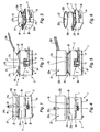
Fig. 1 illustrates a front view of a wok placed on a device according to the preferred embodiment of a device which isn't part of the invention; -
Fig. 2 illustrates a profile sectional view of the wok and of the device ofFig. 1 ; -
Fig. 3 illustrates a perspective view of the wok and of the device ofFig. 1 ; -
Fig. 4 illustrates a front view of a saucepan placed on the device ofFig. 1 ; -
Fig. 5 illustrates a sectional profile view of the saucepan and of the device ofFig. 4 ; -
Fig. 6 illustrates a perspective view of the saucepan and of the device ofFig. 4 ; -
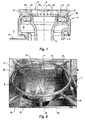
Fig. 7 illustrates a partially sectional view of the burner of the device ofFig. 1 ; and -
Fig. 8 is a picture of the device ofFig. 1 in operation but without any container placed on the grid thereof. - Referring to
Fig. 1 to 8 , adevice 1 for cooking foodstuffs is illustrated. Such adevice 1 is, in the present case, a cooking module arranged for being housed in an appropriate place in a kitchen. Thereby, a kitchen, and more particularly a restaurant kitchen, comprises a succession of modules, each having a function. Themodule 1 is a module for cooking foodstuffs, arranged for allowing for containers of different types to be heated, for example, saucepans, cooking pots and woks. - The
cooking module 1 comprises aparallelepiped shape frame 2, for example made in metal, comprising alower wall 2a and fourside walls 2b, defining a hollowinner volume 3 opened on theupper face thereof 2c. - In the
inner volume 3 of theframe 2 there is mounted a heating source, being here a heat source, in the present case, agas burner 4; such gas devices are generally referred to as "high heat" type gas burners. Theburner 4 is here a double burner. As used herein, a double burner encompasses a burner which, from a unique gas supply, generates two flame patterns, in the present case, a central flame crown 7 and aperipheral flame crown 8; such flame crowns 7, 8 are illustrated on the picture inFig. 8 . Other patterns could be contemplated, for example a single central flame and aperipheral flame crown 8. Theburner 4 is connected with a gas supply line 4', being in turn connected with a gas source, not shown, supplying the latter with combustion gas, as well known to those skilled in the art. The gas could be, for example, a methane-based natural gas or a liquefied petroleum gas type (LPG). - The
burner 4 comprises aninner sleeve 5 concentric with an external sleeve 6 for forming the central flame crown 7 and theperipheral flame crown 8. - The
sleeves 5, 6 each have the shape of a substantially cylindrical part of a common vertical axis 9. Bothsleeves 5, 6 are integral with each other through their bases, connected to each other by a connecting lowerannular portion 10; so, bothsleeves 5, 6 are actually formed by a monobloc part. - A
disc 12, bored in its centre, is mounted on the upper ends of thesleeves 5, 6. Theinner sleeve 5 is opened at its upper end, forming a centralcircular aperture 11 corresponding to the central aperture of thedisc 12. - The
inner wall portion 13 of thedisc 12 forms an inner flame-catcher ring 13. Such aring 13 is bored in its thickness with a plurality ofbores 14.Such bores 14 are evenly distributed angularly to the periphery of theinner ring 13. Each bore 14 extends substantially vertically, slightly sideways from inside to outside, going down and up.Bores 14 open, on the one hand - at the level of their upper aperture - into thecentral aperture 11 of thedisc 12, and on the other hand - at the level of their lower aperture - in thespace 5 provided between theinner sleeve 5 and the external sleeve 6, such aspace 15 being supplied with gas through the line 4', being connected to a hole of the external sleeve 6 opening into such aspace 15. - For commodity reasons and in order to make the description easier, the space provided between the
inner sleeve 5 and the external sleeve 6 will be referred to as "inter-sleeve space 15". - The
external wall portion 16 of thedisc 12 forms an external flame-catcher ring 16. Such aring 16 is bored in its thickness with a plurality ofbores 14. Thebores 17 are evenly distributed angularly to the periphery of theexternal ring 16. Each bore 17 extend sideways from the inside to the outside, going from down to up.Bores 17 open, on the one hand - at the level of their upper aperture - into the periphery of thedisc 12, on the other hand - at the level of their lower aperture - into theinter-sleeve space 15. - The gases present in the
inter-sleeve space 15, supplied by the supplying line 4', are ignited and the produced flames are "caught" by the inner flame-catcher ring 13 and the external flame-catcher ring 16, thus generating a central flame crown 7 and aperipheral flame crown 8, in the present case, respectively substantially vertical and tilted, such as are illustrated on the picture inFig. 8 . - The
bores 17 of the external or the peripheral flame-catcher ring 16 are more tilted relative to the vertical than are thebores 14 of the inner or central flame-catcher ring 13. Thus, thecentral ring 13 generates an almost vertical flame crown 7 while theperipheral ring 16 generates a tiltedflame crown 8. - In operation, flames being formed, it is only needed to supply the
inter-sleeve space 15 for pursuing generating flames. For initiating the combustion, a flame (for example of a match) could be brought closer to the upper aperture of thebores inter-sleeve space 15. - The
cooking module 1 supports, along the upper edges of itsside walls 2b defining theupper aperture 2c, agrid 18 for supporting a container for containing foodstuffs to be cooked by themodule 1. Thegrid 18 is arranged such that containers of different types extend at different distances from theburner 4. In particular, it is arranged such that a container with a bulged bottom (and more particularly, a wok) extends closer to theburner 4 than a container with a flat bottom (and more particularly, a saucepan or a cooking pot). To this end, thegrid 18 comprises here acentral ring 19, fixed to theside walls 2b of thecooking module 1 through connectingbars 20. - Because of the pattern of the
burner 4 with a central flame crown 7 and aperipheral flame crown 8, the heat of theheating source 4 is all the more concentrated on the container as the distance from the container to thesource 4 is smaller. - Thus, the containers with a bulged bottom supported by the
grid 18 extend closer to theburner 4 and thus receive a more concentrated heat than containers with a flat bottom which, when being supported by thegrid 18, extend further from theburner 4 and therefore, receive a more distributed heat. -
Fig. 1 to 3 illustrate thecooking module 1 supporting awok 21 with a bulged bottom andFig. 4 to 6 , thecooking module 1 supporting acooking pot 22 with a flat bottom. - The
wok 21 has a bulged shape, more precisely a spherical one (it forms an opened hollow sphere portion). More precisely, it comprises awall 21b forming abulged bottom 21b, shaped as a portion of sphere, extending from anupper edge 21a, forming the upper aperture of thewok 21, up to alower end surface 21c orbottom surface 21c of thewok 21. Thewok 21 furthermore comprises asleeve 21d fixed to itswall 21 b at the level of itsedge 21 a. - The
cooking pot 22 has a hollow cylindrical shape opened on the upper side. It comprises a cylindrical-shapedside wall 22b, abottom wall 22c and anupper edge 22a forming the upper aperture of thecooking pot 22. It furthermore comprises asleeve 22d fixed to itsside wall 22b. - The diameter of the
ring 19 of the supportinggrid 18 is lower than the diameter of the bottom wall of thecooking pot 22. It is furthermore lower than the diameter of theupper edge 21a of thewok 21. - Because of the relationship between the diameter of the
ring 19 and that of itsupper edge 21a, thewok 21 is in contact with thering 19 along a surface located between itsupper edge 21a and itsbottom surface 21c; in the present case, thewok 21 is supported approximately half height of its bulgedbottom wall 21b. - Because of the relationship between the diameter of the
ring 19 and that of itsbottom wall 22c, thecooking pot 22, on its part, lies, by means of itsbottom wall 22c, on the upper surface of thering 19. - Thus, the
bottom surface 21 c of thewok 21 extends at a smaller distance from theburner 4 than thebottom wall 22 of thecooking pot 22. The heating as received by thewok 21 is thus more concentrated than the heating as received by thecooking pot 22. - Such a difference in the heating concentration, due to the relationship between the dimensions of the
ring 19 of thegrid 18 and those of thewok 21 or thecooking pot 22, is improved by the pattern of the burner 4: as it has a double pattern with a central crown 7 of vertical flames and aperipheral crown 8 of tilted flames, the burner heats thewok 21 in a very concentrated way at the centre of the wok 21 (i.e. on its bottom surface extending in the vicinity of the central crown 7 of the burner 4) and heats thecooking pot 22 in a more distributed way (on its bottom surface extending at a substantially constant distance from theburner 4 and therefore receiving a more distributed heat from the central crown 7 and the peripheral crown 8). - Thus, the heating central portion of the
heating source 4 is all the more enhanced, to the disadvantage of its heating peripheral portion, as the distance from thecontainer source 4 is smaller. The heating central portion of theburner 4 corresponds to the inner flame-catcher ring 13, generating the central flame crown 7. The heating peripheral portion of theburner 4 corresponds to the external flame-catcher ring 16, generating theperipheral flame crown 8. - It should be incidentally noted that, preferably, peripheral flames are sufficiently spaced apart from the
burner 4 central flames, or are short enough, so as to avoid disturbing the flow of combustion products of the central flames. - Thus, it is possible to use the same cooking module for different types of containers, without requiring for dismantling either the burner or the grid. Furthermore, the module meets the regulatory safety standards in so as it forms an appropriate support for each container. In particular, the device is provided with a multi-purpose use without any hazard at the safety level and meeting the energy standardized use specifications: the association of a burner and of a grid allowing them, by means of their respective arrangements, for a hygienic combustion to be obtained with a satisfactory efficiency, for a use with a wok or with a saucepan, more generally in more or less concentrated heating operating modes.
- The specification relates to a particular embodiment of the method and of the cooking device which aren't part of the invention. Obviously, alternative patterns could be contemplated, filling the same function.
- In the invention, the grid is not formed by a ring; according to the invention, a plurality of tilted bars corresponding to the edges of a pyramid are adapted for filling the function of the ring as described in the present application.
- Furthermore, the function aimed at favouring more or less the heating of the central portion with respect to that of the peripheral portion could be filled in various ways. For example, distinct gas supplies could be provided for each portion (central and peripheral), being adapted to set their powers independently one from the other; the ratio is thereby easily set between the power of the central portion and the power of the peripheral portion, allowing to increase all the more said ratio as the distance from the container to the source is smaller.
Claims (3)
- A device for cooking foodstuffs placed in a container (21, 22), comprising a heating source (4) for heating said ontainer (21, 22) and a means (18) for supporting said container (21, 22), arranged for heating said container (21, 22) in an all the more concentrated manner as the distance from the container (21, 22) to the source (4) is smaller,
said device being arranged such that the bottom (21c) of a container with a bulged bottom (21), for example a wok (21), extends closer to the source (4) than the bottom (22c) of a container with a flat bottom (22), for example a saucepan (22),
said device comprising a grid (18) for supporting said container comprising a container-supporting mean (20), arranged such that said container with a bulged bottom (21), for example a wok (21), comes in abutment along a contact surface located between its lower (21c) and upper (21a) end portions, and such that said container with a flat bottom (22), for example a saucepan (22), comes in abutment, by means of the bottom thereof (22c), on the mean (20),
characterized in that said mean (20) is a plurality of tilted bars corresponding to the edges of a pyramid. - A device according to one of claims 1, wherein the heating source comprises a gas burner (4) arranged for generating at least one central flame (7) and a peripheral flame crown (8).
- A device according to claim 2, wherein said at least one central flame (7) is substantially vertical, and said peripheral flame crown (8) is tilted.
Applications Claiming Priority (2)
| Application Number | Priority Date | Filing Date | Title |
|---|---|---|---|
| FR0801107A FR2928203B1 (en) | 2008-02-28 | 2008-02-28 | METHOD AND DEVICE FOR COOKING FOOD |
| PCT/IB2009/050807 WO2009107103A2 (en) | 2008-02-28 | 2009-02-27 | A method and a device for cooking foodstuffs |
Publications (2)
| Publication Number | Publication Date |
|---|---|
| EP2250443A2 EP2250443A2 (en) | 2010-11-17 |
| EP2250443B1 true EP2250443B1 (en) | 2016-02-24 |
Family
ID=39791767
Family Applications (1)
| Application Number | Title | Priority Date | Filing Date |
|---|---|---|---|
| EP09714639.3A Active EP2250443B1 (en) | 2008-02-28 | 2009-02-27 | Device for cooking foodstuffs |
Country Status (4)
| Country | Link |
|---|---|
| EP (1) | EP2250443B1 (en) |
| DE (1) | DE212009000017U1 (en) |
| FR (1) | FR2928203B1 (en) |
| WO (1) | WO2009107103A2 (en) |
Families Citing this family (5)
| Publication number | Priority date | Publication date | Assignee | Title |
|---|---|---|---|---|
| NL2006811C2 (en) * | 2011-01-21 | 2012-07-24 | Intell Properties B V | Multi purpose gas burner. |
| NL2006043C2 (en) * | 2011-01-21 | 2012-07-24 | Intell Properties B V | Multi purpose gas burner. |
| DE102012023436A1 (en) * | 2012-11-30 | 2014-06-05 | German Gabtec Gmbh | Cooking place of a gas stove |
| US10281157B2 (en) | 2016-02-10 | 2019-05-07 | Wolf Appliance, Inc. | Gas cooktop with integrated wok |
| USD812415S1 (en) * | 2016-02-10 | 2018-03-13 | Wolf Appliance, Inc. | Wok burner assembly integrated with a gas cooktop |
Family Cites Families (3)
| Publication number | Priority date | Publication date | Assignee | Title |
|---|---|---|---|---|
| JPS60149818A (en) * | 1984-01-12 | 1985-08-07 | Osaka Gas Co Ltd | Gas burner |
| GB0107566D0 (en) * | 2001-03-27 | 2001-05-16 | Geddes Allen | Safety cooking ring |
| US6935330B1 (en) * | 2003-02-13 | 2005-08-30 | Whirlpool Corporation | Cooking grate with removable central wok ring |
-
2008
- 2008-02-28 FR FR0801107A patent/FR2928203B1/en active Active
-
2009
- 2009-02-27 WO PCT/IB2009/050807 patent/WO2009107103A2/en not_active Ceased
- 2009-02-27 DE DE200921000017 patent/DE212009000017U1/en not_active Expired - Lifetime
- 2009-02-27 EP EP09714639.3A patent/EP2250443B1/en active Active
Also Published As
| Publication number | Publication date |
|---|---|
| FR2928203A1 (en) | 2009-09-04 |
| DE212009000017U1 (en) | 2010-09-23 |
| EP2250443A2 (en) | 2010-11-17 |
| WO2009107103A3 (en) | 2009-11-05 |
| FR2928203B1 (en) | 2010-12-24 |
| WO2009107103A2 (en) | 2009-09-03 |
Similar Documents
| Publication | Publication Date | Title |
|---|---|---|
| US8800543B2 (en) | Diffusion cap burner for gas cooking appliance | |
| US6603099B2 (en) | Multifunction electrical cooking appliance | |
| US20080206437A1 (en) | Combined Steaming/Poaching and Sauce Preparation | |
| US6935330B1 (en) | Cooking grate with removable central wok ring | |
| US20120237647A1 (en) | Multi-functional platform food preparation device | |
| EP2250443A2 (en) | A method and a device for cooking foodstuffs | |
| US20190195505A1 (en) | Cooking range | |
| KR20110001116U (en) | Direct flame type multi-functional cooker | |
| KR20110003992U (en) | A lid of direct flame type cooker with reflective plate to control upward and downward | |
| EP0995950B1 (en) | Domestic cooking hob, with gas burner having variable positioning | |
| KR101713432B1 (en) | Multi-function grill | |
| KR100675917B1 (en) | Cookware using steam | |
| KR102142681B1 (en) | Baking pan | |
| KR20110003628U (en) | Roast pan and simple cooker using the one | |
| KR100494883B1 (en) | Cooking apparatus using two-burner system | |
| KR200484169Y1 (en) | Food counter | |
| US12396589B1 (en) | Portable cooking device | |
| JP2003210332A (en) | Cooking equipment | |
| KR20200111472A (en) | Fireball Structure of a Gas stove | |
| KR200196668Y1 (en) | A roaster having a gas range | |
| CN102141255A (en) | Novel energy-saving stove of gas having a flat top side | |
| JPH0423497Y2 (en) | ||
| KR20170064679A (en) | Removable Composite Cooking Utensils and Roasting Device Using This | |
| KR200433538Y1 (en) | Burner using solid fuel | |
| KR20160013383A (en) | Support plate for gas range |
Legal Events
| Date | Code | Title | Description |
|---|---|---|---|
| PUAI | Public reference made under article 153(3) epc to a published international application that has entered the european phase |
Free format text: ORIGINAL CODE: 0009012 |
|
| 17P | Request for examination filed |
Effective date: 20100727 |
|
| AK | Designated contracting states |
Kind code of ref document: A2 Designated state(s): AT BE BG CH CY CZ DE DK EE ES FI FR GB GR HR HU IE IS IT LI LT LU LV MC MK MT NL NO PL PT RO SE SI SK TR |
|
| AX | Request for extension of the european patent |
Extension state: AL BA RS |
|
| DAX | Request for extension of the european patent (deleted) | ||
| 17Q | First examination report despatched |
Effective date: 20130409 |
|
| GRAP | Despatch of communication of intention to grant a patent |
Free format text: ORIGINAL CODE: EPIDOSNIGR1 |
|
| INTG | Intention to grant announced |
Effective date: 20151102 |
|
| GRAS | Grant fee paid |
Free format text: ORIGINAL CODE: EPIDOSNIGR3 |
|
| GRAA | (expected) grant |
Free format text: ORIGINAL CODE: 0009210 |
|
| AK | Designated contracting states |
Kind code of ref document: B1 Designated state(s): AT BE BG CH CY CZ DE DK EE ES FI FR GB GR HR HU IE IS IT LI LT LU LV MC MK MT NL NO PL PT RO SE SI SK TR |
|
| REG | Reference to a national code |
Ref country code: GB Ref legal event code: FG4D |
|
| REG | Reference to a national code |
Ref country code: CH Ref legal event code: EP |
|
| REG | Reference to a national code |
Ref country code: AT Ref legal event code: REF Ref document number: 776928 Country of ref document: AT Kind code of ref document: T Effective date: 20160315 |
|
| REG | Reference to a national code |
Ref country code: IE Ref legal event code: FG4D |
|
| REG | Reference to a national code |
Ref country code: FR Ref legal event code: PLFP Year of fee payment: 8 |
|
| REG | Reference to a national code |
Ref country code: DE Ref legal event code: R096 Ref document number: 602009036451 Country of ref document: DE |
|
| REG | Reference to a national code |
Ref country code: LT Ref legal event code: MG4D |
|
| REG | Reference to a national code |
Ref country code: NL Ref legal event code: MP Effective date: 20160224 |
|
| REG | Reference to a national code |
Ref country code: AT Ref legal event code: MK05 Ref document number: 776928 Country of ref document: AT Kind code of ref document: T Effective date: 20160224 |
|
| PG25 | Lapsed in a contracting state [announced via postgrant information from national office to epo] |
Ref country code: NO Free format text: LAPSE BECAUSE OF FAILURE TO SUBMIT A TRANSLATION OF THE DESCRIPTION OR TO PAY THE FEE WITHIN THE PRESCRIBED TIME-LIMIT Effective date: 20160524 Ref country code: GR Free format text: LAPSE BECAUSE OF FAILURE TO SUBMIT A TRANSLATION OF THE DESCRIPTION OR TO PAY THE FEE WITHIN THE PRESCRIBED TIME-LIMIT Effective date: 20160525 Ref country code: FI Free format text: LAPSE BECAUSE OF FAILURE TO SUBMIT A TRANSLATION OF THE DESCRIPTION OR TO PAY THE FEE WITHIN THE PRESCRIBED TIME-LIMIT Effective date: 20160224 Ref country code: IT Free format text: LAPSE BECAUSE OF FAILURE TO SUBMIT A TRANSLATION OF THE DESCRIPTION OR TO PAY THE FEE WITHIN THE PRESCRIBED TIME-LIMIT Effective date: 20160224 Ref country code: ES Free format text: LAPSE BECAUSE OF FAILURE TO SUBMIT A TRANSLATION OF THE DESCRIPTION OR TO PAY THE FEE WITHIN THE PRESCRIBED TIME-LIMIT Effective date: 20160224 Ref country code: HR Free format text: LAPSE BECAUSE OF FAILURE TO SUBMIT A TRANSLATION OF THE DESCRIPTION OR TO PAY THE FEE WITHIN THE PRESCRIBED TIME-LIMIT Effective date: 20160224 |
|
| PG25 | Lapsed in a contracting state [announced via postgrant information from national office to epo] |
Ref country code: LV Free format text: LAPSE BECAUSE OF FAILURE TO SUBMIT A TRANSLATION OF THE DESCRIPTION OR TO PAY THE FEE WITHIN THE PRESCRIBED TIME-LIMIT Effective date: 20160224 Ref country code: PT Free format text: LAPSE BECAUSE OF FAILURE TO SUBMIT A TRANSLATION OF THE DESCRIPTION OR TO PAY THE FEE WITHIN THE PRESCRIBED TIME-LIMIT Effective date: 20160624 Ref country code: LT Free format text: LAPSE BECAUSE OF FAILURE TO SUBMIT A TRANSLATION OF THE DESCRIPTION OR TO PAY THE FEE WITHIN THE PRESCRIBED TIME-LIMIT Effective date: 20160224 Ref country code: BE Free format text: LAPSE BECAUSE OF NON-PAYMENT OF DUE FEES Effective date: 20160229 Ref country code: SE Free format text: LAPSE BECAUSE OF FAILURE TO SUBMIT A TRANSLATION OF THE DESCRIPTION OR TO PAY THE FEE WITHIN THE PRESCRIBED TIME-LIMIT Effective date: 20160224 Ref country code: PL Free format text: LAPSE BECAUSE OF FAILURE TO SUBMIT A TRANSLATION OF THE DESCRIPTION OR TO PAY THE FEE WITHIN THE PRESCRIBED TIME-LIMIT Effective date: 20160224 Ref country code: NL Free format text: LAPSE BECAUSE OF FAILURE TO SUBMIT A TRANSLATION OF THE DESCRIPTION OR TO PAY THE FEE WITHIN THE PRESCRIBED TIME-LIMIT Effective date: 20160224 Ref country code: AT Free format text: LAPSE BECAUSE OF FAILURE TO SUBMIT A TRANSLATION OF THE DESCRIPTION OR TO PAY THE FEE WITHIN THE PRESCRIBED TIME-LIMIT Effective date: 20160224 |
|
| REG | Reference to a national code |
Ref country code: DE Ref legal event code: R119 Ref document number: 602009036451 Country of ref document: DE |
|
| REG | Reference to a national code |
Ref country code: CH Ref legal event code: PL |
|
| PG25 | Lapsed in a contracting state [announced via postgrant information from national office to epo] |
Ref country code: EE Free format text: LAPSE BECAUSE OF FAILURE TO SUBMIT A TRANSLATION OF THE DESCRIPTION OR TO PAY THE FEE WITHIN THE PRESCRIBED TIME-LIMIT Effective date: 20160224 Ref country code: LI Free format text: LAPSE BECAUSE OF NON-PAYMENT OF DUE FEES Effective date: 20160229 Ref country code: DK Free format text: LAPSE BECAUSE OF FAILURE TO SUBMIT A TRANSLATION OF THE DESCRIPTION OR TO PAY THE FEE WITHIN THE PRESCRIBED TIME-LIMIT Effective date: 20160224 Ref country code: CH Free format text: LAPSE BECAUSE OF NON-PAYMENT OF DUE FEES Effective date: 20160229 |
|
| PG25 | Lapsed in a contracting state [announced via postgrant information from national office to epo] |
Ref country code: SK Free format text: LAPSE BECAUSE OF FAILURE TO SUBMIT A TRANSLATION OF THE DESCRIPTION OR TO PAY THE FEE WITHIN THE PRESCRIBED TIME-LIMIT Effective date: 20160224 Ref country code: CZ Free format text: LAPSE BECAUSE OF FAILURE TO SUBMIT A TRANSLATION OF THE DESCRIPTION OR TO PAY THE FEE WITHIN THE PRESCRIBED TIME-LIMIT Effective date: 20160224 Ref country code: RO Free format text: LAPSE BECAUSE OF FAILURE TO SUBMIT A TRANSLATION OF THE DESCRIPTION OR TO PAY THE FEE WITHIN THE PRESCRIBED TIME-LIMIT Effective date: 20160224 |
|
| REG | Reference to a national code |
Ref country code: IE Ref legal event code: MM4A |
|
| PG25 | Lapsed in a contracting state [announced via postgrant information from national office to epo] |
Ref country code: BE Free format text: LAPSE BECAUSE OF FAILURE TO SUBMIT A TRANSLATION OF THE DESCRIPTION OR TO PAY THE FEE WITHIN THE PRESCRIBED TIME-LIMIT Effective date: 20160224 |
|
| PLBE | No opposition filed within time limit |
Free format text: ORIGINAL CODE: 0009261 |
|
| STAA | Information on the status of an ep patent application or granted ep patent |
Free format text: STATUS: NO OPPOSITION FILED WITHIN TIME LIMIT |
|
| GBPC | Gb: european patent ceased through non-payment of renewal fee |
Effective date: 20160524 |
|
| PG25 | Lapsed in a contracting state [announced via postgrant information from national office to epo] |
Ref country code: IE Free format text: LAPSE BECAUSE OF NON-PAYMENT OF DUE FEES Effective date: 20160227 Ref country code: DE Free format text: LAPSE BECAUSE OF NON-PAYMENT OF DUE FEES Effective date: 20160901 |
|
| 26N | No opposition filed |
Effective date: 20161125 |
|
| REG | Reference to a national code |
Ref country code: FR Ref legal event code: PLFP Year of fee payment: 9 |
|
| PG25 | Lapsed in a contracting state [announced via postgrant information from national office to epo] |
Ref country code: SI Free format text: LAPSE BECAUSE OF FAILURE TO SUBMIT A TRANSLATION OF THE DESCRIPTION OR TO PAY THE FEE WITHIN THE PRESCRIBED TIME-LIMIT Effective date: 20160224 Ref country code: BG Free format text: LAPSE BECAUSE OF FAILURE TO SUBMIT A TRANSLATION OF THE DESCRIPTION OR TO PAY THE FEE WITHIN THE PRESCRIBED TIME-LIMIT Effective date: 20160524 |
|
| PG25 | Lapsed in a contracting state [announced via postgrant information from national office to epo] |
Ref country code: GB Free format text: LAPSE BECAUSE OF NON-PAYMENT OF DUE FEES Effective date: 20160524 |
|
| PG25 | Lapsed in a contracting state [announced via postgrant information from national office to epo] |
Ref country code: MT Free format text: LAPSE BECAUSE OF FAILURE TO SUBMIT A TRANSLATION OF THE DESCRIPTION OR TO PAY THE FEE WITHIN THE PRESCRIBED TIME-LIMIT Effective date: 20160224 |
|
| REG | Reference to a national code |
Ref country code: FR Ref legal event code: PLFP Year of fee payment: 10 |
|
| PG25 | Lapsed in a contracting state [announced via postgrant information from national office to epo] |
Ref country code: HU Free format text: LAPSE BECAUSE OF FAILURE TO SUBMIT A TRANSLATION OF THE DESCRIPTION OR TO PAY THE FEE WITHIN THE PRESCRIBED TIME-LIMIT; INVALID AB INITIO Effective date: 20090227 Ref country code: CY Free format text: LAPSE BECAUSE OF FAILURE TO SUBMIT A TRANSLATION OF THE DESCRIPTION OR TO PAY THE FEE WITHIN THE PRESCRIBED TIME-LIMIT Effective date: 20160224 |
|
| PG25 | Lapsed in a contracting state [announced via postgrant information from national office to epo] |
Ref country code: MC Free format text: LAPSE BECAUSE OF FAILURE TO SUBMIT A TRANSLATION OF THE DESCRIPTION OR TO PAY THE FEE WITHIN THE PRESCRIBED TIME-LIMIT Effective date: 20160224 Ref country code: LU Free format text: LAPSE BECAUSE OF NON-PAYMENT OF DUE FEES Effective date: 20160227 Ref country code: MK Free format text: LAPSE BECAUSE OF FAILURE TO SUBMIT A TRANSLATION OF THE DESCRIPTION OR TO PAY THE FEE WITHIN THE PRESCRIBED TIME-LIMIT Effective date: 20160224 Ref country code: MT Free format text: LAPSE BECAUSE OF FAILURE TO SUBMIT A TRANSLATION OF THE DESCRIPTION OR TO PAY THE FEE WITHIN THE PRESCRIBED TIME-LIMIT Effective date: 20160229 Ref country code: IS Free format text: LAPSE BECAUSE OF FAILURE TO SUBMIT A TRANSLATION OF THE DESCRIPTION OR TO PAY THE FEE WITHIN THE PRESCRIBED TIME-LIMIT Effective date: 20160224 Ref country code: TR Free format text: LAPSE BECAUSE OF FAILURE TO SUBMIT A TRANSLATION OF THE DESCRIPTION OR TO PAY THE FEE WITHIN THE PRESCRIBED TIME-LIMIT Effective date: 20160224 |
|
| P01 | Opt-out of the competence of the unified patent court (upc) registered |
Effective date: 20231101 |
|
| PGFP | Annual fee paid to national office [announced via postgrant information from national office to epo] |
Ref country code: FR Payment date: 20260225 Year of fee payment: 18 |