EP2250304B1 - Protective textile sleeve having high edge abrasion resistance and method of construction - Google Patents
Protective textile sleeve having high edge abrasion resistance and method of construction Download PDFInfo
- Publication number
- EP2250304B1 EP2250304B1 EP09716669.8A EP09716669A EP2250304B1 EP 2250304 B1 EP2250304 B1 EP 2250304B1 EP 09716669 A EP09716669 A EP 09716669A EP 2250304 B1 EP2250304 B1 EP 2250304B1
- Authority
- EP
- European Patent Office
- Prior art keywords
- yarns
- warp
- fill
- sleeve
- monofilament
- Prior art date
- Legal status (The legal status is an assumption and is not a legal conclusion. Google has not performed a legal analysis and makes no representation as to the accuracy of the status listed.)
- Active
Links
Images

Classifications
-
- D—TEXTILES; PAPER
- D03—WEAVING
- D03D—WOVEN FABRICS; METHODS OF WEAVING; LOOMS
- D03D1/00—Woven fabrics designed to make specified articles
- D03D1/0035—Protective fabrics
- D03D1/0043—Protective fabrics for elongated members, i.e. sleeves
-
- D—TEXTILES; PAPER
- D03—WEAVING
- D03D—WOVEN FABRICS; METHODS OF WEAVING; LOOMS
- D03D15/00—Woven fabrics characterised by the material, structure or properties of the fibres, filaments, yarns, threads or other warp or weft elements used
- D03D15/20—Woven fabrics characterised by the material, structure or properties of the fibres, filaments, yarns, threads or other warp or weft elements used characterised by the material of the fibres or filaments constituting the yarns or threads
- D03D15/292—Conjugate, i.e. bi- or multicomponent, fibres or filaments
-
- D—TEXTILES; PAPER
- D03—WEAVING
- D03D—WOVEN FABRICS; METHODS OF WEAVING; LOOMS
- D03D1/00—Woven fabrics designed to make specified articles
- D03D1/0035—Protective fabrics
- D03D1/0041—Cut or abrasion resistant
-
- D—TEXTILES; PAPER
- D03—WEAVING
- D03D—WOVEN FABRICS; METHODS OF WEAVING; LOOMS
- D03D13/00—Woven fabrics characterised by the special disposition of the warp or weft threads, e.g. with curved weft threads, with discontinuous warp threads, with diagonal warp or weft
- D03D13/004—Woven fabrics characterised by the special disposition of the warp or weft threads, e.g. with curved weft threads, with discontinuous warp threads, with diagonal warp or weft with weave pattern being non-standard or providing special effects
-
- D—TEXTILES; PAPER
- D03—WEAVING
- D03D—WOVEN FABRICS; METHODS OF WEAVING; LOOMS
- D03D15/00—Woven fabrics characterised by the material, structure or properties of the fibres, filaments, yarns, threads or other warp or weft elements used
- D03D15/20—Woven fabrics characterised by the material, structure or properties of the fibres, filaments, yarns, threads or other warp or weft elements used characterised by the material of the fibres or filaments constituting the yarns or threads
- D03D15/283—Woven fabrics characterised by the material, structure or properties of the fibres, filaments, yarns, threads or other warp or weft elements used characterised by the material of the fibres or filaments constituting the yarns or threads synthetic polymer-based, e.g. polyamide or polyester fibres
-
- D—TEXTILES; PAPER
- D03—WEAVING
- D03D—WOVEN FABRICS; METHODS OF WEAVING; LOOMS
- D03D3/00—Woven fabrics characterised by their shape
- D03D3/02—Tubular fabrics
-
- D—TEXTILES; PAPER
- D07—ROPES; CABLES OTHER THAN ELECTRIC
- D07B—ROPES OR CABLES IN GENERAL
- D07B1/00—Constructional features of ropes or cables
- D07B1/14—Ropes or cables with incorporated auxiliary elements, e.g. for marking, extending throughout the length of the rope or cable
-
- H—ELECTRICITY
- H02—GENERATION; CONVERSION OR DISTRIBUTION OF ELECTRIC POWER
- H02G—INSTALLATION OF ELECTRIC CABLES OR LINES, OR OF COMBINED OPTICAL AND ELECTRIC CABLES OR LINES
- H02G3/00—Installations of electric cables or lines or protective tubing therefor in or on buildings, equivalent structures or vehicles
- H02G3/02—Details
- H02G3/04—Protective tubing or conduits, e.g. cable ladders or cable troughs
- H02G3/0462—Tubings, i.e. having a closed section
- H02G3/0481—Tubings, i.e. having a closed section with a circular cross-section
-
- D—TEXTILES; PAPER
- D10—INDEXING SCHEME ASSOCIATED WITH SUBLASSES OF SECTION D, RELATING TO TEXTILES
- D10B—INDEXING SCHEME ASSOCIATED WITH SUBLASSES OF SECTION D, RELATING TO TEXTILES
- D10B2331/00—Fibres made from polymers obtained otherwise than by reactions only involving carbon-to-carbon unsaturated bonds, e.g. polycondensation products
- D10B2331/04—Fibres made from polymers obtained otherwise than by reactions only involving carbon-to-carbon unsaturated bonds, e.g. polycondensation products polyesters, e.g. polyethylene terephthalate [PET]
-
- D—TEXTILES; PAPER
- D10—INDEXING SCHEME ASSOCIATED WITH SUBLASSES OF SECTION D, RELATING TO TEXTILES
- D10B—INDEXING SCHEME ASSOCIATED WITH SUBLASSES OF SECTION D, RELATING TO TEXTILES
- D10B2401/00—Physical properties
- D10B2401/04—Heat-responsive characteristics
- D10B2401/041—Heat-responsive characteristics thermoplastic; thermosetting
Definitions
- This invention relates generally to protective sleeving for elongate members, and more particularly to woven textile sleeves.
- Elongate members such as wires or wire harnesses commonly require protection from potential external sources of abrasion. Accordingly, it is common to dispose a protective sleeve over the elongate members to provide protection against damage from abrasion and other potentially harmful conditions, such as contamination. It is known to use convolute or corrugated tubing to protect elongate members against abrasion, particularly if the potential for abrasion is relatively severe, such as from passing the elongate members through an opening having sharp corners or edges. Unfortunately, although corrugated tubing can provide the relatively good protection against abrasion, the tubing is relatively costly to manufacture, and it is typically stiff and thus, it can be difficult to route over serpentine paths or around corners.
- the rigid walls of the corrugated tubing can provide an internal source of abrasion to the very elongate members it is intended to protect, particularly if contaminates, such as oil and sand, come between the elongate members and the inner wall of the tubing.
- Sharp surfaces that come into contact with the textile sleeve wall in a generally perpendicular direction are particularly damaging to the fabric of the sleeve. Over time, if the wall is cut by the sharp edge, then the elongate members become exposed and unprotected.
- a textile sleeve for protecting elongate members which sleeve includes both monofilament and multifilament yarns woven in a lengthwise or warp direction and a widthwise or fill direction is disclosed in US2006/016507 .
- the present invention is characterised in that the warp multifilaments and monofilaments are woven in a warp-faced pattern with the fill multifilament and monofilament yarns.
- the warp multifilaments and monofilaments may float over 2 or more of fill yarns to provide the sleeve with increased flexibility.
- the warp monofilaments provide the sleeve with increased abrasion resistance, while at the same time, the warp multifilaments provide the sleeve with increased flexibility and coverage protection for the elongate members within a cavity of the sleeve.
- the fill monofilaments provide the sleeve with increased abrasion resistance and the fill multifilaments provide the sleeve with increased flexibility and coverage protection.
- the warp multifilament and monofilament yarns are woven in a twill, warp-faced pattern.
- the warp-faced twill pattern can be balanced, having the warp yarns floating over and under the same number of fill yarns.
- the warp-faced twill pattern can be imbalanced, thereby having the warp yarns floating over one number of fill yarns and being woven under a different number of fill yarns.
- the multifilament and monofilament fill yarns can be dual inserted.
- the warp multifilament yarns and the warp monofilament yarns can be incorporated in a ratio of about 2:1, respectively.
- a textile sleeve constructed in accordance with the invention has a high level abrasion resistance to external sources of abrasion, such as sharp edges, while also providing increased levels of abrasion resistance to the elongate members within the sleeve, such as from contaminants that become between the sleeve and the elongate members.
- the sleeves constructed in accordance with the invention while providing high levels of protection against abrasion, are also relatively flexible to allow them to be laid over winding paths and around sharp corners.
- sleeves constructed in accordance with the invention are economical in manufacture and in use, and have a long and useful life.
- FIGS 1 and 2 illustrate textile sleeves 10, 110, respectively, constructed in accordance with presently preferred embodiments for protecting elongate members 12, such as a wire harness, for example.
- elongate members 12 such as a wire harness
- FIG. 1 illustrates textile sleeves 10, 110, respectively, constructed in accordance with presently preferred embodiments for protecting elongate members 12, such as a wire harness, for example.
- Each of the sleeves 10, 110 is discussed hereafter using the same reference numerals to identify the structure of their respective walls 14, with the notable difference between the sleeves 10, 110 being that the sleeve 10 is woven having an "open" wall construction, while the sleeve 110 is woven having a "closed” wall construction.
- the wall 14 is woven from both monofilament and multifilament yarns, wherein the monofilament and multifilament yarns are woven both in a lengthwise or warp direction and a widthwise or fill direction extending about a circumference of the sleeves 10, 110.
- the warp multifilament yarns 16 and the warp monofilaments yarns 18 are woven in a warp-faced pattern in interlaced fashion with the fill multifilament yarns 20 and the fill monofilament yarns 22.
- the warp multifilament yarns 16 and warp monofilament yarns 18 both float over 2 or more of the fill yams 20, 22 to provide the sleeve 10 with increased flexibility.
- the warp monofilament yarns 18 can be provided of any suitable material, such as polyester, e.g. PET, and in any desired diameter to provide the sleeve with the desired level of abrasion resistance, such as from edges or other surfaces abutting the sleeve.
- the warp multifilament yarns 16 can be provided of any suitable material, such as polyester, e.g. PET, and having any desired tex to provide the sleeve with increased flexibility and coverage protection for the elongate members 12 being protected within a cavity 24 of the sleeves 10, 110.
- the warp and fill monofilament yarns 18, 22 provide the sleeves 10, 110 with increased abrasion resistance and the warp and fill multifilament yarns 16, 20 provide the sleeves 10, 110 with increased flexibility, softness and coverage protection to protect the elongate members 12.
- the wall 14 of the sleeve 10 is woven having an "open" wall construction, thereby having a axially extending, lengthwise slit 26 extending along a longitudinal axis 27 over the full length of the sleeve 10.
- the wall 14 of the sleeve 110 is woven having a "closed", circumferentially seamless construction, thus having a circumferentially continuous and uninterrupted wall.
- the sleeve 10 can be constructed on either narrow or broad looms, as desired.
- the sleeve is constructed having an open wall configuration
- opposite edges 28, 30 of the wall 14 are preferably arranged in overlapping relation to one another to completely encapsulate the elongate members 12 about the circumference of the sleeve within the sleeve cavity 24.
- the wall 14 can be constructed as a self-wrapping wall, wherein the wall 14 is self-curling to take on its tubular configuration absent some external force causing the wall 14 to be opened along its length.
- the bias imparted in the self-wrapping wall 14 can be imparted via a heat-setting process, wherein the fill monofilament yarns of the sleeve 10 are heat-set to take on a predetermined self-wrapping tubular configuration and/or by tensioning the yarns during the weaving process. Otherwise, the wall 14 could be wrapped and fastened in its tubular configuration using any suitable fastening mechanism, such as tape, a hook and loop mechanism, snaps, or the like.
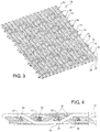
- the wall 14 can be constructed using a twill weave pattern, wherein the wall is represented here, by way of example and without limitation, as having a balanced 2x2 left hand, warp-faced twill weave pattern. It should be recognized that the weave pattern could be different than illustrated. Accordingly, the weave pattern could be provided as a left or right hand pattern, and further, the weave pattern could be imbalanced, wherein the warp yarns 16, 18 could float over one number of the fill yarns 20, 22, such as 2, 3 or 4 fill yarns, for example, and be woven under a different number of the fill yarns.
- the warp yarns 16, 18 in one presently preferred embodiment are provided in a ratio of about 2 warp multifilament yarns 16 to 1 warp monofilament yarn 18 to provide the sleeve 10 with the desired abrasion resistance, while also providing the sleeve 10 with flexibility, such that the sleeve can be readily routed around corners.
- the number of ends of warp multifilament yarns 16 can be about 70-80, while the number of ends of warp monofilament yarn 18 can be about 35-40.
- the multifilament yarns 16 can be provided having about a 900-1400 tex and the monofilament yarns 18 can be provided having about a 0.20-0.30 mm diameter.
- the weft or fill yarns 20, 22 are provided in a dual insertion fashion to provide pairs of the fill yarns spaced axially from one another with one fill yarn 20 being adjacent and closely abutting another fill yarn 22.
- the fill yarns 20, 22 are inserted having a picks per inch (PPI) of about 14-18, wherein the same types and sizes of yarn can be used as used for the warp yarns 16, 18, if desired.
- the fill monofilament yarns 22 provide the sleeve 10 with an increased ability to resist abrasion, and possibly a self-curling bias, as discussed above, while the fill multifilament yarns 20 provide the sleeve 10 with an increased flexibility and coverage to further protect against the ingress of contamination into the sleeve cavity 24.
- Abrasion test Result (Size: 13mm) [Unit: cycle] Sample Corrogated Tube Prior Art Textile Sleeve Presently Preferred Embodiment Mass: 400g 1 4.000 293 11,700 Thickness: 2mm Stroke width: 51mm 2 5,000 416 16,355 Frequency: 150cycles / min 3 12,666 Average 4,500 355 13,574
- the corrugated tube demonstrated a resistance to abrasion over an average of 4,500 cycles
- the prior art textile sleeve demonstrated a resistance to abrasion over an average of 355 cycles
- the sleeve 10 demonstrated a resistance to abrasion over an average of 13,574 cycles. Accordingly, the sleeve 10 far outperformed both the corrugated tube (about 3 times as great of an ability to resist abrasion) and the prior art textile sleeve (about 38 times as great of an ability to resist abrasion).
- the prior art textile sleeve was woven having only monofilaments in the warp direction and only multifilaments in the fill direction.
- the sleeves 10, 110 can be constructed other than as expressly described above in the presently preferred embodiment, and that other types and sizes of yarns can be used in the construction of the sleeves 10, 110. It is, therefore, to be understood that within the scope of the appended claims, the invention may be practiced otherwise than as specifically described.
Landscapes
- Engineering & Computer Science (AREA)
- Textile Engineering (AREA)
- Architecture (AREA)
- Civil Engineering (AREA)
- Structural Engineering (AREA)
- Woven Fabrics (AREA)
Description
- This invention relates generally to protective sleeving for elongate members, and more particularly to woven textile sleeves.
- Elongate members, such as wires or wire harnesses commonly require protection from potential external sources of abrasion. Accordingly, it is common to dispose a protective sleeve over the elongate members to provide protection against damage from abrasion and other potentially harmful conditions, such as contamination. It is known to use convolute or corrugated tubing to protect elongate members against abrasion, particularly if the potential for abrasion is relatively severe, such as from passing the elongate members through an opening having sharp corners or edges. Unfortunately, although corrugated tubing can provide the relatively good protection against abrasion, the tubing is relatively costly to manufacture, and it is typically stiff and thus, it can be difficult to route over serpentine paths or around corners. In addition, the rigid walls of the corrugated tubing can provide an internal source of abrasion to the very elongate members it is intended to protect, particularly if contaminates, such as oil and sand, come between the elongate members and the inner wall of the tubing.
- As a result of the drawbacks of corrugated tubing, of which some are discussed above, other types of protective tubing are used to protect elongate members, such as textile sleeves. Textile sleeves are typically much easier to route over serpentine paths and can be less expensive to manufacture than corrugated sleeving. In addition, textile sleeves are typically softer and thus, present less of a likelihood of causing abrasion damaged to the elongate members. However, a recognized drawback to textile sleeves is that they have a reduced capacity to provide abrasion resistance protection to the elongate members from an external source of abrasion, particularly sharp corners and edges. Sharp surfaces that come into contact with the textile sleeve wall in a generally perpendicular direction are particularly damaging to the fabric of the sleeve. Over time, if the wall is cut by the sharp edge, then the elongate members become exposed and unprotected.
- Accordingly, benefits and drawbacks are associated with both hard shelled tubing, such as convolute metal or plastic tubing and textile sleeves. What is needed is a protective sleeving that provides the benefits of both, while eliminating their potential drawbacks.
US2005/0124249 andDE10212918 disclose textile sleeves. - A textile sleeve for protecting elongate members, which sleeve includes both monofilament and multifilament yarns woven in a lengthwise or warp direction and a widthwise or fill direction is disclosed in
US2006/016507 . The present invention is characterised in that the warp multifilaments and monofilaments are woven in a warp-faced pattern with the fill multifilament and monofilament yarns. As such, the warp multifilaments and monofilaments may float over 2 or more of fill yarns to provide the sleeve with increased flexibility. The warp monofilaments provide the sleeve with increased abrasion resistance, while at the same time, the warp multifilaments provide the sleeve with increased flexibility and coverage protection for the elongate members within a cavity of the sleeve. The fill monofilaments provide the sleeve with increased abrasion resistance and the fill multifilaments provide the sleeve with increased flexibility and coverage protection. - In accordance with certain embodiments of the invention, the warp multifilament and monofilament yarns are woven in a twill, warp-faced pattern.
- In accordance with certain embodiments of the invention, the warp-faced twill pattern can be balanced, having the warp yarns floating over and under the same number of fill yarns.
- In accordance with certain other embodiments of the invention, the warp-faced twill pattern can be imbalanced, thereby having the warp yarns floating over one number of fill yarns and being woven under a different number of fill yarns.
- In accordance with other embodiments of the invention, the multifilament and monofilament fill yarns can be dual inserted.
- In accordance with yet other embodiments of the invention, the warp multifilament yarns and the warp monofilament yarns can be incorporated in a ratio of about 2:1, respectively.
- A textile sleeve constructed in accordance with the invention has a high level abrasion resistance to external sources of abrasion, such as sharp edges, while also providing increased levels of abrasion resistance to the elongate members within the sleeve, such as from contaminants that become between the sleeve and the elongate members. The sleeves constructed in accordance with the invention, while providing high levels of protection against abrasion, are also relatively flexible to allow them to be laid over winding paths and around sharp corners. In addition, sleeves constructed in accordance with the invention are economical in manufacture and in use, and have a long and useful life.
- These and other aspects, features and advantages of the invention will become readily apparent when considered in connection with the following detailed description of presently preferred embodiments and best mode, appended claims and accompanying drawings, in which:
-
Figure 1 is a schematic perspective view of a protective sleeve constructed in accordance with one presently preferred embodiment shown protecting elongate members; -
Figure 2 is a schematic perspective view of a protective sleeve constructed in accordance with another presently preferred embodiment shown protecting elongate members; -
Figure 3 is a schematic partial view of an encircled area 3 of a wall of the sleeves ofFigures 1 and 2 ; and -
Figure 4 is an enlarged schematic partial side view showing a weave pattern of the walls ofFigure 3 . - Referring in more detail to the drawings,
Figures 1 and 2 illustrate textile sleeves elongate members 12, such as a wire harness, for example. Each of thesleeves respective walls 14, with the notable difference between thesleeves sleeve 10 is woven having an "open" wall construction, while thesleeve 110 is woven having a "closed" wall construction. Thewall 14 is woven from both monofilament and multifilament yarns, wherein the monofilament and multifilament yarns are woven both in a lengthwise or warp direction and a widthwise or fill direction extending about a circumference of thesleeves Figure 4 , thewarp multifilament yarns 16 and thewarp monofilaments yarns 18 are woven in a warp-faced pattern in interlaced fashion with thefill multifilament yarns 20 and thefill monofilament yarns 22. As such, the warp multifilament yarns 16 andwarp monofilament yarns 18 both float over 2 or more of thefill yams sleeve 10 with increased flexibility. Thewarp monofilament yarns 18 can be provided of any suitable material, such as polyester, e.g. PET, and in any desired diameter to provide the sleeve with the desired level of abrasion resistance, such as from edges or other surfaces abutting the sleeve. Thewarp multifilament yarns 16 can be provided of any suitable material, such as polyester, e.g. PET, and having any desired tex to provide the sleeve with increased flexibility and coverage protection for theelongate members 12 being protected within acavity 24 of thesleeves fill monofilament yarns sleeves multifilament yarns sleeves elongate members 12. - As shown in
Figure 1 , thewall 14 of thesleeve 10 is woven having an "open" wall construction, thereby having a axially extending, lengthwiseslit 26 extending along alongitudinal axis 27 over the full length of thesleeve 10. Otherwise, as shown inFigure 2 , thewall 14 of thesleeve 110 is woven having a "closed", circumferentially seamless construction, thus having a circumferentially continuous and uninterrupted wall. In either case, thesleeve 10 can be constructed on either narrow or broad looms, as desired. Wherein the sleeve is constructed having an open wall configuration,opposite edges wall 14 are preferably arranged in overlapping relation to one another to completely encapsulate theelongate members 12 about the circumference of the sleeve within thesleeve cavity 24. Otherwise, thewall 14 can be constructed as a self-wrapping wall, wherein thewall 14 is self-curling to take on its tubular configuration absent some external force causing thewall 14 to be opened along its length. The bias imparted in the self-wrappingwall 14 can be imparted via a heat-setting process, wherein the fill monofilament yarns of thesleeve 10 are heat-set to take on a predetermined self-wrapping tubular configuration and/or by tensioning the yarns during the weaving process. Otherwise, thewall 14 could be wrapped and fastened in its tubular configuration using any suitable fastening mechanism, such as tape, a hook and loop mechanism, snaps, or the like. - As shown in
Figure 3 , thewall 14 can be constructed using a twill weave pattern, wherein the wall is represented here, by way of example and without limitation, as having a balanced 2x2 left hand, warp-faced twill weave pattern. It should be recognized that the weave pattern could be different than illustrated. Accordingly, the weave pattern could be provided as a left or right hand pattern, and further, the weave pattern could be imbalanced, wherein thewarp yarns fill yarns - The
warp yarns warp multifilament yarns 16 to 1warp monofilament yarn 18 to provide thesleeve 10 with the desired abrasion resistance, while also providing thesleeve 10 with flexibility, such that the sleeve can be readily routed around corners. For example, in a sleeve having an unfolded, flattened tape width of about 67 mm, the number of ends ofwarp multifilament yarns 16 can be about 70-80, while the number of ends ofwarp monofilament yarn 18 can be about 35-40. In this example, and without limitation, themultifilament yarns 16 can be provided having about a 900-1400 tex and themonofilament yarns 18 can be provided having about a 0.20-0.30 mm diameter. - As best shown in
Figure 4 , the weft or fillyarns fill yarn 20 being adjacent and closely abutting anotherfill yarn 22. In the 67 mm wide embodiment described above, thefill yarns warp yarns fill monofilament yarns 22 provide thesleeve 10 with an increased ability to resist abrasion, and possibly a self-curling bias, as discussed above, while thefill multifilament yarns 20 provide thesleeve 10 with an increased flexibility and coverage to further protect against the ingress of contamination into thesleeve cavity 24. - In a test performed to compare the abrasion resistance between a corrugated tube, a prior art textile sleeve and a
sleeve 10 constructed in accordance with the invention, the following test results were obtained.Abrasion test Result (Size: 13mm) [Unit: cycle] Sample Corrogated Tube Prior Art Textile Sleeve Presently Preferred Embodiment Mass: 400g 1 4.000 293 11,700 Thickness: 2mm Stroke width: 51mm 2 5,000 416 16,355 Frequency: 150cycles / min 3 12,666 Average 4,500 355 13,574 - As illustrated, the corrugated tube demonstrated a resistance to abrasion over an average of 4,500 cycles, the prior art textile sleeve demonstrated a resistance to abrasion over an average of 355 cycles, and the
sleeve 10 demonstrated a resistance to abrasion over an average of 13,574 cycles. Accordingly, thesleeve 10 far outperformed both the corrugated tube (about 3 times as great of an ability to resist abrasion) and the prior art textile sleeve (about 38 times as great of an ability to resist abrasion). It should be noted that the prior art textile sleeve was woven having only monofilaments in the warp direction and only multifilaments in the fill direction. - Obviously, many modifications and variations of the present invention are possible in light of the above teachings. For example, it needs to be understood that the
sleeves sleeves
Claims (14)
- A textile sleeve (10; 110) for protecting elongate members (12), comprising:an elongate wall (14) having warp multifilament yarns (16) and warp monofilament yarns (18) woven with fill multifilament yarns (20) and fill monofilament yarns (22),characterised in that said warp multifilament yarns (16) and said warp monofilament yarns (18) are woven in a warp-faced pattern in relation to said fill multifilament yarns (20) and said fill monofilament yarns (22) such that the warp multifilaments and mono filaments (16, 18) float over two or more of the fill yarns (20, 22).
- The textile sleeve (10; 110) of claim 1 wherein each of said fill multifilament yarns (20) is inserted with one of said fill monofilament yarns (22) to form dual inserted pairs of fill yarns.
- The textile sleeve (10; 110) of claim 2 wherein 2 of said warp multifilament yarns (16) are provided for every 1 of said warp monofilament yarns (18).
- The textile sleeve (10; 110) of claim 2 wherein said warp multifilament yarns (16) and said warp monofilament yarns (18) are woven in a balanced twill weave.
- The textile sleeve (10; 110) of claim 1 wherein said wall (14) is a closed, circumferentially continuous wall.
- The textile sleeve (10; 110) of claim 1 wherein said wall (14) is an open wall having a slit (26) provided by opposite edges (28, 30) extending along a longitudinal axis (27) of said sleeve.
- The textile sleeve (10; 110) of claim 6 wherein said fill monofilament yarns (22) are heat-set into a self-biased curled configuration to bring said opposite edges (28, 30) in overlapping relation with one another.
- A method of constructing a textile sleeve (10; 110) for protecting elongate members (12), comprising:weaving multifilament yarns (16, 20) and monofilaments yarns (18, 22) with one another with a plurality of said multifilament yarns and said monofilament yarns providing warp yarns (16, 18) extending along a length of the sleeve and a plurality of said multifilament yarns and said monofilament yarns providing fill yarns (20, 22) extending about a circumference of the sleeve,characterised in that said warp yarns (16, 18) are woven in a warp-faced pattern in relation to said fill yarns (20, 22) such that the warp multifilaments and monofilaments (16, 18) float over two or more of the fill yarns (20, 22).
- The method of claim 8 further including inserting said fill yarns (20, 22) in pairs with one of said fill monofilament yarns (22) being inserted with one of said fill multifilament yarns (20).
- The method of claim 9 further including weaving 2 of said warp multifilament yarns (16) for every 1 of said warp monofilament yarns (18).
- The method of claim 8 further including weaving said warp yarns (16, 18) in a twill pattern.
- The method of claim 9 further including weaving said sleeve (10; 110) having a wall (14) with a closed, circumferentially continuous wall.
- The method of claim 9 further including weaving said sleeve (10; 110) having a wall (14) with a slit (26) provided by opposite edges (28, 30) extending along a longitudinal axis (27) of said sleeve.
- The method of claim 8 further including heat-setting said fill monofilament yarns (22) into a self-biased curled configuration to bring said opposite edges (28, 30) in overlapping relation with one another.
Applications Claiming Priority (3)
| Application Number | Priority Date | Filing Date | Title |
|---|---|---|---|
| US3266308P | 2008-02-29 | 2008-02-29 | |
| US12/392,156 US8701716B2 (en) | 2008-02-29 | 2009-02-25 | Protective textile sleeve having high edge abrasion resistance and method of construction |
| PCT/US2009/035213 WO2009111253A2 (en) | 2008-02-29 | 2009-02-26 | Protective textile sleeve having high edge abrasion resistance and method of construction |
Publications (3)
| Publication Number | Publication Date |
|---|---|
| EP2250304A2 EP2250304A2 (en) | 2010-11-17 |
| EP2250304A4 EP2250304A4 (en) | 2014-07-23 |
| EP2250304B1 true EP2250304B1 (en) | 2019-05-22 |
Family
ID=41012256
Family Applications (1)
| Application Number | Title | Priority Date | Filing Date |
|---|---|---|---|
| EP09716669.8A Active EP2250304B1 (en) | 2008-02-29 | 2009-02-26 | Protective textile sleeve having high edge abrasion resistance and method of construction |
Country Status (6)
| Country | Link |
|---|---|
| US (2) | US8701716B2 (en) |
| EP (1) | EP2250304B1 (en) |
| JP (1) | JP5583607B2 (en) |
| KR (1) | KR101588181B1 (en) |
| CN (1) | CN102007239B (en) |
| WO (1) | WO2009111253A2 (en) |
Families Citing this family (52)
| Publication number | Priority date | Publication date | Assignee | Title |
|---|---|---|---|---|
| US8701716B2 (en) * | 2008-02-29 | 2014-04-22 | Federal-Mogul Corporation | Protective textile sleeve having high edge abrasion resistance and method of construction |
| MY160176A (en) * | 2008-06-23 | 2017-02-28 | Wesco Equity Corp | Communications cable with fabric sleeve |
| US8925592B2 (en) | 2009-06-11 | 2015-01-06 | Federal-Mogul Powertrain, Inc. | Flexible, abrasion resistant textile sleeve and method of construction thereof |
| JP6279832B2 (en) * | 2009-06-11 | 2018-02-14 | フェデラル−モーグル・パワートレイン・リミテッド・ライアビリティ・カンパニーFederal−Mogul Powertrain Llc | Flexible, abrasion-resistant textile sleeve and its construction method |
| CN102667964B (en) * | 2009-10-07 | 2015-06-17 | 费德罗-莫格尔动力系公司 | Flexible textile sleeve with end fray resistant, protective coating and method of construction thereof |
| WO2012024272A1 (en) * | 2010-08-16 | 2012-02-23 | Federal-Mogul Powertrain, Inc. | Non-kinking self-wrapping woven sleeve and method of construction thereof |
| EP2647749A4 (en) * | 2010-11-29 | 2014-04-30 | Toray Industries | Fabric and covering material for electrical wiring using same |
| US20120132309A1 (en) * | 2010-11-30 | 2012-05-31 | Morris David D | Woven textile fabric and innerduct having multiple-inserted filling yarns |
| CN103596808B (en) | 2011-04-18 | 2016-05-11 | 费德罗-莫格尔动力系公司 | A kind of multi-layered textile sleeve and building method thereof |
| BR112014004033A2 (en) * | 2011-08-22 | 2017-06-13 | Federal-Mogul Powertrain Inc | radially foldable and expandable textile sleeve, and construction methods thereof |
| RU2618419C2 (en) * | 2012-03-01 | 2017-05-03 | Федерал-Могал Пауэртрейн, Инк. | Protective textile shell for elongated objects protection and method for its manufacture |
| US8875746B2 (en) * | 2012-10-02 | 2014-11-04 | Federal-Mogul Powertrain, Inc. | Textile sleeve with twisted hybrid fill yarn and method of construction thereof |
| JP6190647B2 (en) | 2012-10-29 | 2017-08-30 | 株式会社オルセン | Synthetic fiber rope |
| JP6030937B2 (en) * | 2012-12-07 | 2016-11-24 | 芦森工業株式会社 | Line lining material and line lining method |
| WO2014159821A1 (en) * | 2013-03-13 | 2014-10-02 | Federal-Mogul Powertrain, Inc. | Self-wrappable eptfe textile sleeve and method of construction thereof |
| US10132012B2 (en) | 2013-03-14 | 2018-11-20 | Federal-Mogul Powertrain Llc | End-fray resistant heat-shrinkable woven sleeve, assembly therewith and methods of construction thereof |
| WO2014149575A1 (en) * | 2013-03-15 | 2014-09-25 | Federal-Mogul Powertrain, Inc. | Flexible, abrasion resistant textile sleeve and method of construction thereof |
| US20150093556A1 (en) * | 2013-10-01 | 2015-04-02 | Federal-Mogul Powertrain, Inc. | Wrappable laminated textile sleeve with enhanced flexibility and method of reducing cracking in a foil layer of a wrappable textile sleeve |
| US20150144726A1 (en) * | 2013-11-26 | 2015-05-28 | Warren E. Dennis | Electrical cord retaining sheath |
| KR20160124128A (en) * | 2014-02-20 | 2016-10-26 | 페더럴-모걸 파워트레인 엘엘씨 | Nonkinking wrappable knit sleeve and method of construction thereof |
| DE102014203443A1 (en) * | 2014-02-26 | 2014-05-15 | Takata AG | Fastening device for vehicle-side fastening seat harness of safety belt system in vehicle, has fiber based link assembly formed with wound fiber and O-shaped portion for linking attaching element with component side attaching element |
| EP3146099B1 (en) * | 2014-05-21 | 2021-08-25 | Federal-Mogul Powertrain LLC | Flexible, abrasion resistant woven textile sleeve and method of contruction thereof |
| US9416469B2 (en) * | 2014-05-21 | 2016-08-16 | Federal-Mogul Powertrain, Inc. | Flexible, abrasion resistant woven textile sleeve and method of construction thereof |
| US9540749B2 (en) * | 2014-07-16 | 2017-01-10 | Milliken & Company | Monofilament jacketed woven tape |
| US10407807B2 (en) * | 2014-09-24 | 2019-09-10 | Federal-Mogul Powertrain Llc | Textile sleeve with adhesive fixation layer and methods of construction and use thereof |
| US10192655B2 (en) * | 2014-09-30 | 2019-01-29 | Highland Industries, Inc. | Anisotropic wire harness |
| CN107109726B (en) * | 2015-05-14 | 2018-06-29 | 郡是株式会社 | Conductive stretch knitted fabric and conductive wire harness |
| US10675832B2 (en) * | 2015-06-08 | 2020-06-09 | Federal-Mogul Powertrain Llc | Transparent, end-fray and EMI resistant textile sleeve and method of construction thereof |
| US10357933B2 (en) * | 2015-08-04 | 2019-07-23 | Federal-Mogul Powertrain Llc | Woven tubular thermal sleeve and method of construction thereof |
| US10443166B2 (en) * | 2015-10-30 | 2019-10-15 | Federal-Mogul Powertrain Llc | Braided textile sleeve with integrated opening and self-sustaining expanded and contracted states and method of construction thereof |
| EP3378140A4 (en) | 2015-11-19 | 2019-05-01 | Dale Kim | FLEXIBLE ENVELOPE FOR WIRE OR CABLE |
| US10254498B2 (en) | 2015-11-24 | 2019-04-09 | Milliken & Company | Partial float weave fabric |
| JP6582939B2 (en) * | 2015-12-03 | 2019-10-02 | 東レ株式会社 | fabric |
| US11008676B2 (en) * | 2015-12-16 | 2021-05-18 | Edwards Lifesciences Corporation | Textured woven fabric for use in implantable bioprostheses |
| US12051527B2 (en) * | 2016-01-20 | 2024-07-30 | Federal-Mogul Powertrain Llc | Abrasion resistant textile sleeve, improved multifilament yarn therefor and methods of construction thereof |
| US11168415B2 (en) | 2016-07-01 | 2021-11-09 | Federal-Mogul Powertrain Llc | Circumferentially continuous and constrictable textile sleeve and method of construction thereof |
| US10538866B2 (en) * | 2017-02-01 | 2020-01-21 | Federal-Mogul Powertrain Llc | Woven sleeve with integral attachment loops and method of construction thereof |
| JP2018133139A (en) * | 2017-02-13 | 2018-08-23 | 住友電装株式会社 | Protective member, high voltage cable for vehicle, and wire harness |
| FR3069611B1 (en) * | 2017-07-31 | 2020-03-06 | Exel Industries | LAYER AND PIPE COMPRISING SUCH A LAYER |
| US11872419B1 (en) * | 2018-06-01 | 2024-01-16 | OTEX Specialty Narrow Fabrics, Inc. | Webbing for fall protection device |
| US12351951B2 (en) * | 2018-06-01 | 2025-07-08 | OTEX Specialty Narrow Fabrics, Inc. | Webbing for fall protection device |
| CN111355192B (en) | 2018-12-20 | 2022-03-15 | 美利肯公司 | Multi-cavity inner conduit structure |
| CN213279010U (en) | 2018-12-20 | 2021-05-25 | 美利肯公司 | Flexible innerduct structure and conduit comprising same |
| FR3094132B1 (en) * | 2019-03-19 | 2022-03-04 | Tresse Ind | Magnetic shielding sheath for an electric cable |
| CN110518514A (en) * | 2019-08-09 | 2019-11-29 | 深圳市骏鼎达新材料股份有限公司 | A kind of self-locking self-rolling protection sleeve pipe |
| CN114375353B (en) * | 2019-09-10 | 2023-08-11 | 费德罗-莫格尔动力系公司 | Corrugated woven sleeve and method of making same |
| US12296762B2 (en) * | 2020-02-20 | 2025-05-13 | Sumitomo Wiring Systems, Ltd. | Wire harness |
| US11643758B2 (en) | 2020-03-13 | 2023-05-09 | Shenzhen Jdd Tech New Material Co., Ltd. | Protective tube |
| WO2022155399A1 (en) | 2021-01-15 | 2022-07-21 | Google Llc | Textile-assembly toolkit for reversible assembly of a textile to an electronic-speaker device |
| US12498058B2 (en) | 2021-12-07 | 2025-12-16 | Milliken & Company | Blowable flexible innerduct |
| US12344966B2 (en) * | 2023-06-01 | 2025-07-01 | Milliken & Company | Method of making an elongated enclosed pathway |
| CN116844769A (en) * | 2023-06-14 | 2023-10-03 | 广州凯恒科塑有限公司 | Wear-resistant lightweight self-rolling sheath and preparation method thereof |
Family Cites Families (34)
| Publication number | Priority date | Publication date | Assignee | Title |
|---|---|---|---|---|
| US4015641A (en) | 1975-07-16 | 1977-04-05 | Johnson & Johnson | Cushioned narrow woven tubular fabric |
| BR8400031A (en) * | 1983-01-06 | 1984-08-14 | Raychem Ltd | PROCESS OF CLOSING A PROFILED SUBSTRATE, PROCESS OF CLOSING A SEAMLESS, PROCESS OF CLOSING A JOINT, RECOVERABLE ARTICLE AND ELONGED SUBSTRATE |
| GB8423219D0 (en) * | 1984-09-14 | 1984-10-17 | Raychem Ltd | Shaped woven fabrics |
| GB8625369D0 (en) * | 1986-10-23 | 1986-11-26 | Raychem Ltd | Heat recoverable fabric article |
| GB8702833D0 (en) * | 1987-02-09 | 1987-03-18 | Raychem Sa Nv | Recoverable fabric sleeve |
| US4836080A (en) | 1987-07-29 | 1989-06-06 | The Bentley-Harris Manufacturing Company | Vibration abrasive resistant fabric covering |
| US5197370A (en) | 1989-06-28 | 1993-03-30 | The Bentley-Harris Manufacturing Company | Abrasion resistant braided sleeve |
| GB8921967D0 (en) * | 1989-09-29 | 1989-11-15 | Raychem Sa Nv | Recoverable fabric sleeve |
| EP0498253B1 (en) * | 1991-02-07 | 1995-01-11 | Spanset Inter Ag | Textile strap |
| KR100322737B1 (en) * | 1991-11-05 | 2002-06-20 | 존 앤터니 크럭스 | Fabric sleeves |
| US5413149A (en) | 1991-11-05 | 1995-05-09 | The Bentley-Harris Manufacturing Company | Shaped fabric products and methods of making same |
| US5613522A (en) * | 1991-11-05 | 1997-03-25 | Bentley-Harris Inc. | Shaped fabric products |
| US6045884A (en) * | 1996-02-27 | 2000-04-04 | Federal-Mogul Systems Protection Group, Inc. | Thermally protective sleeving |
| US5800514A (en) * | 1996-05-24 | 1998-09-01 | Meadox Medicals, Inc. | Shaped woven tubular soft-tissue prostheses and methods of manufacturing |
| JP4413279B2 (en) * | 1996-06-18 | 2010-02-10 | レイケム・リミテッド | Wear protection |
| US5843542A (en) * | 1997-11-10 | 1998-12-01 | Bentley-Harris Inc. | Woven fabric having improved flexibility and conformability |
| JPH11332633A (en) | 1998-05-29 | 1999-12-07 | Ykk Corp | Obi |
| TW576883B (en) * | 2000-04-03 | 2004-02-21 | Astenjohnson Inc | Industrial textiles assembled from pre-crimped components |
| US6328080B1 (en) * | 2000-09-27 | 2001-12-11 | Federal-Mogul Systems Protection Group, Inc. | Woven sleeve with integral monofilament fasteners |
| US7063721B2 (en) * | 2002-03-20 | 2006-06-20 | Terumo Kabushiki Kaisha | Woven tubing for stent type blood vascular prosthesis and stent type blood vascular prosthesis using the tubing |
| DE10212918B4 (en) * | 2002-03-22 | 2004-04-01 | Iprotex Gmbh & Co. Kg | Shrinkable textile tape |
| US7105021B2 (en) * | 2002-04-25 | 2006-09-12 | Scimed Life Systems, Inc. | Implantable textile prostheses having PTFE cold drawn yarns |
| BRPI0313874B1 (en) | 2002-08-28 | 2016-03-15 | Federal Mogul Powertrain Inc | elongated sleeve structure, mounting to receive elongated items, and method for positioning and securing elongated items within a duct |
| US6851413B1 (en) | 2003-01-10 | 2005-02-08 | Ronnell Company, Inc. | Method and apparatus to increase combustion efficiency and to reduce exhaust gas pollutants from combustion of a fuel |
| JP4314856B2 (en) | 2003-03-27 | 2009-08-19 | 東レ・モノフィラメント株式会社 | Cable protection sleeve |
| US20050124249A1 (en) | 2003-12-09 | 2005-06-09 | Uribarri Peter V. | Abrasion-resistant sleeve for wiring and the like |
| EP1761665A2 (en) | 2004-02-20 | 2007-03-14 | Federal-Mogul Powertrain, Inc. | Low-friction pull tape |
| TW200624617A (en) * | 2004-07-20 | 2006-07-16 | Federal Mogul World Wide Inc | Self-curling sleeve |
| US7395680B2 (en) * | 2004-07-20 | 2008-07-08 | Federal Mogul Worldwide, Inc. | Self-curling knitted sleeve and method of fabrication |
| CN101052760A (en) * | 2004-07-20 | 2007-10-10 | 费德罗-莫格尔全球有限公司 | Self-curling sleeve |
| US8273429B2 (en) | 2006-01-19 | 2012-09-25 | Federal-Mogul World Wide, Inc. | Fabric for end fray resistance and protective sleeves formed therewith and methods of construction |
| US7600539B2 (en) * | 2006-03-03 | 2009-10-13 | Federal-Mogul World Wide, Inc | Low profile textile wire bundler sleeve |
| US7628180B1 (en) * | 2006-03-13 | 2009-12-08 | Murdock Webbing Company, Inc. | Moldable webbing |
| US8701716B2 (en) * | 2008-02-29 | 2014-04-22 | Federal-Mogul Corporation | Protective textile sleeve having high edge abrasion resistance and method of construction |
-
2009
- 2009-02-25 US US12/392,156 patent/US8701716B2/en active Active
- 2009-02-26 WO PCT/US2009/035213 patent/WO2009111253A2/en not_active Ceased
- 2009-02-26 CN CN2009801147000A patent/CN102007239B/en active Active
- 2009-02-26 KR KR1020107021386A patent/KR101588181B1/en active Active
- 2009-02-26 EP EP09716669.8A patent/EP2250304B1/en active Active
- 2009-02-26 JP JP2010548852A patent/JP5583607B2/en active Active
-
2013
- 2013-12-17 US US14/109,601 patent/US9228278B2/en active Active
Non-Patent Citations (1)
| Title |
|---|
| None * |
Also Published As
| Publication number | Publication date |
|---|---|
| JP5583607B2 (en) | 2014-09-03 |
| US9228278B2 (en) | 2016-01-05 |
| WO2009111253A2 (en) | 2009-09-11 |
| US8701716B2 (en) | 2014-04-22 |
| CN102007239B (en) | 2013-01-23 |
| US20090218002A1 (en) | 2009-09-03 |
| CN102007239A (en) | 2011-04-06 |
| EP2250304A4 (en) | 2014-07-23 |
| EP2250304A2 (en) | 2010-11-17 |
| WO2009111253A3 (en) | 2009-10-29 |
| KR101588181B1 (en) | 2016-02-02 |
| KR20100135759A (en) | 2010-12-27 |
| JP2011513600A (en) | 2011-04-28 |
| US20140174585A1 (en) | 2014-06-26 |
Similar Documents
| Publication | Publication Date | Title |
|---|---|---|
| US9228278B2 (en) | Protective textile sleeve having high edge abrasion resistance and method of construction | |
| US10196766B2 (en) | Non-kinking self-wrapping woven sleeve and method of construction thereof | |
| US9404204B2 (en) | Flexible, abrasion resistant textile sleeve and method of construction thereof | |
| CN103109008B (en) | Non-kinking self-wrapping woven sleeve and method of construction thereof | |
| EP1994210B1 (en) | Low profile textile wire bundler sleeve | |
| US10132015B2 (en) | Non-kinking wrappable knit sleeve and method of construction thereof | |
| US20100313989A1 (en) | Flexible, abrasion resistant textile sleeve and method of construction thereof | |
| JP7098605B2 (en) | Impact resistant and shrinkable woven tubular sleeve and how to build it | |
| CN111742090B (en) | Impact resistant tubular textile sleeve and method of construction thereof | |
| EP3533122B1 (en) | Multi-cavity, shrinkable sleeve and method of construction thereof | |
| CN113710839A (en) | Flexible abrasion resistant braided sleeve and method of construction thereof |
Legal Events
| Date | Code | Title | Description |
|---|---|---|---|
| PUAI | Public reference made under article 153(3) epc to a published international application that has entered the european phase |
Free format text: ORIGINAL CODE: 0009012 |
|
| 17P | Request for examination filed |
Effective date: 20100909 |
|
| AK | Designated contracting states |
Kind code of ref document: A2 Designated state(s): AT BE BG CH CY CZ DE DK EE ES FI FR GB GR HR HU IE IS IT LI LT LU LV MC MK MT NL NO PL PT RO SE SI SK TR |
|
| AX | Request for extension of the european patent |
Extension state: AL BA RS |
|
| DAX | Request for extension of the european patent (deleted) | ||
| RIN1 | Information on inventor provided before grant (corrected) |
Inventor name: KASHIHARA, EMI |
|
| A4 | Supplementary search report drawn up and despatched |
Effective date: 20140625 |
|
| RIC1 | Information provided on ipc code assigned before grant |
Ipc: D03D 15/00 20060101AFI20140618BHEP Ipc: D03D 3/02 20060101ALI20140618BHEP |
|
| RAP1 | Party data changed (applicant data changed or rights of an application transferred) |
Owner name: FEDERAL-MOGUL POWERTRAIN, INC. |
|
| RAP1 | Party data changed (applicant data changed or rights of an application transferred) |
Owner name: FEDERAL-MOGUL POWERTRAIN LLC |
|
| STAA | Information on the status of an ep patent application or granted ep patent |
Free format text: STATUS: EXAMINATION IS IN PROGRESS |
|
| 17Q | First examination report despatched |
Effective date: 20180524 |
|
| GRAP | Despatch of communication of intention to grant a patent |
Free format text: ORIGINAL CODE: EPIDOSNIGR1 |
|
| STAA | Information on the status of an ep patent application or granted ep patent |
Free format text: STATUS: GRANT OF PATENT IS INTENDED |
|
| INTG | Intention to grant announced |
Effective date: 20190107 |
|
| GRAS | Grant fee paid |
Free format text: ORIGINAL CODE: EPIDOSNIGR3 |
|
| GRAA | (expected) grant |
Free format text: ORIGINAL CODE: 0009210 |
|
| STAA | Information on the status of an ep patent application or granted ep patent |
Free format text: STATUS: THE PATENT HAS BEEN GRANTED |
|
| AK | Designated contracting states |
Kind code of ref document: B1 Designated state(s): AT BE BG CH CY CZ DE DK EE ES FI FR GB GR HR HU IE IS IT LI LT LU LV MC MK MT NL NO PL PT RO SE SI SK TR |
|
| REG | Reference to a national code |
Ref country code: GB Ref legal event code: FG4D |
|
| REG | Reference to a national code |
Ref country code: CH Ref legal event code: EP |
|
| REG | Reference to a national code |
Ref country code: IE Ref legal event code: FG4D |
|
| REG | Reference to a national code |
Ref country code: DE Ref legal event code: R096 Ref document number: 602009058468 Country of ref document: DE |
|
| REG | Reference to a national code |
Ref country code: AT Ref legal event code: REF Ref document number: 1136229 Country of ref document: AT Kind code of ref document: T Effective date: 20190615 |
|
| REG | Reference to a national code |
Ref country code: NL Ref legal event code: MP Effective date: 20190522 |
|
| REG | Reference to a national code |
Ref country code: LT Ref legal event code: MG4D |
|
| PG25 | Lapsed in a contracting state [announced via postgrant information from national office to epo] |
Ref country code: HR Free format text: LAPSE BECAUSE OF FAILURE TO SUBMIT A TRANSLATION OF THE DESCRIPTION OR TO PAY THE FEE WITHIN THE PRESCRIBED TIME-LIMIT Effective date: 20190522 Ref country code: NL Free format text: LAPSE BECAUSE OF FAILURE TO SUBMIT A TRANSLATION OF THE DESCRIPTION OR TO PAY THE FEE WITHIN THE PRESCRIBED TIME-LIMIT Effective date: 20190522 Ref country code: LT Free format text: LAPSE BECAUSE OF FAILURE TO SUBMIT A TRANSLATION OF THE DESCRIPTION OR TO PAY THE FEE WITHIN THE PRESCRIBED TIME-LIMIT Effective date: 20190522 Ref country code: FI Free format text: LAPSE BECAUSE OF FAILURE TO SUBMIT A TRANSLATION OF THE DESCRIPTION OR TO PAY THE FEE WITHIN THE PRESCRIBED TIME-LIMIT Effective date: 20190522 Ref country code: ES Free format text: LAPSE BECAUSE OF FAILURE TO SUBMIT A TRANSLATION OF THE DESCRIPTION OR TO PAY THE FEE WITHIN THE PRESCRIBED TIME-LIMIT Effective date: 20190522 Ref country code: NO Free format text: LAPSE BECAUSE OF FAILURE TO SUBMIT A TRANSLATION OF THE DESCRIPTION OR TO PAY THE FEE WITHIN THE PRESCRIBED TIME-LIMIT Effective date: 20190822 Ref country code: PT Free format text: LAPSE BECAUSE OF FAILURE TO SUBMIT A TRANSLATION OF THE DESCRIPTION OR TO PAY THE FEE WITHIN THE PRESCRIBED TIME-LIMIT Effective date: 20190922 Ref country code: SE Free format text: LAPSE BECAUSE OF FAILURE TO SUBMIT A TRANSLATION OF THE DESCRIPTION OR TO PAY THE FEE WITHIN THE PRESCRIBED TIME-LIMIT Effective date: 20190522 |
|
| PG25 | Lapsed in a contracting state [announced via postgrant information from national office to epo] |
Ref country code: BG Free format text: LAPSE BECAUSE OF FAILURE TO SUBMIT A TRANSLATION OF THE DESCRIPTION OR TO PAY THE FEE WITHIN THE PRESCRIBED TIME-LIMIT Effective date: 20190822 Ref country code: GR Free format text: LAPSE BECAUSE OF FAILURE TO SUBMIT A TRANSLATION OF THE DESCRIPTION OR TO PAY THE FEE WITHIN THE PRESCRIBED TIME-LIMIT Effective date: 20190823 Ref country code: LV Free format text: LAPSE BECAUSE OF FAILURE TO SUBMIT A TRANSLATION OF THE DESCRIPTION OR TO PAY THE FEE WITHIN THE PRESCRIBED TIME-LIMIT Effective date: 20190522 |
|
| REG | Reference to a national code |
Ref country code: AT Ref legal event code: MK05 Ref document number: 1136229 Country of ref document: AT Kind code of ref document: T Effective date: 20190522 |
|
| PG25 | Lapsed in a contracting state [announced via postgrant information from national office to epo] |
Ref country code: EE Free format text: LAPSE BECAUSE OF FAILURE TO SUBMIT A TRANSLATION OF THE DESCRIPTION OR TO PAY THE FEE WITHIN THE PRESCRIBED TIME-LIMIT Effective date: 20190522 Ref country code: DK Free format text: LAPSE BECAUSE OF FAILURE TO SUBMIT A TRANSLATION OF THE DESCRIPTION OR TO PAY THE FEE WITHIN THE PRESCRIBED TIME-LIMIT Effective date: 20190522 Ref country code: AT Free format text: LAPSE BECAUSE OF FAILURE TO SUBMIT A TRANSLATION OF THE DESCRIPTION OR TO PAY THE FEE WITHIN THE PRESCRIBED TIME-LIMIT Effective date: 20190522 Ref country code: SK Free format text: LAPSE BECAUSE OF FAILURE TO SUBMIT A TRANSLATION OF THE DESCRIPTION OR TO PAY THE FEE WITHIN THE PRESCRIBED TIME-LIMIT Effective date: 20190522 Ref country code: CZ Free format text: LAPSE BECAUSE OF FAILURE TO SUBMIT A TRANSLATION OF THE DESCRIPTION OR TO PAY THE FEE WITHIN THE PRESCRIBED TIME-LIMIT Effective date: 20190522 Ref country code: RO Free format text: LAPSE BECAUSE OF FAILURE TO SUBMIT A TRANSLATION OF THE DESCRIPTION OR TO PAY THE FEE WITHIN THE PRESCRIBED TIME-LIMIT Effective date: 20190522 |
|
| REG | Reference to a national code |
Ref country code: DE Ref legal event code: R097 Ref document number: 602009058468 Country of ref document: DE |
|
| PLBE | No opposition filed within time limit |
Free format text: ORIGINAL CODE: 0009261 |
|
| STAA | Information on the status of an ep patent application or granted ep patent |
Free format text: STATUS: NO OPPOSITION FILED WITHIN TIME LIMIT |
|
| PG25 | Lapsed in a contracting state [announced via postgrant information from national office to epo] |
Ref country code: TR Free format text: LAPSE BECAUSE OF FAILURE TO SUBMIT A TRANSLATION OF THE DESCRIPTION OR TO PAY THE FEE WITHIN THE PRESCRIBED TIME-LIMIT Effective date: 20190522 |
|
| 26N | No opposition filed |
Effective date: 20200225 |
|
| PG25 | Lapsed in a contracting state [announced via postgrant information from national office to epo] |
Ref country code: PL Free format text: LAPSE BECAUSE OF FAILURE TO SUBMIT A TRANSLATION OF THE DESCRIPTION OR TO PAY THE FEE WITHIN THE PRESCRIBED TIME-LIMIT Effective date: 20190522 |
|
| PGFP | Annual fee paid to national office [announced via postgrant information from national office to epo] |
Ref country code: IT Payment date: 20200213 Year of fee payment: 12 |
|
| PG25 | Lapsed in a contracting state [announced via postgrant information from national office to epo] |
Ref country code: SI Free format text: LAPSE BECAUSE OF FAILURE TO SUBMIT A TRANSLATION OF THE DESCRIPTION OR TO PAY THE FEE WITHIN THE PRESCRIBED TIME-LIMIT Effective date: 20190522 |
|
| REG | Reference to a national code |
Ref country code: CH Ref legal event code: PL |
|
| GBPC | Gb: european patent ceased through non-payment of renewal fee |
Effective date: 20200226 |
|
| REG | Reference to a national code |
Ref country code: BE Ref legal event code: MM Effective date: 20200229 |
|
| PG25 | Lapsed in a contracting state [announced via postgrant information from national office to epo] |
Ref country code: MC Free format text: LAPSE BECAUSE OF FAILURE TO SUBMIT A TRANSLATION OF THE DESCRIPTION OR TO PAY THE FEE WITHIN THE PRESCRIBED TIME-LIMIT Effective date: 20190522 Ref country code: LU Free format text: LAPSE BECAUSE OF NON-PAYMENT OF DUE FEES Effective date: 20200226 |
|
| PG25 | Lapsed in a contracting state [announced via postgrant information from national office to epo] |
Ref country code: CH Free format text: LAPSE BECAUSE OF NON-PAYMENT OF DUE FEES Effective date: 20200229 Ref country code: LI Free format text: LAPSE BECAUSE OF NON-PAYMENT OF DUE FEES Effective date: 20200229 |
|
| PG25 | Lapsed in a contracting state [announced via postgrant information from national office to epo] |
Ref country code: GB Free format text: LAPSE BECAUSE OF NON-PAYMENT OF DUE FEES Effective date: 20200226 Ref country code: IE Free format text: LAPSE BECAUSE OF NON-PAYMENT OF DUE FEES Effective date: 20200226 |
|
| PG25 | Lapsed in a contracting state [announced via postgrant information from national office to epo] |
Ref country code: BE Free format text: LAPSE BECAUSE OF NON-PAYMENT OF DUE FEES Effective date: 20200229 |
|
| PG25 | Lapsed in a contracting state [announced via postgrant information from national office to epo] |
Ref country code: IT Free format text: LAPSE BECAUSE OF NON-PAYMENT OF DUE FEES Effective date: 20210226 |
|
| PG25 | Lapsed in a contracting state [announced via postgrant information from national office to epo] |
Ref country code: MT Free format text: LAPSE BECAUSE OF FAILURE TO SUBMIT A TRANSLATION OF THE DESCRIPTION OR TO PAY THE FEE WITHIN THE PRESCRIBED TIME-LIMIT Effective date: 20190522 Ref country code: CY Free format text: LAPSE BECAUSE OF FAILURE TO SUBMIT A TRANSLATION OF THE DESCRIPTION OR TO PAY THE FEE WITHIN THE PRESCRIBED TIME-LIMIT Effective date: 20190522 |
|
| PG25 | Lapsed in a contracting state [announced via postgrant information from national office to epo] |
Ref country code: MK Free format text: LAPSE BECAUSE OF FAILURE TO SUBMIT A TRANSLATION OF THE DESCRIPTION OR TO PAY THE FEE WITHIN THE PRESCRIBED TIME-LIMIT Effective date: 20190522 Ref country code: IS Free format text: LAPSE BECAUSE OF FAILURE TO SUBMIT A TRANSLATION OF THE DESCRIPTION OR TO PAY THE FEE WITHIN THE PRESCRIBED TIME-LIMIT Effective date: 20190922 |
|
| P01 | Opt-out of the competence of the unified patent court (upc) registered |
Effective date: 20230528 |
|
| REG | Reference to a national code |
Ref country code: DE Ref legal event code: R081 Ref document number: 602009058468 Country of ref document: DE Owner name: SYSTEMS PROTECTION GROUP US LLC (N.D.GES.D. ST, US Free format text: FORMER OWNER: FEDERAL-MOGUL POWERTRAIN LLC, SOUTHFIELD, MICH., US |
|
| PGFP | Annual fee paid to national office [announced via postgrant information from national office to epo] |
Ref country code: DE Payment date: 20260121 Year of fee payment: 18 |
|
| PGFP | Annual fee paid to national office [announced via postgrant information from national office to epo] |
Ref country code: FR Payment date: 20260121 Year of fee payment: 18 |