EP2249613A1 - Wireless communication method, base station, and wireless communication system - Google Patents
Wireless communication method, base station, and wireless communication system Download PDFInfo
- Publication number
- EP2249613A1 EP2249613A1 EP09713899A EP09713899A EP2249613A1 EP 2249613 A1 EP2249613 A1 EP 2249613A1 EP 09713899 A EP09713899 A EP 09713899A EP 09713899 A EP09713899 A EP 09713899A EP 2249613 A1 EP2249613 A1 EP 2249613A1
- Authority
- EP
- European Patent Office
- Prior art keywords
- wireless terminal
- base station
- occurrence
- terminal device
- base
- Prior art date
- Legal status (The legal status is an assumption and is not a legal conclusion. Google has not performed a legal analysis and makes no representation as to the accuracy of the status listed.)
- Granted
Links
Images


Classifications
-
- H—ELECTRICITY
- H04—ELECTRIC COMMUNICATION TECHNIQUE
- H04W—WIRELESS COMMUNICATION NETWORKS
- H04W74/00—Wireless channel access, e.g. scheduled or random access
- H04W74/02—Hybrid access techniques
-
- H—ELECTRICITY
- H04—ELECTRIC COMMUNICATION TECHNIQUE
- H04W—WIRELESS COMMUNICATION NETWORKS
- H04W72/00—Local resource management
- H04W72/04—Wireless resource allocation
- H04W72/044—Wireless resource allocation based on the type of the allocated resource
- H04W72/0453—Resources in frequency domain, e.g. a carrier in FDMA
-
- H—ELECTRICITY
- H04—ELECTRIC COMMUNICATION TECHNIQUE
- H04W—WIRELESS COMMUNICATION NETWORKS
- H04W72/00—Local resource management
- H04W72/50—Allocation or scheduling criteria for wireless resources
- H04W72/56—Allocation or scheduling criteria for wireless resources based on priority criteria
- H04W72/566—Allocation or scheduling criteria for wireless resources based on priority criteria of the information or information source or recipient
- H04W72/569—Allocation or scheduling criteria for wireless resources based on priority criteria of the information or information source or recipient of the traffic information
-
- H—ELECTRICITY
- H04—ELECTRIC COMMUNICATION TECHNIQUE
- H04W—WIRELESS COMMUNICATION NETWORKS
- H04W74/00—Wireless channel access, e.g. scheduled or random access
- H04W74/002—Transmission of channel access control information
-
- H—ELECTRICITY
- H04—ELECTRIC COMMUNICATION TECHNIQUE
- H04W—WIRELESS COMMUNICATION NETWORKS
- H04W74/00—Wireless channel access, e.g. scheduled or random access
- H04W74/08—Non-scheduled or contention based access, e.g. random access, ALOHA, CSMA [Carrier Sense Multiple Access]
- H04W74/0833—Non-scheduled or contention based access, e.g. random access, ALOHA, CSMA [Carrier Sense Multiple Access] using a random access procedure
Definitions
- the present invention relates to a wireless communication method, a base station apparatus and a wireless communication system capable of dynamic bandwidth assignment.
- a network includes a base station connected to a fixed network, and a number of wireless terminals scattered in a wide area.
- the wireless terminals are directly accommodated in the base station.
- the wireless terminals in such a network are driven by a battery and are low-power and low-performance terminals having only a minimum number of functions such as data measurement and transmission. Traffic from such wireless terminals to the base station is characterized by (1) a small amount of data and (2) a relatively long transmission interval.
- MAC media access control
- a dynamic slot assignment (DSA) method that is a centralized control method is employed as a MAC protocol due to high resource utilization efficiency.
- the method uses a time division multiple access-time division duplex (TDMA-TDD) as an access scheme.
- TDMA-TDD time division multiple access-time division duplex
- a base station dynamically assigns slots (bandwidths) according to a request from a wireless terminal.
- FIG. 21 shows an example of a configuration of a MAC frame.
- the MAC frame is divided into two periods: an uplink and a downlink.
- the downlink period consists of a broadcast period and a demand assignment period
- the uplink consists of a demand assignment period and a random access period.
- Channels such as a broadcast control channel (Bch), a frame control channel (Fch), a random access feedback channel (RFch), a control channel (Cch), a data channel (Dch), and a random access channel (Rch) are used in each period in order to transmit and receive data or control information.
- Bch broadcast control channel
- Fch frame control channel
- RFch random access feedback channel
- Cch control channel
- Dch data channel
- Rch random access channel
- Bch is used to inform a wireless terminal of attribute information (e.g., a base station ID and a frame number) of a base station.
- Fch is used to notify bandwidth assignment information (e.g., a wireless terminal assigned, start point of the assignment, a channel type, and bandwidth amount) of a demand assignment period in which the bandwidth assignment is performed in units of wireless terminal.
- RFch is used to notify of random access information (e.g., a random access result of a previous frame, a start position of random access in the present frame, and the number of slot).
- Cch is used to transmit and receive control information for each wireless terminal, such as a bandwidth request (resource request, RREQ) or automatic repeat request (ARQ).
- Dch is used to transmit and receive user data.
- Rch is a channel for random access and is used for the wireless terminal to transmit the bandwidth request (RREQ).
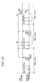
- FIG. 22 shows an example of an access sequence using the present method.
- the base station sequentially transmits Bch, Fch, and RFch from the beginning of a MAC frame.
- a wireless terminal under the base station can recognize a start position of Rch in the frame and the number of slot by receiving RFch.
- the wireless terminal transmits bandwidth request information (RREQ) to request a bandwidth for data transmission to the base station using Rch.
- RREQ bandwidth request information
- the wireless terminal voluntarily determines a back off time, which is a transmission deferred time, based on an exponential back off algorithm in order to avoid collision with other wireless terminals.
- the wireless terminal transmits RREQ using the Rch immediately when the back off time is completed (MAC Frame 1 in FIG. 22 ).
- the wireless terminal retransmits RREQ.
- the base station correctly receives RREQ, the base station notifies of successful RREQ reception using RFch of a next frame (MAC Frame 2 in FIG. 22 ), and assigns Dch according to a bandwidth request value from RREQ. Further, in the next frame (MAC Frame 3 in FIG. 22 ) assigned Dch, the base station assigns Cch for ARQ to inform the wireless terminal of data acknowledgement.
- Non-Patent Document 1 is known as such a conventional art.
- Non-Patent Document 1 Development of 5 GHz bandwidth advanced wireless access (AWA) system-MAC/DCL function-2000 IEICE Society Conference B-5-39 pp.327.
- AWA 5 GHz bandwidth advanced wireless access
- the invention has been achieved in view of the above circumstances, and it is an object of the present invention to provide a wireless communication method, base station apparatus and wireless communication system that allow a wireless terminal device to transmit a bandwidth request message to request a bandwidth used for a given event such as an event with an immediacy requirement to a base station apparatus with a short delay time.
- the wireless terminal device can transmit a bandwidth request message to request a bandwidth used for a given event such as an event with an immediacy requirement to the base station apparatus with a short delay time.
- 1 base station, 2-1 to 2-N: wireless terminal
- 11 base-station transceiver (base-station transmitter, base-station receiver), 12: base-station frame creating and disassembling unit
- 13 base-station transmission and reception manager
- 14 base-station common-slot manager
- 15 base-station transmission and reception controller
- 16 bandwidth manager
- 21 terminal transceiver
- 22 terminal frame creating and disassembling unit
- 23 terminal transmission and reception manager
- 24 terminal slot manager
- 25 terminal transmission and reception controller
- FIG. 1 is a schematic block diagram showing a wireless communication system according to a first embodiment of the present invention.
- the wireless communication system includes a base station 1, and wireless terminals 2-1 to 2-N (hereinafter, referred to as a wireless terminal 2 as a representative of the wireless terminals).
- the base station is also referred to as a base station apparatus.
- the wireless terminal is also referred to as a wireless terminal device.
- the base station 1 is connected to a wired network 4.
- a server 3 is also connected to the wired network 4.
- the base station 1 can communicate with the server 3 via the wired network 4.
- FIG. 2 is a functional block diagram showing a configuration of the base station 1 according to the first embodiment of the present invention.
- the base station 1 includes a base-station transceiver 11, a base-station frame creating and disassembling unit 12, a base-station transmission and reception manager 13, a base-station common-slot manager 14, a base-station transmission and reception controller 15, and a bandwidth manager 16.
- the base-station transceiver 11 performs data transmission and reception to and from a terminal transceiver 21 of the wireless terminal 2, which will be described below.
- the base-station frame creating and disassembling unit 12 performs decoding using an encryption key. Further, the base-station frame creating and disassembling unit 12 determines whether the received data is correct using cyclic redundancy check (CRC) for a received frame (Protocol Data Unit (PDU)) or not.
- CRC cyclic redundancy check
- PDU Protocol Data Unit
- the base-station transmission and reception manager 13 manages data transmission and reception in the base station.
- the base-station common-slot manager 14 manages PDU of a common slot, which will be described below.
- the base-station transmission and reception controller 15 calculates a data transmission and reception timing.
- the bandwidth manager 16 manages wireless bandwidths used for communication.
- a solid arrow in FIG. 2 indicates a flow of the data and a dotted arrow indicates a flow of a control signal.
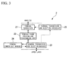
- FIG. 3 is a functional block diagram showing a configuration of the wireless terminal 2 according to the first embodiment of the present invention.
- the wireless terminal 2 includes a terminal transceiver 21, a terminal frame creating and disassembling unit 22, a terminal transmission and reception manager 23, a terminal common-slot manager 24, and a terminal transmission and reception controller 25.
- the terminal transceiver 21 transmits and receives data to and from the base-station transceiver 11 of the base station 1.
- the terminal transmission and reception manager 23 manages data transmission and reception in the wireless terminal 2.
- the terminal common-slot manager 24 specifies a position of a common slot available for transmission from common slot information.
- the terminal transmission and reception manager 25 calculates a transmission timing from the common slot position specified by the terminal common-slot manager 24.
- the frame creating and disassembling unit 22 creates a frame (PDU) from data to transmit.
- a solid arrow indicates a flow of the data and a dotted arrow indicates a flow of a control signal.
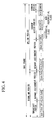
- FIG. 4 shows a configuration of a MAC frame including a common slot in the first embodiment of the present invention.
- the MAC frame is divided into two periods: an uplink and a downlink.
- the downlink period includes a broadcast period and a demand assignment period
- the uplink includes a demand assignment period, a random access period, and a common period.
- Common slots included in the common period are used for the base station 1 to detect occurrence of traffic belonging to a preferential class. A method of detecting the occurrence of traffic will be described below.
- the number of the common slots included in the common period is one or more for one preferential class. In the present embodiment, the preferential class number is 1 and the number of common slot is 1.
- the random access period is divided into Rch belonging to the preferential class and Rch belonging to a non-preferential class.
- the preferential class is a class to which Rch used for an event that is always required to be transmitted with a short delay time (event with an immediacy requirement) belongs.
- the non-preferential class is a class to which Rch other than Rch belonging to the preferential class belongs.
- the base station 1 dynamically changes the ratio between Rch belonging to the preferential class and Rch belonging to the non-preferential class in the random access period according to traffic of an event belonging to the preferential class (an event with an immediacy requirement).
- the method of dynamically changing the ratio will be described below.
- An example of the event with an immediacy requirement includes an event for which the wireless terminal 2 must immediately transmit the information to the base station 1, which is collecting event information. Specifically, an event in which the wireless terminal 2 must immediately transmit abnormality of an object monitored or observed by the wireless terminal 2 to the base station 1 when the object is abnormal is the event with an immediacy requirement.
- Channels such as a broadcast control channel (Bch), a frame control channel (Fch), a random access feedback channel (RFch), a control channel (Cch), a data channel (Dch), and a random access channel (Rch) are used for each period in order to transmit and receive data or control information.
- Bch broadcast control channel
- Fch frame control channel
- RFch random access feedback channel
- Cch control channel
- Dch data channel
- Rch random access channel
- the common period is disposed after the random access period in the present embodiment, a position of the common period is not specified thereto.
- one common slot is disposed for one preferential class, a plurality of common slots may be disposed for the preferential class. Further, the common slot may be distributed in the MAC frame. Further, information on an arrangement of the common slot is broadcasted from the base station 1.
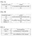
- FIG. 5A shows information elements and the content thereof transmitted using the common slot in the present embodiment.
- the content of the information element "data” is "BIT SEQUENCE PRESCRIBED FOR EACH EVENT”
- the content of the information element "Frame Check Sequence (FCS)” is "CRC (Cyclic Redundancy Check)”.
- FCS is created based on the data.
- the PDU consists of two information elements data and FCS, and the data is identifiable at each event. Further, since FCS is created based on the data, FCS is also common to events. That is, the PDU is common to the events. Further, when the same encryption key is used between the base station 1 and the wireless terminal 2, the encrypted PDU is the same, such that PDU can be encrypted and used.
- the PDU is not specified in the present configuration.
- Terminal information may be included in the information element transmitted using the common slot.
- FIG. 5B shows information elements and the content thereof transmitted using the common slot.
- the content of the information element "data” is "BIT SEQUENCE PRESCRIBED FOR EACH EVENT”
- the content of the information element “FCS (Frame Check Sequence)” is "CRC (Cyclic Redundancy Check)”.
- the FCS is created based on the data.
- the content of the information element "terminal data” is "BIT SEQUENCE PRESCRIBED FOR EACH TERMINAL”
- the content of the information element "terminal FCS (Frame Check Sequence)" is "CRC is used.”
- the terminal FCS is created based on the terminal data.
- the base station 1 receiving "terminal data” via the common slot may recognize a wireless terminal 2 that has transmitted a frame. That is, the base station 1 receiving the frame checks “terminal data" upon CRC, such that the base station 1 can confirm whether “terminal data” is destroyed during transmission or not. When the "terminal data" is destroyed during the transmission, the base station 1 may recognize that a wireless terminal 2 other than the wireless terminal 2 transmitting the frame that has reached the base station 1 is likely to transmit the frame using the same common slot.
- the wireless terminal 2 transmits PDU for a common slot corresponding to the event, which is a transmission object.
- Information on the common slot in a MAC frame (common slot information) is broadcasted from the base station 1 to the wireless terminal 2 using RFch.
- the wireless terminal 2 acquires the common slot information broadcasted by the base station 1, specifies the common slot corresponding to the event, which is a transmission object, and notifies the base station 1 of the occurrence of the event with an immediacy requirement using the specified common slot.
- FIG. 6 shows an event type and slot information of common slot information in the first embodiment of the present invention.
- the slot information of event type "Event 1" is "SLOT INFORMATION 1 (START POSITION)”
- the slot information of event type "event N” is “SLOT INFORMATION N (START POSITION)”.
- the event type is paired with the slot information so that the common slot corresponding to the event can be specified.
- the slot information is able to specify a transmission position, such as a slot start position. Further, when a plurality of common slots are disposed for one event with an immediacy requirement, slot information for the respective common slots is recorded as the slot information. Further, the format of the common slot information is not specified in the present configuration.
- FIG. 7 is a flowchart showing a flow of a transmission process in the wireless terminal 2 in the case where the wireless terminal 2 notifies the base station 1 of an occurrence of an event with an immediacy requirement (hereinafter, referred to as immediate event).
- the terminal transmission and reception manager 23 acquires common slot information based on data that the terminal transceiver 11 receives from the base station 1 (step S101). Subsequently, the terminal transmission and reception manager 23 notifies the terminal common-slot manager 24 of the common slot information.
- the terminal common-slot manager 24 specifies a start position of the common slot corresponding to the immediate event (hereinafter, referred to as a common slot start position) from the common slot information, and notifies the terminal transmission and reception manager 23 of the common slot start position and the immediate event type (step S102).
- the terminal transmission and reception manager 23 notifies the terminal transmission and reception controller 25 of the common slot start position.
- the terminal transmission and reception controller 25 calculates a timing to transmit data notifying of the immediate event occurrence via the common slot.
- the terminal transmission and reception manager 23 also notifies the terminal frame creating and disassembling unit 22 of the immediate event type.
- the terminal frame creating and disassembling unit 22 creates the PDU from the immediate event type and notifies the terminal transceiver 21 of the PDU (step S103).
- the terminal transceiver 21 then transmits the PDU to the base station 1 at a timing indicated by the terminal transmission and reception controller 25 (step S104) and terminates the process.
- FIG. 8 is a flowchart showing a flow of a reception process in the base station 1 in the case where the wireless terminal 2 notifies the base station 1 of the occurrence of the immediate event.
- the base-station transceiver 11 receives data of the common slot based on an indication of the base-station transmission and reception controller 15 (step S201).
- the base-station frame creating and disassembling unit 12 decodes the PDU included in the received common slot using an encryption key when the PDU has been encrypted.
- the base-station frame creating and disassembling unit 12 performs a CRC check on data in the received PDU (step S202). If the CRC check is successful, the process proceeds to step S204, otherwise, the process proceeds to step S208 (step S203).
- step S204 the base-station frame creating and disassembling unit 12 notifies the base-station common-slot manager 14 of the data in the PDU via the base-station transmission and reception manager 13.
- the base-station common-slot manager 14 checks if the notified data is the same as data of an immediate event corresponding to the received common slot (step S204). If the notified data is the same as data of an immediate event corresponding to the received common slot, the process proceeds to step S206, otherwise, the process proceeds to step S208 (step S205).
- the common slot manager 24 determines the PDU as a notification of the occurrence of the immediate event corresponding to the received common slot. The common slot manager 24 then notifies the base-station transmission and reception manager 23 of information indicating that the PDU is the notification of the occurrence of the immediate event corresponding to the received common slot (step S206).
- the common slot manager 24 performs a CRC check on the received terminal information using the terminal FCS. When the CRC check is successful, it is recognized that a single wireless terminal 2 has transmitted data using the common slot, and when the CRC check is not successful, it is recognized that a plurality of wireless terminals 2 have transmitted data using the common slot.
- step S207 the base-station transmission and reception manager 23 initiates control corresponding to the notified immediate event (step S207) and terminates the process.
- the control corresponding to the immediate event corresponds to processing in steps S901 to S903, which will be described below, in the present embodiment.
- step S208 the base-station common-slot manager 24 determines that the PDU is a non-notification of an immediate event corresponding to the received common slot (step S208) and terminates the process.
- the base station 1 can be notified of generation of the traffic belonging to the preferential class (event with an immediacy requirement) from the wireless terminal 2 using the common slot and the PDU. Simultaneously, the base station 1 can recognize which immediate event occurs from the notification.
- the base station 1 dynamically changes the ratio between Rch belonging to the preferential class and Rch belonging to the non-preferential class in the random access period in the present embodiment.
- FIG. 9 is a flowchart showing a procedure by which the base station 1 dynamically changes the ratio between Rch belonging to the preferential class and Rch belonging to the non-preferential class in the random access period in the first embodiment of the present invention.
- Step S901 When there is an access to the common slot, the base-station transmission and reception manager 23 of the base station 1 determines that there is an access to the preferential class corresponding to the accessed common slot. The process then proceeds to step S902.
- Step S902 The base-station transmission and reception manager 23 determines a preferential random access (RA) number of the RA area in a next frame based on a traffic (access) situation determined in step S901 and preferential RA control information. The process then proceeds to step S903.
- RA preferential random access
- Step S903 The base-station transmission and reception manager 23 indicates an accessing method for the accessing wireless terminal 2 belonging to the preferential class based on the number of preferential RA determined in step S902. The process then ends.
- the base station 1 notifies all the wireless terminals 2 connected to the base station 1 of the number of preferential RA determined in step S902 and the accessing method determined in step S903, as preferential RA control information. For example, the base station 1 broadcasts the preferential RA control information to all the wireless terminals 2 connected to the base station 1 using RFch to notify the wireless terminals 2 of the preferential RA control information.
- FIG. 10 shows preferential RA control information in the first embodiment of the present invention.
- the preferential RA control information has attributes such as a preferential class, the number of RA, and an access indication.
- N preferential classes from 1 to N are set. Each class consists of the number of RA that is an assigned the number of slot for the preferential class in RA, and the access indication.
- the access indication has two values.
- the access indication value "0" indicates a method of transmitting RREQ using one frame.
- the access indication value "1" indicates a method of transmitting RREQ using a plurality of frames.
- the number of RA of the preferential class 1 is "2”
- the access indication is "0.”
- the number of RA and the access indications of the other preferential classes are as shown in FIG. 10 .
- the preferential classes included in the preferential RA control information may be recorded in an order of arrangement in an actual RA area.
- the wireless terminal 2 receives RFch and acquires a start position of the RA area and a total number of RA from RFch. Further, the wireless terminal 2 can specify a start slot (position) of an RA area of the class to which the wireless terminal 2 belongs, by using information of all classes present before the RA area of the class to which the wireless terminal 2 belongs from the preferential RA control information.
- the wireless terminal 2 belonging to class 2 recognizes that 8 slots from a third slot (from a third slot to a tenth slot) are in an RA area of the wireless terminal 2 belonging to class 2. Meanwhile, since non-preferential classes exist in an RA area after the preferential classes, the position and the number of slot can be obtained by summing information for all the preferential classes.
- the base station 1 can dynamically change a ratio between Rch belonging to the preferential class and Rch belonging to the non-preferential class in the random access period according to the traffic belonging to the preferential class.
- Step S1101 When traffic (communication) of the preferential class is generated, the wireless terminal 2 notifies the base station 1 of generation of the traffic of the present preferential class using the common slot (processing in steps S101 to S104). The process then proceeds to step S1102. Specifically, the wireless terminal 2 acquires common slot information in RFch, acquires the position and number of the common slot, and notifies the base station 1 of the traffic generation according to a format defined for the common slot.
- Step S1102 The wireless terminal 2 acquires preferential RA control information included in RFch. Further, the wireless terminal 2 performs access control according to the access indication included in the preferential RA control information. The process then proceeds to step S1103.
- Step S1103 The wireless terminal 2 transmits RREQ to a corresponding preferential RA according to the access control performed in step S1102. The process then ends.
- the wireless terminal 2 transmits RREQ according to the above-described procedure.
- a transmission timing at which the wireless terminal 2 transmits RREQ will be described with reference to FIG. 12 .
- FIG. 12 is a sequence diagram showing an RREQ transmission timing in the first embodiment of the present invention.
- a wireless terminal 2 in a preferential class has data (traffic) to transmit
- the wireless terminal 2 transmits a notification to the common slot.
- the wireless terminal 2 acquires common slot information from RFch in frame #N and transmits the notification to the common slot of frame #N.
- the base station 1 determines the number of preferential RA of frame #(N+1) subsequent to frame #N and an accessing method based on the notification result of the common slot of frame #N. Further, the base station 1 broadcasts preferential RA control information including the determined the number of preferential RA and accessing method to the wireless terminal 2, using RFch of frame #(N+1).
- the wireless terminal 2 acquires the preferential RA control information included in RFch of frame #(N+1), performs access control of frame #(N+1) based on the acquired preferential RA control information, and transmits RREQ to the preferential RA of frame #(N+1).
- the base station 1 can assign Rchs to the immediate event by detecting the notification of an occurrence of the immediate event from the wireless terminals 2 and dynamically change the assignment of Rch included in the RA period based on the detected notification. Further, the wireless terminal 2 can transmit RREQ to the base station 1 using the assigned Rchs. Accordingly, the wireless terminal 2 can transmit a bandwidth request message (RREQ), which is a message requesting a bandwidth used for a given event such as an event with an immediacy requirement, to the base station 1 with a short delay time.
- RREQ bandwidth request message
- the first and second concrete examples follow an RREQ transmission sequence described with reference to FIG. 12 .
- the access control of a preferential terminal of the second concrete example is the same as that of the first concrete example.
- the process flow of the wireless terminal 2 described with reference to FIG. 11 of the second concrete example is the same as that of the first concrete example.
- FIG. 13 is a flowchart showing a procedure of determining the number of preferential RA in the base station 1 in the present concrete example.
- the number of common slot for the preferential class is 1. Further, it is assumed that the common slot is received by a reception frame #N.
- Step S1301 The base-station transmission and reception manager 23 determines whether there is an access to the common slot or not. If it is determined that there is an access to the common slot, the process proceeds to step S1302, otherwise, the process proceeds to step S1307. The determination is made using the method shown in steps S201 to S208.
- Step S1302 The base-station transmission and reception manager 23 determines whether the number of the preferential RA in previous frame #(N-1) was 0 or not. If it is determined that the number of the preferential RA was 0, the process proceeds to step S1303 and, otherwise, the process proceeds to step S1304.
- Step S1303 The base-station transmission and reception manager 23 sets the number of preferential RA of the preferential class in frame #(N+1) subsequent to frame #N to an initial value (a defined value). The process then ends.
- Step S1304 Since there was the assignment of the number of preferential RA in frame #(N-1), the base-station transmission and reception manager 23 performs increase processing on the number of preferential RA in frame #(N-1) to calculate the number of preferential RA in frame #(N+1). The process then proceeds to step S1305.
- the number of preferential RA of the frame #(N+1) is equal to the number of preferential RA of frame #(N-1)+ ⁇ (defined value).
- Step S1305) The base-station transmission and reception manager 23 compares the number of preferential RA of the frame #(N+1) calculated in step S1304 with a maximum assignment number (defined value) that can be assigned to the preferential class in one frame. If the number of preferential RA is less than the maximum assignment number, the process ends and, otherwise, the process proceeds to step S1306.
- Step S1306 The base-station transmission and reception manager 23 changes the number of preferential RA of the frame #(N+1) into the maximum assignment number that can be assigned to the preferential class in one frame. The process then ends.
- Step S1307 The base-station transmission and reception manager 23 sets the number of preferential RA of the preferential class in frame #(N+1) to 0. That is, the RA area is not reserved. The process then ends.
- the base station 1 can determine the number of preferential RA. Further, if there are a plurality of common slots for the preferential class, the base station 1 receives all the common slots for the preferential class and then performs processing in steps S1301 to S1307. In this case, it is determined in step S1301 that there is access when there is access in at least one of the plurality of common slots.
- the base-station transmission and reception manager 23 determines the number of preferential RA and then selects, in frame #N, the accessing method for the wireless terminal 2 in the preferential class in #(N+1).
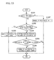
- Step S1401 The base-station transmission and reception manager 23 determines whether the number of preferential RA is equal to the maximum assignment number that can be assigned to the preferential class in one frame or not. If it is determined that the number of preferential RA is equal to the maximum assignment number, the process proceeds to step S1402, otherwise, the process proceeds to step S1403.
- Step S1402 Since the number of preferential RA has reached the maximum assignment number, the base-station transmission and reception manager 23 instructs the wireless terminal 2 to access using a plurality of frames. Accordingly, the base-station transmission and reception manager 23 sets the access indication to "1.” The process then proceeds to step S1404. Further, as the access indication, two types for an odd frame and an even frame for each preferential class are prepared, and a corresponding one of the two types according to the frame number of frame #(N+1) is applied.
- Step S1403 Since the number of preferential RA has not reached the maximum assignment number, the base-station transmission and reception manager 23 instructs the wireless terminal 2 to access using one frame (frame #(N+1)). Accordingly, the base-station transmission and reception manager 23 sets the access indication to "0.” The process then proceeds to step S1404.
- Step S1404 The base-station transmission and reception manager 23 produces preferential RA control information and broadcasts the produced preferential RA control information to the wireless terminal 2 in RFch of frame #(N+1). The process then ends.
- the base station 1 can transmit the preferential RA control information to the wireless terminal 2.
- the wireless terminal 2 transmits RREQ to the base station 1 upon generation of the traffic in the preferential class or upon retransmission.
- a configuration of a frame transmitted using the common slot is the same as in FIG. 5A .
- Step S1501 The wireless terminal 2 acquires common slot information (the number and position of the common slots) for the preferential class from RFch of frame #N. The process then proceeds to step S1502.
- Step S1502 The wireless terminal 2 transmits the notification to the common slot indicated by the common slot information acquired in step S1501 according to a defined format. The process then proceeds to step S1503.
- Step S1503 The wireless terminal 2 receives the preferential RA control information from RFch of frame #(N+1) and acquires an access indication for the preferential class and the number of preferential RA. The process then proceeds to step S1504.
- Step S1504 Since the access indication "0" is an indication of a transmission of RREQ using the present frame, the wireless terminal 2 sets the number of preferential RA to the size of an initial back off window (IBW) and determines a back off number which is uniformly random number to be constant in the number of preferential RA. Further, since the access indication "1" is an indication of a transmission of RREQ using a plurality of frames subsequent to a next frame, the wireless terminal 2 performs increase processing on the IBW size and updates the IBW size. Further, when the access indication is "1" and the back off is initiated, the wireless terminal 2 transmits a notification to the common slot to notify the base station that there is traffic for the preferential RA. The process then proceeds to step S1505.
- IBW initial back off window
- the back off window size is equal to IBW ⁇ 2 when increase processing using power-of-two increase is performed.
- the present embodiment involves a sequence in which the transmission to common slot is first performed to access the preferential RA of a next frame, back off control is initiated at intervals of one frame when the access indication is "1."
- Step S1505 The wireless terminal 2 determines whether the back off number determined in step S1506 is greater than the number of preferential RA of the frame #(N+1) or not. If the back off number is greater than the number of preferential RA of the frame #(N+1), the process proceeds to step S1506 and, otherwise, the process proceeds to step S1507.
- Step S1506 The wireless terminal 2 transmits RREQ using preferential RA of frame #(N+1). The process then ends.
- Step S1507 The wireless terminal 2 transmits RREQ using a preferential RA of the frame #(N+2) and so on. The process then ends.
- the wireless terminal 2 After transmitting RREQ using the preferential RA, the wireless terminal 2 receives RFch of a next frame and determines whether the transmission is successful based on the information included in the received RFch or not. If it is determined that the transmission is successful, the wireless terminal 2 awaits assignment of Dch for data transmission. On the other hand, if it is determined that the transmission is not successful, the wireless terminal 2 again performs processing in steps S1501 to S1507 to retransmit RREQ.
- the base station 1 receives the notification of the occurrence of the immediate event from the wireless terminal 2 and dynamically changes the assignment of Rchs included in the RA period based on the received notification, such that enough Rchs can be assigned to the immediate event. Further, the wireless terminal 2 can transmit RREQ to the base station 1 using the assigned Rchs. Accordingly, the wireless terminal 2 can transmit a bandwidth request message (RREQ), which is a message to request a bandwidth used for a given event such as an event with an immediacy requirement, to the base station 1 with a short delay time.
- RREQ bandwidth request message
- FIG. 16 is a flowchart showing a procedure of determining the number of preferential RA in a base station 1 in the present concrete example.
- processing varies according to three types of accesses: "there is no access to a common slot,” “there is an access to a common slot from one wireless terminal,” and "there is an access to a common slot from two or more wireless terminals" as the result of accessing the common slot.
- the number of common slot for the preferential class is 1.
- the common slot is received by a reception frame #N.
- a configuration of a frame transmitted using the common slot is the same as shown in FIG. 5B .
- Step S1601 The base-station transmission and reception manager 23 determines whether there is an access to the common slot or not. If there is an access to the common slot, the base-station transmission and reception manager 23 also determines how many wireless terminals 2 have access to the common slot. If it is determined that there is no access to the common slot, the process proceeds to step S1602. If it is determined that there is an access to the common slot from one wireless terminal 2, the process proceeds to step S1603. If it is determined that there is an access to the common slot from two or more wireless terminals 2, the process proceeds to step S1604. The determination is made based on the method described in steps S201 to S208.
- Step S1602 The base-station transmission and reception manager 23 sets the number of preferential RA of a preferential class in frame #(N+1) subsequent to frame #N to 0. The process then ends.
- Step S1603 The base-station transmission and reception manager 23 sets the number of preferential RA of the preferential class in frame #(N+1) to 1. The process then ends.
- Step S1604 The base-station transmission and reception manager 23 determines whether the number of the preferential RA in previous frame #(N-1) was 0 or not. If it is determined that the number of the preferential RA was 0, the process proceeds to step S1605, otherwise, the process proceeds to step S1606.
- Step S1605 The base-station transmission and reception manager 23 sets the number of preferential RA of the preferential class in frame #(N+1) subsequent to frame #N to an initial value (a defined value). The process then ends.
- Step S1606 Since there was the assignment of the number of preferential RA in frame #(N-1), the base-station transmission and reception manager 23 performs increase processing on the number of preferential RA in frame #(N-1) to calculate the number of preferential RA in frame #(N+1). The process then proceeds to step S1607.
- the number of preferential RA of the frame #(N+1) is equal to the number of preferential RA of frame #(N-1) + ⁇ (defined value).
- Step S1607 The base-station transmission and reception manager 23 compares the number of preferential RA of frame #(N+1) calculated in step S1606 with a maximum assignment number (a defined value) that can be assigned to the preferential class in one frame. If it is determined that the number of preferential RA is less than the maximum assignment number, the process ends and, otherwise, the process proceeds to step S1608.
- a maximum assignment number a defined value
- Step S1608 The base-station transmission and reception manager 23 changes the number of preferential RA of the frame #(N+1) to the maximum assignment number that can be assigned to the preferential class in one frame. The process then ends.
- a procedure of determining an accessing method for the wireless terminal 2 in the base station 1 and a procedure by which the wireless terminal 2 transmits RREQ to the base station 1 are the same as in the first concrete example.
- the base station 1 receives the notification of the occurrence of the immediate event from the wireless terminal 2 and dynamically changes the assignment of Rchs included in the RA period based on the received notification, such that the base station 1 can assign enough Rchs to the immediate event.
- the wireless terminal 2 can transmit RREQ to the base station 1 using the assigned Rchs.
- the wireless terminal device can transmit a bandwidth request message (RREQ), which is a message to request a bandwidth used for a given event such as an event with an immediacy requirement, to the base station apparatus with a short delay time.
- RREQ bandwidth request message
- the base station 1 When there are a plurality of common slots for the preferential class, the base station 1 receives all the common slots for the preferential class and then performs processing in steps S1601 to S1608. In this case, if it is determined that there is access from two or more wireless terminals 2 in at least one common slot in the notification number determination process, the process proceeds to step S1604 that is a branch to "there is an access to the common slot from two or more wireless terminals.” Otherwise, since the access number can be specified, the number of preferential RA is reserved by the specified access number.
- the wireless terminal 2 since the wireless terminal 2 initially transmits a notification to the common slot to access the preferential RA in a next frame, the preferential RA is accessed at intervals of one frame upon retransmission.
- the following method is used to shorten the time to access the preferential RA by making every frame access to the preferential RA possible.
- the wireless terminal 2 transmits the notification to the common slot in continuationive two frames (frames #N and #(N+1)) upon transmission initiation.
- the wireless terminal 2 transmits RREQ in the preferential RA of frame #(N+1).
- RREQ can be retransmitted to the preferential RA because the notification is transmitted to the common slot in frame #(N+1). Accordingly, there is the assignment of the preferential RA in frame #(N+2), such that RREQ can be retransmitted to the preferential RA. However, since the access to the preferential RA fails in frame #(N+2), the notification is transmitted to the common slot in the present frame for RREQ retransmission.
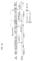
- FIG. 17 shows a simulation result showing a relationship between traffic and a transmission delay time of the preferential class in the case where the wireless communication system according to the first embodiment of the present invention is used.
- the horizontal axis indicates the traffic and the vertical axis indicates a transmission delay time (seconds) of the wireless terminal 2 in the preferential class.
- a graph g21 shows a property when preferential traffic is 0.01 in the case where a wireless communication system according to the first embodiment of the present invention is used.
- a graph g22 shows a property when the preferential traffic is 0.05 in the case where a wireless communication system according to the first embodiment of the present invention is used.
- a graph g11 shows a property when the preferential traffic is 0.01 when a wireless communication system according to conventional art is used.
- a graph g12 shows a property when the preferential traffic is 0.05 when a wireless communication system according to conventional art is used.
- the delay time of the wireless terminal 2 in the preferential class was evaluated as shown in FIG. 17 .
- the delay time is a time taken from generation of data in the wireless terminal 2 to reception of data in the base station 1.
- traffic is normalized to a transmission capacity (9600 bps)
- traffic of a wireless terminal 2 in the non-preferential class is changed with respect to a traffic model having wireless terminals 2 in the two preferential classes of 0.01 and 0.05.
- the data generation in the wireless terminal 2 follows a Poisson distribution (360 seconds in average), and a data length is 320 bits.
- IBW is set to 8 in the preferential class and 32 in the non-preferential class.
- the transmission rate is 9600 bps and the length of frame is 1 second.
- the wireless communication system according to the second embodiment includes a base station 1 and a wireless terminal 2, as in the first embodiment. Description of similarities between the second embodiment and the first embodiment will be omitted.
- FIG. 18 shows a configuration of a MAC frame including a common access slot in the second embodiment of the present invention.
- the MAC frame configuration ( FIG. 18 ) according to the second embodiment is substantially the same as the MAC frame configuration ( FIG. 4 ) according to the first embodiment.
- the first embodiment and the second embodiment differ in that the MAC frame in the former has one common slot while the MAC frame in the latter has two common slots (a first common slot CS1 and a second common slot CS2).
- the MAC frame in the second embodiment has two common slots, it is not limited thereto and the MAC frame may have three or more common slots.
- the terminal transmission and reception manager 23 acquires common slot information based on data that the terminal transceiver 21 receives from the base station 1. Subsequently, the terminal transmission and reception manager 23 notifies the terminal common-slot manager 24 of the common slot information.
- the terminal common-slot manager 24 specifies respective start positions of two common slots (common slots CS1 and CS2 in FIG. 18 ) corresponding to the immediate event based on the common slot information, and notifies the terminal transmission and reception manager 23 of the start positions of the two common slots.
- the terminal transmission and reception manager 23 notifies the terminal transmission and reception controller 25 of the start positions of the two common slots.
- the terminal transmission and reception controller 25 calculates a data transmission timing to notify of the occurrence of the immediate event from the start positions of the common slots corresponding to a transmission history.
- the wireless terminal 2 uses the common slot CS1 for a new notification (see FIG. 18 ).
- the common slot CS2 for retransmission (see FIG. 18 ) is used.
- the base station 1 can identify a transmission history of the wireless terminal 2.
- the common slot CS1 when the common slot CS1 is used for the new notification, the common slot CS2 next to CS1 is used for the retransmission.
- the common slot CS2 may be used for the new notification and the common slot CS1 may be used for the retransmission.
- the terminal transmission and reception manager 23 notifies the terminal frame creating and disassembling unit 22 of the type of the immediate event.
- the terminal frame creating and disassembling unit 22 creates PDU from the type of the immediate event and notifies the terminal transceiver 21 of PDU. Subsequently, the terminal transceiver 21 transmits PDU to the base station 1 at a timing indicated by the terminal transmission and reception controller 25, and terminates the process.
- a reception process for the two common slots CS1 and CS2 is performed in the reception process in the base station 1.
- the base station 1 performs the process of FIG. 8 described in the first embodiment.
- it is determined as "an event notification” in step S206 of FIG. 8 in the first embodiment it is determined as "a new notification of an event” in step S206 of FIG. 8 in the second embodiment.
- it is determined as “an event non-notification” in step S208 of FIG. 8 in the first embodiment it is determined that "there is no new notification of an event” in step S208 of FIG. 8 in the second embodiment.
- the base station 1 performs the process of FIG. 8 described in the first embodiment. However, while it is determined as “an event notification” in step S206 of FIG. 8 in the first embodiment, it is determined as "a retransmission notification of event” in step S206 of FIG. 8 in the second embodiment. While it is determined as an "event non-notification” in step S208 of FIG. 8 in the first embodiment, it is determined that "there is no retransmission notification of an event" in step S208 of FIG. 8 in the second embodiment.
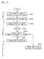
- FIG. 19 is a flowchart showing a procedure of determining the number of preferential RA in the base station 1 in the second embodiment of the present invention.
- the base station 1 determines the number of preferential RA of a next frame #N+1 in a process of receiving a common slot in frame #N.
- the base station 1 detects a retransmission notification irrespective of whether there is a new notification in the reception process or not (step S1201)
- the base station 1 increases the number of preferential RA assigned to frame #N+1 than the number of preferential RA assigned to frame #N-1 (step S1205).
- the base station 1 checks whether the number of preferential RA of the frame #N+1 is smaller than a maximum assignment number or not (step S1206).
- the maximum assignment number is a maximum number of RA that can be assigned to frame #N+1.
- the process of the flowchart in FIG. 19 ends.
- the base station 1 assigns the number of preferential RA equal to the maximum assignment number to frame #N+1 (step S1207).
- step S1202 when the base station 1 does not detect the retransmission notification in step S1201 and does not detect the new notification (step S1202), the base station 1 sets the number of preferential RA assigned to frame #N+1 to 0 (step S1203). That is, the base station 1 does not assign the preferential RA to frame #N+1.
- step S1203 when the base station 1 detects the new notification in step S1202, the base station 1 assigns the number of preferential RA equal to a previously determined initial value to frame #N+1 (step S1204).
- the base station 1 assigns the number of preferential RA equal to the previously determined initial value to frame #N+1 in step S1204 of FIG. 19 , the present invention is not limited thereto.
- the base station 1 may check whether there has been the assignment of the preferential RA in frame #N-1 or not. In the case where there has been the assignment of the preferential RA in frame #N-1, the number of RA equal to the number of RA assigned to frame #N-1 may be assigned to frame #N+1. In the case where there has been no assignment of the preferential RA in frame #N-1, the base station 1 may assign the number of preferential RA equal to the previously determined initial value to frame #N+1.
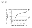
- FIG. 20 is a simulation result showing a relationship between traffic of the wireless terminal 2 in the non-preferential class and a delay time of the wireless terminal 2 in the preferential class in the case where the second embodiment of the present invention is used.
- the horizontal axis indicates the traffic of the wireless terminal 2 in the non-preferential class and the vertical axis indicates the delay time (seconds) of the wireless terminal 2 in the preferential class.
- a graph g31 shows a property in the case where a wireless communication system according to the second embodiment of the present invention is used. Further, a graph g41 shows a property in the case where a wireless communication system according to conventional art is used.
- the delay time of the wireless terminal 2 in the preferential class was evaluated to obtain the simulation result shown in FIG. 20 .
- the delay time is a time taken from data generation in the wireless terminal 2 to data reception in the base station 1.
- the delay time of the wireless terminal 2 in the preferential class is defined as 10 seconds. Further, the delay time of the wireless terminal 2 in the non-preferential class is not defined.
- the traffic of the wireless terminal 2 in the preferential class is fixed (to 0.2) and traffic of the wireless terminal 2 in the non-preferential class is changed.
- the data generation follows a Poisson distribution (333.3 seconds in average), and a data length is 320 bits.
- a transmission capacity is normalized to 9600 bits.
- IBW is 8 in the preferential class and 1024 in the non-preferential class.
- the transmission rate is 9600 bps and the length of frame is 1 second.
- the delay time of the wireless terminal in the preferential class increases, as shown in the graph g41 of FIG. 20 .
- the delay time of the wireless terminal 2 in the preferential class is constant irrespective of the traffic of the wireless terminal 2 in the non-preferential class, it is clear that the transmission quality of the wireless terminal 2 in the preferential class can be guaranteed.
- the present invention is applied to a wireless communication method, a base station apparatus and a wireless communication system in which a wireless terminal device transmits a bandwidth request message for a given event such as event with an immediacy requirement to a base station apparatus with a short delay time.
Abstract
Description
- The present invention relates to a wireless communication method, a base station apparatus and a wireless communication system capable of dynamic bandwidth assignment.
This application claims priority to and the benefit of Japanese Patent Applications No.2008-046016 filed on February 27, 2008 - In recent years, ubiquitous networks using a wireless local and personal areas communication system such as wireless tags, Bluetooth (registered trademark), and ZigBee (registered trademark) have begun to be widely used in the fields of equipment control, traffic, distribution, environmental protection, food industry, agriculture, earthquake monitoring, health care and so on. With the development of applications or services, the number of users of a network is expected to increase in the future. Here, a global ubiquitous network capable of providing several applications or services to a greater number of users and enlarging a service area has been featured.
- In such a situation, a network includes a base station connected to a fixed network, and a number of wireless terminals scattered in a wide area. The wireless terminals are directly accommodated in the base station. Further, the wireless terminals in such a network are driven by a battery and are low-power and low-performance terminals having only a minimum number of functions such as data measurement and transmission. Traffic from such wireless terminals to the base station is characterized by (1) a small amount of data and (2) a relatively long transmission interval.
- Since a number of such wireless terminals are under one base station, traffic properties have a tendency of a great amount of uplink traffic and an increase of a total amount of traffic. In the network, one base station must accommodate as many wireless terminals as possible in order to collect data from the number of wireless terminals as many as possible. Accordingly, such a network needs a media access control (MAC) protocol capable of achieving high throughput and realizing a short transmission delay time while one base station efficiently accommodates a great number of low-performance wireless terminals.
- To satisfy the requirement, a dynamic slot assignment (DSA) method that is a centralized control method is employed as a MAC protocol due to high resource utilization efficiency. The method uses a time division multiple access-time division duplex (TDMA-TDD) as an access scheme. In this method, a base station dynamically assigns slots (bandwidths) according to a request from a wireless terminal.
-
FIG. 21 shows an example of a configuration of a MAC frame. The MAC frame is divided into two periods: an uplink and a downlink. The downlink period consists of a broadcast period and a demand assignment period, and the uplink consists of a demand assignment period and a random access period. - Channels such as a broadcast control channel (Bch), a frame control channel (Fch), a random access feedback channel (RFch), a control channel (Cch), a data channel (Dch), and a random access channel (Rch) are used in each period in order to transmit and receive data or control information.
- Bch is used to inform a wireless terminal of attribute information (e.g., a base station ID and a frame number) of a base station. Fch is used to notify bandwidth assignment information (e.g., a wireless terminal assigned, start point of the assignment, a channel type, and bandwidth amount) of a demand assignment period in which the bandwidth assignment is performed in units of wireless terminal.
- RFch is used to notify of random access information (e.g., a random access result of a previous frame, a start position of random access in the present frame, and the number of slot). Cch is used to transmit and receive control information for each wireless terminal, such as a bandwidth request (resource request, RREQ) or automatic repeat request (ARQ). Dch is used to transmit and receive user data. Rch is a channel for random access and is used for the wireless terminal to transmit the bandwidth request (RREQ).
- In a DSA method, a random access is mainly employed for a wireless terminal to request a bandwidth because it can accommodate aperiodic, bursty data flexibly and efficiently.
FIG. 22 shows an example of an access sequence using the present method. In this example, the base station sequentially transmits Bch, Fch, and RFch from the beginning of a MAC frame. A wireless terminal under the base station can recognize a start position of Rch in the frame and the number of slot by receiving RFch. When the wireless terminal has data to transmit, the wireless terminal transmits bandwidth request information (RREQ) to request a bandwidth for data transmission to the base station using Rch. In this case, the wireless terminal voluntarily determines a back off time, which is a transmission deferred time, based on an exponential back off algorithm in order to avoid collision with other wireless terminals. - The wireless terminal transmits RREQ using the Rch immediately when the back off time is completed (
MAC Frame 1 inFIG. 22 ). When there is a collision with Rch from another wireless terminal, the wireless terminal retransmits RREQ. When the base station correctly receives RREQ, the base station notifies of successful RREQ reception using RFch of a next frame (MAC Frame 2 inFIG. 22 ), and assigns Dch according to a bandwidth request value from RREQ. Further, in the next frame (MAC Frame 3 inFIG. 22 ) assigned Dch, the base station assigns Cch for ARQ to inform the wireless terminal of data acknowledgement. Non-PatentDocument 1 is known as such a conventional art. - However, in the dynamic slot assignment method using the random access, particularly, when there are a number of wireless terminals under a base station, Rch is highly likely to collide with another Rch, which causes overhead. The overhead is the transmission deferred time caused by the exponential back off algorithm, which deteriorates a throughput characteristic. Accordingly, when a bandwidth request message for a bandwidth used for the event with an immediacy requirement is transmitted from the wireless terminal to the base station, it is difficult to transmit the bandwidth request message with a short delay time.
- Now, we assume that a preferential class is requested to be the transmission with a short delay time. Further, to guarantee the preferential class, there is another method which sets the initial back off window (IBW) size of a preferential class to a smaller value rather than that of a non-preferential class. However, since the method uses a random access area for two classes, it is difficult to always guarantee the transmission of the preferential class regardless of the traffic in the non-preferential class. However, since effects of traffic in the non-preferential class cannot be ignored, it is difficult to always guarantee a transmission with a short delay time for the preferential class.
Non-Patent Document 1: Development of 5 GHz bandwidth advanced wireless access (AWA) system-MAC/DCL function-2000 IEICE Society Conference B-5-39 pp.327. - The invention has been achieved in view of the above circumstances, and it is an object of the present invention to provide a wireless communication method, base station apparatus and wireless communication system that allow a wireless terminal device to transmit a bandwidth request message to request a bandwidth used for a given event such as an event with an immediacy requirement to a base station apparatus with a short delay time.
-
- (1) The present invention provides a wireless communication method in which a plurality of wireless terminal devices are connected to a base station apparatus via a common wireless line, the base station apparatus managing an assignable period for wireless terminal in an uplink communication period of a wireless frame as a demand assignment period and a remaining period as a random access period, and assigning a requested uplink communication bandwidth according to bandwidth request information from the wireless terminal device, and the wireless terminal device transmitting the bandwidth request information using a random slot in the random access period when data to transmit is generated, and transmitting the data using the bandwidth assigned to an uplink demand assignment period form the base station apparatus when the bandwidth request information is successfully transmitted, wherein the wireless frame further includes a common slot for transmitting information notifying of an occurrence of a given event, and the method includes: transmitting, by the wireless terminal device, information indicating the occurrence of the given event in the wireless terminal device to the base station apparatus using the common slot; determining, by the base station apparatus, the number of random slots assigned as random slots to transmit the bandwidth request information for the given event among random slots in the random access period, based on the occurrence of the given event transmitted in the transmission of the information indicating the occurrence of the given event; transmitting, by the base station apparatus, information on the assigned random slots to the wireless terminal device of random access period; and transmitting, by the wireless terminal device, the bandwidth request information to the base station apparatus using the random slots assigned in the determination based on the information on the assigned random slots transmitted by the transmission of the information on the assigned random slots.
-
- (2) In the wireless communication method of the present invention, when the occurrence of a given event is notified in the transmission of the information indicating the occurrence of the given event, the base station apparatus may change the number of the random slots assigned to the wireless terminal device.
-
- (3) In the wireless communication method of the present invention, the base station apparatus may change the number of random slots assigned as random slots to the wireless terminal device, based on whether the information indicating the occurrence of the given event transmitted from the wireless terminal device in the transmission of the information indicating the occurrence of the given event is being retransmitted or not.
-
- (4) In the wireless communication method of the present invention, the common slots may have a first common slot and a second common slot, and in the transmission of the information indicating the occurrence of the given event, the wireless terminal device: may transmit the information indicating the occurrence of the given event using the first common slot when the information indicating the occurrence of the given event is not being retransmitted to the base station apparatus; and may transmit the information indicating the occurrence of the given event using the second slot when the information indicating the occurrence of the given event is being retransmitted to the base station apparatus.
-
- (5) The present invention provides a base station apparatus which connects a plurality of wireless terminal devices via a common wireless line, managing an assignable period for wireless terminal in an uplink communication period of a wireless frame as a demand assignment period and a remaining period as a random access period, and assigning a requested uplink communication bandwidth according to bandwidth request information from the wireless terminal device, wherein the wireless frame further includes a common slot for transmitting information notifying of an occurrence of a given event, and the base station apparatus includes: a base-station receiver which receives information indicating the occurrence of the given event in the wireless terminal device, the information being transmitted from the wireless terminal device using the common slot; a base-station transmission and reception manager which determines the number of random slots assigned as random slots to transmit the bandwidth request information for the given event among random slots in the random access period, based on the occurrence of the given event received by the base-station receiver; and a base-station transmitter which transmits, in the base station apparatus, information on the assigned random slots to the wireless terminal device of random access period.
-
- (6) In the base station apparatus of the present invention, when the base-station receiver detects the occurrence of the given event from the wireless terminal device, the base-station transmission and reception manager may change the number of random slots assigned to the wireless terminal device.
-
- (7) In the base station apparatus of the present invention, the base-station transmission and reception manager may change the number of random slots assigned as random slots to the wireless terminal device based on whether the information indicating the occurrence of the given event transmitted from the wireless terminal device and received by the base-station receiver is being retransmitted or not.
-
- (8) The present invention provides a wireless communication system in which a plurality of wireless terminal devices are connected to a base station apparatus via a common wireless line, the base station apparatus managing an assignable period for wireless terminal in an uplink communication period of a wireless frame as a demand assignment period and a remaining period as a random access period, and assigning a requested uplink communication bandwidth according to bandwidth request information from the wireless terminal device, and the wireless terminal device transmitting the bandwidth request information using a random slot in the random access period when data to transmit is generated, and transmitting the data using the bandwidth assigned to an uplink demand assignment period form the base station apparatus when the bandwidth request information is successfully transmitted, wherein the wireless frame further includes a common slot for transmitting information notifying of an occurrence of a given event, the wireless terminal device includes: an event occurrence notification unit which transmits information indicating the occurrence of the given event in the wireless terminal device to the base station apparatus using the common slot; and a bandwidth requesting unit which transmits the bandwidth request information to the base station apparatus using random slots based on random slot assignment information transmitted from the base station apparatus, and the base station apparatus includes: a base-station receiver which receives information indicating the occurrence of the given event in the wireless terminal device, the information being transmitted from the wireless terminal device using the common slot; a base-station transmission and reception manager which determines the number of random slots assigned as random slots to transmit the bandwidth request information for the given event among random slots in the random access period, based on the occurrence of the given event received by the base-station receiver; and a base-station transmitter which transmits, in the base station apparatus, information on the assigned random slots to the wireless terminal device of random access period.
-
- (9) In the wireless communication system of the present invention, when the base-station receiver detects occurrence of a given event from the wireless terminal device, the base-station transmission and reception manager may change the number of the random slots assigned to the wireless terminal device.
-
- (10) In the wireless communication system of the present invention, the base-station transmission and reception manager may change the number of random slots assigned as random slots to the wireless terminal device based on whether the information indicating the occurrence of the given event transmitted from the wireless terminal device and received by the base-station receiver is being retransmitted or not.
-
- (11) In the wireless communication system of the present invention, the common slots have a first common slot and a second common slot, and the event occurrence notification unit: transmits the information indicating the occurrence of the given event using the first common slot when the information indicating the occurrence of the given event is not retransmitted to the base station apparatus; and transmits the information indicating the occurrence of the given event using the second slot when the information indicating the occurrence of the given event is being retransmitted to the base station apparatus.
- According to the present invention, the wireless terminal device can transmit a bandwidth request message to request a bandwidth used for a given event such as an event with an immediacy requirement to the base station apparatus with a short delay time.
-
-
FIG. 1 is a schematic block diagram showing a wireless communication system according to a first embodiment of the present invention. -
FIG. 2 is a functional block diagram showing a configuration of abase station 1 according to the first embodiment of the present invention. -
FIG. 3 is a functional block diagram showing a configuration of awireless terminal 2 according to the first embodiment of the present invention. -
FIG. 4 shows a configuration of a MAC frame including a common access slot in the first embodiment of the present invention. -
FIG. 5A shows information elements and the content thereof transmitted using a common slot in the present embodiment. -
FIG. 5B shows information elements and the content thereof transmitted in the common slot in the present embodiment. -
FIG. 6 shows an event type and slot information of common slot information in the first embodiment of the present invention. -
FIG. 7 is a flowchart showing a flow of a transmission process in thewireless terminal 2 in the first embodiment of the present invention. -
FIG. 8 is a flowchart showing a flow of a reception process in thebase station 1 in the first embodiment of the present invention. -
FIG. 9 is a flowchart showing a procedure by which thebase station 1 dynamically changes the ratio between Rch belonging to a preferential class and Rch belonging to a non-preferential class in a random access period in the first embodiment of the present invention. -
FIG. 10 shows preferential RA control information in the first embodiment of the present invention. -
FIG. 11 is a flowchart showing a procedure by which awireless terminal 2 transmits RREQ in the first embodiment of the present invention. -
FIG. 12 is a sequence diagram showing an RREQ transmission timing in the first exemplary of the present invention. -
FIG. 13 is a flowchart showing a procedure of determining the number of preferential RA in thebase station 1 in a first concrete example. -
FIG. 14 is a flowchart showing a procedure by which thebase station 1 determines an accessing method for awireless terminal 2 in the first concrete example. -
FIG. 15 is a flowchart showing a procedure by which thewireless terminal 2 transmits RREQ to thebase station 1 in the first concrete example. -
FIG. 16 is a flowchart showing a procedure of determining the number of preferential RA in abase station 1 in a second concrete example. -
FIG. 17 shows a simulation result showing a relationship between traffic and a transmission delay time of a preferential class in the case where the wireless communication system according to the first embodiment of the present invention is used. -
FIG. 18 shows a configuration of a MAC frame including a common access slot in a second embodiment of the present invention. -
FIG. 19 is a flowchart showing a procedure of determining the number of preferential RA in thebase station 1 in the second embodiment of the present invention. -
FIG. 20 is a simulation result showing a relationship between traffic of awireless terminal 2 in a non-preferential class and a delay time of awireless terminal 2 in a preferential class in the case where the second embodiment of the present invention is used. -
FIG. 21 shows an example of a configuration of a frame in a conventional art. -
FIG. 22 shows an example of an access sequence in a conventional art. - 1: base station, 2-1 to 2-N: wireless terminal, 11: base-station transceiver (base-station transmitter, base-station receiver), 12: base-station frame creating and disassembling unit, 13: base-station transmission and reception manager, 14: base-station common-slot manager, 15: base-station transmission and reception controller, 16: bandwidth manager, 21: terminal transceiver, 22: terminal frame creating and disassembling unit, 23: terminal transmission and reception manager, 24: terminal slot manager, 25: terminal transmission and reception controller
- Hereinafter, respective embodiments of the present invention will be described with reference to the accompanying drawings. First, a first embodiment of the present invention will be described.
-
FIG. 1 is a schematic block diagram showing a wireless communication system according to a first embodiment of the present invention. The wireless communication system includes abase station 1, and wireless terminals 2-1 to 2-N (hereinafter, referred to as awireless terminal 2 as a representative of the wireless terminals). The base station is also referred to as a base station apparatus. The wireless terminal is also referred to as a wireless terminal device. Thebase station 1 is connected to awired network 4. Aserver 3 is also connected to thewired network 4. Thebase station 1 can communicate with theserver 3 via thewired network 4. - Next, a configuration of the
base station 1 of the present embodiment will be described.FIG. 2 is a functional block diagram showing a configuration of thebase station 1 according to the first embodiment of the present invention. Thebase station 1 includes a base-station transceiver 11, a base-station frame creating and disassemblingunit 12, a base-station transmission andreception manager 13, a base-station common-slot manager 14, a base-station transmission andreception controller 15, and abandwidth manager 16. - The base-
station transceiver 11 performs data transmission and reception to and from aterminal transceiver 21 of thewireless terminal 2, which will be described below. Where data received by the base-station transceiver 11 has been encrypted, the base-station frame creating and disassemblingunit 12 performs decoding using an encryption key. Further, the base-station frame creating and disassemblingunit 12 determines whether the received data is correct using cyclic redundancy check (CRC) for a received frame (Protocol Data Unit (PDU)) or not. The base-station transmission andreception manager 13 manages data transmission and reception in the base station. The base-station common-slot manager 14 manages PDU of a common slot, which will be described below. The base-station transmission andreception controller 15 calculates a data transmission and reception timing. Thebandwidth manager 16 manages wireless bandwidths used for communication. In addition, a solid arrow inFIG. 2 indicates a flow of the data and a dotted arrow indicates a flow of a control signal. - Next, a configuration of the
wireless terminal 2 of the present embodiment will be described.FIG. 3 is a functional block diagram showing a configuration of thewireless terminal 2 according to the first embodiment of the present invention. Thewireless terminal 2 includes aterminal transceiver 21, a terminal frame creating and disassemblingunit 22, a terminal transmission andreception manager 23, a terminal common-slot manager 24, and a terminal transmission andreception controller 25. - The
terminal transceiver 21 transmits and receives data to and from the base-station transceiver 11 of thebase station 1. The terminal transmission andreception manager 23 manages data transmission and reception in thewireless terminal 2. The terminal common-slot manager 24 specifies a position of a common slot available for transmission from common slot information. The terminal transmission andreception manager 25 calculates a transmission timing from the common slot position specified by the terminal common-slot manager 24. The frame creating and disassemblingunit 22 creates a frame (PDU) from data to transmit. InFIG. 3 , a solid arrow indicates a flow of the data and a dotted arrow indicates a flow of a control signal. - Next, a configuration of a MAC frame of the present embodiment will be described.
FIG. 4 shows a configuration of a MAC frame including a common slot in the first embodiment of the present invention. The MAC frame is divided into two periods: an uplink and a downlink. The downlink period includes a broadcast period and a demand assignment period, and the uplink includes a demand assignment period, a random access period, and a common period. - Common slots included in the common period are used for the
base station 1 to detect occurrence of traffic belonging to a preferential class. A method of detecting the occurrence of traffic will be described below. The number of the common slots included in the common period is one or more for one preferential class. In the present embodiment, the preferential class number is 1 and the number of common slot is 1. - In the present embodiment, the random access period is divided into Rch belonging to the preferential class and Rch belonging to a non-preferential class. The preferential class is a class to which Rch used for an event that is always required to be transmitted with a short delay time (event with an immediacy requirement) belongs. The non-preferential class is a class to which Rch other than Rch belonging to the preferential class belongs.
- The
base station 1 dynamically changes the ratio between Rch belonging to the preferential class and Rch belonging to the non-preferential class in the random access period according to traffic of an event belonging to the preferential class (an event with an immediacy requirement). The method of dynamically changing the ratio will be described below. - An example of the event with an immediacy requirement includes an event for which the
wireless terminal 2 must immediately transmit the information to thebase station 1, which is collecting event information. Specifically, an event in which thewireless terminal 2 must immediately transmit abnormality of an object monitored or observed by thewireless terminal 2 to thebase station 1 when the object is abnormal is the event with an immediacy requirement. - Channels such as a broadcast control channel (Bch), a frame control channel (Fch), a random access feedback channel (RFch), a control channel (Cch), a data channel (Dch), and a random access channel (Rch) are used for each period in order to transmit and receive data or control information.
- Although the common period is disposed after the random access period in the present embodiment, a position of the common period is not specified thereto. Further, although one common slot is disposed for one preferential class, a plurality of common slots may be disposed for the preferential class. Further, the common slot may be distributed in the MAC frame. Further, information on an arrangement of the common slot is broadcasted from the
base station 1. - Hereinafter, a method by which the
base station 1 detects occurrence of traffic belonging to the preferential class (event with an immediacy requirement) in the present embodiment will be described. - A configuration of a frame (Protocol Data Unit (PDU)) transmitted using a common slot in the present embodiment will be described.
FIG. 5A shows information elements and the content thereof transmitted using the common slot in the present embodiment. In the shown example, which has two lines, the content of the information element "data" is "BIT SEQUENCE PRESCRIBED FOR EACH EVENT", and the content of the information element "Frame Check Sequence (FCS)" is "CRC (Cyclic Redundancy Check)". FCS is created based on the data. In the present embodiment, the PDU consists of two information elements data and FCS, and the data is identifiable at each event. Further, since FCS is created based on the data, FCS is also common to events. That is, the PDU is common to the events. Further, when the same encryption key is used between thebase station 1 and thewireless terminal 2, the encrypted PDU is the same, such that PDU can be encrypted and used. The PDU is not specified in the present configuration. - Terminal information may be included in the information element transmitted using the common slot.
FIG. 5B shows information elements and the content thereof transmitted using the common slot. In a shown example, which has four lines, the content of the information element "data" is "BIT SEQUENCE PRESCRIBED FOR EACH EVENT", and the content of the information element "FCS (Frame Check Sequence)" is "CRC (Cyclic Redundancy Check)". The FCS is created based on the data. The content of the information element "terminal data" is "BIT SEQUENCE PRESCRIBED FOR EACH TERMINAL", and the content of the information element "terminal FCS (Frame Check Sequence)" is "CRC is used." The terminal FCS is created based on the terminal data. Where "terminal data" is included as the information element, thebase station 1 receiving "terminal data" via the common slot may recognize awireless terminal 2 that has transmitted a frame. That is, thebase station 1 receiving the frame checks "terminal data" upon CRC, such that thebase station 1 can confirm whether "terminal data" is destroyed during transmission or not. When the "terminal data" is destroyed during the transmission, thebase station 1 may recognize that awireless terminal 2 other than thewireless terminal 2 transmitting the frame that has reached thebase station 1 is likely to transmit the frame using the same common slot. - Next, a notifying method by which the
wireless terminal 2 notifies thebase station 1 of an occurrence of an event with an immediacy requirement using the common slot and the PDU will be described. When thewireless terminal 2 notifies thebase station 1 of the occurrence of the event with an immediacy requirement, thewireless terminal 2 transmits PDU for a common slot corresponding to the event, which is a transmission object. Information on the common slot in a MAC frame (common slot information) is broadcasted from thebase station 1 to thewireless terminal 2 using RFch. Thewireless terminal 2 acquires the common slot information broadcasted by thebase station 1, specifies the common slot corresponding to the event, which is a transmission object, and notifies thebase station 1 of the occurrence of the event with an immediacy requirement using the specified common slot. -
FIG. 6 shows an event type and slot information of common slot information in the first embodiment of the present invention. In a shown example, which has N lines, the slot information of event type "Event 1" is "SLOT INFORMATION 1 (START POSITION)", and the slot information of event type "event N" is "SLOT INFORMATION N (START POSITION)". The event type is paired with the slot information so that the common slot corresponding to the event can be specified. The slot information is able to specify a transmission position, such as a slot start position. Further, when a plurality of common slots are disposed for one event with an immediacy requirement, slot information for the respective common slots is recorded as the slot information. Further, the format of the common slot information is not specified in the present configuration. -
FIG. 7 is a flowchart showing a flow of a transmission process in thewireless terminal 2 in the case where thewireless terminal 2 notifies thebase station 1 of an occurrence of an event with an immediacy requirement (hereinafter, referred to as immediate event). In thewireless terminal 2 synchronized to a MAC frame that performs transmission and reception, the terminal transmission andreception manager 23 acquires common slot information based on data that theterminal transceiver 11 receives from the base station 1 (step S101). Subsequently, the terminal transmission andreception manager 23 notifies the terminal common-slot manager 24 of the common slot information. The terminal common-slot manager 24 specifies a start position of the common slot corresponding to the immediate event (hereinafter, referred to as a common slot start position) from the common slot information, and notifies the terminal transmission andreception manager 23 of the common slot start position and the immediate event type (step S102). - Subsequently, the terminal transmission and
reception manager 23 notifies the terminal transmission andreception controller 25 of the common slot start position. The terminal transmission andreception controller 25 calculates a timing to transmit data notifying of the immediate event occurrence via the common slot. The terminal transmission andreception manager 23 also notifies the terminal frame creating and disassemblingunit 22 of the immediate event type. The terminal frame creating and disassemblingunit 22 creates the PDU from the immediate event type and notifies theterminal transceiver 21 of the PDU (step S103). Theterminal transceiver 21 then transmits the PDU to thebase station 1 at a timing indicated by the terminal transmission and reception controller 25 (step S104) and terminates the process. -
FIG. 8 is a flowchart showing a flow of a reception process in thebase station 1 in the case where thewireless terminal 2 notifies thebase station 1 of the occurrence of the immediate event. In thebase station 1, the base-station transceiver 11 receives data of the common slot based on an indication of the base-station transmission and reception controller 15 (step S201). The base-station frame creating and disassemblingunit 12 decodes the PDU included in the received common slot using an encryption key when the PDU has been encrypted. The base-station frame creating and disassemblingunit 12 performs a CRC check on data in the received PDU (step S202). If the CRC check is successful, the process proceeds to step S204, otherwise, the process proceeds to step S208 (step S203). - In step S204, the base-station frame creating and disassembling
unit 12 notifies the base-station common-slot manager 14 of the data in the PDU via the base-station transmission andreception manager 13. The base-station common-slot manager 14 checks if the notified data is the same as data of an immediate event corresponding to the received common slot (step S204). If the notified data is the same as data of an immediate event corresponding to the received common slot, the process proceeds to step S206, otherwise, the process proceeds to step S208 (step S205). - In step S206, the
common slot manager 24 determines the PDU as a notification of the occurrence of the immediate event corresponding to the received common slot. Thecommon slot manager 24 then notifies the base-station transmission andreception manager 23 of information indicating that the PDU is the notification of the occurrence of the immediate event corresponding to the received common slot (step S206). In addition, when the terminal information is included in the information element transmitted using the common slot, thecommon slot manager 24 performs a CRC check on the received terminal information using the terminal FCS. When the CRC check is successful, it is recognized that asingle wireless terminal 2 has transmitted data using the common slot, and when the CRC check is not successful, it is recognized that a plurality ofwireless terminals 2 have transmitted data using the common slot. - In step S207, the base-station transmission and
reception manager 23 initiates control corresponding to the notified immediate event (step S207) and terminates the process. The control corresponding to the immediate event corresponds to processing in steps S901 to S903, which will be described below, in the present embodiment. - In step S208, the base-station common-
slot manager 24 determines that the PDU is a non-notification of an immediate event corresponding to the received common slot (step S208) and terminates the process. - Thus, the
base station 1 can be notified of generation of the traffic belonging to the preferential class (event with an immediacy requirement) from thewireless terminal 2 using the common slot and the PDU. Simultaneously, thebase station 1 can recognize which immediate event occurs from the notification. - Hereinafter, a method by which the
base station 1 dynamically changes the ratio between Rch belonging to the preferential class and Rch belonging to the non-preferential class in the random access period in the present embodiment will be described. -
FIG. 9 is a flowchart showing a procedure by which thebase station 1 dynamically changes the ratio between Rch belonging to the preferential class and Rch belonging to the non-preferential class in the random access period in the first embodiment of the present invention. - (Step S901) When there is an access to the common slot, the base-station transmission and
reception manager 23 of thebase station 1 determines that there is an access to the preferential class corresponding to the accessed common slot. The process then proceeds to step S902. - (Step S902) The base-station transmission and
reception manager 23 determines a preferential random access (RA) number of the RA area in a next frame based on a traffic (access) situation determined in step S901 and preferential RA control information. The process then proceeds to step S903. A method of determining the number of preferential RA will be described in first and second concrete examples below. - (Step S903) The base-station transmission and
reception manager 23 indicates an accessing method for the accessingwireless terminal 2 belonging to the preferential class based on the number of preferential RA determined in step S902. The process then ends. In the present embodiment, there are two accessing methods: a method of transmitting RREQ using one frame and a method of transmitting RREQ using a plurality of frames. - The
base station 1 notifies all thewireless terminals 2 connected to thebase station 1 of the number of preferential RA determined in step S902 and the accessing method determined in step S903, as preferential RA control information. For example, thebase station 1 broadcasts the preferential RA control information to all thewireless terminals 2 connected to thebase station 1 using RFch to notify thewireless terminals 2 of the preferential RA control information. - Next, preferential RA control information will be described.
FIG. 10 shows preferential RA control information in the first embodiment of the present invention. The preferential RA control information has attributes such as a preferential class, the number of RA, and an access indication. In a shown example, N preferential classes from 1 to N are set. Each class consists of the number of RA that is an assigned the number of slot for the preferential class in RA, and the access indication. - The access indication has two values. The access indication value "0" indicates a method of transmitting RREQ using one frame. The access indication value "1" indicates a method of transmitting RREQ using a plurality of frames. In the shown example, the number of RA of the
preferential class 1 is "2," and the access indication is "0." The number of RA and the access indications of the other preferential classes are as shown inFIG. 10 . - The preferential classes included in the preferential RA control information may be recorded in an order of arrangement in an actual RA area. In this case, the
wireless terminal 2 receives RFch and acquires a start position of the RA area and a total number of RA from RFch. Further, thewireless terminal 2 can specify a start slot (position) of an RA area of the class to which thewireless terminal 2 belongs, by using information of all classes present before the RA area of the class to which thewireless terminal 2 belongs from the preferential RA control information. - For example, in
FIG. 10 , since the number of slot ofclass 1 is 2, thewireless terminal 2 belonging toclass 2 recognizes that 8 slots from a third slot (from a third slot to a tenth slot) are in an RA area of thewireless terminal 2 belonging toclass 2. Meanwhile, since non-preferential classes exist in an RA area after the preferential classes, the position and the number of slot can be obtained by summing information for all the preferential classes. - Thus, the
base station 1 can dynamically change a ratio between Rch belonging to the preferential class and Rch belonging to the non-preferential class in the random access period according to the traffic belonging to the preferential class. - Hereinafter, a procedure by which the
wireless terminal 2 transmits RREQ in the present embodiment will be described with reference toFIG. 11 . - (Step S1101) When traffic (communication) of the preferential class is generated, the
wireless terminal 2 notifies thebase station 1 of generation of the traffic of the present preferential class using the common slot (processing in steps S101 to S104). The process then proceeds to step S1102. Specifically, thewireless terminal 2 acquires common slot information in RFch, acquires the position and number of the common slot, and notifies thebase station 1 of the traffic generation according to a format defined for the common slot. - (Step S1102) The
wireless terminal 2 acquires preferential RA control information included in RFch. Further, thewireless terminal 2 performs access control according to the access indication included in the preferential RA control information. The process then proceeds to step S1103. - (Step S1103) The
wireless terminal 2 transmits RREQ to a corresponding preferential RA according to the access control performed in step S1102. The process then ends. - The
wireless terminal 2 transmits RREQ according to the above-described procedure. In this case, a transmission timing at which thewireless terminal 2 transmits RREQ will be described with reference toFIG. 12 . -
FIG. 12 is a sequence diagram showing an RREQ transmission timing in the first embodiment of the present invention. Where awireless terminal 2 in a preferential class has data (traffic) to transmit, thewireless terminal 2 transmits a notification to the common slot. In an example shown inFIG. 12 , thewireless terminal 2 acquires common slot information from RFch in frame #N and transmits the notification to the common slot of frame #N. - The
base station 1 determines the number of preferential RA of frame #(N+1) subsequent to frame #N and an accessing method based on the notification result of the common slot of frame #N. Further, thebase station 1 broadcasts preferential RA control information including the determined the number of preferential RA and accessing method to thewireless terminal 2, using RFch of frame #(N+1). - The
wireless terminal 2 acquires the preferential RA control information included in RFch of frame #(N+1), performs access control of frame #(N+1) based on the acquired preferential RA control information, and transmits RREQ to the preferential RA of frame #(N+1). - As described above, according to the first embodiment of the present invention, the
base station 1 can assign Rchs to the immediate event by detecting the notification of an occurrence of the immediate event from thewireless terminals 2 and dynamically change the assignment of Rch included in the RA period based on the detected notification. Further, thewireless terminal 2 can transmit RREQ to thebase station 1 using the assigned Rchs. Accordingly, thewireless terminal 2 can transmit a bandwidth request message (RREQ), which is a message requesting a bandwidth used for a given event such as an event with an immediacy requirement, to thebase station 1 with a short delay time. - Next, a method of determining the number of preferential RA will be described using the first and second concrete examples. The first and second concrete examples follow an RREQ transmission sequence described with reference to
FIG. 12 . In addition, there is a difference in a format of the common slot between the first concrete example and the second concrete example. This yields a difference in a method of determining traffic of the preferential class and a method of controlling the number of preferential RA in a process flow in thebase station 1. The access control of a preferential terminal of the second concrete example is the same as that of the first concrete example. The process flow of thewireless terminal 2 described with reference toFIG. 11 of the second concrete example is the same as that of the first concrete example. - A method of determining the number of preferential RA in the first concrete example will be described with reference to
FIG. 13. FIG. 13 is a flowchart showing a procedure of determining the number of preferential RA in thebase station 1 in the present concrete example. In the present concrete example, the number of common slot for the preferential class is 1. Further, it is assumed that the common slot is received by a reception frame #N. - (Step S1301) The base-station transmission and
reception manager 23 determines whether there is an access to the common slot or not. If it is determined that there is an access to the common slot, the process proceeds to step S1302, otherwise, the process proceeds to step S1307. The determination is made using the method shown in steps S201 to S208. - (Step S1302) The base-station transmission and
reception manager 23 determines whether the number of the preferential RA in previous frame #(N-1) was 0 or not. If it is determined that the number of the preferential RA was 0, the process proceeds to step S1303 and, otherwise, the process proceeds to step S1304. - (Step S1303) The base-station transmission and
reception manager 23 sets the number of preferential RA of the preferential class in frame #(N+1) subsequent to frame #N to an initial value (a defined value). The process then ends. - (Step S1304) Since there was the assignment of the number of preferential RA in frame #(N-1), the base-station transmission and
reception manager 23 performs increase processing on the number of preferential RA in frame #(N-1) to calculate the number of preferential RA in frame #(N+1). The process then proceeds to step S1305. - In addition, all increase controls such as exponential growth, power increase, logarithmic increase, and linear increase can be applied as increase processing. For example, in the case of linear increase processing, the number of preferential RA of the frame #(N+1) is equal to the number of preferential RA of frame #(N-1)+α (defined value).
- (Step S1305) The base-station transmission and
reception manager 23 compares the number of preferential RA of the frame #(N+1) calculated in step S1304 with a maximum assignment number (defined value) that can be assigned to the preferential class in one frame. If the number of preferential RA is less than the maximum assignment number, the process ends and, otherwise, the process proceeds to step S1306. - (Step S1306) The base-station transmission and
reception manager 23 changes the number of preferential RA of the frame #(N+1) into the maximum assignment number that can be assigned to the preferential class in one frame. The process then ends. - (Step S1307) The base-station transmission and
reception manager 23 sets the number of preferential RA of the preferential class in frame #(N+1) to 0. That is, the RA area is not reserved. The process then ends. - As described above, the
base station 1 can determine the number of preferential RA. Further, if there are a plurality of common slots for the preferential class, thebase station 1 receives all the common slots for the preferential class and then performs processing in steps S1301 to S1307. In this case, it is determined in step S1301 that there is access when there is access in at least one of the plurality of common slots. - Next, a procedure of determining an accessing method for the
wireless terminal 2 in thebase station 1 in the first concrete example will be described with reference toFIG. 14 . The base-station transmission andreception manager 23 determines the number of preferential RA and then selects, in frame #N, the accessing method for thewireless terminal 2 in the preferential class in #(N+1). - (Step S1401) The base-station transmission and
reception manager 23 determines whether the number of preferential RA is equal to the maximum assignment number that can be assigned to the preferential class in one frame or not. If it is determined that the number of preferential RA is equal to the maximum assignment number, the process proceeds to step S1402, otherwise, the process proceeds to step S1403. - (Step S1402) Since the number of preferential RA has reached the maximum assignment number, the base-station transmission and
reception manager 23 instructs thewireless terminal 2 to access using a plurality of frames. Accordingly, the base-station transmission andreception manager 23 sets the access indication to "1." The process then proceeds to step S1404. Further, as the access indication, two types for an odd frame and an even frame for each preferential class are prepared, and a corresponding one of the two types according to the frame number of frame #(N+1) is applied. - (Step S1403) Since the number of preferential RA has not reached the maximum assignment number, the base-station transmission and
reception manager 23 instructs thewireless terminal 2 to access using one frame (frame #(N+1)). Accordingly, the base-station transmission andreception manager 23 sets the access indication to "0." The process then proceeds to step S1404. - (Step S1404) The base-station transmission and
reception manager 23 produces preferential RA control information and broadcasts the produced preferential RA control information to thewireless terminal 2 in RFch of frame #(N+1). The process then ends. - As described above, the
base station 1 can transmit the preferential RA control information to thewireless terminal 2. - Next, a procedure by which the
wireless terminal 2 transmits RREQ to thebase station 1 in the first concrete example will be described with reference toFIG. 15 . Thewireless terminal 2 transmits RREQ to thebase station 1 upon generation of the traffic in the preferential class or upon retransmission. In addition, in the present concrete example, a configuration of a frame transmitted using the common slot is the same as inFIG. 5A . - (Step S1501) The
wireless terminal 2 acquires common slot information (the number and position of the common slots) for the preferential class from RFch of frame #N. The process then proceeds to step S1502. - (Step S1502) The
wireless terminal 2 transmits the notification to the common slot indicated by the common slot information acquired in step S1501 according to a defined format. The process then proceeds to step S1503. - (Step S1503) The
wireless terminal 2 receives the preferential RA control information from RFch of frame #(N+1) and acquires an access indication for the preferential class and the number of preferential RA. The process then proceeds to step S1504. - (Step S1504) Since the access indication "0" is an indication of a transmission of RREQ using the present frame, the
wireless terminal 2 sets the number of preferential RA to the size of an initial back off window (IBW) and determines a back off number which is uniformly random number to be constant in the number of preferential RA. Further, since the access indication "1" is an indication of a transmission of RREQ using a plurality of frames subsequent to a next frame, thewireless terminal 2 performs increase processing on the IBW size and updates the IBW size. Further, when the access indication is "1" and the back off is initiated, thewireless terminal 2 transmits a notification to the common slot to notify the base station that there is traffic for the preferential RA. The process then proceeds to step S1505. - All increase controls such as exponential growth, power increase, logarithmic increase, and linear increase can be applied as increase processing. For example, in the case where an initial value of the IBW size is the maximum assignment number (the number of the preferential RA when the access indications is "1"), the back off window size is equal to IBW ×2 when increase processing using power-of-two increase is performed. As shown in
FIG. 12 , since the present embodiment involves a sequence in which the transmission to common slot is first performed to access the preferential RA of a next frame, back off control is initiated at intervals of one frame when the access indication is "1." - (Step S1505) The
wireless terminal 2 determines whether the back off number determined in step S1506 is greater than the number of preferential RA of the frame #(N+1) or not. If the back off number is greater than the number of preferential RA of the frame #(N+1), the process proceeds to step S1506 and, otherwise, the process proceeds to step S1507. - (Step S1506) The
wireless terminal 2 transmits RREQ using preferential RA of frame #(N+1). The process then ends.
(Step S1507) Thewireless terminal 2 transmits RREQ using a preferential RA of the frame #(N+2) and so on. The process then ends. - After transmitting RREQ using the preferential RA, the
wireless terminal 2 receives RFch of a next frame and determines whether the transmission is successful based on the information included in the received RFch or not. If it is determined that the transmission is successful, thewireless terminal 2 awaits assignment of Dch for data transmission. On the other hand, if it is determined that the transmission is not successful, thewireless terminal 2 again performs processing in steps S1501 to S1507 to retransmit RREQ. - As described above, according to the present concrete example, the
base station 1 receives the notification of the occurrence of the immediate event from thewireless terminal 2 and dynamically changes the assignment of Rchs included in the RA period based on the received notification, such that enough Rchs can be assigned to the immediate event. Further, thewireless terminal 2 can transmit RREQ to thebase station 1 using the assigned Rchs. Accordingly, thewireless terminal 2 can transmit a bandwidth request message (RREQ), which is a message to request a bandwidth used for a given event such as an event with an immediacy requirement, to thebase station 1 with a short delay time. - A method of determining the number of preferential RA in a second concrete example will be described with reference to
FIG. 16. FIG. 16 is a flowchart showing a procedure of determining the number of preferential RA in abase station 1 in the present concrete example. In the present concrete example, processing varies according to three types of accesses: "there is no access to a common slot," "there is an access to a common slot from one wireless terminal," and "there is an access to a common slot from two or more wireless terminals" as the result of accessing the common slot.
In the present concrete example, the number of common slot for the preferential class is 1. Further, it is assumed that the common slot is received by a reception frame #N. In the present concrete example, a configuration of a frame transmitted using the common slot is the same as shown inFIG. 5B . - (Step S1601) The base-station transmission and
reception manager 23 determines whether there is an access to the common slot or not. If there is an access to the common slot, the base-station transmission andreception manager 23 also determines howmany wireless terminals 2 have access to the common slot. If it is determined that there is no access to the common slot, the process proceeds to step S1602. If it is determined that there is an access to the common slot from onewireless terminal 2, the process proceeds to step S1603. If it is determined that there is an access to the common slot from two ormore wireless terminals 2, the process proceeds to step S1604. The determination is made based on the method described in steps S201 to S208. - (Step S1602) The base-station transmission and
reception manager 23 sets the number of preferential RA of a preferential class in frame #(N+1) subsequent to frame #N to 0. The process then ends. - (Step S1603) The base-station transmission and
reception manager 23 sets the number of preferential RA of the preferential class in frame #(N+1) to 1. The process then ends. - (Step S1604) The base-station transmission and
reception manager 23 determines whether the number of the preferential RA in previous frame #(N-1) was 0 or not. If it is determined that the number of the preferential RA was 0, the process proceeds to step S1605, otherwise, the process proceeds to step S1606. - (Step S1605) The base-station transmission and
reception manager 23 sets the number of preferential RA of the preferential class in frame #(N+1) subsequent to frame #N to an initial value (a defined value). The process then ends. - (Step S1606) Since there was the assignment of the number of preferential RA in frame #(N-1), the base-station transmission and
reception manager 23 performs increase processing on the number of preferential RA in frame #(N-1) to calculate the number of preferential RA in frame #(N+1). The process then proceeds to step S1607. - All increase controls such as exponential increase, power increase, logarithmic increase and linear increase can be applied as increase processing. For example, in the case of linear increase processing, the number of preferential RA of the frame #(N+1) is equal to the number of preferential RA of frame #(N-1) + α (defined value).
- (Step S1607) The base-station transmission and
reception manager 23 compares the number of preferential RA of frame #(N+1) calculated in step S1606 with a maximum assignment number (a defined value) that can be assigned to the preferential class in one frame. If it is determined that the number of preferential RA is less than the maximum assignment number, the process ends and, otherwise, the process proceeds to step S1608. - (Step S1608) The base-station transmission and
reception manager 23 changes the number of preferential RA of the frame #(N+1) to the maximum assignment number that can be assigned to the preferential class in one frame. The process then ends. - A procedure of determining an accessing method for the
wireless terminal 2 in thebase station 1 and a procedure by which thewireless terminal 2 transmits RREQ to thebase station 1 are the same as in the first concrete example. - As described above, according to the present concrete example, the
base station 1 receives the notification of the occurrence of the immediate event from thewireless terminal 2 and dynamically changes the assignment of Rchs included in the RA period based on the received notification, such that thebase station 1 can assign enough Rchs to the immediate event. In this case, in the present concrete example, it is possible to determine the number of preferential RA according to the three accesses: "there is no access to the common slot," "there is an access to the common slot from one wireless terminal," and "there is an access to the common slot from two or more wireless terminals." Further, thewireless terminal 2 can transmit RREQ to thebase station 1 using the assigned Rchs. Accordingly, the wireless terminal device can transmit a bandwidth request message (RREQ), which is a message to request a bandwidth used for a given event such as an event with an immediacy requirement, to the base station apparatus with a short delay time. - When there are a plurality of common slots for the preferential class, the
base station 1 receives all the common slots for the preferential class and then performs processing in steps S1601 to S1608. In this case, if it is determined that there is access from two ormore wireless terminals 2 in at least one common slot in the notification number determination process, the process proceeds to step S1604 that is a branch to "there is an access to the common slot from two or more wireless terminals." Otherwise, since the access number can be specified, the number of preferential RA is reserved by the specified access number. - In the present embodiment, in order to control a preferential RA area for each preferential class, even when there are a plurality of preferential classes, it is possible to perform independent control for each preferential class.
- In the present embodiment, since the
wireless terminal 2 initially transmits a notification to the common slot to access the preferential RA in a next frame, the preferential RA is accessed at intervals of one frame upon retransmission. Here, the following method is used to shorten the time to access the preferential RA by making every frame access to the preferential RA possible.
Specifically, thewireless terminal 2 transmits the notification to the common slot in continutive two frames (frames #N and #(N+1)) upon transmission initiation. Thewireless terminal 2 transmits RREQ in the preferential RA of frame #(N+1). If the access to the preferential RA fails (which is detected in frame #(N+2)), RREQ can be retransmitted to the preferential RA because the notification is transmitted to the common slot in frame #(N+1). Accordingly, there is the assignment of the preferential RA in frame #(N+2), such that RREQ can be retransmitted to the preferential RA. However, since the access to the preferential RA fails in frame #(N+2), the notification is transmitted to the common slot in the present frame for RREQ retransmission. - Next, effects in the case where the first embodiment of the present invention is used will be described with reference to
FIG. 17. FIG. 17 shows a simulation result showing a relationship between traffic and a transmission delay time of the preferential class in the case where the wireless communication system according to the first embodiment of the present invention is used. InFIG. 17 , the horizontal axis indicates the traffic and the vertical axis indicates a transmission delay time (seconds) of thewireless terminal 2 in the preferential class. - In
FIG. 17 , a graph g21 shows a property when preferential traffic is 0.01 in the case where a wireless communication system according to the first embodiment of the present invention is used. Further, a graph g22 shows a property when the preferential traffic is 0.05 in the case where a wireless communication system according to the first embodiment of the present invention is used.
Further, a graph g11 shows a property when the preferential traffic is 0.01 when a wireless communication system according to conventional art is used. Further, a graph g12 shows a property when the preferential traffic is 0.05 when a wireless communication system according to conventional art is used. - Where there are two
wireless terminals 2 in the preferential class and the non-preferential class, the delay time of thewireless terminal 2 in the preferential class was evaluated as shown inFIG. 17 . The delay time is a time taken from generation of data in thewireless terminal 2 to reception of data in thebase station 1.
Here, traffic is normalized to a transmission capacity (9600 bps), and traffic of awireless terminal 2 in the non-preferential class is changed with respect to a traffic model havingwireless terminals 2 in the two preferential classes of 0.01 and 0.05. The data generation in thewireless terminal 2 follows a Poisson distribution (360 seconds in average), and a data length is 320 bits.
In the wireless communication system according to conventional art, IBW is set to 8 in the preferential class and 32 in the non-preferential class. Further, as other parameters, the transmission rate is 9600 bps and the length of frame is 1 second. - In a wireless communication system according to conventional art, since a transmission delay time increases with traffic as shown in the graphs g11 and g12 of
FIG. 17 , it is clear that the system cannot provide the low delay transmission.
On the other hand, since the wireless communication system according to the first embodiment of the present invention maintains a constant delay time (4 seconds or less) irrespective of variation of traffic, it is obvious that the system can provide the transmission with a short delay time, as shown in the graphs g21 and g22 ofFIG. 17 . - Next, a wireless communication system according to a second embodiment of the present invention will be described. The wireless communication system according to the second embodiment includes a
base station 1 and awireless terminal 2, as in the first embodiment. Description of similarities between the second embodiment and the first embodiment will be omitted. -
FIG. 18 shows a configuration of a MAC frame including a common access slot in the second embodiment of the present invention. In the second embodiment, two common slots are assigned to awireless terminal 2 in a preferential class. Accordingly, the MAC frame configuration (FIG. 18 ) according to the second embodiment is substantially the same as the MAC frame configuration (FIG. 4 ) according to the first embodiment. However, the first embodiment and the second embodiment differ in that the MAC frame in the former has one common slot while the MAC frame in the latter has two common slots (a first common slot CS1 and a second common slot CS2). Although the MAC frame in the second embodiment has two common slots, it is not limited thereto and the MAC frame may have three or more common slots. - Next, a flow of a transmission process in the
wireless terminal 2 in the case where thewireless terminal 2 notifies thebase station 1 of an occurrence of an event with an immediacy requirement (hereinafter, referred to as immediate event) will be described.
In thewireless terminal 2 synchronized with the MAC frame that performs transmission and reception, the terminal transmission andreception manager 23 acquires common slot information based on data that theterminal transceiver 21 receives from thebase station 1. Subsequently, the terminal transmission andreception manager 23 notifies the terminal common-slot manager 24 of the common slot information. The terminal common-slot manager 24 specifies respective start positions of two common slots (common slots CS1 and CS2 inFIG. 18 ) corresponding to the immediate event based on the common slot information, and notifies the terminal transmission andreception manager 23 of the start positions of the two common slots. - Subsequently, the terminal transmission and
reception manager 23 notifies the terminal transmission andreception controller 25 of the start positions of the two common slots. The terminal transmission andreception controller 25 calculates a data transmission timing to notify of the occurrence of the immediate event from the start positions of the common slots corresponding to a transmission history. Here, when thewireless terminal 2 notifies of a new immediate event, thewireless terminal 2 uses the common slot CS1 for a new notification (seeFIG. 18 ). Meanwhile, when the immediate event notification is retransmitted, the common slot CS2 for retransmission (seeFIG. 18 ) is used. Accordingly, it is possible to identify whether the immediate event notification is a new notification or a retransmitted notification from thewireless terminal 2 based on which of the common slot CS1 and the common slot CS2 is used to transmit the immediate event notification from thewireless terminal 2. That is, thebase station 1 can identify a transmission history of thewireless terminal 2.
InFIG. 18 , when the common slot CS1 is used for the new notification, the common slot CS2 next to CS1 is used for the retransmission. Alternatively, the common slot CS2 may be used for the new notification and the common slot CS1 may be used for the retransmission. - The terminal transmission and
reception manager 23 notifies the terminal frame creating and disassemblingunit 22 of the type of the immediate event. The terminal frame creating and disassemblingunit 22 creates PDU from the type of the immediate event and notifies theterminal transceiver 21 of PDU. Subsequently, theterminal transceiver 21 transmits PDU to thebase station 1 at a timing indicated by the terminal transmission andreception controller 25, and terminates the process. - Meanwhile, a reception process for the two common slots CS1 and CS2 is performed in the reception process in the
base station 1.
For the common slot CS1 for a new notification, thebase station 1 performs the process ofFIG. 8 described in the first embodiment. However, while it is determined as "an event notification" in step S206 ofFIG. 8 in the first embodiment, it is determined as "a new notification of an event" in step S206 ofFIG. 8 in the second embodiment.
Further, while it is determined as "an event non-notification" in step S208 ofFIG. 8 in the first embodiment, it is determined that "there is no new notification of an event" in step S208 ofFIG. 8 in the second embodiment. - For the retransmission common slot CS2, the
base station 1 performs the process ofFIG. 8 described in the first embodiment. However, while it is determined as "an event notification" in step S206 ofFIG. 8 in the first embodiment, it is determined as "a retransmission notification of event" in step S206 ofFIG. 8 in the second embodiment.
While it is determined as an "event non-notification" in step S208 ofFIG. 8 in the first embodiment, it is determined that "there is no retransmission notification of an event" in step S208 ofFIG. 8 in the second embodiment. -
FIG. 19 is a flowchart showing a procedure of determining the number of preferential RA in thebase station 1 in the second embodiment of the present invention. In the second embodiment, thebase station 1 determines the number of preferential RA of a next frame #N+1 in a process of receiving a common slot in frame #N.
Initially, when thebase station 1 detects a retransmission notification irrespective of whether there is a new notification in the reception process or not (step S1201), thebase station 1 increases the number of preferential RA assigned to frame #N+1 than the number of preferential RA assigned to frame #N-1 (step S1205). - When the
base station 1 performs processing in step S1205, thebase station 1 checks whether the number of preferential RA of the frame #N+1 is smaller than a maximum assignment number or not (step S1206). Here, the maximum assignment number is a maximum number of RA that can be assigned to frame #N+1.
When the number of preferential RA is smaller than the maximum assignment number in step S1206, the process of the flowchart inFIG. 19 ends. On the other hand, when the number of preferential RA is equal to or greater than the maximum assignment number in step S1206, thebase station 1 assigns the number of preferential RA equal to the maximum assignment number to frame #N+1 (step S1207). - Meanwhile, when the
base station 1 does not detect the retransmission notification in step S1201 and does not detect the new notification (step S1202), thebase station 1 sets the number of preferential RA assigned to frame #N+1 to 0 (step S1203). That is, thebase station 1 does not assign the preferential RA to frame #N+1.
On the other hand, when thebase station 1 detects the new notification in step S1202, thebase station 1 assigns the number of preferential RA equal to a previously determined initial value to frame #N+1 (step S1204). - Although the
base station 1 assigns the number of preferential RA equal to the previously determined initial value to frame #N+1 in step S1204 ofFIG. 19 , the present invention is not limited thereto.
For example, thebase station 1 may check whether there has been the assignment of the preferential RA in frame #N-1 or not. In the case where there has been the assignment of the preferential RA in frame #N-1, the number of RA equal to the number of RA assigned to frame #N-1 may be assigned to frame #N+1. In the case where there has been no assignment of the preferential RA in frame #N-1, thebase station 1 may assign the number of preferential RA equal to the previously determined initial value to frame #N+1. - Next, effects when the second embodiment of the present invention is used will be described with reference to
FIG. 20. FIG. 20 is a simulation result showing a relationship between traffic of thewireless terminal 2 in the non-preferential class and a delay time of thewireless terminal 2 in the preferential class in the case where the second embodiment of the present invention is used. InFIG. 20 , the horizontal axis indicates the traffic of thewireless terminal 2 in the non-preferential class and the vertical axis indicates the delay time (seconds) of thewireless terminal 2 in the preferential class. - In
FIG. 20 , a graph g31 shows a property in the case where a wireless communication system according to the second embodiment of the present invention is used.
Further, a graph g41 shows a property in the case where a wireless communication system according to conventional art is used. - Where there are two wireless terminals, which are a
wireless terminal 2 in the preferential class and awireless terminal 2 in the non-preferential class, the delay time of thewireless terminal 2 in the preferential class was evaluated to obtain the simulation result shown inFIG. 20 . The delay time is a time taken from data generation in thewireless terminal 2 to data reception in thebase station 1.
In the simulation, the delay time of thewireless terminal 2 in the preferential class is defined as 10 seconds. Further, the delay time of thewireless terminal 2 in the non-preferential class is not defined. - The traffic of the
wireless terminal 2 in the preferential class is fixed (to 0.2) and traffic of thewireless terminal 2 in the non-preferential class is changed.
In this traffic model, the data generation follows a Poisson distribution (333.3 seconds in average), and a data length is 320 bits. For the traffic, a transmission capacity is normalized to 9600 bits.
In a wireless communication system according to conventional art, IBW is 8 in the preferential class and 1024 in the non-preferential class. As other parameters, the transmission rate is 9600 bps and the length of frame is 1 second. - In the wireless communication system according to conventional art, as the traffic of the wireless terminal in the non-preferential class increases, the delay time of the wireless terminal in the preferential class increases, as shown in the graph g41 of
FIG. 20 . This means that a transmission quality of the wireless terminal in the preferential class cannot be guaranteed.
On the other end, in the wireless communication system according to the second embodiment of the present invention, since the delay time of thewireless terminal 2 in the preferential class is constant irrespective of the traffic of thewireless terminal 2 in the non-preferential class, it is clear that the transmission quality of thewireless terminal 2 in the preferential class can be guaranteed. - Although the embodiments of the present invention have been described in detail with reference to the accompanying drawings, a detailed configurations are not limited thereto. That is, various modifications can be made to the above-described embodiments of the present invention without departing from the scope of the invention.
- The present invention is applied to a wireless communication method, a base station apparatus and a wireless communication system in which a wireless terminal device transmits a bandwidth request message for a given event such as event with an immediacy requirement to a base station apparatus with a short delay time.
Claims (11)
- A wireless communication method in which a plurality of wireless terminal devices are connected to a base station apparatus via a common wireless line, the base station apparatus managing an assignable period for wireless terminal in an uplink communication period of a wireless frame as a demand assignment period and a remaining period as a random access period, and assigning a requested uplink communication bandwidth according to bandwidth request information from the wireless terminal device, and the wireless terminal device transmitting the bandwidth request information using a random slot in the random access period when data to transmit is generated, and transmitting the data using the bandwidth assigned to an uplink demand assignment period from the base station apparatus when the bandwidth request information is successfully transmitted,
wherein the wireless frame further comprises a common slot for transmitting information notifying of an occurrence of a given event, and
the method comprises:transmitting, by the wireless terminal device, information indicating the occurrence of the given event in the wireless terminal device to the base station apparatus using the common slot;determining, by the base station apparatus, the number of random slots assigned as random slots to transmit the bandwidth request information for the given event among random slots in the random access period, based on the occurrence of the given event transmitted in the transmission of the information indicating the occurrence of the given event;transmitting, by the base station apparatus, information on the assigned random slots to the wireless terminal device of random access period; andtransmitting, by the wireless terminal device, the bandwidth request information to the base station apparatus using the random slots assigned in the determination based on the information on the assigned random slots transmitted by the transmission of the information on the assigned random slots. - The wireless communication method according to claim 1, wherein when the occurrence of a given event is notified in the transmission of the information indicating the occurrence of the given event, the base station apparatus changes the number of the random slots assigned to the wireless terminal device.
- The wireless communication method according to claim 1, wherein the base station apparatus changes the number of random slots assigned as random slots to the wireless terminal device, based on whether the information indicating the occurrence of the given event transmitted from the wireless terminal device in the transmission of the information indicating the occurrence of the given event is being retransmitted or not.
- The wireless communication method according to claim 3, wherein the common slots have a first common slot and a second common slot, and
in the transmission of the information indicating the occurrence of the given event, the wireless terminal device:transmits the information indicating the occurrence of the given event using the first common slot when the information indicating the occurrence of the given event is not being retransmitted to the base station apparatus; andtransmits the information indicating the occurrence of the given event using the second slot when the information indicating the occurrence of the given event is being retransmitted to the base station apparatus. - A base station apparatus which connects a plurality of wireless terminal devices via a common wireless line, managing an assignable period for wireless terminal in an uplink communication period of a wireless frame as a demand assignment period and a remaining period as a random access period, and assigning a requested uplink communication bandwidth according to bandwidth request information from the wireless terminal device,
wherein the wireless frame further comprises a common slot for transmitting information notifying of an occurrence of a given event, and
the base station apparatus comprises:a base-station receiver which receives information indicating the occurrence of the given event in the wireless terminal device, the information being transmitted from the wireless terminal device using the common slot;a base-station transmission and reception manager which determines the number of random slots assigned as random slots to transmit the bandwidth request information for the given event among random slots in the random access period, based on the occurrence of the given event received by the base-station receiver; anda base-station transmitter which transmits, in the base station apparatus, information on the assigned random slots to the wireless terminal device of random access period. - The base station apparatus according to claim 5, wherein when the base-station receiver detects the occurrence of the given event from the wireless terminal device, the base-station transmission and reception manager changes the number of random slots assigned to the wireless terminal device.
- The base station apparatus according to claim 5, wherein the base-station transmission and reception manager changes the number of random slots assigned as random slots to the wireless terminal device based on whether the information indicating the occurrence of the given event transmitted from the wireless terminal device and received by the base-station receiver is being retransmitted or not.
- A wireless communication system in which a plurality of wireless terminal devices are connected to a base station apparatus via a common wireless line, the base station apparatus managing an assignable period for wireless terminal in an uplink communication period of a wireless frame as a demand assignment period and a remaining period as a random access period, and assigning a requested uplink communication bandwidth according to bandwidth request information from the wireless terminal device, and the wireless terminal device transmitting the bandwidth request information using a random slot in the random access period when data to transmit is generated, and transmitting the data using the bandwidth assigned to an uplink demand assignment period form the base station apparatus when the bandwidth request information is successfully transmitted,
wherein the wireless frame further comprises a common slot for transmitting information notifying of an occurrence of a given event,
the wireless terminal device comprises:an event occurrence notification unit which transmits information indicating the occurrence of the given event in the wireless terminal device to the base station apparatus using the common slot; anda bandwidth requesting unit which transmits the bandwidth request information to the base station apparatus using random slots based on random slot assignment information transmitted from the base station apparatus, andthe base station apparatus comprises:a base-station receiver which receives information indicating the occurrence of the given event in the wireless terminal device, the information being transmitted from the wireless terminal device using the common slot;
a base-station transmission and reception manager which determines the number of random slots assigned as random slots to transmit the bandwidth request information for the given event among random slots in the random access period, based on the occurrence of the given event received by the base-station receiver; and
a base-station transmitter which transmits, in the base station apparatus, information on the assigned random slots to the wireless terminal device of random access period. - The wireless communication system according to claim 8, wherein when the base-station receiver detects occurrence of a given event from the wireless terminal device, the base-station transmission and reception manager changes the number of the random slots assigned to the wireless terminal device.
- The wireless communication system according to claim 8, wherein the base-station transmission and reception manager changes the number of random slots assigned as random slots to the wireless terminal device based on whether the information indicating the occurrence of the given event transmitted from the wireless terminal device and received by the base-station receiver is being retransmitted or not.
- The wireless communication system according to claim 10, wherein the common slots have a first common slot and a second common slot, and
the event occurrence notification unit:transmits the information indicating the occurrence of the given event using the first common slot when the information indicating the occurrence of the given event is not retransmitted to the base station apparatus; andtransmits the information indicating the occurrence of the given event using the second slot when the information indicating the occurrence of the given event is being retransmitted to the base station apparatus.
Applications Claiming Priority (2)
| Application Number | Priority Date | Filing Date | Title |
|---|---|---|---|
| JP2008046016 | 2008-02-27 | ||
| PCT/JP2009/050364 WO2009107413A1 (en) | 2008-02-27 | 2009-01-14 | Wireless communication method, base station, and wireless communication system |
Publications (3)
| Publication Number | Publication Date |
|---|---|
| EP2249613A1 true EP2249613A1 (en) | 2010-11-10 |
| EP2249613A4 EP2249613A4 (en) | 2016-03-23 |
| EP2249613B1 EP2249613B1 (en) | 2017-10-25 |
Family
ID=41015819
Family Applications (1)
| Application Number | Title | Priority Date | Filing Date |
|---|---|---|---|
| EP09713899.4A Active EP2249613B1 (en) | 2008-02-27 | 2009-01-14 | Wireless communication method, base station, and wireless communication system |
Country Status (5)
| Country | Link |
|---|---|
| US (1) | US8660098B2 (en) |
| EP (1) | EP2249613B1 (en) |
| JP (1) | JP4987118B2 (en) |
| CN (1) | CN101946552B (en) |
| WO (1) | WO2009107413A1 (en) |
Cited By (2)
| Publication number | Priority date | Publication date | Assignee | Title |
|---|---|---|---|---|
| WO2014010945A1 (en) * | 2012-07-10 | 2014-01-16 | 한국전자통신연구원 | Method and apparatus for allocating flexible transmission slot in wireless lan system |
| US11184847B2 (en) | 2012-07-10 | 2021-11-23 | Electronics And Telecommunications Research Institute | Method and apparatus for allocating flexible transmission slot in wireless LAN system |
Families Citing this family (13)
| Publication number | Priority date | Publication date | Assignee | Title |
|---|---|---|---|---|
| JP5303749B2 (en) * | 2010-04-06 | 2013-10-02 | 日本電信電話株式会社 | Wireless communication method and base station apparatus |
| CN102291846B (en) * | 2010-06-21 | 2016-01-20 | 中兴通讯股份有限公司 | A kind of accidental access method and realize the system of Stochastic accessing |
| GB201114079D0 (en) * | 2011-06-13 | 2011-09-28 | Neul Ltd | Mobile base station |
| JP2013005293A (en) * | 2011-06-17 | 2013-01-07 | Toshiba Corp | Authentication component, authentication target component, and authentication method for the same |
| US9468024B2 (en) * | 2011-06-30 | 2016-10-11 | Lg Electronics Inc. | Method and apparatus for ranging transmission by mobile station in wireless communication system |
| JP5650146B2 (en) * | 2012-02-22 | 2015-01-07 | 日本電信電話株式会社 | Wireless communication system and access control method |
| US9532301B2 (en) * | 2013-09-26 | 2016-12-27 | Qualcomm Incorporated | On-demand, request-response based discovery in peer-to-peer networks |
| WO2016050281A1 (en) * | 2014-09-30 | 2016-04-07 | Nokia Solutions And Networks Oy | Method and apparatus for tracking idle devices |
| CN104469966B (en) * | 2014-12-08 | 2019-03-01 | 哈尔滨工业大学深圳研究生院 | Accidental access method and system of the TD-LTE virtual Private Network based on dynamic priority |
| US9980284B2 (en) * | 2015-03-13 | 2018-05-22 | Huawei Technologies Co., Ltd. | Contention-based reservations of network resources |
| US10334631B2 (en) * | 2016-05-27 | 2019-06-25 | Huawei Technologies Canada Co., Ltd. | System and method for a configurable frame structure |
| CN112399547B (en) * | 2019-08-14 | 2022-07-05 | 深圳长城开发科技股份有限公司 | Method for improving LoRa downlink real-time performance, LoRa gateway, LoRa terminal and storage medium |
| US11757526B1 (en) * | 2020-06-01 | 2023-09-12 | Space Exploration Technologies Corp. | Initial network entry to a communications system |
Family Cites Families (14)
| Publication number | Priority date | Publication date | Assignee | Title |
|---|---|---|---|---|
| US5742594A (en) | 1996-06-13 | 1998-04-21 | Motorola, Inc. | Method and apparatus for allocating shared bandwidth among a plurality of users |
| DE69834639T2 (en) * | 1998-10-05 | 2006-12-14 | Sony Deutschland Gmbh | Automatic determination of the point for random access channel splitting method |
| DE69940933D1 (en) * | 1998-10-05 | 2009-07-09 | Sony Deutschland Gmbh | Direct access burst transmission with at least one message part |
| EP2088830B1 (en) * | 1998-10-05 | 2015-04-08 | Sony Deutschland GmbH | Random access channel prioritization scheme |
| JP3698946B2 (en) * | 2000-02-28 | 2005-09-21 | 三菱電機株式会社 | Wireless random access control method |
| US6353617B1 (en) | 2000-04-11 | 2002-03-05 | Motorola, Inc. | Method for accessing a communication medium |
| JP4022625B2 (en) * | 2004-03-08 | 2007-12-19 | 独立行政法人情報通信研究機構 | Communication system, communication method, base station, and mobile station |
| WO2006082616A1 (en) * | 2005-01-31 | 2006-08-10 | Fujitsu Limited | Wireless communication system, and base station and terminals used in that system |
| CN100515115C (en) | 2005-10-14 | 2009-07-15 | 华为技术有限公司 | Bandwidth competition method for WiMax system |
| JP4550013B2 (en) | 2006-06-08 | 2010-09-22 | 日本電信電話株式会社 | Wireless communication method, dynamic bandwidth allocation method, wireless communication system, and base station |
| US7804799B2 (en) * | 2006-12-29 | 2010-09-28 | Intel Corporation | Uplink contention based access with quick access channel |
| EP1954087A1 (en) * | 2007-02-05 | 2008-08-06 | Nokia Siemens Networks Gmbh & Co. Kg | Method for reducing collisions and apparatus thereof |
| US7881340B2 (en) * | 2007-10-22 | 2011-02-01 | The Johns Hopkins University | Decentralized media access control for ad-hoc mobile wireless network |
| KR101519345B1 (en) * | 2008-01-01 | 2015-05-21 | 주식회사 팬택 | A method for transmitting and receiving random access request and transmitting and receiving random access response |
-
2009
- 2009-01-14 EP EP09713899.4A patent/EP2249613B1/en active Active
- 2009-01-14 US US12/918,217 patent/US8660098B2/en active Active
- 2009-01-14 WO PCT/JP2009/050364 patent/WO2009107413A1/en active Application Filing
- 2009-01-14 JP JP2010500603A patent/JP4987118B2/en active Active
- 2009-01-14 CN CN200980105526.3A patent/CN101946552B/en active Active
Non-Patent Citations (1)
| Title |
|---|
| See references of WO2009107413A1 * |
Cited By (3)
| Publication number | Priority date | Publication date | Assignee | Title |
|---|---|---|---|---|
| WO2014010945A1 (en) * | 2012-07-10 | 2014-01-16 | 한국전자통신연구원 | Method and apparatus for allocating flexible transmission slot in wireless lan system |
| US11184847B2 (en) | 2012-07-10 | 2021-11-23 | Electronics And Telecommunications Research Institute | Method and apparatus for allocating flexible transmission slot in wireless LAN system |
| US11729715B2 (en) | 2012-07-10 | 2023-08-15 | Electronics And Telecommunications Research Institute | Method and apparatus for allocating flexible transmission slot in wireless LAN system |
Also Published As
| Publication number | Publication date |
|---|---|
| WO2009107413A1 (en) | 2009-09-03 |
| EP2249613B1 (en) | 2017-10-25 |
| US8660098B2 (en) | 2014-02-25 |
| CN101946552B (en) | 2016-06-15 |
| JPWO2009107413A1 (en) | 2011-06-30 |
| JP4987118B2 (en) | 2012-07-25 |
| US20110007720A1 (en) | 2011-01-13 |
| EP2249613A4 (en) | 2016-03-23 |
| CN101946552A (en) | 2011-01-12 |
Similar Documents
| Publication | Publication Date | Title |
|---|---|---|
| EP2249613B1 (en) | Wireless communication method, base station, and wireless communication system | |
| US11770867B2 (en) | Association establishment method and apparatus | |
| JP5185367B2 (en) | Wireless communication method, wireless communication system, base station, and terminal station | |
| KR102602946B1 (en) | System information window management method for sending and receiving system information | |
| JP2022520466A (en) | Transmission resource detection method, transmission resource determination method and communication equipment | |
| JP2019525633A (en) | Method for instructing and expressing service, base station and user equipment | |
| JP4547403B2 (en) | Wireless communication method, base station apparatus, and wireless terminal apparatus | |
| US9571294B2 (en) | Acknowledgement mechanism | |
| WO2020127529A1 (en) | Communications device, infrastructure equipment and methods | |
| CN107820216B (en) | Scheduling method and device based on SC-MTCH | |
| US20230095005A1 (en) | Resource allocation for clients of multiple co-hosted vaps | |
| EP3087763B1 (en) | System and method for indicating a periodic resource allocation | |
| WO2015123845A1 (en) | Resource scheduling method, and data transmission method and equipment | |
| US11212781B2 (en) | Parameter configuration method, terminal device, network side device, and communications system | |
| US20230057791A1 (en) | Method and apparatus for determining priority value of radio resource in wireless communication system | |
| WO2015123843A1 (en) | Resource scheduling method, data transmission method, and device | |
| KR20210055518A (en) | Apparatus and method for transmitting synchronization requirement information of a terminal in a wireless communication system | |
| JP2010050632A (en) | Radio communication method, radio communication system, and base station | |
| CN105850216A (en) | Node device, system, data transmission method and data receiving method |
Legal Events
| Date | Code | Title | Description |
|---|---|---|---|
| PUAI | Public reference made under article 153(3) epc to a published international application that has entered the european phase |
Free format text: ORIGINAL CODE: 0009012 |
|
| 17P | Request for examination filed |
Effective date: 20100817 |
|
| AK | Designated contracting states |
Kind code of ref document: A1 Designated state(s): AT BE BG CH CY CZ DE DK EE ES FI FR GB GR HR HU IE IS IT LI LT LU LV MC MK MT NL NO PL PT RO SE SI SK TR |
|
| AX | Request for extension of the european patent |
Extension state: AL BA RS |
|
| DAX | Request for extension of the european patent (deleted) | ||
| RA4 | Supplementary search report drawn up and despatched (corrected) |
Effective date: 20160222 |
|
| RIC1 | Information provided on ipc code assigned before grant |
Ipc: H04W 72/12 20090101ALN20160216BHEP Ipc: H04W 74/00 20090101ALN20160216BHEP Ipc: H04W 72/04 20090101ALN20160216BHEP Ipc: H04W 74/08 20090101ALN20160216BHEP Ipc: H04W 74/02 20090101AFI20160216BHEP |
|
| GRAP | Despatch of communication of intention to grant a patent |
Free format text: ORIGINAL CODE: EPIDOSNIGR1 |
|
| STAA | Information on the status of an ep patent application or granted ep patent |
Free format text: STATUS: GRANT OF PATENT IS INTENDED |
|
| RIC1 | Information provided on ipc code assigned before grant |
Ipc: H04W 74/08 20090101ALN20170421BHEP Ipc: H04W 74/00 20090101ALN20170421BHEP Ipc: H04W 72/04 20090101ALN20170421BHEP Ipc: H04W 72/12 20090101ALN20170421BHEP Ipc: H04W 74/02 20090101AFI20170421BHEP |
|
| RIC1 | Information provided on ipc code assigned before grant |
Ipc: H04W 74/02 20090101AFI20170509BHEP Ipc: H04W 74/00 20090101ALN20170509BHEP Ipc: H04W 72/12 20090101ALN20170509BHEP Ipc: H04W 74/08 20090101ALN20170509BHEP Ipc: H04W 72/04 20090101ALN20170509BHEP |
|
| INTG | Intention to grant announced |
Effective date: 20170524 |
|
| GRAS | Grant fee paid |
Free format text: ORIGINAL CODE: EPIDOSNIGR3 |
|
| GRAA | (expected) grant |
Free format text: ORIGINAL CODE: 0009210 |
|
| STAA | Information on the status of an ep patent application or granted ep patent |
Free format text: STATUS: THE PATENT HAS BEEN GRANTED |
|
| AK | Designated contracting states |
Kind code of ref document: B1 Designated state(s): AT BE BG CH CY CZ DE DK EE ES FI FR GB GR HR HU IE IS IT LI LT LU LV MC MK MT NL NO PL PT RO SE SI SK TR |
|
| REG | Reference to a national code |
Ref country code: GB Ref legal event code: FG4D |
|
| REG | Reference to a national code |
Ref country code: CH Ref legal event code: EP |
|
| REG | Reference to a national code |
Ref country code: AT Ref legal event code: REF Ref document number: 941028 Country of ref document: AT Kind code of ref document: T Effective date: 20171115 |
|
| REG | Reference to a national code |
Ref country code: IE Ref legal event code: FG4D |
|
| REG | Reference to a national code |
Ref country code: DE Ref legal event code: R096 Ref document number: 602009049006 Country of ref document: DE |
|
| REG | Reference to a national code |
Ref country code: NL Ref legal event code: MP Effective date: 20171025 |
|
| REG | Reference to a national code |
Ref country code: LT Ref legal event code: MG4D |
|
| REG | Reference to a national code |
Ref country code: AT Ref legal event code: MK05 Ref document number: 941028 Country of ref document: AT Kind code of ref document: T Effective date: 20171025 |
|
| PG25 | Lapsed in a contracting state [announced via postgrant information from national office to epo] |
Ref country code: NL Free format text: LAPSE BECAUSE OF FAILURE TO SUBMIT A TRANSLATION OF THE DESCRIPTION OR TO PAY THE FEE WITHIN THE PRESCRIBED TIME-LIMIT Effective date: 20171025 |
|
| PG25 | Lapsed in a contracting state [announced via postgrant information from national office to epo] |
Ref country code: ES Free format text: LAPSE BECAUSE OF FAILURE TO SUBMIT A TRANSLATION OF THE DESCRIPTION OR TO PAY THE FEE WITHIN THE PRESCRIBED TIME-LIMIT Effective date: 20171025 Ref country code: SE Free format text: LAPSE BECAUSE OF FAILURE TO SUBMIT A TRANSLATION OF THE DESCRIPTION OR TO PAY THE FEE WITHIN THE PRESCRIBED TIME-LIMIT Effective date: 20171025 Ref country code: FI Free format text: LAPSE BECAUSE OF FAILURE TO SUBMIT A TRANSLATION OF THE DESCRIPTION OR TO PAY THE FEE WITHIN THE PRESCRIBED TIME-LIMIT Effective date: 20171025 Ref country code: NO Free format text: LAPSE BECAUSE OF FAILURE TO SUBMIT A TRANSLATION OF THE DESCRIPTION OR TO PAY THE FEE WITHIN THE PRESCRIBED TIME-LIMIT Effective date: 20180125 Ref country code: LT Free format text: LAPSE BECAUSE OF FAILURE TO SUBMIT A TRANSLATION OF THE DESCRIPTION OR TO PAY THE FEE WITHIN THE PRESCRIBED TIME-LIMIT Effective date: 20171025 |
|
| PG25 | Lapsed in a contracting state [announced via postgrant information from national office to epo] |
Ref country code: IS Free format text: LAPSE BECAUSE OF FAILURE TO SUBMIT A TRANSLATION OF THE DESCRIPTION OR TO PAY THE FEE WITHIN THE PRESCRIBED TIME-LIMIT Effective date: 20180225 Ref country code: PT Free format text: LAPSE BECAUSE OF FAILURE TO SUBMIT A TRANSLATION OF THE DESCRIPTION OR TO PAY THE FEE WITHIN THE PRESCRIBED TIME-LIMIT Effective date: 20180226 Ref country code: HR Free format text: LAPSE BECAUSE OF FAILURE TO SUBMIT A TRANSLATION OF THE DESCRIPTION OR TO PAY THE FEE WITHIN THE PRESCRIBED TIME-LIMIT Effective date: 20171025 Ref country code: GR Free format text: LAPSE BECAUSE OF FAILURE TO SUBMIT A TRANSLATION OF THE DESCRIPTION OR TO PAY THE FEE WITHIN THE PRESCRIBED TIME-LIMIT Effective date: 20180126 Ref country code: AT Free format text: LAPSE BECAUSE OF FAILURE TO SUBMIT A TRANSLATION OF THE DESCRIPTION OR TO PAY THE FEE WITHIN THE PRESCRIBED TIME-LIMIT Effective date: 20171025 Ref country code: LV Free format text: LAPSE BECAUSE OF FAILURE TO SUBMIT A TRANSLATION OF THE DESCRIPTION OR TO PAY THE FEE WITHIN THE PRESCRIBED TIME-LIMIT Effective date: 20171025 Ref country code: BG Free format text: LAPSE BECAUSE OF FAILURE TO SUBMIT A TRANSLATION OF THE DESCRIPTION OR TO PAY THE FEE WITHIN THE PRESCRIBED TIME-LIMIT Effective date: 20180125 |
|
| REG | Reference to a national code |
Ref country code: DE Ref legal event code: R097 Ref document number: 602009049006 Country of ref document: DE |
|
| PG25 | Lapsed in a contracting state [announced via postgrant information from national office to epo] |
Ref country code: CZ Free format text: LAPSE BECAUSE OF FAILURE TO SUBMIT A TRANSLATION OF THE DESCRIPTION OR TO PAY THE FEE WITHIN THE PRESCRIBED TIME-LIMIT Effective date: 20171025 Ref country code: SK Free format text: LAPSE BECAUSE OF FAILURE TO SUBMIT A TRANSLATION OF THE DESCRIPTION OR TO PAY THE FEE WITHIN THE PRESCRIBED TIME-LIMIT Effective date: 20171025 Ref country code: EE Free format text: LAPSE BECAUSE OF FAILURE TO SUBMIT A TRANSLATION OF THE DESCRIPTION OR TO PAY THE FEE WITHIN THE PRESCRIBED TIME-LIMIT Effective date: 20171025 Ref country code: DK Free format text: LAPSE BECAUSE OF FAILURE TO SUBMIT A TRANSLATION OF THE DESCRIPTION OR TO PAY THE FEE WITHIN THE PRESCRIBED TIME-LIMIT Effective date: 20171025 Ref country code: CY Free format text: LAPSE BECAUSE OF FAILURE TO SUBMIT A TRANSLATION OF THE DESCRIPTION OR TO PAY THE FEE WITHIN THE PRESCRIBED TIME-LIMIT Effective date: 20171025 |
|
| PG25 | Lapsed in a contracting state [announced via postgrant information from national office to epo] |
Ref country code: RO Free format text: LAPSE BECAUSE OF FAILURE TO SUBMIT A TRANSLATION OF THE DESCRIPTION OR TO PAY THE FEE WITHIN THE PRESCRIBED TIME-LIMIT Effective date: 20171025 Ref country code: IT Free format text: LAPSE BECAUSE OF FAILURE TO SUBMIT A TRANSLATION OF THE DESCRIPTION OR TO PAY THE FEE WITHIN THE PRESCRIBED TIME-LIMIT Effective date: 20171025 Ref country code: PL Free format text: LAPSE BECAUSE OF FAILURE TO SUBMIT A TRANSLATION OF THE DESCRIPTION OR TO PAY THE FEE WITHIN THE PRESCRIBED TIME-LIMIT Effective date: 20171025 |
|
| PLBE | No opposition filed within time limit |
Free format text: ORIGINAL CODE: 0009261 |
|
| REG | Reference to a national code |
Ref country code: CH Ref legal event code: PL |
|
| STAA | Information on the status of an ep patent application or granted ep patent |
Free format text: STATUS: NO OPPOSITION FILED WITHIN TIME LIMIT |
|
| 26N | No opposition filed |
Effective date: 20180726 |
|
| PG25 | Lapsed in a contracting state [announced via postgrant information from national office to epo] |
Ref country code: LU Free format text: LAPSE BECAUSE OF NON-PAYMENT OF DUE FEES Effective date: 20180114 Ref country code: FR Free format text: LAPSE BECAUSE OF NON-PAYMENT OF DUE FEES Effective date: 20180131 |
|
| REG | Reference to a national code |
Ref country code: IE Ref legal event code: MM4A |
|
| REG | Reference to a national code |
Ref country code: FR Ref legal event code: ST Effective date: 20180928 |
|
| REG | Reference to a national code |
Ref country code: BE Ref legal event code: MM Effective date: 20180131 |
|
| PG25 | Lapsed in a contracting state [announced via postgrant information from national office to epo] |
Ref country code: SI Free format text: LAPSE BECAUSE OF FAILURE TO SUBMIT A TRANSLATION OF THE DESCRIPTION OR TO PAY THE FEE WITHIN THE PRESCRIBED TIME-LIMIT Effective date: 20171025 Ref country code: LI Free format text: LAPSE BECAUSE OF NON-PAYMENT OF DUE FEES Effective date: 20180131 Ref country code: BE Free format text: LAPSE BECAUSE OF NON-PAYMENT OF DUE FEES Effective date: 20180131 Ref country code: CH Free format text: LAPSE BECAUSE OF NON-PAYMENT OF DUE FEES Effective date: 20180131 |
|
| PG25 | Lapsed in a contracting state [announced via postgrant information from national office to epo] |
Ref country code: IE Free format text: LAPSE BECAUSE OF NON-PAYMENT OF DUE FEES Effective date: 20180114 |
|
| PG25 | Lapsed in a contracting state [announced via postgrant information from national office to epo] |
Ref country code: MC Free format text: LAPSE BECAUSE OF FAILURE TO SUBMIT A TRANSLATION OF THE DESCRIPTION OR TO PAY THE FEE WITHIN THE PRESCRIBED TIME-LIMIT Effective date: 20171025 |
|
| PG25 | Lapsed in a contracting state [announced via postgrant information from national office to epo] |
Ref country code: MT Free format text: LAPSE BECAUSE OF NON-PAYMENT OF DUE FEES Effective date: 20180114 |
|
| PG25 | Lapsed in a contracting state [announced via postgrant information from national office to epo] |
Ref country code: TR Free format text: LAPSE BECAUSE OF FAILURE TO SUBMIT A TRANSLATION OF THE DESCRIPTION OR TO PAY THE FEE WITHIN THE PRESCRIBED TIME-LIMIT Effective date: 20171025 |
|
| PG25 | Lapsed in a contracting state [announced via postgrant information from national office to epo] |
Ref country code: HU Free format text: LAPSE BECAUSE OF FAILURE TO SUBMIT A TRANSLATION OF THE DESCRIPTION OR TO PAY THE FEE WITHIN THE PRESCRIBED TIME-LIMIT; INVALID AB INITIO Effective date: 20090114 |
|
| PG25 | Lapsed in a contracting state [announced via postgrant information from national office to epo] |
Ref country code: MK Free format text: LAPSE BECAUSE OF NON-PAYMENT OF DUE FEES Effective date: 20171025 |
|
| PGFP | Annual fee paid to national office [announced via postgrant information from national office to epo] |
Ref country code: GB Payment date: 20230119 Year of fee payment: 15 Ref country code: DE Payment date: 20230123 Year of fee payment: 15 |