EP2249603A1 - Obtaining information of a neighbouring base station - Google Patents
Obtaining information of a neighbouring base station Download PDFInfo
- Publication number
- EP2249603A1 EP2249603A1 EP09290336A EP09290336A EP2249603A1 EP 2249603 A1 EP2249603 A1 EP 2249603A1 EP 09290336 A EP09290336 A EP 09290336A EP 09290336 A EP09290336 A EP 09290336A EP 2249603 A1 EP2249603 A1 EP 2249603A1
- Authority
- EP
- European Patent Office
- Prior art keywords
- base station
- information
- neighbouring
- user terminal
- femto
- Prior art date
- Legal status (The legal status is an assumption and is not a legal conclusion. Google has not performed a legal analysis and makes no representation as to the accuracy of the status listed.)
- Granted
Links
- 238000005259 measurement Methods 0.000 claims abstract description 38
- 238000000034 method Methods 0.000 claims abstract description 29
- 230000015654 memory Effects 0.000 claims description 5
- 230000001419 dependent effect Effects 0.000 claims description 3
- 238000004891 communication Methods 0.000 description 9
- 238000010586 diagram Methods 0.000 description 7
- 238000013459 approach Methods 0.000 description 6
- 230000011664 signaling Effects 0.000 description 4
- 101100465393 Homo sapiens PSMA1 gene Proteins 0.000 description 3
- 101001076732 Homo sapiens RNA-binding protein 27 Proteins 0.000 description 3
- 102100036042 Proteasome subunit alpha type-1 Human genes 0.000 description 3
- 102100025873 RNA-binding protein 27 Human genes 0.000 description 3
- GNFTZDOKVXKIBK-UHFFFAOYSA-N 3-(2-methoxyethoxy)benzohydrazide Chemical compound COCCOC1=CC=CC(C(=O)NN)=C1 GNFTZDOKVXKIBK-UHFFFAOYSA-N 0.000 description 2
- FGUUSXIOTUKUDN-IBGZPJMESA-N C1(=CC=CC=C1)N1C2=C(NC([C@H](C1)NC=1OC(=NN=1)C1=CC=CC=C1)=O)C=CC=C2 Chemical compound C1(=CC=CC=C1)N1C2=C(NC([C@H](C1)NC=1OC(=NN=1)C1=CC=CC=C1)=O)C=CC=C2 FGUUSXIOTUKUDN-IBGZPJMESA-N 0.000 description 2
- 101100353523 Homo sapiens PSMA2 gene Proteins 0.000 description 2
- 102100040364 Proteasome subunit alpha type-2 Human genes 0.000 description 2
- 101100532686 Schizosaccharomyces pombe (strain 972 / ATCC 24843) psc3 gene Proteins 0.000 description 2
- YTAHJIFKAKIKAV-XNMGPUDCSA-N [(1R)-3-morpholin-4-yl-1-phenylpropyl] N-[(3S)-2-oxo-5-phenyl-1,3-dihydro-1,4-benzodiazepin-3-yl]carbamate Chemical compound O=C1[C@H](N=C(C2=C(N1)C=CC=C2)C1=CC=CC=C1)NC(O[C@H](CCN1CCOCC1)C1=CC=CC=C1)=O YTAHJIFKAKIKAV-XNMGPUDCSA-N 0.000 description 2
- 238000013500 data storage Methods 0.000 description 2
- 238000012546 transfer Methods 0.000 description 2
- 230000001413 cellular effect Effects 0.000 description 1
- 230000000737 periodic effect Effects 0.000 description 1
- 230000007704 transition Effects 0.000 description 1
Images

Classifications
-
- H—ELECTRICITY
- H04—ELECTRIC COMMUNICATION TECHNIQUE
- H04W—WIRELESS COMMUNICATION NETWORKS
- H04W36/00—Hand-off or reselection arrangements
- H04W36/08—Reselecting an access point
-
- H—ELECTRICITY
- H04—ELECTRIC COMMUNICATION TECHNIQUE
- H04W—WIRELESS COMMUNICATION NETWORKS
- H04W76/00—Connection management
- H04W76/30—Connection release
Definitions
- the present invention relates to telecommunications, in particular to wireless telecommunications.
- Wireless telecommunications systems are well-known. Many such systems are cellular in that radio coverage is provided by a bundle of radio coverage areas known as cells. A base station that provides radio coverage is located in each cell. Traditional base stations provide coverage in relatively large geographic areas and the corresponding cells are often referred to as macrocells.
- femtocells Cells that are smaller than macrocells are sometimes referred to as microcells, picocells, or femtocells, but we use the term femtocells generically for cells that are smaller than macrocells.
- One way to establish a femtocell is to provide a femtocell base station that operates within a relatively limited range within the coverage area of a macrocell.
- One example of use of a femtocell base station is to provide wireless communication coverage within a building.
- the femtocell base station is of a relatively low transmit power and hence each femtocell is of a small coverage area compared to a macrocell.
- Femtocell base stations are intended primarily for users belonging to a particular home or office. Femtocell base stations may be private access or public access. In femtocell base stations that are private access, access is restricted only to registered users, for example family members or particular groups of employees. In femtocell base stations that are public access, other users may also use the femtocell base station, subject to certain restrictions to protect the Quality of Service received by registered users.
- One known type of Femtocell base station uses a broadband Internet Protocol connection as "backhaul”, namely for connecting to the core network.
- One type of broadband Internet Protocol connection is a Digital Subscriber Line (DSL).
- the DSL connects a DSL transmitter-receiver ("transceiver") of the femtocell base station to the core network.
- the DSL allows voice calls and other services provided via the femtocell base station to be supported.
- the femtocell base station also includes a radio frequency (RF) transceiver connected to an antenna for radio communications.
- RF radio frequency
- Femtocell base stations are sometimes referred to as femtos.
- PSCs primary scrambling codes
- a femto detects from received signals which PSCs are in use around that femto, and selects a PSC that the femto has not detected as being in use, else selects the PSC of the weakest signal received.
- typically each of the available primary scrambling codes is used by multiple femtos, in other words much primary scrambling code "re-use".
- user terminals in a cell make measurements as to signals received from other nearby base stations and report these measurements to the base station of that cell. This is so as to determine whether it is appropriate to handover the call connection with the user terminal from that cell to another cell from which a stronger or better quality signal is received.
- a known approach is to seek to handover to all of the femtocells that are identified as using the primary scrambling code of the best received signal. This is inefficient because only one of the handover attempts is permitted to succeed. Network resources are wasted that are used in the handover attempts to the other femtocells than the one that is successful.
- femtocell base station To determine which of the neighbouring femtos using that PSC provides the best signal to the user terminal and so should be the handover target, a known approach is for the femtocell base station to cease to transmit and instead receive at the frequency that user terminals receive at, in order to detect neighbouring femtos. This is known as sniffing. This works in detecting neighbouring femtos that are strongly transmitting, but may not detect every femto that the user terminal would detect as a handover candidate.
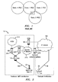
- Femto2 the femtocell denoted Femto2, Femto3 and Femto4 are neighbours of Femto 1.
- Femto4 and Femto3 both use the same primary scrambling code PSC1 whilst Femto1 uses a second primary scrambling code PSC2 and Femto2 uses a third primary scrambling code PSC3.
- Femto2 is so far away from Femto1 that Femto2 is not detected by sniffing by Femto1, however the user terminal detects Femto2 because Femto2 is much closer to the user terminal than to Femto 1.
- An example of the present invention is a method of obtaining at a first wireless telecommunications base station information about a neighbouring wireless telecommunications base station.
- the method comprises the following steps.
- the first base station receives a measurement report from a user terminal.
- the first base station determines from the measurement report that the user terminal has received a better signal from the neighbouring base station than from itself and instructs the user terminal to connect to the neighbouring base station.
- the first base station receives information of the neighbouring base station.
- the first base station stores the information of the neighbouring base station.
- the present invention also provides a first wireless telecommunications base station comprising apparatus for obtaining information of a neighbouring wireless telecommunications base station.
- the apparatus comprises: a measurement report receiver configured to receive a measurement report from a user terminal, and a processor configured to determine from the measurement report that the user terminal has received a better signal from the neighbouring base station than from the first base station and to instruct the user terminal to connect to the neighbouring base station.
- the processor is configured to receive information of the neighbouring base station.
- the apparatus also comprises a memory comprising a neighbour list configured to store, under the control of the processor, the information of the neighbouring base station.
- the present invention also provides a base station-controller gateway comprising: a detector to detect that there are connections to a user terminal both from a first base station and a neighbouring base station that is a neighbour to said first base station, a database configured to store information about the base stations, and a processor configured to look up information in the database so as to send information about the neighbouring base station to the first base station.
- relations to neighbouring femto base stations are readily determined. Hence the chance of dropping a call is reduced.
- neighbour information is obtained about neighbours that would not be disclosed by the known approach of sniffing.
- the first base station comprises a neighbour list and stores the information of the neighbouring base station in that neighbour list.
- the base stations are compliant with one or more of the 3GPP, UMTS, E-UMTS, and LTE standard.
- said information comprises a unique cell identifier, and preferably the cell identifier is a Cell ID.
- the base station-controller gateway is a femto-controlling gateway.
- the information identifies the neighbouring base station.
- the information comprises a unique cell identifier and may also comprise a primary scrambling code and a timing offset, in particular as applied to broadcast signals.
- a network 10 for wireless communications through which a user terminal 34 may roam, includes two types of base station, namely macrocell base stations and femtocell base stations (the latter being sometimes called "femtos").
- macrocell base stations are shown in Figures 2 and 3 for simplicity.
- Each macrocell base station has a radio coverage area 24 that is often referred to as a macrocell.
- the geographic extent of the macrocell 24 depends on the capabilities of the macrocell base station 22 and the surrounding geography.
- each femtocell base station 30 provides wireless communications within a corresponding femtocell 32.
- a femtocell is a radio coverage area.
- the radio coverage area of the femtocell 32 is much less than that of the macrocell 24.
- the femtocell 32 corresponds in size to a user's office or home.
- the network 10 is managed by a radio network controller, RNC, 170.
- the radio network controller, RNC, 170 controls the operation, for example by communicating with macrocell base stations 22 via a backhaul communications link 160.
- the radio network controller 170 maintains a neighbour list which includes information about the geographical relationship between cells supported by base stations.
- the radio network controller 170 maintains location information which provides information on the location of the user equipment within the wireless communications system 10.
- the radio network controller 170 is operable to route traffic via circuit-switched and packet-switched networks. For circuit-switched traffic, a mobile switching centre 250 is provided with which the radio network controller 170 may communicate.
- the mobile switching centre 250 communicates with a circuit-switched network such as a public switched telephone network (PSTN) 210.
- a circuit-switched network such as a public switched telephone network (PSTN) 210.
- PSTN public switched telephone network
- the network controller 170 communicates with service general packet radio service support nodes (SGSNs) 220 and a gateway general packet radio support node (GGSN) 180.
- the GGSN then communicates with a packet-switch core 190 such as, for example, the Internet.
- the MSC 250 , SGSN 220, GGSN 180 and operator IP network 215 constitute a so-called core network.
- the MSC 250, SGSN 220 and GGSN 180 are connected by an operator IP network 215 to a femtocell controller/gateway 230.
- the femtocell controller/gateway 230 is connected via the Internet 190 to the femtocell base stations 30. These connections to the femtocell controller/gateway 230 are broadband Internet Protocol connections ("backhaul”) connections.
- backhaul broadband Internet Protocol connections
- a mobile terminal 34 within the macrocell 24 it is possible for a mobile terminal 34 within the macrocell 24 to communicate with the macrocell base station 22 in known manner.
- the mobile terminal 34 enters into a femtocell 32 for which the mobile terminal is registered for communications within the femtocell base station 30, it is desirable to handover the connection with the mobile terminal from the macrocell to the femtocell.
- the user of mobile terminal 34 is a preferred user of the nearest 32' of the femtocells 32.
- the femtocell base stations 30 are connected via the broadband Internet Protocol connections ("backhaul") 36 to the core network (not shown in Figure 3 ) and hence the rest of the telecommunications "world” (not shown in Figure 3 ).
- the "backhaul" connections 36 allow communications between the femtocell base stations 30 through the core network (not shown).
- the macrocell base station is also connected to the core network (not shown in Figure 3 ).
- the femtocells 32 provide contiguous coverage, for example within an office building, and have six available primary scrambling codes.
- these six codes denoted PSC1,PSC2,.., PSC6 are distributed so as to avoid neighbouring cells having the same primary scrambling codes.
- a first femtocell 32a uses code PSC2, and has six neighbouring femtos, three of which are shown for simplicity in Figure 4 .
- one femtocell 32b uses a different code PSC3
- two femtocells 32c, 32d that also neighbour the first femtocell 32a use a further different code PSC1, being the same code as used by each other.
- each femtocell base station 30 includes a measurement report receiver 50, a connection releaser 52, and a memory 54 in which is stored a neighbour list 56, in other words a record of neighbouring femtocell base stations.
- the memory is under the control of a processor 51 that is connected to the measurement report receiver and the connection releaser 52
- a femtocell base station 30 is connected via its backhaul connection 36 to the femtocell controller/gateway 170.
- the femtocell controller/gateway 170 includes a detector 58, an interface 60, a gateway processor 62 and a database 64.
- the interface 60 is for connection to the femtocell base stations 30 via the backhaul connections 36.
- the detector is operative to detect that a connection to a user terminal exists both via a first femto (denoted Femto1 in Figure 5 ) and a second femto (denoted Femto2 in Figure 5 ).
- the database 64 keeps records of the Cell ID of neighbouring femtocells and additional information regarding those neighbours, namely PSC and Timing offset.
- the gateway processor 62 is operative to look up information in the database and attach information about Femto 2 (namely Cell ID, PSC and Timing Offset) to an Iu release command to be sent to Femto1. This is explained in more detail below.
- Femto 2 namely Cell ID, PSC and Timing Offset
- femto femtocell base station
- the first femto releases the connection with the user terminal so as to enable the user terminal to connect to the new femto.
- This new connection involves information about the new femto being passed to a femtocell controller/gateway from where information about that new femto is passed to the first femto which then updates its information about its neighbours.
- measurements of received signals by the user terminal provide the trigger for such a neighbour-relation learning operation as follows.
- the user terminal sends periodic measurement reports as to strength and quality of received signals that the user terminal detects.
- the user terminal is instead configured to send a measurement report when the signal received from a neighbour is detected as being sufficiently high.
- the first femto instructs the user terminal to release the connection, in other words to shift out of Cell_DCH state.
- Cell_DCH is a state in which there is a dedicated channel allocated between the user terminal and the femto.
- An example of such a call of acceptably low QoS is a packet-switched call that is inactive.
- Another example is a signalling bearer (channel) connection on which signalling has finished.
- the user terminal uses its cell selection/reselection mechanism in order to select for connection the femto that is indicated to the user terminal as providing the strongest/best quality signal to the user terminal. Connection to the new femto is then made, as part of which information about the new femto is passed to a femtocell controller/gateway. From the gateway, the information about the new femto is passed to the first femto which then updates its stored information about its neighbours.
- a measurement report is sent (step a) from the user terminal to the first Femto ("Femto 1").
- the measurement report is of a known type 1A or 1C as defined in Third Generation Partnership Project (3GPP) Technical Specification TS25.331.
- the measurement report indicates that a new femto ("Femto 2") is detected that provides a better quality connection than the current femto (“Femto 1").
- Femto 1 instructs (step b) the user terminal to release the connection.
- Femto 1 sends a Radio Resource Control (RRC) Connection Release command to the user terminal with a cause DSCR which triggers the user terminal to perform a Routing Area Update (RAU) procedure.
- RRC Radio Resource Control
- DSCR denotes cause Directed Signalling Connection Re-establishment (DSCR), and is defined in 3GPP technical specifications TS 25.331, TS 24.008, and TS 23. 060.
- This cause value is an instruction for the user terminal to transition into idle mode, select a new femto for connection to, and perform a routing area update (RAU) procedure so as to inform the SGSN of the new routing area for the user terminal.
- the user terminal replies (step c) with a RRC Connection Release Complete message.
- the user terminal then sends (step d) an RRC Connection request to the new Femto ("Femto2”) and the RRC connection is established (step e) between the user terminal and Femto2.
- the user terminal then performs (step f) a Routing Area Update (RAU) procedure via Femto 2 to the femtocell controller/gateway (denoted BSG, base station gateway, in Figure 6 ). From this RAU the femtocell controller gateway detects that the user terminal with resources established on Femto1 has now set up a connection on Femto2. As part of this procedure the Routing Area Update is forwarded by the femtocell controller/gateway to the core network (CN), specifically in this example, the SGSN.
- CN core network
- the core network detects the RAU and that resources associated with that user terminal are currently allocated on Femto1. Accordingly, the core network sends (step g) a resource release command, namely an Iu release command, to the femtocell controller/gateway (BSG).
- a resource release command namely an Iu release command
- the femtocell controller/gateway adds the Femto Identity (Cell ID), the primary scrambling code, and the timing information (all of Femto 2) to the Iu Release Command, and forwards (step h) this enhanced Iu Release Command to the first femto (Femto 1).
- the first femto (Femto 1) then checks (step i) that the primary scrambling code and timing offset information indicated via the enhanced Iu Release Command are consistent with the primary scrambling code and timing offset information determined from the measurement report provided by the user terminal, and assuming this consistency check is passed, adds (step j) the primary scrambling code, the Femto Identity (Cell ID), and timing information (all of Femto2) into its stored neighbour list.
- FIG. 7 Another example is shown in Figure 7 .
- the user terminal is sent into a connected mode state, namely Cell_FACH (Cell_Forward Access Channel) or Cell_PCH (Cell_Paging Channel) state, and cell reselection results in the new femto being selected.
- the new femto sends the RRC connection release command to release the user terminal's connection with the first femto (Femto 1).
- a measurement report is sent (step a') from the user terminal to the first Femto ("Femto 1").
- the measurement report is of a type 1A or 1C as defined in Third Generation Partnership Project (3GPP) Technical Specification TS25.331.
- the measurement report indicates that a new femto ("Femto 2") is detected that provides a better quality connection than the current femto (“Femto 1").
- the first femto instructs (step b') the user terminal to enter Cell_FACH or Cell_PCH state. Specifically, Femto 1 sends a Radio Resource Control (RRC) Radio Bearer Reconfiguration command to the user terminal.
- RRC Radio Resource Control
- the user terminal connects to Femto2 (step c') and sends a Cell Update message to Femto.
- the Cell Update message includes the user terminal's UTRAN radio network temporary identity (UE-U-RNTI) where UTRAN denotes UMTS terrestrial radio access network and UMTS denotes Universal Mobile Telecommunications System.
- UE-U-RNTI UTRAN radio network temporary identity
- Femto2 inspects the Cell Update message and detects that the UE-U-RNTI indicates a femto other than itself so sends (step d') an RRC Connection Release command to the user terminal.
- This command includes a cause DSCR which triggers the user terminal to perform a Routing Area Update (RAU) procedure.
- Cause DSCR denotes cause Directed Signalling Connection Re-establishment (DSCR), and is a message defined in 3GPP technical specifications TS 25.331, TS 24.008, and TS 23. 060.
- This cause value is a trigger for the user terminal to send an RRC Connection Request to Femto2 (in this example) and perform a routing area update (RAU) procedure so as to inform the SGSN of the new routing area for the user terminal.
- the user terminal sends (step e') an RRC Connection request to the new Femto ("Femto2") and the RRC connection is established (step f) between the user terminal and Femto2.
- the user terminal then performs (step g') a Routing Area Update (RAU) procedure via Femto 2 to the femtocell controller/gateway (denoted BSG, base station gateway, in Figure 7 ).
- RAU Routing Area Update
- the Routing Area update is forwarded (step h') by the femtocell controller/gateway to the core network (CN), specifically the SGSN.
- CN core network
- the core network detects the RAU and that resources associated with that user terminal are currently allocated to Femto1. Accordingly, the core network sends (step i') a resource release command, namely an Iu release command, to the femtocell controller/gateway (BSG).
- a resource release command namely an Iu release command
- the femtocell controller/gateway adds the Femto Identity (Cell ID), the primary scrambling code and timing information (all of Femto 2) to the Iu Release Command, and forwards (step j') this enhanced Iu Release Command to the first femto (Femto 1).
- the first femto (Femto 1) then checks (step k') that the primary scrambling code and timing offset information indicated via the enhanced Iu Release Command are consistent with the primary scrambling code and timing offset information determined from the measurement report provided by the user terminal, and assuming this consistency check is passed, adds (step 1') the primary scrambling code, the Femto Identity (Cell ID), and timing information (all of Femto2) into its stored neighbour list.
- the RAU procedure causes the femtocell controller/gateway to be notified of the user terminal becoming connected to the new femto whilst there is still an existing connection with another ("old") femto.
- the gateway releases the resources related to the user terminal in the old femto and as part of this provides the old femto with information about the new femto that the user terminal has connected to.
- the information of the new femto includes or consists of its Cell ID.
- the PSC and the Timing information are used to confirm the identity of the new femto. (In some other embodiments, these PSC and/or timing checks are not undertaken). Specifically in the Figure 6 and Figure 7 embodiments, a check is made whether the PSC in the initial measurement report matches the femto PSC provided from the femtocell controller/ gateway. Furthermore, a check is made whether the timing indicated in the initial measurement report is consistent with the timing information provided by the femtocell controller/gateway. The timing information is the synchronisation timing, in other words the timing offset of the 'new' femto. If yes, namely the PSC and timing information is consistent, the new femto is included in the neighbour list of the original femto. If no, the data is discarded.
- the first ('old') femto acts to correlate the PSC information in the Iu release command with the PSC information in the user terminal measurement report.
- the first femto also correlates the timing offset information in the Iu release command with the information of timing in the user terminal measurement report and the time required for the Iu Release command to be transmitted.
- the old femto maintains call connections for longer than otherwise before releasing them, in order to allow ample time for this learning about network topology (In some other embodiments, the old femto does not maintain call connections for longer).
- the old femto does not maintain call connections for longer.
- few new neighbour relationships are discovered, in other words each femto has a fairly up to date neighbour list.
- the learning phase is then terminated, and instead upon a better quality femto being detected that is in the neighbour list, simple handover as known to someone skilled in the art is undertaken.
- a femto may decide a further such learning phase is required based upon a criterion or combination of criteria such as the percentage of failed handovers exceeding a certain limit, receiving measurement reports from user terminals that refer to a PSC that is not currently listed in the neighbour list, or receiving measurement reports from user terminals indicating timing information that does not match the timing of currently known neighbours.
- the neighbouring femtocell base station rather than the femtocell controller/gateway providing information of the neighbouring femtocell base station, the neighbouring femtocell base station itself provides information of itself to the first femtocell base station via the DSL backhaul.
- the first femtocell base station having just released the connection to the user terminal, identifies that that neighbouring base station is "newly known" to the first femtocell base station and so records the information of that neighbouring femtocell base station.
- the first femtocell base station receives the measurement report "trigger" to transfer the connection, but before releasing the user terminal informs the other femtocell base stations via the DSL backhaul of the user terminal being released.
- the neighbouring femtocell base station Upon the user terminal connecting to the neighbouring femtocell base station, the neighbouring femtocell base station knows of the transfer from the first femotcell base station and so informs the first femtocell base station about itself.
- program storage devices e.g., digital data storage media, which are machine or computer readable and encode machine-executable or computer-executable programs of instructions, wherein said instructions perform some or all of the steps of said above-described methods.
- the program storage devices may be, e.g., digital memories, magnetic storage media such as a magnetic disks and magnetic tapes, hard drives, or optically readable digital data storage media.
- Some embodiments involve computers programmed to perform said steps of the above-described methods.
Abstract
Description
- The present invention relates to telecommunications, in particular to wireless telecommunications.
- Wireless telecommunications systems are well-known. Many such systems are cellular in that radio coverage is provided by a bundle of radio coverage areas known as cells. A base station that provides radio coverage is located in each cell. Traditional base stations provide coverage in relatively large geographic areas and the corresponding cells are often referred to as macrocells.
- It is possible to establish smaller sized cells within a macrocell. Cells that are smaller than macrocells are sometimes referred to as microcells, picocells, or femtocells, but we use the term femtocells generically for cells that are smaller than macrocells. One way to establish a femtocell is to provide a femtocell base station that operates within a relatively limited range within the coverage area of a macrocell. One example of use of a femtocell base station is to provide wireless communication coverage within a building.
- The femtocell base station is of a relatively low transmit power and hence each femtocell is of a small coverage area compared to a macrocell.
- Femtocell base stations are intended primarily for users belonging to a particular home or office. Femtocell base stations may be private access or public access. In femtocell base stations that are private access, access is restricted only to registered users, for example family members or particular groups of employees. In femtocell base stations that are public access, other users may also use the femtocell base station, subject to certain restrictions to protect the Quality of Service received by registered users.
- One known type of Femtocell base station uses a broadband Internet Protocol connection as "backhaul", namely for connecting to the core network. One type of broadband Internet Protocol connection is a Digital Subscriber Line (DSL). The DSL connects a DSL transmitter-receiver ("transceiver") of the femtocell base station to the core network. The DSL allows voice calls and other services provided via the femtocell base station to be supported. The femtocell base station also includes a radio frequency (RF) transceiver connected to an antenna for radio communications.
- Femtocell base stations are sometimes referred to as femtos.
- One problem of femtocell base stations, particularly those involving code division multiple access, such as those in accordance with current Third Generation Partnership Project (3GPP) Universal Mobile Telecommunications System (UMTS) standards, is that there are few primary scrambling codes (PSCs) available. Primary scrambling codes are broadcast by base stations over the radio interface and are used to distinguish between neighbouring base stations. Typically, there are between six and sixteen PSCs that are available to the femtocells. The PSC to be used by each femtocell base station is normally selected by an automatic configuration process based on measurements made by that femtocell base station. For example, a femto detects from received signals which PSCs are in use around that femto, and selects a PSC that the femto has not detected as being in use, else selects the PSC of the weakest signal received. In consequence, typically each of the available primary scrambling codes is used by multiple femtos, in other words much primary scrambling code "re-use".
- As is known, user terminals in a cell make measurements as to signals received from other nearby base stations and report these measurements to the base station of that cell. This is so as to determine whether it is appropriate to handover the call connection with the user terminal from that cell to another cell from which a stronger or better quality signal is received.
- With this level of PSC reuse, there is a strong chance that user terminals served by a femto will detect signals from multiple different cells having the same primary scrambling code. There is no unique cell identifier, often denoted Cell ID, reported in the user terminal's measurement report according to current 3GPP standards. Accordingly, there is ambiguity or uncertainty as to which of the neighbouring femtos using that PSC provides the best signal to the user terminal and so should be the handover target.
- A known approach is to seek to handover to all of the femtocells that are identified as using the primary scrambling code of the best received signal. This is inefficient because only one of the handover attempts is permitted to succeed. Network resources are wasted that are used in the handover attempts to the other femtocells than the one that is successful.
- To determine which of the neighbouring femtos using that PSC provides the best signal to the user terminal and so should be the handover target, a known approach is for the femtocell base station to cease to transmit and instead receive at the frequency that user terminals receive at, in order to detect neighbouring femtos. This is known as sniffing. This works in detecting neighbouring femtos that are strongly transmitting, but may not detect every femto that the user terminal would detect as a handover candidate.
- An example of the prior art approach involving sniffing is shown in
Figure 1 . - As shown in
Figure 1 , the femtocell denoted Femto2, Femto3 and Femto4 are neighbours ofFemto 1. Femto4 and Femto3 both use the same primary scrambling code PSC1 whilst Femto1 uses a second primary scrambling code PSC2 and Femto2 uses a third primary scrambling code PSC3. In this example, Femto2 is so far away from Femto1 that Femto2 is not detected by sniffing by Femto1, however the user terminal detects Femto2 because Femto2 is much closer to the user terminal than toFemto 1. - The reader is referred to the appended independent claims. Some preferred features are laid out in the dependent claims.
- An example of the present invention is a method of obtaining at a first wireless telecommunications base station information about a neighbouring wireless telecommunications base station. The method comprises the following steps. The first base station receives a measurement report from a user terminal. The first base station determines from the measurement report that the user terminal has received a better signal from the neighbouring base station than from itself and instructs the user terminal to connect to the neighbouring base station. The first base station receives information of the neighbouring base station. The first base station stores the information of the neighbouring base station.
- The present invention also provides a first wireless telecommunications base station comprising apparatus for obtaining information of a neighbouring wireless telecommunications base station. The apparatus comprises: a measurement report receiver configured to receive a measurement report from a user terminal, and a processor configured to determine from the measurement report that the user terminal has received a better signal from the neighbouring base station than from the first base station and to instruct the user terminal to connect to the neighbouring base station. The processor is configured to receive information of the neighbouring base station. The apparatus also comprises a memory comprising a neighbour list configured to store, under the control of the processor, the information of the neighbouring base station.
- The present invention also provides a base station-controller gateway comprising: a detector to detect that there are connections to a user terminal both from a first base station and a neighbouring base station that is a neighbour to said first base station, a database configured to store information about the base stations, and a processor configured to look up information in the database so as to send information about the neighbouring base station to the first base station.
- In some preferred embodiments, in this way relations to neighbouring femto base stations are readily determined. Hence the chance of dropping a call is reduced.
- In some embodiments, neighbour information is obtained about neighbours that would not be disclosed by the known approach of sniffing.
- Furthermore, preferably the first base station comprises a neighbour list and stores the information of the neighbouring base station in that neighbour list.
- Furthermore, preferably the base stations are compliant with one or more of the 3GPP, UMTS, E-UMTS, and LTE standard.
- Still furthermore, preferably said information comprises a unique cell identifier, and preferably the cell identifier is a Cell ID.
- Preferably the base station-controller gateway is a femto-controlling gateway.
- Preferably the information identifies the neighbouring base station. Preferably, the information comprises a unique cell identifier and may also comprise a primary scrambling code and a timing offset, in particular as applied to broadcast signals.
- Embodiments of the present invention will now be described by way of example and with reference to the drawings, in which:
-
Figure 1 is a diagram illustrating a known approach to identifying handover candidates for a user terminal (PRIOR ART), -
Figure 2 is a diagram illustrating a wireless communications network according to an embodiment of the present invention, and -
Figure 3 is a diagram illustrating an example femtocell base station deployment within one macrocell in the network shown inFigure 2 , -
Figure 4 is a diagram illustrating allocation of primary scrambling codes to femtocells within the network shown inFigure 2 , -
Figure 5 is a diagram illustrating in more detail the femtocell controller/gateway and two of the femtocell base stations, in the network shown inFigure 2 . -
Figure 6 is a message sequence diagram illustrating an example of identifying neighbour femtocell base stations in the network shown inFigure 2 , and -
Figure 7 is a message sequence diagram illustrating a second example of identifying neighbour femtocell base stations in the network shown inFigure 2 . - We now describe a network including femtocell base stations then look in greater detail at a femtocell base station and the relevant operation of the femtocell base station.
- As shown in
Figures 2 and3 , anetwork 10 for wireless communications, through which auser terminal 34 may roam, includes two types of base station, namely macrocell base stations and femtocell base stations (the latter being sometimes called "femtos"). Onemacrocell base station 22 is shown inFigures 2 and3 for simplicity. Each macrocell base station has aradio coverage area 24 that is often referred to as a macrocell. The geographic extent of themacrocell 24 depends on the capabilities of themacrocell base station 22 and the surrounding geography. - Within the
macrocell 24, eachfemtocell base station 30 provides wireless communications within a correspondingfemtocell 32. A femtocell is a radio coverage area. The radio coverage area of thefemtocell 32 is much less than that of themacrocell 24. For example, thefemtocell 32 corresponds in size to a user's office or home. - As shown in
Figure 2 , thenetwork 10 is managed by a radio network controller, RNC, 170. The radio network controller, RNC, 170 controls the operation, for example by communicating withmacrocell base stations 22 via a backhaul communications link 160. Theradio network controller 170 maintains a neighbour list which includes information about the geographical relationship between cells supported by base stations. In addition, theradio network controller 170 maintains location information which provides information on the location of the user equipment within thewireless communications system 10. Theradio network controller 170 is operable to route traffic via circuit-switched and packet-switched networks. For circuit-switched traffic, amobile switching centre 250 is provided with which theradio network controller 170 may communicate. Themobile switching centre 250 communicates with a circuit-switched network such as a public switched telephone network (PSTN) 210. For packet-switched traffic, thenetwork controller 170 communicates with service general packet radio service support nodes (SGSNs) 220 and a gateway general packet radio support node (GGSN) 180. The GGSN then communicates with a packet-switch core 190 such as, for example, the Internet. - The
MSC 250 ,SGSN 220,GGSN 180 andoperator IP network 215 constitute a so-called core network. TheMSC 250,SGSN 220 andGGSN 180 are connected by anoperator IP network 215 to a femtocell controller/gateway 230. - The femtocell controller/
gateway 230 is connected via theInternet 190 to thefemtocell base stations 30. These connections to the femtocell controller/gateway 230 are broadband Internet Protocol connections ("backhaul") connections. - In
Figure 3 , threefemtocell base stations 30 andcorresponding femtocells 32 are shown for simplicity. - It is possible for a
mobile terminal 34 within themacrocell 24 to communicate with themacrocell base station 22 in known manner. When themobile terminal 34 enters into afemtocell 32 for which the mobile terminal is registered for communications within thefemtocell base station 30, it is desirable to handover the connection with the mobile terminal from the macrocell to the femtocell. In the example shown inFigure 3 , the user ofmobile terminal 34 is a preferred user of the nearest 32' of thefemtocells 32. - As shown in
Figure 3 , thefemtocell base stations 30 are connected via the broadband Internet Protocol connections ("backhaul") 36 to the core network (not shown inFigure 3 ) and hence the rest of the telecommunications "world" (not shown inFigure 3 ). The "backhaul"connections 36 allow communications between thefemtocell base stations 30 through the core network (not shown). The macrocell base station is also connected to the core network (not shown inFigure 3 ). - As shown in
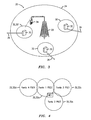
Figure 4 , thefemtocells 32 provide contiguous coverage, for example within an office building, and have six available primary scrambling codes. In this example, these six codes, denoted PSC1,PSC2,.., PSC6 are distributed so as to avoid neighbouring cells having the same primary scrambling codes. Specifically, a first femtocell 32a uses code PSC2, and has six neighbouring femtos, three of which are shown for simplicity inFigure 4 . Of these neighbouring femtos, one femtocell 32b uses a different code PSC3, and two femtocells 32c, 32d that also neighbour the first femtocell 32a use a further different code PSC1, being the same code as used by each other. - As shown in
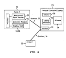
Figure 5 , eachfemtocell base station 30 includes ameasurement report receiver 50, aconnection releaser 52, and a memory 54 in which is stored a neighbour list 56, in other words a record of neighbouring femtocell base stations. The memory is under the control of a processor 51 that is connected to the measurement report receiver and theconnection releaser 52 - As also shown in
Figure 5 , afemtocell base station 30 is connected via itsbackhaul connection 36 to the femtocell controller/gateway 170. - The femtocell controller/
gateway 170 includes adetector 58, aninterface 60, agateway processor 62 and adatabase 64. Theinterface 60 is for connection to thefemtocell base stations 30 via thebackhaul connections 36. The detector is operative to detect that a connection to a user terminal exists both via a first femto (denoted Femto1 inFigure 5 ) and a second femto (denoted Femto2 inFigure 5 ). - The
database 64 keeps records of the Cell ID of neighbouring femtocells and additional information regarding those neighbours, namely PSC and Timing offset. - The
gateway processor 62 is operative to look up information in the database and attach information about Femto 2 (namely Cell ID, PSC and Timing Offset) to an Iu release command to be sent to Femto1. This is explained in more detail below. - In the situation that a first ("old") femtocell base station ("femto") is connected to a user terminal that detects a new neighbour femto with sufficient quality, the first femto releases the connection with the user terminal so as to enable the user terminal to connect to the new femto. This new connection involves information about the new femto being passed to a femtocell controller/gateway from where information about that new femto is passed to the first femto which then updates its information about its neighbours.
- More specifically, measurements of received signals by the user terminal provide the trigger for such a neighbour-relation learning operation as follows.
- The user terminal sends periodic measurement reports as to strength and quality of received signals that the user terminal detects. In an alternative embodiment, the user terminal is instead configured to send a measurement report when the signal received from a neighbour is detected as being sufficiently high.
- In the situation that the user terminal both detects that signals from the new femto are of much stronger strength and (/or) quality than the first femto, and the call is of a type given an acceptably low Quality of Service (QoS) such that the user terminal can be released from Cell_DCH state, then the first femto instructs the user terminal to release the connection, in other words to shift out of Cell_DCH state. Cell_DCH is a state in which there is a dedicated channel allocated between the user terminal and the femto. An example of such a call of acceptably low QoS is a packet-switched call that is inactive. Another example is a signalling bearer (channel) connection on which signalling has finished.
- The user terminal then uses its cell selection/reselection mechanism in order to select for connection the femto that is indicated to the user terminal as providing the strongest/best quality signal to the user terminal. Connection to the new femto is then made, as part of which information about the new femto is passed to a femtocell controller/gateway. From the gateway, the information about the new femto is passed to the first femto which then updates its stored information about its neighbours.
- This approach will be described in further detail by way of two examples.
- As shown in
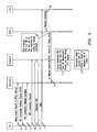
Figure 6 , a measurement report is sent (step a) from the user terminal to the first Femto ("Femto 1"). The measurement report is of a knowntype 1A or 1C as defined in Third Generation Partnership Project (3GPP) Technical Specification TS25.331. The measurement report indicates that a new femto ("Femto 2") is detected that provides a better quality connection than the current femto ("Femto 1"). - After checking and being satisfied that the call is of an acceptably low Quality of Service (QoS) type that the connection with the user terminal can be released, the first femto ("
Femto 1") instructs (step b) the user terminal to release the connection. Specifically,Femto 1 sends a Radio Resource Control (RRC) Connection Release command to the user terminal with a cause DSCR which triggers the user terminal to perform a Routing Area Update (RAU) procedure. Cause DSCR denotes cause Directed Signalling Connection Re-establishment (DSCR), and is defined in 3GPP technical specifications TS 25.331, TS 24.008, and TS 23. 060. This cause value is an instruction for the user terminal to transition into idle mode, select a new femto for connection to, and perform a routing area update (RAU) procedure so as to inform the SGSN of the new routing area for the user terminal. - The user terminal replies (step c) with a RRC Connection Release Complete message.
- The user terminal then sends (step d) an RRC Connection request to the new Femto ("Femto2") and the RRC connection is established (step e) between the user terminal and Femto2. The user terminal then performs (step f) a Routing Area Update (RAU) procedure via
Femto 2 to the femtocell controller/gateway (denoted BSG, base station gateway, inFigure 6 ). From this RAU the femtocell controller gateway detects that the user terminal with resources established on Femto1 has now set up a connection on Femto2. As part of this procedure the Routing Area Update is forwarded by the femtocell controller/gateway to the core network (CN), specifically in this example, the SGSN. - The core network detects the RAU and that resources associated with that user terminal are currently allocated on Femto1. Accordingly, the core network sends (step g) a resource release command, namely an Iu release command, to the femtocell controller/gateway (BSG).
- The femtocell controller/gateway (BSG) adds the Femto Identity (Cell ID), the primary scrambling code, and the timing information (all of Femto 2) to the Iu Release Command, and forwards (step h) this enhanced Iu Release Command to the first femto (Femto 1).
- The first femto (Femto 1) then checks (step i) that the primary scrambling code and timing offset information indicated via the enhanced Iu Release Command are consistent with the primary scrambling code and timing offset information determined from the measurement report provided by the user terminal, and assuming this consistency check is passed, adds (step j) the primary scrambling code, the Femto Identity (Cell ID), and timing information (all of Femto2) into its stored neighbour list.
- Another example is shown in
Figure 7 . In this example the user terminal is sent into a connected mode state, namely Cell_FACH (Cell_Forward Access Channel) or Cell_PCH (Cell_Paging Channel) state, and cell reselection results in the new femto being selected. The new femto sends the RRC connection release command to release the user terminal's connection with the first femto (Femto 1). - As shown in
Figure 7 , a measurement report is sent (step a') from the user terminal to the first Femto ("Femto 1"). The measurement report is of atype 1A or 1C as defined in Third Generation Partnership Project (3GPP) Technical Specification TS25.331. The measurement report indicates that a new femto ("Femto 2") is detected that provides a better quality connection than the current femto ("Femto 1"). - After checking and being satisfied that the call is of an acceptably low Quality of Service (QoS) type that the connection with the user terminal can be released, the first femto ("
Femto 1") instructs (step b') the user terminal to enter Cell_FACH or Cell_PCH state. Specifically,Femto 1 sends a Radio Resource Control (RRC) Radio Bearer Reconfiguration command to the user terminal. - The user terminal connects to Femto2 (step c') and sends a Cell Update message to Femto. The Cell Update message includes the user terminal's UTRAN radio network temporary identity (UE-U-RNTI) where UTRAN denotes UMTS terrestrial radio access network and UMTS denotes Universal Mobile Telecommunications System.
- Femto2 inspects the Cell Update message and detects that the UE-U-RNTI indicates a femto other than itself so sends (step d') an RRC Connection Release command to the user terminal. This command includes a cause DSCR which triggers the user terminal to perform a Routing Area Update (RAU) procedure. Cause DSCR denotes cause Directed Signalling Connection Re-establishment (DSCR), and is a message defined in 3GPP technical specifications TS 25.331, TS 24.008, and TS 23. 060. This cause value is a trigger for the user terminal to send an RRC Connection Request to Femto2 (in this example) and perform a routing area update (RAU) procedure so as to inform the SGSN of the new routing area for the user terminal.
- Accordingly, the user terminal sends (step e') an RRC Connection request to the new Femto ("Femto2") and the RRC connection is established (step f) between the user terminal and Femto2. The user terminal then performs (step g') a Routing Area Update (RAU) procedure via
Femto 2 to the femtocell controller/gateway (denoted BSG, base station gateway, inFigure 7 ). As part of this procedure the Routing Area update is forwarded (step h') by the femtocell controller/gateway to the core network (CN), specifically the SGSN. - The core network detects the RAU and that resources associated with that user terminal are currently allocated to Femto1. Accordingly, the core network sends (step i') a resource release command, namely an Iu release command, to the femtocell controller/gateway (BSG).
- The femtocell controller/gateway (BSG) adds the Femto Identity (Cell ID), the primary scrambling code and timing information (all of Femto 2) to the Iu Release Command, and forwards (step j') this enhanced Iu Release Command to the first femto (Femto 1).
- The first femto (Femto 1) then checks (step k') that the primary scrambling code and timing offset information indicated via the enhanced Iu Release Command are consistent with the primary scrambling code and timing offset information determined from the measurement report provided by the user terminal, and assuming this consistency check is passed, adds (step 1') the primary scrambling code, the Femto Identity (Cell ID), and timing information (all of Femto2) into its stored neighbour list.
- It will be noted that in both the examples shown in
Figures 6 and7 , the RAU procedure causes the femtocell controller/gateway to be notified of the user terminal becoming connected to the new femto whilst there is still an existing connection with another ("old") femto. The gateway releases the resources related to the user terminal in the old femto and as part of this provides the old femto with information about the new femto that the user terminal has connected to. - The information of the new femto includes or consists of its Cell ID. In some embodiments, such as described with reference to
Figures 6 and7 above, the PSC and the Timing information are used to confirm the identity of the new femto. (In some other embodiments, these PSC and/or timing checks are not undertaken). Specifically in theFigure 6 andFigure 7 embodiments, a check is made whether the PSC in the initial measurement report matches the femto PSC provided from the femtocell controller/ gateway. Furthermore, a check is made whether the timing indicated in the initial measurement report is consistent with the timing information provided by the femtocell controller/gateway. The timing information is the synchronisation timing, in other words the timing offset of the 'new' femto. If yes, namely the PSC and timing information is consistent, the new femto is included in the neighbour list of the original femto. If no, the data is discarded. - In other words, the first ('old') femto acts to correlate the PSC information in the Iu release command with the PSC information in the user terminal measurement report. The first femto also correlates the timing offset information in the Iu release command with the information of timing in the user terminal measurement report and the time required for the Iu Release command to be transmitted. By way of these two correlations, a determination is made whether the information of the 'new' femto as a neighbour appears valid and if so it is recorded in the 'old' femto's neighbour list.
- During this learning phase, the old femto maintains call connections for longer than otherwise before releasing them, in order to allow ample time for this learning about network topology (In some other embodiments, the old femto does not maintain call connections for longer). After some time, few new neighbour relationships are discovered, in other words each femto has a fairly up to date neighbour list. The learning phase is then terminated, and instead upon a better quality femto being detected that is in the neighbour list, simple handover as known to someone skilled in the art is undertaken.
- In due course, a femto may decide a further such learning phase is required based upon a criterion or combination of criteria such as the percentage of failed handovers exceeding a certain limit, receiving measurement reports from user terminals that refer to a PSC that is not currently listed in the neighbour list, or receiving measurement reports from user terminals indicating timing information that does not match the timing of currently known neighbours.
- In some otherwise similar embodiments, rather than the femtocell controller/gateway providing information of the neighbouring femtocell base station, the neighbouring femtocell base station itself provides information of itself to the first femtocell base station via the DSL backhaul. In a first example, the neighbour base station that the connection is transferred to sends the information about itself via the backhaul to other femtocell base stations that it is aware of. The first femtocell base station, having just released the connection to the user terminal, identifies that that neighbouring base station is "newly known" to the first femtocell base station and so records the information of that neighbouring femtocell base station.
- In a second example, the first femtocell base station receives the measurement report "trigger" to transfer the connection, but before releasing the user terminal informs the other femtocell base stations via the DSL backhaul of the user terminal being released. Upon the user terminal connecting to the neighbouring femtocell base station, the neighbouring femtocell base station knows of the transfer from the first femotcell base station and so informs the first femtocell base station about itself.
- The present invention may be embodied in other specific forms without departing from its essential characteristics. The described embodiments are to be considered in all respects only as illustrative and not restrictive. The scope of the invention is, therefore, indicated by the appended claims rather than by the foregoing description. All changes that come within the meaning and range of equivalency of the claims are to be embraced within their scope.
- A person skilled in the art would readily recognize that steps of various above-described methods can be performed by programmed computers. Some embodiments relate to program storage devices, e.g., digital data storage media, which are machine or computer readable and encode machine-executable or computer-executable programs of instructions, wherein said instructions perform some or all of the steps of said above-described methods. The program storage devices may be, e.g., digital memories, magnetic storage media such as a magnetic disks and magnetic tapes, hard drives, or optically readable digital data storage media. Some embodiments involve computers programmed to perform said steps of the above-described methods.
Claims (15)
- A method of obtaining at a first wireless telecommunications base station information of a neighbouring wireless telecommunications base station, the method comprising:the first base station receiving a measurement report from a user terminalthe first base station determining from the measurement report that the user terminal has received a better signal from the neighbouring base station than from the first base station and instructing the user terminal to connect to the neighbouring base station,the first base station receiving information of the neighbouring base station,the first base station storing the information of the neighbouring base station.
- A method according to claim 1, in which the first base station receives the information of the neighbouring base station from a base station-controlling gateway.
- A method according to claim 1, in which the first base station receives the information of the neighbouring base station from the neighbouring base station.
- A method according to claim 3, in which the first base station notifies the base station-controlling gateway of information of the neighbouring base station and identity of the user terminal.
- A method according to any preceding claim, further comprising:the neighbouring base station connecting to the user terminal,the first base station releasing its connection to the user terminal upon receiving a release command comprising said information of the neighbouring base station.
- A method according to any preceding claim, in which the better signal received by the user terminal is of at least one of a higher received signal strength or better quality than the signal received by the user terminal from the first base station.
- A method according to any preceding claim, in which the base stations are femtocell base stations.
- A method according to any preceding claim, in which said information comprises a unique cell identifier.
- A method according to claim 8, in which said information also comprises a primary scrambling code, and in which the first base station compares the primary scrambling code from the base station-controlling gateway to that indicated in the measurement report from the user terminal, and the first base station stores the information of the neighbouring base station dependent upon the primary scrambling code comparison indicating a match.
- A method according to claim 8 or claim 9, in which said information also comprises timing offset of the base station clock, and in which the first base station compares the timing offset of the neighbouring base station indicated by the base station-controlling gateway to that indicated in the measurement report from the user terminal, and the first base station stores the information of the neighbouring base station dependent upon the timing offset comparison indicating a match.
- A method according to any preceding claim in which the first base station enters a learning phase during which the connection to the first base station is maintained long enough for the connection to the neighbouring base station to become established and the base station-controlling gateway to send said information of the neighbouring base station to the first base station.
- A first wireless telecommunications base station comprising apparatus for obtaining information of a neighbouring wireless telecommunications base station, the apparatus comprising:a measurement report receiver configured to receive a measurement report from a user terminal,a processor configured to determine from the measurement report that the user terminal has received a better signal from the neighbouring base station than from the first base station and configured to instruct the user terminal to connect to the neighbouring base station,the processor being configured to receive information of the neighbouring base station, anda memory comprising a neighbour list configured to store, under the control of the processor, the information of the neighbouring base station.
- A base station-controller gateway comprising a detector to detect that there are connections to a user terminal both from a first base station and a neighbouring base station that is a neighbour to said first base station,
a database configured to store information about the base stations,
a processor configured to look up information in the database so as to send information about the neighbouring base station to the first base station. - A base station-controller gateway according to claim 13 in which the information is sent in a connection release command to the first base station.
- A base station-controller gateway according to claim 13 or claim 14 in which the information comprises one or more of a unique cell identifier, a primary scrambling code and a timing offset.
Priority Applications (1)
| Application Number | Priority Date | Filing Date | Title |
|---|---|---|---|
| EP09290336.8A EP2249603B1 (en) | 2009-05-07 | 2009-05-07 | Obtaining information of a neighbouring base station |
Applications Claiming Priority (1)
| Application Number | Priority Date | Filing Date | Title |
|---|---|---|---|
| EP09290336.8A EP2249603B1 (en) | 2009-05-07 | 2009-05-07 | Obtaining information of a neighbouring base station |
Publications (2)
| Publication Number | Publication Date |
|---|---|
| EP2249603A1 true EP2249603A1 (en) | 2010-11-10 |
| EP2249603B1 EP2249603B1 (en) | 2013-07-10 |
Family
ID=41119915
Family Applications (1)
| Application Number | Title | Priority Date | Filing Date |
|---|---|---|---|
| EP09290336.8A Not-in-force EP2249603B1 (en) | 2009-05-07 | 2009-05-07 | Obtaining information of a neighbouring base station |
Country Status (1)
| Country | Link |
|---|---|
| EP (1) | EP2249603B1 (en) |
Cited By (4)
| Publication number | Priority date | Publication date | Assignee | Title |
|---|---|---|---|---|
| EP2521110A1 (en) * | 2011-05-06 | 2012-11-07 | Alcatel Lucent | A small cell base station, a method of controlling movement of a machine-type-communication (MTC) unit, and a braking system for a vehicle |
| WO2014071392A1 (en) * | 2012-11-05 | 2014-05-08 | Qualcomm Incorporated | Psc transmission with time offset for unique small cell identification |
| EP2763460A4 (en) * | 2011-09-27 | 2015-10-28 | Nec Corp | Gateway, control device, and communication control method therefor |
| DE102012100519B4 (en) * | 2011-01-24 | 2017-03-16 | Infineon Technologies Ag | Detection and elimination of performance degradation caused by adjacent identical scrambling codes |
Citations (5)
| Publication number | Priority date | Publication date | Assignee | Title |
|---|---|---|---|---|
| EP1432262A1 (en) | 2002-12-20 | 2004-06-23 | Matsushita Electric Industrial Co., Ltd. | Protocol context preservation in mobile communication systems |
| US20050272426A1 (en) * | 2002-12-13 | 2005-12-08 | Da Tang Mobile Communications Equipment Co., Ltd. | Handover method in mobile communication system |
| US20070010252A1 (en) * | 2005-07-07 | 2007-01-11 | Kumar Balachandran | Method and base station controller for handover of simultaneous voice and data sessions |
| WO2007110659A1 (en) * | 2006-03-27 | 2007-10-04 | Nokia Siemens Networks Gmbh & Co. Kg | Indication of content of a message element |
| EP2037696A1 (en) * | 2006-07-05 | 2009-03-18 | Huawei Technologies Co., Ltd. | Cell handover method and apparatus |
-
2009
- 2009-05-07 EP EP09290336.8A patent/EP2249603B1/en not_active Not-in-force
Patent Citations (5)
| Publication number | Priority date | Publication date | Assignee | Title |
|---|---|---|---|---|
| US20050272426A1 (en) * | 2002-12-13 | 2005-12-08 | Da Tang Mobile Communications Equipment Co., Ltd. | Handover method in mobile communication system |
| EP1432262A1 (en) | 2002-12-20 | 2004-06-23 | Matsushita Electric Industrial Co., Ltd. | Protocol context preservation in mobile communication systems |
| US20070010252A1 (en) * | 2005-07-07 | 2007-01-11 | Kumar Balachandran | Method and base station controller for handover of simultaneous voice and data sessions |
| WO2007110659A1 (en) * | 2006-03-27 | 2007-10-04 | Nokia Siemens Networks Gmbh & Co. Kg | Indication of content of a message element |
| EP2037696A1 (en) * | 2006-07-05 | 2009-03-18 | Huawei Technologies Co., Ltd. | Cell handover method and apparatus |
Cited By (6)
| Publication number | Priority date | Publication date | Assignee | Title |
|---|---|---|---|---|
| DE102012100519B4 (en) * | 2011-01-24 | 2017-03-16 | Infineon Technologies Ag | Detection and elimination of performance degradation caused by adjacent identical scrambling codes |
| EP2521110A1 (en) * | 2011-05-06 | 2012-11-07 | Alcatel Lucent | A small cell base station, a method of controlling movement of a machine-type-communication (MTC) unit, and a braking system for a vehicle |
| EP2763460A4 (en) * | 2011-09-27 | 2015-10-28 | Nec Corp | Gateway, control device, and communication control method therefor |
| US9578662B2 (en) | 2011-09-27 | 2017-02-21 | Nec Corporation | Gateway and control device, and communication controlling methods for the same |
| WO2014071392A1 (en) * | 2012-11-05 | 2014-05-08 | Qualcomm Incorporated | Psc transmission with time offset for unique small cell identification |
| US9198092B2 (en) | 2012-11-05 | 2015-11-24 | Qualcomm Incorporated | PSC transmission with time offset for unique small cell identification |
Also Published As
| Publication number | Publication date |
|---|---|
| EP2249603B1 (en) | 2013-07-10 |
Similar Documents
| Publication | Publication Date | Title |
|---|---|---|
| KR101194436B1 (en) | Source initiated communication handover | |
| KR101376250B1 (en) | Method and apparatus of resolving pci confusion for providing inbound mobility to closed subscriber group | |
| US20100093358A1 (en) | Wireless communication system and handover method therein | |
| US8868077B2 (en) | Method and apparatus for topology management for handovers in heterogeneous networks | |
| WO2009056028A1 (en) | Methods, devices, and systems of providing measurement information and detecting coverage problem | |
| EP2320699A1 (en) | A Femtocell base station, and a method of triggering transfer of a radio connection with a user terminal from a macrocell base station to a femtocell base station | |
| KR101551517B1 (en) | Method for re-establishing rrc connection and mobile telecommunication system for the same | |
| KR20110019715A (en) | Method for transmitting and receiving information of relation between home base stations | |
| US20120258718A1 (en) | Femtocell Base Station | |
| US9220040B2 (en) | Femto-gateway, a cellular telecommunications network, and a method of identifying a handover target femtocell base station | |
| EP2254378A1 (en) | A method of paging a user terminal in idle mode, and a femtocell-controlling gateway | |
| KR101653078B1 (en) | Communication system | |
| EP2805540B1 (en) | Communication system, network element and method for extending the duration of existing opportunities for collecting user equipment measurements | |
| EP2268079B1 (en) | Identifying a base station from a set of handover candidate base stations that use the same primary scrambling code | |
| EP2249603B1 (en) | Obtaining information of a neighbouring base station | |
| EP2395790B1 (en) | A wireless network and a method of handover of a call connection | |
| US9781635B2 (en) | Base station providing handover among small cells | |
| US20130045746A1 (en) | Mobile communication system, network apparatus, and mobile communication method | |
| KR100961475B1 (en) | WCDMA Wireless Communication Method and System for Applying Inter-Frequency Handover with Dummy FA | |
| KR101006796B1 (en) | Apparatus and method for controlling handover, apparatus and method for handover | |
| KR101717742B1 (en) | Method and apparatus for configuring cell information of relay base station in wireless communication system |
Legal Events
| Date | Code | Title | Description |
|---|---|---|---|
| PUAI | Public reference made under article 153(3) epc to a published international application that has entered the european phase |
Free format text: ORIGINAL CODE: 0009012 |
|
| AK | Designated contracting states |
Kind code of ref document: A1 Designated state(s): AT BE BG CH CY CZ DE DK EE ES FI FR GB GR HR HU IE IS IT LI LT LU LV MC MK MT NL NO PL PT RO SE SI SK TR |
|
| AX | Request for extension of the european patent |
Extension state: AL BA RS |
|
| 17P | Request for examination filed |
Effective date: 20110510 |
|
| 17Q | First examination report despatched |
Effective date: 20110630 |
|
| RAP1 | Party data changed (applicant data changed or rights of an application transferred) |
Owner name: ALCATEL LUCENT |
|
| GRAP | Despatch of communication of intention to grant a patent |
Free format text: ORIGINAL CODE: EPIDOSNIGR1 |
|
| GRAS | Grant fee paid |
Free format text: ORIGINAL CODE: EPIDOSNIGR3 |
|
| GRAA | (expected) grant |
Free format text: ORIGINAL CODE: 0009210 |
|
| AK | Designated contracting states |
Kind code of ref document: B1 Designated state(s): AT BE BG CH CY CZ DE DK EE ES FI FR GB GR HR HU IE IS IT LI LT LU LV MC MK MT NL NO PL PT RO SE SI SK TR |
|
| REG | Reference to a national code |
Ref country code: GB Ref legal event code: FG4D |
|
| REG | Reference to a national code |
Ref country code: AT Ref legal event code: REF Ref document number: 621556 Country of ref document: AT Kind code of ref document: T Effective date: 20130715 Ref country code: CH Ref legal event code: EP |
|
| REG | Reference to a national code |
Ref country code: IE Ref legal event code: FG4D |
|
| REG | Reference to a national code |
Ref country code: DE Ref legal event code: R096 Ref document number: 602009017006 Country of ref document: DE Effective date: 20130905 |
|
| 111Z | Information provided on other rights and legal means of execution |
Free format text: AT BE BG CH CY CZ DE DK EE ES FI FR GB GR HR HU IE IS IT LI LT LU LV MC MK MT NL NO PL PT RO SE SI SK TR Effective date: 20130410 |
|
| PG25 | Lapsed in a contracting state [announced via postgrant information from national office to epo] |
Ref country code: SI Free format text: LAPSE BECAUSE OF FAILURE TO SUBMIT A TRANSLATION OF THE DESCRIPTION OR TO PAY THE FEE WITHIN THE PRESCRIBED TIME-LIMIT Effective date: 20130710 |
|
| REG | Reference to a national code |
Ref country code: AT Ref legal event code: MK05 Ref document number: 621556 Country of ref document: AT Kind code of ref document: T Effective date: 20130710 |
|
| REG | Reference to a national code |
Ref country code: NL Ref legal event code: VDEP Effective date: 20130710 |
|
| REG | Reference to a national code |
Ref country code: LT Ref legal event code: MG4D |
|
| PG25 | Lapsed in a contracting state [announced via postgrant information from national office to epo] |
Ref country code: PT Free format text: LAPSE BECAUSE OF FAILURE TO SUBMIT A TRANSLATION OF THE DESCRIPTION OR TO PAY THE FEE WITHIN THE PRESCRIBED TIME-LIMIT Effective date: 20131111 Ref country code: LT Free format text: LAPSE BECAUSE OF FAILURE TO SUBMIT A TRANSLATION OF THE DESCRIPTION OR TO PAY THE FEE WITHIN THE PRESCRIBED TIME-LIMIT Effective date: 20130710 Ref country code: AT Free format text: LAPSE BECAUSE OF FAILURE TO SUBMIT A TRANSLATION OF THE DESCRIPTION OR TO PAY THE FEE WITHIN THE PRESCRIBED TIME-LIMIT Effective date: 20130710 Ref country code: HR Free format text: LAPSE BECAUSE OF FAILURE TO SUBMIT A TRANSLATION OF THE DESCRIPTION OR TO PAY THE FEE WITHIN THE PRESCRIBED TIME-LIMIT Effective date: 20130710 Ref country code: NO Free format text: LAPSE BECAUSE OF FAILURE TO SUBMIT A TRANSLATION OF THE DESCRIPTION OR TO PAY THE FEE WITHIN THE PRESCRIBED TIME-LIMIT Effective date: 20131010 Ref country code: CY Free format text: LAPSE BECAUSE OF FAILURE TO SUBMIT A TRANSLATION OF THE DESCRIPTION OR TO PAY THE FEE WITHIN THE PRESCRIBED TIME-LIMIT Effective date: 20130911 Ref country code: BE Free format text: LAPSE BECAUSE OF FAILURE TO SUBMIT A TRANSLATION OF THE DESCRIPTION OR TO PAY THE FEE WITHIN THE PRESCRIBED TIME-LIMIT Effective date: 20130710 Ref country code: SE Free format text: LAPSE BECAUSE OF FAILURE TO SUBMIT A TRANSLATION OF THE DESCRIPTION OR TO PAY THE FEE WITHIN THE PRESCRIBED TIME-LIMIT Effective date: 20130710 Ref country code: IS Free format text: LAPSE BECAUSE OF FAILURE TO SUBMIT A TRANSLATION OF THE DESCRIPTION OR TO PAY THE FEE WITHIN THE PRESCRIBED TIME-LIMIT Effective date: 20131110 |
|
| PG25 | Lapsed in a contracting state [announced via postgrant information from national office to epo] |
Ref country code: NL Free format text: LAPSE BECAUSE OF FAILURE TO SUBMIT A TRANSLATION OF THE DESCRIPTION OR TO PAY THE FEE WITHIN THE PRESCRIBED TIME-LIMIT Effective date: 20130710 Ref country code: ES Free format text: LAPSE BECAUSE OF FAILURE TO SUBMIT A TRANSLATION OF THE DESCRIPTION OR TO PAY THE FEE WITHIN THE PRESCRIBED TIME-LIMIT Effective date: 20131021 Ref country code: FI Free format text: LAPSE BECAUSE OF FAILURE TO SUBMIT A TRANSLATION OF THE DESCRIPTION OR TO PAY THE FEE WITHIN THE PRESCRIBED TIME-LIMIT Effective date: 20130710 Ref country code: GR Free format text: LAPSE BECAUSE OF FAILURE TO SUBMIT A TRANSLATION OF THE DESCRIPTION OR TO PAY THE FEE WITHIN THE PRESCRIBED TIME-LIMIT Effective date: 20131011 Ref country code: PL Free format text: LAPSE BECAUSE OF FAILURE TO SUBMIT A TRANSLATION OF THE DESCRIPTION OR TO PAY THE FEE WITHIN THE PRESCRIBED TIME-LIMIT Effective date: 20130710 Ref country code: LV Free format text: LAPSE BECAUSE OF FAILURE TO SUBMIT A TRANSLATION OF THE DESCRIPTION OR TO PAY THE FEE WITHIN THE PRESCRIBED TIME-LIMIT Effective date: 20130710 |
|
| PG25 | Lapsed in a contracting state [announced via postgrant information from national office to epo] |
Ref country code: CY Free format text: LAPSE BECAUSE OF FAILURE TO SUBMIT A TRANSLATION OF THE DESCRIPTION OR TO PAY THE FEE WITHIN THE PRESCRIBED TIME-LIMIT Effective date: 20130710 |
|
| PG25 | Lapsed in a contracting state [announced via postgrant information from national office to epo] |
Ref country code: EE Free format text: LAPSE BECAUSE OF FAILURE TO SUBMIT A TRANSLATION OF THE DESCRIPTION OR TO PAY THE FEE WITHIN THE PRESCRIBED TIME-LIMIT Effective date: 20130710 Ref country code: DK Free format text: LAPSE BECAUSE OF FAILURE TO SUBMIT A TRANSLATION OF THE DESCRIPTION OR TO PAY THE FEE WITHIN THE PRESCRIBED TIME-LIMIT Effective date: 20130710 Ref country code: RO Free format text: LAPSE BECAUSE OF FAILURE TO SUBMIT A TRANSLATION OF THE DESCRIPTION OR TO PAY THE FEE WITHIN THE PRESCRIBED TIME-LIMIT Effective date: 20130710 Ref country code: CZ Free format text: LAPSE BECAUSE OF FAILURE TO SUBMIT A TRANSLATION OF THE DESCRIPTION OR TO PAY THE FEE WITHIN THE PRESCRIBED TIME-LIMIT Effective date: 20130710 Ref country code: SK Free format text: LAPSE BECAUSE OF FAILURE TO SUBMIT A TRANSLATION OF THE DESCRIPTION OR TO PAY THE FEE WITHIN THE PRESCRIBED TIME-LIMIT Effective date: 20130710 |
|
| PLBE | No opposition filed within time limit |
Free format text: ORIGINAL CODE: 0009261 |
|
| STAA | Information on the status of an ep patent application or granted ep patent |
Free format text: STATUS: NO OPPOSITION FILED WITHIN TIME LIMIT |
|
| PG25 | Lapsed in a contracting state [announced via postgrant information from national office to epo] |
Ref country code: IT Free format text: LAPSE BECAUSE OF FAILURE TO SUBMIT A TRANSLATION OF THE DESCRIPTION OR TO PAY THE FEE WITHIN THE PRESCRIBED TIME-LIMIT Effective date: 20130710 |
|
| 26N | No opposition filed |
Effective date: 20140411 |
|
| REG | Reference to a national code |
Ref country code: DE Ref legal event code: R097 Ref document number: 602009017006 Country of ref document: DE Effective date: 20140411 |
|
| REG | Reference to a national code |
Ref country code: CH Ref legal event code: PCOW Free format text: NEW ADDRESS: 148/152 ROUTE DE LA REINE, 92100 BOULOGNE-BILLANCOURT (FR) |
|
| PG25 | Lapsed in a contracting state [announced via postgrant information from national office to epo] |
Ref country code: LU Free format text: LAPSE BECAUSE OF FAILURE TO SUBMIT A TRANSLATION OF THE DESCRIPTION OR TO PAY THE FEE WITHIN THE PRESCRIBED TIME-LIMIT Effective date: 20140507 |
|
| REG | Reference to a national code |
Ref country code: CH Ref legal event code: PL |
|
| PG25 | Lapsed in a contracting state [announced via postgrant information from national office to epo] |
Ref country code: CH Free format text: LAPSE BECAUSE OF NON-PAYMENT OF DUE FEES Effective date: 20140531 Ref country code: MC Free format text: LAPSE BECAUSE OF FAILURE TO SUBMIT A TRANSLATION OF THE DESCRIPTION OR TO PAY THE FEE WITHIN THE PRESCRIBED TIME-LIMIT Effective date: 20130710 Ref country code: LI Free format text: LAPSE BECAUSE OF NON-PAYMENT OF DUE FEES Effective date: 20140531 |
|
| REG | Reference to a national code |
Ref country code: IE Ref legal event code: MM4A |
|
| PG25 | Lapsed in a contracting state [announced via postgrant information from national office to epo] |
Ref country code: IE Free format text: LAPSE BECAUSE OF NON-PAYMENT OF DUE FEES Effective date: 20140507 |
|
| REG | Reference to a national code |
Ref country code: FR Ref legal event code: PLFP Year of fee payment: 7 |
|
| PG25 | Lapsed in a contracting state [announced via postgrant information from national office to epo] |
Ref country code: MT Free format text: LAPSE BECAUSE OF FAILURE TO SUBMIT A TRANSLATION OF THE DESCRIPTION OR TO PAY THE FEE WITHIN THE PRESCRIBED TIME-LIMIT Effective date: 20130710 |
|
| REG | Reference to a national code |
Ref country code: FR Ref legal event code: PLFP Year of fee payment: 8 |
|
| PG25 | Lapsed in a contracting state [announced via postgrant information from national office to epo] |
Ref country code: BG Free format text: LAPSE BECAUSE OF FAILURE TO SUBMIT A TRANSLATION OF THE DESCRIPTION OR TO PAY THE FEE WITHIN THE PRESCRIBED TIME-LIMIT Effective date: 20130710 |
|
| PG25 | Lapsed in a contracting state [announced via postgrant information from national office to epo] |
Ref country code: TR Free format text: LAPSE BECAUSE OF FAILURE TO SUBMIT A TRANSLATION OF THE DESCRIPTION OR TO PAY THE FEE WITHIN THE PRESCRIBED TIME-LIMIT Effective date: 20130710 Ref country code: HU Free format text: LAPSE BECAUSE OF FAILURE TO SUBMIT A TRANSLATION OF THE DESCRIPTION OR TO PAY THE FEE WITHIN THE PRESCRIBED TIME-LIMIT; INVALID AB INITIO Effective date: 20090507 |
|
| PGFP | Annual fee paid to national office [announced via postgrant information from national office to epo] |
Ref country code: DE Payment date: 20160520 Year of fee payment: 8 Ref country code: GB Payment date: 20160520 Year of fee payment: 8 |
|
| PGFP | Annual fee paid to national office [announced via postgrant information from national office to epo] |
Ref country code: FR Payment date: 20160520 Year of fee payment: 8 |
|
| REG | Reference to a national code |
Ref country code: DE Ref legal event code: R119 Ref document number: 602009017006 Country of ref document: DE |
|
| GBPC | Gb: european patent ceased through non-payment of renewal fee |
Effective date: 20170507 |
|
| REG | Reference to a national code |
Ref country code: FR Ref legal event code: ST Effective date: 20180131 |
|
| PG25 | Lapsed in a contracting state [announced via postgrant information from national office to epo] |
Ref country code: GB Free format text: LAPSE BECAUSE OF NON-PAYMENT OF DUE FEES Effective date: 20170507 Ref country code: DE Free format text: LAPSE BECAUSE OF NON-PAYMENT OF DUE FEES Effective date: 20171201 |
|
| PG25 | Lapsed in a contracting state [announced via postgrant information from national office to epo] |
Ref country code: FR Free format text: LAPSE BECAUSE OF NON-PAYMENT OF DUE FEES Effective date: 20170531 |
|
| PG25 | Lapsed in a contracting state [announced via postgrant information from national office to epo] |
Ref country code: MK Free format text: LAPSE BECAUSE OF FAILURE TO SUBMIT A TRANSLATION OF THE DESCRIPTION OR TO PAY THE FEE WITHIN THE PRESCRIBED TIME-LIMIT Effective date: 20130710 |