EP2249293A1 - Work flow processing program, work flow processing method and work flow processor - Google Patents
Work flow processing program, work flow processing method and work flow processor Download PDFInfo
- Publication number
- EP2249293A1 EP2249293A1 EP08710910A EP08710910A EP2249293A1 EP 2249293 A1 EP2249293 A1 EP 2249293A1 EP 08710910 A EP08710910 A EP 08710910A EP 08710910 A EP08710910 A EP 08710910A EP 2249293 A1 EP2249293 A1 EP 2249293A1
- Authority
- EP
- European Patent Office
- Prior art keywords
- processing
- group
- transaction records
- time
- identifying
- Prior art date
- Legal status (The legal status is an assumption and is not a legal conclusion. Google has not performed a legal analysis and makes no representation as to the accuracy of the status listed.)
- Ceased
Links
Images




Classifications
-
- G—PHYSICS
- G06—COMPUTING OR CALCULATING; COUNTING
- G06Q—INFORMATION AND COMMUNICATION TECHNOLOGY [ICT] SPECIALLY ADAPTED FOR ADMINISTRATIVE, COMMERCIAL, FINANCIAL, MANAGERIAL OR SUPERVISORY PURPOSES; SYSTEMS OR METHODS SPECIALLY ADAPTED FOR ADMINISTRATIVE, COMMERCIAL, FINANCIAL, MANAGERIAL OR SUPERVISORY PURPOSES, NOT OTHERWISE PROVIDED FOR
- G06Q10/00—Administration; Management
- G06Q10/06—Resources, workflows, human or project management; Enterprise or organisation planning; Enterprise or organisation modelling
- G06Q10/063—Operations research, analysis or management
- G06Q10/0633—Workflow analysis
-
- G—PHYSICS
- G06—COMPUTING OR CALCULATING; COUNTING
- G06Q—INFORMATION AND COMMUNICATION TECHNOLOGY [ICT] SPECIALLY ADAPTED FOR ADMINISTRATIVE, COMMERCIAL, FINANCIAL, MANAGERIAL OR SUPERVISORY PURPOSES; SYSTEMS OR METHODS SPECIALLY ADAPTED FOR ADMINISTRATIVE, COMMERCIAL, FINANCIAL, MANAGERIAL OR SUPERVISORY PURPOSES, NOT OTHERWISE PROVIDED FOR
- G06Q10/00—Administration; Management
-
- G—PHYSICS
- G06—COMPUTING OR CALCULATING; COUNTING
- G06Q—INFORMATION AND COMMUNICATION TECHNOLOGY [ICT] SPECIALLY ADAPTED FOR ADMINISTRATIVE, COMMERCIAL, FINANCIAL, MANAGERIAL OR SUPERVISORY PURPOSES; SYSTEMS OR METHODS SPECIALLY ADAPTED FOR ADMINISTRATIVE, COMMERCIAL, FINANCIAL, MANAGERIAL OR SUPERVISORY PURPOSES, NOT OTHERWISE PROVIDED FOR
- G06Q10/00—Administration; Management
- G06Q10/04—Forecasting or optimisation specially adapted for administrative or management purposes, e.g. linear programming or "cutting stock problem"
-
- G—PHYSICS
- G06—COMPUTING OR CALCULATING; COUNTING
- G06Q—INFORMATION AND COMMUNICATION TECHNOLOGY [ICT] SPECIALLY ADAPTED FOR ADMINISTRATIVE, COMMERCIAL, FINANCIAL, MANAGERIAL OR SUPERVISORY PURPOSES; SYSTEMS OR METHODS SPECIALLY ADAPTED FOR ADMINISTRATIVE, COMMERCIAL, FINANCIAL, MANAGERIAL OR SUPERVISORY PURPOSES, NOT OTHERWISE PROVIDED FOR
- G06Q10/00—Administration; Management
- G06Q10/06—Resources, workflows, human or project management; Enterprise or organisation planning; Enterprise or organisation modelling
Definitions
- This invention relates to a technique for extracting a business flow from a database, more particularly to a business flow processing technique for enabling to detect a portion carried out in parallel among business processes.
- Japanese Laid-Open Patent Publication No. 2005-115494 discloses a technique, which relates no a business process tracking apparatus, for enabling to track a flow of a business process including plural applications executed over different business systems, without changing an existing system.
- an event management apparatus collects event data that an event extractor of the respective business systems extracted based on event extraction definition, and queues the event data into an event queue.
- An event association unit gathers, for each business data unit, the event data to carry out association between the business data, and stores results into an event management database (DB).
- DB event management database
- an output unit searches the event management DB according to the search condition, and outputs and displays the association between the business data in a tree format to the user terminal.
- an object of this invention is to provide a technique for enabling to detect the portion carried out in parallel in the processes when the business flow is extracted from the database.
- a business flow processing method includes: obtaining transaction records including a processing time, a process type and an identifier from a database (e.g. the obtaining includes generating the transaction records by using data extracted from the database.); grouping the transaction records based on the identifier, and sorting the transaction records in the group based on the processing time; calculating a processing period for each transaction record, based on a sequence of the processing times in the transaction records within the group, in case where the processing time included in the transaction record represents one time; first identifying a transaction record relating to a process carried out in parallel based on distribution, for each process type, of the calculated processing periods; and second identifying, for each group, a business flow of the group from processing results of the first identifying and the transaction records within the group.
- business flows of the groups may be superimposed and outputted.
- the aforementioned calculating may include: calculating a first tentative processing period for each transaction record in case where the processing time is a start time and a second tentative processing period for each transaction record in case where the processing time is an end time; calculating, for each process type, an index value representing distribution of the first tentative processing periods and an index value representing distribution of the tentative processing period; and comparing the index value representing the distribution of the first tentative processing periods with the index value representing the distribution of the second tentative processing periods and statistically judging which of the start time and the end time is pertinent to the processing time.
- the processing time is the start time or end time. However, it is impossible to calculate correct processing periods unless correct one is identified as described above.
- the lesser one is judged to be true among the distribution of the first tentative processing periods calculated while assuming that the processing time means the start time and the distribution of the second tentative processing periods calculated while assuming that the processing time means the end time, and the number of times that the end time is judged to be true and the number of times that the start time is judged to be true are counted for plural process types. Then, it is possible to correctly judge which of the start time and end time is true and further to calculate the correct processing periods.
- the aforementioned first identifying may include: judging, for each process type, whether or not plural peaks exist in the distribution of the calculated processing periods to identify, as a process type carried out in parallel, a process type for which the plural peaks exist; identifying, as a deemed processing period, a processing period that is the longest among the processing periods of the plural peaks, for the process type (i.e. process) carried out in parallel; and judging, for each transaction record, by using the processing time in the pertinent transaction record, the deemed processing period and the processing times of the other transaction record in the group of the pertinent transaction record, whether or not the transaction record is a record relating to the process carried out in parallel.
- a case where the single peak is detected represents the process type, which is not carried out in parallel. Therefore, it is unnecessary to judge whether or not it is carried out in parallel.
- the processing period that is the longest among the processing periods of the plural peaks is identified as the deemed processing period to judge based on the deemed processing period, whether or not it is carried out in parallel.
- the invention may further include: when the processing time included in the transaction record includes the end time and the start time, third identifying, for each group, the transaction records relating to a process carried out in parallel based on the end time and the start time, which are included in the transaction record; and identifying, for each group, from a processing result of the third identifying and the transaction records in the group, a business flow of the group.
- the business flows of the groups may be superimposed.
- a program causing a computer to execute the aforementioned processing, and such a program is stored in a computer readable storage medium or storage device such as a flexible disk, CD-ROM, DVD-POM, magneto-optic disk, a semiconductor memory, and hard disk.
- a computer readable storage medium or storage device such as a flexible disk, CD-ROM, DVD-POM, magneto-optic disk, a semiconductor memory, and hard disk.
- the intermediate processing result is temporarily stored in a storage device such as a main memory or the like.
- FIG. 4 depicts a functional block diagram of a business flow processing apparatus 100 relating to one embodiment of this invention. It is assumed that the business flow processing apparatus 100 is connected to one or plural analysis databases such as databases A and B.
- the business flow processing apparatus 100 has a data collector 101 that carries out a processing to collect data from the analysis target databases A and B; a collected data storage 102 that stores the data collected by the data collector 101; a sort processor 103 that carries out a processing to sort the data stored in the collected data storage 102 by using an identifier and processing time; a sort result storage 104 that stores processing results of the processing result; a first overlap extractor 105 that carries out a processing by using data stored in the sort result storage 104; a recording method identifying unit 107 that carries out a processing to identify the recording method by using the data stored in the sort result storage 104; a tentative processing period data storage 108 that stores data during the processing in the recording method identifying unit 107; a second overlap extractor 109 that carries out a
- the data collector 101 carries out a data collection processing to extract transaction records required to generate a business flow from the analysis target databases A and B, and stores the collected record data into the collected data storage 102 ( Fig. 5 : step S1).
- Fig. 5 step S1
- tables a and b are stored in the database A, and transaction records respectively including an identifier, process type and processing time are extracted from the table a, and similarly, transaction records respectively including the identifier, process type and processing time are extracted from the table b.
- a table c is stored in the database B, and transaction records respectively including the identifier, process type and processing time are extracted from the table c.
- the data collector 101 carries out a processing to obtain, for example, the process type from the table name, and the like, and generates the transaction records including the identifier, process type and processing time as depicted in the right side of Fig. 6 and stores them into the collected data storage 102.
- the processing time includes two times.
- the sort processor 103 sorts the transaction records stored in the colleted data storage 102 by using the identifier and the processing time, and stores the sort results into the sort result storage 104 (step S3).
- the same identifier means a series of processes for the same case. Therefore, the transaction records are grouped based on the identifier, and by sorting the grouped transaction records based on the processing time, the order of the execution of the respective processes is identified.
- Fig. 6 when the transaction records whose identifier is ID001 and to which a star mark is attached are grouped and arranged in the ascending order of the processing time, data as depicted in Fig. 7 is generated and stored into the sort result storage 104.
- the transaction records whose identifier is other than ID001 is similarly grouped and sorted, and then stored into the sort result storage 104.
- the group constituted by the grouping at the step S3 is called a process group, hereinafter.
- the first overlap extractor 105 and recording method identifying unit 107 judge, from the data stored in the sort result storage 104, whether or not the two-point recording of the processing time is carried out (step S5). It is judged whether or not the end time and the start time are recorded as the processing time. When it is judged that the one-time recording is carried out, the flow shifts to the processing depicted in Fig. 17 through a terminal A, without the processing of the first overlap extractor 105.
- the first overlap extractor 105 identifies one unprocessed identifiers among the identifiers included in the transaction records stored in the sort result storage 104 (step S7). Then, the first overlap extractor 105 judges whether or not the overlap of the processing periods exists in the processes (specifically, transaction records in the same process group) associated with the identified identifier (step S9)
- the start time of the process B is set to be later than the end time of the process A
- the start time of the process C is set to be later than the end time of the process B
- the start time of the process D is set to be later than the end time of the process C. Therefore, as schematically depicted in Fig. 9 , it can be understood that there is no portion executed in parallel during the processes A to D and the processes are serially carried out.
- the start times of the process B1 to D are set to be later than the end time of the process A.
- the start time of the process C is set to be earlier than the end time of the process B1
- the end time of the process C and the start time of the process B2 are set to be later than the end time of the process B1
- the end time of the process C is set to be later than the start time and end time of the process B2.
- the start time of the process D is set to be later than the end times of the processes A to C.
- Fig. 13 Such a situation is schematically depicted in Fig. 13 . As depicted in Fig.
- step S9 it is judged, from the start times and end times of the respective transaction records, whether or not the overlap section for the processing periods exists.
- the first overlap extractor 105 registers a management table for the currently processed identifier, which represents "no group" into the management table storage 106 (step S11). Specifically, a management table as depicted in Fig. 14 is registered. In an example of the management table depicted in Fig. 14 , a group code, process types belonging to the group and a combination of non-concurrent processes in the group are registered. Incidentally, because of "no group", no group code is registered, and simply the processes A to D are registered as the process types of the processes, which are serially carried out.
- the first overlap extractor 105 stores a management table in a form that the processes whose processing periods overlap are grouped, into the management table storage 106 (step S13).
- the processes B and C are grouped, and "no group" is detected for the processes A and D, which are serially carried out.
- "none" is registered for the combination of the non-concurrent processes in the group.
- the management table as depicted in Fig. 15 is stored into the management table 106.
- Figs. 15 is stored into the management table 106.
- the processes B1, B2 and C are grouped, and as depicted in Fig. 16 , no group is assigned to the processes A and D, which are serially carried out.
- the processes, which are serially carried out in the group are the processes B1 and B2
- the processes B1 and B2 are registered to the column of the combination of the non-concurrent processes in the group.
- the start time and end time are recorded, it is easy to judge that there is no overlap between the processing periods of the processes B1 and B2.
- the first overlap extractor 105 judges whether or not all of the identifiers have been processed (step S15). When an unprocessed identifier exists, the processing returns to the step S7. On the other hand, when all of the identifiers have been processed, the output unit 111 outputs a business flow (e.g. process instance) to an output device (e.g. display device) by using the data stored in the sort results storage 104 and the management table storage 106 (step S17). For example, the display as depicted in Figs. 2 and/or 3 are made on the display device.
- a business flow e.g. process instance
- an output device e.g. display device
- the recording method identifying unit 107 carries out a recording method fudging processing ( Fig. 17 : step S19).
- the recording method judging processing will be explained by using Figs. 18 to 24 .
- the difference between the processing times of the processes B and C is small.
- the processing period of the process B becomes short in case where the processing time means the start time
- the processing period of the process C becomes short in case where the processing time means the end time. Accordingly, which of cases is applicable influences identification of the portion executed in parallel, which will be explained later.
- the parallel execution as depicted in Figs. 20 and 21 , even if the superficial processing period is short, the actual processing period may not be short.
- That the processing times for calculating the processing period were recorded plural time for each process means that one kind of processing flow route are executed plural times, plural kinds of processing flow routes including the same process are executed plural times or both of them. Typically, when the number of processing times and/or the number of kinds of routes becomes larger, it is possible, to carry out the more accurate judgment.
- the recording method identifying unit 107 identifies one unprocessed process among the processes included in the transaction records stored in the sort result storage 104 ( Fig. 22 : step S51). Then, the recording method identifying unit 107 calculates a processing period P using the processing time of the identified process as the start time, and stores the period P into the tentative processing period data storage 108 (step S53).
- the recording method identifying unit 107 calculates a standard deviation of the processing period P (step S55).
- the variance may be used, not the standard deviation. Any other statistic value representing the dispersion may be used.
- the standard deviation and/or variance are stored into a storage device such as the tentative processing period data storage 108 or main memory.
- the recording method identifying unit 107 calculates a processing period Q using the processing time of the identified transaction as the end time, and stores the period Q into the tentative processing period data storage 108 (step S57). As depicted in the left side of Fig. 23 , the processing periods Q1, Q2 and Q3 are calculated, and stored into the tentative processing period data storage 108.
- the recording method identifying unit 107 calculates the standard deviation of the processing period Q (step S59).
- the variance may be used, not the standard deviation. Any other index representing the dispersion may be used.
- the standard deviation or variance is also stored into the storage device such as the tentative processing period data storage 108 or main memory.
- the recording method identifying unit 107 judges whether or not the standard deviation (or variance) of the processing period Q is greater than the standard deviation (or variance) of the processing period P (step S61) .
- this embodiment adopts consideration that the processing period of the actual recording method among the end time recording and the start time recording has small dispersion.
- the end time recording is the actual recording method. Therefore, the standard deviation of Q1 to Q3 is less than the standard deviation of P1 to P3.
- the recording method identifying unit 107 increments a counter p for the start time recording by one, when the standard deviation (or variance) of the processing period P is less (step S65).
- the recording method identifying unit 107 increments a counter q for the end time recording by one (step S63). The case where both values are equal may not be counted.
- step S67 the recording method identifying unit 107 judges whether or not all of the processes have been processed.
- the flow returns to the step S51.
- no unprocessed process exists the flow shifts to a processing of Fig. 24 through a terminal D.
- the recording method identifying unit 107 judges whether or not the value of the counter p is greater than the value of the counter q (steep S69). When the value of the counter p is greater than the value of the counter q, the recording method identifying unit 107 sets the start, time recording to the second overlap extractor 109 (step S71). On the other hand, when it cannot be said that the value of counter p is greater than the value of the counter q, the recording, method identifying unit 107 sets the end time recording to the second overlap extractor 109 (step S73). Then, the flow returns to the calling source processing.
- the second overlap extractor 109 judges whether or not the start time recording is set (step S21).
- the second overlap extractor 109 calculates the processing periods of the respective transaction records stored in the sort result storage 104 according to ((start time of the process immediately after a target process) - (start time of the target process)) by using data stored in the transaction records stored in the sort result storage 104, and stores the calculation result into the processing period data storage 110 (step S23).
- the calculated processing period is stored in association with the identifier included in the transaction record and the process type.
- the second overlap extractor 109 calculates the processing periods of the respective transaction records stored in the sort result storage 104 according to ((end time of the target process) - (end time of the process immediately before the target process)) by using data of the transaction records stored in the sort result storage 104, and stores the calculation result into the processing period data storage 110 (step S25).
- the calculated processing period is stored in association with the identifier included in the transaction record and the process type.
- That the processing times for calculating the processing period were recorded plural time for each process means that one kind of processing flow route are executed plural times or plural kinds of processing flew routes including the same process are executed plural times or both of them. Typically, when the number of processing times and/or the number of kinds of routes becomes larger, it is possible to carry out the more accurate judgment.
- the second overlap extractor 109 identifies one unprocessed process among the processes included in the transaction records stored in the sort result storage 104 or data stored in the processing period data storage 110 (step S27). Then, the second overlap extractor 109 generates a histogram of the processing periods for the identified process (step S29).
- the processing period of the process C becomes long.
- the superficial processing period of the process C may be much shorter.
- the superficial processing period of the process C may become short or long, depending on the fluctuation of the processing periods.
- a peak statistically occurs at the processing period in case of the serial execution, and one or plural peaks occur at the superficial processing periods at the parallel execution in case of the parallel execution.
- one peak is detected as depicted in Fig. 28 .
- the processing period of this peak is presumed to be actual processing period.
- plural peaks are detected as depicted in Fig. 29 .
- the processing period in case of the serial execution is always longer than the superficial processing period at the parallel execution. Therefore, in this embodiment, when plural peaks appear, the processing period of the peak whose processing period is the longest is presumed to be actual processing period.
- the second overlap extractor 209 judges whether or not any peak is detected in the histogram generated at the step S29 (step S31) .
- the condition to detect the rise as the peak depends on the frequency of the execution of the process. Therefore, the condition is appropriately set.
- the second overlap extractor 109 registers "indefinite" for the identified process into the management table for all of the process groups to which the identified process belongs (step S33). Then, the flow shifts to step S27 through a terminal C.
- the second overlap extractor 109 judges whether or not the peak is single (step S35).
- the process is executed only serially, as described above. Therefore, the second overlap extractor 109 registers "no grouping" for the identified process into the management table for all process groups to which the identified process belongs (step S37). Then, the flow shifts to a processing of Fig. 30 through a terminal B.
- the second overlap extractor 109 sets the processing period of the peak whose processing period is the longest among the processing periods of the plural peaks as the processing period of the process identified at the step S27 (step S29).
- the processing period of the identified process is stored into the storage device such as the main memory.
- the second overlap extractor 109 identifies portions (specifically, process group including a specific process whose processing period is shorter than the set processing period and the specific process) of the processing periods, which are shorter than the set processing period, as the portion executed in parallel (step S41).
- the specific process is stored in association with the management table of the pertinent group into the management table storage 106. Incidentally, this step may be skipped, and all of the processes for which plural peaks are detected may be treated as the portions executed in parallel. Then, the flow shifts to the processing of Fig. 30 through the terminal B.
- the second overlap extractor 109 judges whether or not all of the processes have been processed (step S81). When an unprocessed process exists, the flow returns to the step S27 through a terminal C. On the other hand, when all of the processes have been processed, the second overlap extractor 109 one unprocessed identifier among the identifiers included in the transaction records stored in the sort result storage 104 (step S83). Then, the second overlap extractor 109 judges whether or not the portion executed in parallel is registered for the identified identifier (i.e. process group) (step S85). In case of only "no group", the management table has been completed as depicted in Fig. 4 by repeating the step S37. Therefore, the flow shifts to step S93.
- the second overlap extractor 109 identifies, for each portion executed in parallel, a process executed in parallel based on the processing periods (step S89).
- a case of Fig. 31 is assumed.
- the end time recording is adopted.
- the process C is identified as the portion executed in parallel, and actually the processes E, B1 and B2 are executed, in parallel.
- the processing period which is calculated at the step S25 and stored in the processing period data storage 110, is "A" for the process A, "B1” for the process B1, “E” for the process E, “B2” for the process B2, “C” for the process C and “D” for the process D.
- the processes B1, B2, C and E are executed in parallel, the correct processing periods are not calculated.
- a start time of the process C which is a process identified as the portion executed in parallel (in case of the end time recording. However, in case of the start time recording, the end time recording is applicable.), is calculated.
- Cend the processing period set for the process C at the step S39 as the actual processing period
- Ct the processing period set for the process C at the step S39 as the actual processing period
- (Cend - Ct) is calculated as depicted in Fig. 32 (in case of the start time recording, the start time is denoted as Cstart, the end time is calculated by (Cstart + Ct)). Therefore, the process whose end time is recorded within a range from the start time (Cend - Ct) to the end time Cend is a process executed in parallel with the process C.
- the second overlap extractor 109 registers the management table in a form that the processes executed in parallel are grouped, into the management table 106 (step S91).
- the table as depicted in Fig. 33 is registered.
- the group includes the processes C, B1, B2 and E.
- the processes executed in parallel are the processes B1, B2 and E.
- the processes executed in parallel are only the processes E and C, when paying attention to the process B2, they are only the processes E and C, and when paying attention to the process E, they are the processes B1, B2 and C.
- groups of the processes executed in parallel are different.
- the groups of the processes executed in parallel are unified when the included processes overlap. Namely, the processes C, B1, B2 and E are grouped after the unification.
- the process B1 when paying attention to the process B1, the process B2 is not included, and when paying attention to the process B2, the process B1 is not included. Therefore, it is determined that the processes B1 and B2 are serially carried out. Therefore, the processes B1 and B2 are identified as a combination of the non-concurrent processes in the group.
- the start time and end time may be identified by using the actual processing period stored, for example, in the processing period data storage 110, and it may be checked whether or not there is no overlap.
- a group of the processes executed in parallel in the group which is based on the identifier, is identified and registered at the step S91, and further the combination of the non-concurrent processes in the group is also identified and registered.
- the second overlap extractor 109 judges whether or not all of the identifiers have been processed (step S93). When an unprocessed identifier exists, the flow returns to the step S83.
- the output unit 111 outputs a business flow (here, process instance) by using data stored in the sort result storage 104 and the management table storage 106 (step S95).
- a business flow here, process instance
- the display as depicted in Figs. 2 and 3 are carried out on the display device.
- the business flow which is generated by summarizing the process instances, may be output. Namely, the business flow is generated by superimposing the process instances to present the business flow.
- the functional block diagram depicted in Fig. 4 is a mere example, and there is a case where it does not correspond to the program module configuration.
- the explanation was made under the assumption, that the business flow processing apparatus 100 is implemented one computer.
- the processing may be allocated to plural computers.
- the processing flew may be changed, as long as the same result can be obtained.
- the business flow processing apparatus 100 is a computer device as shown in FIG. 36 . That is, a memory 2501 (storage device), a CPU 2503 (processor), a hard disk drive (HDD) 2505, a display controller 2507 connected to a display device 2509, a drive device 2513 for a removable disk 2511, an input device 2515, and a communication controller 2517 for connection with a network are connected through a bus 2519 as shown in FIG. 36 .
- An operating system (OS) and an application program for carrying out the foregoing processing in the embodiment, are stored in the HDD 2505, and when executed by the CPU 2503, they are read out from the HDD 2505 to the memory 2501.
- OS operating system
- an application program for carrying out the foregoing processing in the embodiment
- the CPU 2503 controls the display controller 2507, the communication controller 2517, and the drive device 2513, and causes them to perform necessary operations. Besides, intermediate processing data is stored in the memory 2501, and if necessary, it is stored in the HDD 2505.
- the application program to realize the aforementioned functions is stored in the removable disk 2511 and distributed, and then it is installed into the HDD 2505 from the drive device 2513. It may be installed into the HDD 2505 via the network such as the Internet and the communication controller 2517.
- the hardware such as the CPU 2503 and the memory 2501, the OS and the necessary application programs systematically cooperate with each other, so that various functions as described above in details are realized.
Landscapes
- Business, Economics & Management (AREA)
- Engineering & Computer Science (AREA)
- Human Resources & Organizations (AREA)
- Strategic Management (AREA)
- Economics (AREA)
- Entrepreneurship & Innovation (AREA)
- Physics & Mathematics (AREA)
- Theoretical Computer Science (AREA)
- Operations Research (AREA)
- Tourism & Hospitality (AREA)
- Marketing (AREA)
- General Business, Economics & Management (AREA)
- General Physics & Mathematics (AREA)
- Quality & Reliability (AREA)
- Development Economics (AREA)
- Game Theory and Decision Science (AREA)
- Educational Administration (AREA)
- Management, Administration, Business Operations System, And Electronic Commerce (AREA)
- Debugging And Monitoring (AREA)
- Information Retrieval, Db Structures And Fs Structures Therefor (AREA)
Abstract
Description
- This invention relates to a technique for extracting a business flow from a database, more particularly to a business flow processing technique for enabling to detect a portion carried out in parallel among business processes.
- For example, Japanese Laid-Open Patent Publication No.
2005-115494 - However, according to the aforementioned technique, when data as depicted in
FIG. 1 is stored in the event management DB, the serial business flow such as a flow of processes A, B, C and D is generated, as depicted inFIG. 2 , by simply arranging the processing times in time series. However, it is impossible to confirm such a case where the processes B and C are actually carried out in parallel after the process A, as depicted inFIG. 3 , and after that, the process D is carried out.
Patent Document 1:JP-A-2005-115494 - Therefore, an object of this invention is to provide a technique for enabling to detect the portion carried out in parallel in the processes when the business flow is extracted from the database.
- A business flow processing method according to this invention includes: obtaining transaction records including a processing time, a process type and an identifier from a database (e.g. the obtaining includes generating the transaction records by using data extracted from the database.); grouping the transaction records based on the identifier, and sorting the transaction records in the group based on the processing time; calculating a processing period for each transaction record, based on a sequence of the processing times in the transaction records within the group, in case where the processing time included in the transaction record represents one time; first identifying a transaction record relating to a process carried out in parallel based on distribution, for each process type, of the calculated processing periods; and second identifying, for each group, a business flow of the group from processing results of the first identifying and the transaction records within the group. Incidentally, business flows of the groups may be superimposed and outputted.
- By carrying out such a processing, even when the processing time is recorded at one time, it becomes possible to identify the transaction records relating to the process carried out in parallel. Accordingly, it becomes possible to determine which of the business flow including a portion carried out in parallel as depicted in
FIG. 3 and the serial business flow as depicted inFIG. 2 is pertinent. - In addition, the aforementioned calculating may include: calculating a first tentative processing period for each transaction record in case where the processing time is a start time and a second tentative processing period for each transaction record in case where the processing time is an end time; calculating, for each process type, an index value representing distribution of the first tentative processing periods and an index value representing distribution of the tentative processing period; and comparing the index value representing the distribution of the first tentative processing periods with the index value representing the distribution of the second tentative processing periods and statistically judging which of the start time and the end time is pertinent to the processing time. In case of one time-point recording, the processing time is the start time or end time. However, it is impossible to calculate correct processing periods unless correct one is identified as described above. Here, the lesser one is judged to be true among the distribution of the first tentative processing periods calculated while assuming that the processing time means the start time and the distribution of the second tentative processing periods calculated while assuming that the processing time means the end time, and the number of times that the end time is judged to be true and the number of times that the start time is judged to be true are counted for plural process types. Then, it is possible to correctly judge which of the start time and end time is true and further to calculate the correct processing periods.
- Furthermore, the aforementioned first identifying may include: judging, for each process type, whether or not plural peaks exist in the distribution of the calculated processing periods to identify, as a process type carried out in parallel, a process type for which the plural peaks exist; identifying, as a deemed processing period, a processing period that is the longest among the processing periods of the plural peaks, for the process type (i.e. process) carried out in parallel; and judging, for each transaction record, by using the processing time in the pertinent transaction record, the deemed processing period and the processing times of the other transaction record in the group of the pertinent transaction record, whether or not the transaction record is a record relating to the process carried out in parallel. Incidentally, a case where the single peak is detected represents the process type, which is not carried out in parallel. Therefore, it is unnecessary to judge whether or not it is carried out in parallel. On the other hand, in case where the plural peaks are detected, because it is impossible to obtain the correct processing period by simply using the difference of the processing times in the group, the processing period that is the longest among the processing periods of the plural peaks is identified as the deemed processing period to judge based on the deemed processing period, whether or not it is carried out in parallel. In addition, in order to decrease the processing loads, it may be judged only for the transaction records whose processing period is identified to be shorter than the deemed processing period, whether or not it is carried out in parallel.
- Furthermore, the invention may further include: when the processing time included in the transaction record includes the end time and the start time, third identifying, for each group, the transaction records relating to a process carried out in parallel based on the end time and the start time, which are included in the transaction record; and identifying, for each group, from a processing result of the third identifying and the transaction records in the group, a business flow of the group. In case of two time-point recording, it is possible to correctly identify the processing period from the Start time and the end time, and also to identify the process carried out in parallel. Incidentally, the business flows of the groups may be superimposed.
- Incidentally, it is possible to create a program causing a computer to execute the aforementioned processing, and such a program is stored in a computer readable storage medium or storage device such as a flexible disk, CD-ROM, DVD-POM, magneto-optic disk, a semiconductor memory, and hard disk. In addition, the intermediate processing result is temporarily stored in a storage device such as a main memory or the like.
-
-
Fig. 1 is a diagram depicting an example of transaction records; -
Fig. 2 is a diagram depicting a business flow in a case where serial execution is assumed; -
Fig. 3 is a diagram depicting a business flow in a case where parallel execution is carried out. -
Fig. 4 is a functional block diagram of a business flow processing apparatus relating to an embodiment of this invention; -
Fig. 5 is a diagram depicting a first portion of a processing flow relating to the embodiment of this invention; -
Fig. 6 is a diagram schematically depicting a data collection processing; -
Fig. 7 is a diagram depicting an example of data stored in a sort result storage; -
Fig. 8 is a diagram depicting an example of data stored in the sort result storage in case of two-point recording; -
Fig. 9 is a diagram schematically depicting a case ofFig. 8 ; -
Fig. 10 is a diagram depicting an example of data stored in the sort result storage in case of two-point recording; -
Fig. 11 is a diagram schematically depicting a case ofFig. 10 ; -
Fig. 12 is a diagram depicting an example of data stored in the sort result storage in case of two-point recording; -
Fig. 13 is a diagram schematically depicting a case ofFig. 12 ; -
Fig. 14 is a diagram depicting a management table in case ofFig. 8 ; -
Fig. 15 is a diagram depicting a management table in case ofFig. 10 ; -
Fig. 16 is a diagram depicting a management table in case ofFig. 12 ; -
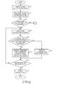
Fig. 17 is a diagram depicting a second portion of the processing flow relating to the embodiment of this invention; -
Fig. 18 is a diagram schematically depicting a flow of the processes in case where the processes are executed serially and the start time recording is carried out; -
Fig. 19 is a diagram schematically depicting a flow of the processes in case where the processes are executed serially and the end time recording is carried out; -
Fig. 20 is a diagram schematically depicting a flow of the processes in case where the processes are executed in parallel and the start time recording is carried out; -
Fig. 21 is a diagram schematically depicting a flow of the processes in case where the processes are executed in parallel and the end time recording is carried out; -
Fig. 22 is a diagram depicting a processing flow of a recording method judging processing; -
Fig. 23 is a diagram schematically depicting the recording method judging processing; -
Fig. 24 is a diagram depicting a processing flow of the recording method judging processing; -
Fig. 25 is a diagram depicting an example of the serial execution of the processes; -
Fig. 26 is a diagram depicting an example of the parallel execution of the processes; -
Fig. 27 is a diagram depicting an example of the parallel execution of the processes; -
Fig. 28 is a diagram depicting an example of a histogram of the processing periods in case where only serial execution of the processes exists; -
Fig. 29 is a diagram depicting an example of the histogram of the processing periods in case where both of the serial execution and parallel execution of the processes; -
Fig. 30 is a diagram depicting a third portion of the processing flow of the embodiment of this invention; -
Fig. 31 is a diagram depicting an example of a case where the parallel execution of the processes is included; -
Fig. 32 is a diagram schematically depicting a processing for identifying the processes executed in parallel; -
Fig. 33 is a diagram depicting an example of the management table; -
Fig. 34 is a diagram depicting a conventional example of the business flow; -
Fig. 35 is a diagram depicting an example of a business flow in case where the embodiment of this invention is carried out; and -
Fig. 36 is a functional block diagram of a computer. -
FIG. 4 depicts a functional block diagram of a businessflow processing apparatus 100 relating to one embodiment of this invention. It is assumed that the business flow processing apparatus 100 is connected to one or plural analysis databases such as databases A and B. In addition, the business flow processing apparatus 100 has a data collector 101 that carries out a processing to collect data from the analysis target databases A and B; a collected data storage 102 that stores the data collected by the data collector 101; a sort processor 103 that carries out a processing to sort the data stored in the collected data storage 102 by using an identifier and processing time; a sort result storage 104 that stores processing results of the processing result; a first overlap extractor 105 that carries out a processing by using data stored in the sort result storage 104; a recording method identifying unit 107 that carries out a processing to identify the recording method by using the data stored in the sort result storage 104; a tentative processing period data storage 108 that stores data during the processing in the recording method identifying unit 107; a second overlap extractor 109 that carries out a processing by using outputs from the recording method identifying unit 107 and the data stored in the sort result storage 104; a processing period data storage 110 that stores data during the processing in the second overlap extractor 109; a management table storage 106 that stores a management table that is a processing result of the first overlap extractor 105 or the second overlap extractor 109; and an output unit 111 that outputs a process instance (that is an example of a business flow) and/or a business flow generated by superimposing the process instances by using the data stored in the sort result storage 104 and the management table stored in the management table storage 106. - Next, processing contents of the business
flow processing apparatus 100 will be explained by usingFigs. 5 to 35 . First, thedata collector 101 carries out a data collection processing to extract transaction records required to generate a business flow from the analysis target databases A and B, and stores the collected record data into the collected data storage 102 (Fig. 5 : step S1). For example, was schematically depicted inFig. 6 , tables a and b are stored in the database A, and transaction records respectively including an identifier, process type and processing time are extracted from the table a, and similarly, transaction records respectively including the identifier, process type and processing time are extracted from the table b. In addition, a table c is stored in the database B, and transaction records respectively including the identifier, process type and processing time are extracted from the table c. Incidentally, when one record in the tables a to c does not include any one of the identifier, process type and processing time, thedata collector 101 carries out a processing to obtain, for example, the process type from the table name, and the like, and generates the transaction records including the identifier, process type and processing time as depicted in the right side ofFig. 6 and stores them into the collecteddata storage 102. Moreover, although an example of one-point recording of the processing time is depicted here, two-point recording that the start time and end time are recorded may be adopted as described below. In such a case, the processing time includes two times. - Next, the
sort processor 103 sorts the transaction records stored in thecolleted data storage 102 by using the identifier and the processing time, and stores the sort results into the sort result storage 104 (step S3). The same identifier means a series of processes for the same case. Therefore, the transaction records are grouped based on the identifier, and by sorting the grouped transaction records based on the processing time, the order of the execution of the respective processes is identified. In an example ofFig. 6 , when the transaction records whose identifier is ID001 and to which a star mark is attached are grouped and arranged in the ascending order of the processing time, data as depicted inFig. 7 is generated and stored into thesort result storage 104. Incidentally, the transaction records whose identifier is other than ID001 is similarly grouped and sorted, and then stored into thesort result storage 104. The group constituted by the grouping at the step S3 is called a process group, hereinafter. - Then, the
first overlap extractor 105 and recordingmethod identifying unit 107 judge, from the data stored in thesort result storage 104, whether or not the two-point recording of the processing time is carried out (step S5). It is judged whether or not the end time and the start time are recorded as the processing time. When it is judged that the one-time recording is carried out, the flow shifts to the processing depicted inFig. 17 through a terminal A, without the processing of thefirst overlap extractor 105. - On the other hand, when the two-point recording of the processing time is carried out, the
first overlap extractor 105 identifies one unprocessed identifiers among the identifiers included in the transaction records stored in the sort result storage 104 (step S7). Then, thefirst overlap extractor 105 judges whether or not the overlap of the processing periods exists in the processes (specifically, transaction records in the same process group) associated with the identified identifier (step S9) - For example, when it is assumed that data as depicted in
Fig. 8 is stored in thesort result storage 104, the start time of the process B is set to be later than the end time of the process A, the start time of the process C is set to be later than the end time of the process B, the start time of the process D is set to be later than the end time of the process C. Therefore, as schematically depicted inFig. 9 , it can be understood that there is no portion executed in parallel during the processes A to D and the processes are serially carried out. - On the other hand, when it is assumed that data as depicted in
Fig. 10 is stored in thesort result storage 104, the start times of the processes B to D are set to be later than the end process A, but the start time of the process B is set to be earlier than the end time of the process B. Incidentally, the start time of the process D is set to be later than the end time of the process B and the end time of the process C. Such a situation is schematically depicted inFig. 11 . As depicted inFig. 11 , it can be understood that a portion (i.e. overlap section) of the processes B and C is carried out in parallel. - Furthermore, when it is assumed that data as depicted in
Fig. 12 is stored in thesort result storage 104, the start times of the process B1 to D are set to be later than the end time of the process A. However, the start time of the process C is set to be earlier than the end time of the process B1, and further the end time of the process C and the start time of the process B2 are set to be later than the end time of the process B1, and the end time of the process C is set to be later than the start time and end time of the process B2. Incidentally, the start time of the process D is set to be later than the end times of the processes A to C. Such a situation is schematically depicted inFig. 13 . As depicted inFig. 13 , although the processes A, B1, B2 and D are serially carried out, it can be understood that the process C is carried out in parallel with a portion (i.e. overlap section) of the processes B1 and B2. The processes B1 and B2 are serially carried out. However, the serially executed processes can be also identified in the portion executed in parallel. - Thus, at the step S9, it is judged, from the start times and end times of the respective transaction records, whether or not the overlap section for the processing periods exists.
- As depicted in
Figs. 8 and 9 , when it is judged that there is no overlap in the processing period, thefirst overlap extractor 105 registers a management table for the currently processed identifier, which represents "no group" into the management table storage 106 (step S11). Specifically, a management table as depicted inFig. 14 is registered. In an example of the management table depicted inFig. 14 , a group code, process types belonging to the group and a combination of non-concurrent processes in the group are registered. Incidentally, because of "no group", no group code is registered, and simply the processes A to D are registered as the process types of the processes, which are serially carried out. In addition, as for the combination of the non-concurrent processes in the group, no data is registered, because of "no group". Incidentally, because of "no group,", the process types belonging to the group may be empty, since the business flow can be drawn by the transaction records stored in thesort result storage 104. - On the other hand, as depicted in
Figs. 10 to 13 , when there is an overlap in the processing period, thefirst overlap extractor 105 stores a management table in a form that the processes whose processing periods overlap are grouped, into the management table storage 106 (step S13). For example, in case ofFigs. 10 and 11 , the processes B and C are grouped, and "no group" is detected for the processes A and D, which are serially carried out. Incidentally, because there is no non-concurrent process in the group, "none" is registered for the combination of the non-concurrent processes in the group. Namely, the management table as depicted inFig. 15 is stored into the management table 106. Furthermore, in case ofFigs. 12 and13 , the processes B1, B2 and C are grouped, and as depicted inFig. 16 , no group is assigned to the processes A and D, which are serially carried out. Incidentally, because the processes, which are serially carried out in the group, are the processes B1 and B2, the processes B1 and B2 are registered to the column of the combination of the non-concurrent processes in the group. Incidentally, because the start time and end time are recorded, it is easy to judge that there is no overlap between the processing periods of the processes B1 and B2. - Then, after the step S13 or S11, the
first overlap extractor 105 judges whether or not all of the identifiers have been processed (step S15). When an unprocessed identifier exists, the processing returns to the step S7. On the other hand, when all of the identifiers have been processed, theoutput unit 111 outputs a business flow (e.g. process instance) to an output device (e.g. display device) by using the data stored in the sort resultsstorage 104 and the management table storage 106 (step S17). For example, the display as depicted inFigs. 2 and/or 3 are made on the display device. - Thus, in case of adopting the two-point recording, it is possible to identify the correct processing period and to correctly judge the parallel execution. Accordingly, the correct business flow can be presented for the user.
- Next, a processing after the terminal A. will be explained by using
Figs. 17 to 35 . When it is judged at the step S5 that the one-time recording was carried out, the recordingmethod identifying unit 107 carries out a recording method fudging processing (Fig. 17 : step S19). The recording method judging processing will be explained by usingFigs. 18 to 24 . Incidentally, when it is possible to apparently identify, from schema information, column name of the database and/or like, which of the start time recording and end time recording was made, such information is effective. When it is unknown from such information, the processing described below is carried out. - Incidentally, when the recording method is unknown from the column names or the like, as depicted in
Figs. 18 to 21 , it is necessary to judge, in case of the one-point recording, which of the start time recording and end time recording was made, in consideration of following cases as depicted inFigs. 18 to 21 , namely, a case (Fig. 18 ) where the start time was recorded and only the serial execution was carried out, a case (Fig. 19 ) where the end time was recorded and only the serial execution was carried out, a case (Fig. 20 ) where the start time was recorded and the parallel execution was included and a case where (Fig. 21 ) where the end time was recorded and the parallel execution was included, even when the transaction records depicted inFig. 7 are stored in thesort result storage 104. - Specifically, as understood from
Fig. 7 , the difference between the processing times of the processes B and C is small. In such a case, as depicted inFigs. 18 and 19 , even when it is assumed that all of the processes are serially executed, the processing period of the process B becomes short in case where the processing time means the start time, and the processing period of the process C becomes short in case where the processing time means the end time. Accordingly, which of cases is applicable influences identification of the portion executed in parallel, which will be explained later. In addition, in case of the parallel execution, as depicted inFigs. 20 and 21 , even if the superficial processing period is short, the actual processing period may not be short. - In this embodiment, under the assumption that (A) the variations of the actual processing periods for each process do not arise so much even when trying the process a lot of times, and even of the variations arises, the distribution of the processing periods follows the normal distribution, (B) the respective processing periods have an inherent periods, and there is some difference between the processes, and (C) a gap between the previous process end and the next process start is small in the extent that it can be disregarded or the gap becomes an inherent value with small discrepancy, it is assumed that the processing times for calculating the processing period were recorded plural time for each process, and a statistic processing as described in the following is carried out. That the processing times for calculating the processing period were recorded plural time for each process means that one kind of processing flow route are executed plural times, plural kinds of processing flow routes including the same process are executed plural times or both of them. Typically, when the number of processing times and/or the number of kinds of routes becomes larger, it is possible, to carry out the more accurate judgment.
- Under the aforementioned assumptions, the recording
method identifying unit 107 identifies one unprocessed process among the processes included in the transaction records stored in the sort result storage 104 (Fig. 22 : step S51). Then, the recordingmethod identifying unit 107 calculates a processing period P using the processing time of the identified process as the start time, and stores the period P into the tentative processing period data storage 108 (step S53). - For example, as depicted in the left side of
Fig. 23 , in case where the processes A, B and C were executed in this order, in case where the processes D, B and E were executed in this order, and in case where the processes C, B and F are executed in this order, we pay attention to the process B now. However, it is assumed that the end time recording is carried out, here. Then, at the step S53, in the left side ofFig. 23 , the processing periods P1, P2 and P3 are calculated and stored into the tentative processingperiod data storage 108. - After that, the recording
method identifying unit 107 calculates a standard deviation of the processing period P (step S55). The variance may be used, not the standard deviation. Any other statistic value representing the dispersion may be used. The standard deviation and/or variance are stored into a storage device such as the tentative processingperiod data storage 108 or main memory. - On the other hand, the recording
method identifying unit 107 calculates a processing period Q using the processing time of the identified transaction as the end time, and stores the period Q into the tentative processing period data storage 108 (step S57). As depicted in the left side ofFig. 23 , the processing periods Q1, Q2 and Q3 are calculated, and stored into the tentative processingperiod data storage 108. - Then, the recording
method identifying unit 107 calculates the standard deviation of the processing period Q (step S59). The variance may be used, not the standard deviation. Any other index representing the dispersion may be used. The standard deviation or variance is also stored into the storage device such as the tentative processingperiod data storage 108 or main memory. - Then, the recording
method identifying unit 107 judges whether or not the standard deviation (or variance) of the processing period Q is greater than the standard deviation (or variance) of the processing period P (step S61) . - As depicted in the right side of
Fig. 23 , this embodiment adopts consideration that the processing period of the actual recording method among the end time recording and the start time recording has small dispersion. As described above, in the example ofFig. 23 , the end time recording is the actual recording method. Therefore, the standard deviation of Q1 to Q3 is less than the standard deviation of P1 to P3. - Therefore, the recording
method identifying unit 107 increments a counter p for the start time recording by one, when the standard deviation (or variance) of the processing period P is less (step S65). On the other hand, when the standard deviation (or variance) of the processing period Q is less or the standard deviation of the processing period P is equal to the processing period Q, the recordingmethod identifying unit 107 increments a counter q for the end time recording by one (step S63). The case where both values are equal may not be counted. - In case of the processes executed in parallel, as depicted in
Figs. 20 and 21 , it is estimated that the variations of the processing periods P and Q arise in some extent, depending on the state of the parallel execution. Therefore, it is difficult to judge which of the start time recording and the end time recording was made, according to one process. Then, the aforementioned processing is carried out for all of the processes to count, by using the counter p for the start time recording, the number of processes whose standard deviation or the like of the processing period in the start time recording is less and also count, by using the counter q for the end time recording, the number of processes whose standard deviation or the like of the processing period in the end time recording is less. - After the step S63 or S65, the recording
method identifying unit 107 judges whether or not all of the processes have been processed (step S67). When an unprocessed process exists, the flow returns to the step S51. When no unprocessed process exists, the flow shifts to a processing ofFig. 24 through a terminal D. - Shifting to the explanation of the processing of
Fig. 24 , the recordingmethod identifying unit 107 judges whether or not the value of the counter p is greater than the value of the counter q (steep S69). When the value of the counter p is greater than the value of the counter q, the recordingmethod identifying unit 107 sets the start, time recording to the second overlap extractor 109 (step S71). On the other hand, when it cannot be said that the value of counter p is greater than the value of the counter q, the recording,method identifying unit 107 sets the end time recording to the second overlap extractor 109 (step S73). Then, the flow returns to the calling source processing. - Returning to the explanation of
Fig. 17 , thesecond overlap extractor 109 judges whether or not the start time recording is set (step S21). When the start time recording is set, thesecond overlap extractor 109 calculates the processing periods of the respective transaction records stored in thesort result storage 104 according to ((start time of the process immediately after a target process) - (start time of the target process)) by using data stored in the transaction records stored in thesort result storage 104, and stores the calculation result into the processing period data storage 110 (step S23). For example, the calculated processing period is stored in association with the identifier included in the transaction record and the process type. On the other hand, when the end time recording is set, thesecond overlap extractor 109 calculates the processing periods of the respective transaction records stored in thesort result storage 104 according to ((end time of the target process) - (end time of the process immediately before the target process)) by using data of the transaction records stored in thesort result storage 104, and stores the calculation result into the processing period data storage 110 (step S25). For example, the calculated processing period is stored in association with the identifier included in the transaction record and the process type. - When the step S23 or S25 has been carried out, preparation of a processing to identify portions executed in parallel has been completed. In the following processing, under the assumption that (A) the variations of the actual processing periods for each process do not arise so much even when trying the process a lot of times, and even if the variations arises, the distribution of the processing periods follows the normal distribution, (B) the respective processing periods have an inherent processing period, and there is some difference between the processing periods, and (C) a gap between the previous process end and the next process start is small in the extent that it can be disregarded or the gap becomes an inherent value with small discrepancy, it is assumed that the processing times for calculating the processing period were recorded plural times for each process, and a statistic processing as described in the following is carried out. That the processing times for calculating the processing period were recorded plural time for each process means that one kind of processing flow route are executed plural times or plural kinds of processing flew routes including the same process are executed plural times or both of them. Typically, when the number of processing times and/or the number of kinds of routes becomes larger, it is possible to carry out the more accurate judgment.
- First, the
second overlap extractor 109 identifies one unprocessed process among the processes included in the transaction records stored in thesort result storage 104 or data stored in the processing period data storage 110 (step S27). Then, thesecond overlap extractor 109 generates a histogram of the processing periods for the identified process (step S29). - For example, as depicted in
Fig. 25 , when the processes E, C and F are serially executed (in case of the end time recording), the processing period of the process C becomes long. However, as depicted inFig. 26 , when the processes B and C are executed in parallel, the superficial processing period of the process C may be much shorter. Furthermore, as depicted inFig. 27 , although the processes B and C are executed in parallel in the same manner, the superficial processing period of the process C may become short or long, depending on the fluctuation of the processing periods. Therefore, by generating the histogram of the processing period for the same process at the step S29, a peak statistically occurs at the processing period in case of the serial execution, and one or plural peaks occur at the superficial processing periods at the parallel execution in case of the parallel execution. In case of the process, which is executed only serially, one peak is detected as depicted inFig. 28 . The processing period of this peak is presumed to be actual processing period. In addition, when both of the parallel execution and serial execution are carried out, plural peaks are detected as depicted inFig. 29 . The processing period in case of the serial execution is always longer than the superficial processing period at the parallel execution. Therefore, in this embodiment, when plural peaks appear, the processing period of the peak whose processing period is the longest is presumed to be actual processing period. - Then, the second overlap extractor 209 judges whether or not any peak is detected in the histogram generated at the step S29 (step S31) . The condition to detect the rise as the peak depends on the frequency of the execution of the process. Therefore, the condition is appropriately set. When no peak is detected, the actual processing period cannot be identified. Therefore, the
second overlap extractor 109 registers "indefinite" for the identified process into the management table for all of the process groups to which the identified process belongs (step S33). Then, the flow shifts to step S27 through a terminal C. - On the other hand, when the peak is detected, the
second overlap extractor 109 judges whether or not the peak is single (step S35). When the peak is single, the process is executed only serially, as described above. Therefore, thesecond overlap extractor 109 registers "no grouping" for the identified process into the management table for all process groups to which the identified process belongs (step S37). Then, the flow shifts to a processing ofFig. 30 through a terminal B. - On the other hand, when plural peaks are detected, as described above, the
second overlap extractor 109 sets the processing period of the peak whose processing period is the longest among the processing periods of the plural peaks as the processing period of the process identified at the step S27 (step S29). For example, the processing period of the identified process is stored into the storage device such as the main memory. Then, thesecond overlap extractor 109 identifies portions (specifically, process group including a specific process whose processing period is shorter than the set processing period and the specific process) of the processing periods, which are shorter than the set processing period, as the portion executed in parallel (step S41). For example, the specific process is stored in association with the management table of the pertinent group into themanagement table storage 106. Incidentally, this step may be skipped, and all of the processes for which plural peaks are detected may be treated as the portions executed in parallel. Then, the flow shifts to the processing ofFig. 30 through the terminal B. - Shifting to explanation of the processing of
Fig. 30 , thesecond overlap extractor 109 judges whether or not all of the processes have been processed (step S81). When an unprocessed process exists, the flow returns to the step S27 through a terminal C. On the other hand, when all of the processes have been processed, thesecond overlap extractor 109 one unprocessed identifier among the identifiers included in the transaction records stored in the sort result storage 104 (step S83). Then, thesecond overlap extractor 109 judges whether or not the portion executed in parallel is registered for the identified identifier (i.e. process group) (step S85). In case of only "no group", the management table has been completed as depicted inFig. 4 by repeating the step S37. Therefore, the flow shifts to step S93. - On the other hand, when the portion executed, in parallel is registered, the
second overlap extractor 109 identifies, for each portion executed in parallel, a process executed in parallel based on the processing periods (step S89). Here, a case ofFig. 31 is assumed. In an example ofFig. 31 , the end time recording is adopted. As apparent fromFig. 31 , it is assumed that the process C is identified as the portion executed in parallel, and actually the processes E, B1 and B2 are executed, in parallel. Incidentally, as depicted in the lower portion ofFig 31 , the processing period, which is calculated at the step S25 and stored in the processingperiod data storage 110, is "A" for the process A, "B1" for the process B1, "E" for the process E, "B2" for the process B2, "C" for the process C and "D" for the process D. However, because the processes B1, B2, C and E are executed in parallel, the correct processing periods are not calculated. - Therefore, a start time of the process C, which is a process identified as the portion executed in parallel (in case of the end time recording. However, in case of the start time recording, the end time recording is applicable.), is calculated. When the end time of the process C is denoted as Cend and the processing period set for the process C at the step S39 as the actual processing period is denoted as Ct, (Cend - Ct) is calculated as depicted in
Fig. 32 (in case of the start time recording, the start time is denoted as Cstart, the end time is calculated by (Cstart + Ct)). Therefore, the process whose end time is recorded within a range from the start time (Cend - Ct) to the end time Cend is a process executed in parallel with the process C. Then, as apparent fromFigs. 31 and 32 , the processes E, B1 and B2 are executed in parallel. Incidentally, in case of the start time recording, the process whose start time is recorded within a range from Cstart to (Cstart + Ct) is process executed in parallel. - Thus, the
second overlap extractor 109 registers the management table in a form that the processes executed in parallel are grouped, into the management table 106 (step S91). For example, in the example ofFigs. 31 and 32 , the table as depicted inFig. 33 is registered. The group includes the processes C, B1, B2 and E. - Incidentally, when paying attention to the process C, the processes executed in parallel are the processes B1, B2 and E. However, when paying attention to the process B1, the processes executed in parallel are only the processes E and C, when paying attention to the process B2, they are only the processes E and C, and when paying attention to the process E, they are the processes B1, B2 and C. Thus, when simply paying attention to the individual processes of the portions executed in parallel, groups of the processes executed in parallel are different. However, because it is necessary to identify a group including the parallel execution, by a unit of the process group, which is based on the identifier, the groups of the processes executed in parallel are unified when the included processes overlap. Namely, the processes C, B1, B2 and E are grouped after the unification. Furthermore, when paying attention to the process B1, the process B2 is not included, and when paying attention to the process B2, the process B1 is not included. Therefore, it is determined that the processes B1 and B2 are serially carried out. Therefore, the processes B1 and B2 are identified as a combination of the non-concurrent processes in the group. Thus, when identifying the combination of the non-concurrent processes in the group, the start time and end time may be identified by using the actual processing period stored, for example, in the processing
period data storage 110, and it may be checked whether or not there is no overlap. - As described above, a group of the processes executed in parallel in the group, which is based on the identifier, is identified and registered at the step S91, and further the combination of the non-concurrent processes in the group is also identified and registered.
- Then, when it is judged at the step S85 that there is no portion executed in parallel or after the step S91, the
second overlap extractor 109 judges whether or not all of the identifiers have been processed (step S93). When an unprocessed identifier exists, the flow returns to the step S83. - On the other hand, when all of the identifiers have been processed, the
output unit 111 outputs a business flow (here, process instance) by using data stored in thesort result storage 104 and the management table storage 106 (step S95). For example, the display as depicted inFigs. 2 and3 are carried out on the display device. - At the step S17 or S95, the business flow, which is generated by summarizing the process instances, may be output. Namely, the business flow is generated by superimposing the process instances to present the business flow.
- For example, when the serial execution is inaccurately recognized, there is possibility that various different process instances such as A-B1-B2-C-E-D, A-B1-C-B2-E-D, A-C-E-B1-B2-D and the like may be recognized, and by superimposing those process instances, a business flow in which the process instances are complicated may be generated. However, when the management table as depicted in
Fig. 33 is generated, as depicted inFig. 35 , a business flow can be presented in which the processes A and D are executed serially, the processes C, E, B1 and B2 are executed in parallel, and the processes B1 and B2 among them are executed serially. - Although the embodiment of this invention was explained above, this invention is not limited to this. For example, the functional block diagram depicted in
Fig. 4 is a mere example, and there is a case where it does not correspond to the program module configuration. In addiction, the explanation was made under the assumption, that the businessflow processing apparatus 100 is implemented one computer. However, the processing may be allocated to plural computers. In addition, the processing flew may be changed, as long as the same result can be obtained. - In addition, the business
flow processing apparatus 100 is a computer device as shown inFIG. 36 . That is, a memory 2501 (storage device), a CPU 2503 (processor), a hard disk drive (HDD) 2505, adisplay controller 2507 connected to adisplay device 2509, adrive device 2513 for aremovable disk 2511, aninput device 2515, and acommunication controller 2517 for connection with a network are connected through abus 2519 as shown inFIG. 36 . An operating system (OS) and an application program for carrying out the foregoing processing in the embodiment, are stored in theHDD 2505, and when executed by theCPU 2503, they are read out from theHDD 2505 to thememory 2501. As the need arises, theCPU 2503 controls thedisplay controller 2507, thecommunication controller 2517, and thedrive device 2513, and causes them to perform necessary operations. Besides, intermediate processing data is stored in thememory 2501, and if necessary, it is stored in theHDD 2505. In this embodiment of this invention, the application program to realize the aforementioned functions is stored in theremovable disk 2511 and distributed, and then it is installed into theHDD 2505 from thedrive device 2513. It may be installed into theHDD 2505 via the network such as the Internet and thecommunication controller 2517. In the computer as stated above, the hardware such as theCPU 2503 and thememory 2501, the OS and the necessary application programs systematically cooperate with each other, so that various functions as described above in details are realized.
Claims (6)
- A business flow processing program for causing a computer to execute a procedure comprising:obtaining transaction records including a processing time, a process type and an identifier from a database;grouping said transaction records based on said identifier, and sorting said transaction records in each group based on said processing time;calculating a processing period for each said transaction record, based on a sequence of said processing times in said transaction records within said group, in case where said processing time included in said transaction record represents only one time;first identifying transaction records relating to a process carried out in parallel based on distribution, for each said process type, of the calculated processing periods; andsecond identifying, for each said group, a business flow of the group from processing results of the first identifying and said transaction records within the group.
- The business flow processing program as set forth in claim 1, wherein said calculating comprises:calculating a first tentative processing period for each said transaction record in case where said processing time is a start time, and a second tentative processing period for each said transaction record in case where said processing time is an end time;calculating, for each said process type, an index value representing dispersion of the first tentative processing periods and an index value representing dispersion of the second tentative processing periods; andstatistically judging, for each said process type, said processing time indicates either of said start time and said end time, by comparing said index value representing said dispersion of said first tentative processing periods with said index value representing said dispersion of said tentative processing periods.
- The business flow processing program as set forth in claim 1, wherein said first identifying comprises:judging, for each said process type, whether or not a plurality of peaks appear in said distribution of the calculated processing periods, and identifying a process type for which said plurality of peaks appear, as a process type carried out in parallel;identifying, for said process carried out in parallel, said processing period for a peak whose processing period is longest among said plurality of peaks, as a deemed processing period; andjudging, for each of said transaction record, whether or not the transaction record is a transaction record relating to said process carried out in parallel by using said processing time for the transaction record, said deemed processing period and said processing times of other transaction records in the group of the transaction record.
- The business flow processing program as set forth in claim 1, wherein said procedure further comprises:third identifying, for each said group, transaction records relating to a process carried out in parallel based on an end time and a start time, which are included in said transaction records, in case where said processing time included in said transaction records includes said end time and said start time; andidentifying, for each said group, a business flow of the group, based on processing result of said third identifying and said transaction records in the group.
- A business flow processing method, comprising:obtaining transaction records including a processing time, a process type and an identifier from a database;grouping said transaction records based on said identifier, and sorting said transaction records in each group based on said processing time;calculating a processing period for each said transaction record, based on a sequence of said processing times in said transaction records within said group, in case where said processing time included in said transaction record represents only one time;first identifying transaction records relating to a process carried out in parallel based on distribution, for each said process type, of the calculated processing periods; andsecond identifying, for each said group, a business flow of the group from processing results of the first identifying and said transaction records within the group.
- A business flow processing apparatus, comprising:means for obtaining transaction records including a processing time, a process type and an identifier from a database;means for grouping said transaction records based on said identifier, and sorting said transaction records in each group based on said processing time;means for calculating a processing period for each said transaction record, based on a sequence of said processing times in said transaction records within said group, in case where said processing time included in said transaction record represents only one time;first identifying means for identifying transaction records relating to a process carried out in parallel based on distribution, for each said process type, of the calculated processing periods; andsecond identifying means for identifying, for each said group, a business flow of the group from processing results by the first identifying means and said transaction records within the group.
Applications Claiming Priority (1)
| Application Number | Priority Date | Filing Date | Title |
|---|---|---|---|
| PCT/JP2008/052030 WO2009098766A1 (en) | 2008-02-07 | 2008-02-07 | Work flow processing program, work flow processing method and work flow processor |
Publications (2)
| Publication Number | Publication Date |
|---|---|
| EP2249293A1 true EP2249293A1 (en) | 2010-11-10 |
| EP2249293A4 EP2249293A4 (en) | 2012-11-21 |
Family
ID=40951854
Family Applications (1)
| Application Number | Title | Priority Date | Filing Date |
|---|---|---|---|
| EP08710910A Ceased EP2249293A4 (en) | 2008-02-07 | 2008-02-07 | WORKFLOW PROCESSING PROGRAM, WORKFLOW PROCESSING METHOD, AND WORKFLOW PROCESSOR |
Country Status (4)
| Country | Link |
|---|---|
| US (2) | US8713070B2 (en) |
| EP (1) | EP2249293A4 (en) |
| JP (1) | JP4973738B2 (en) |
| WO (1) | WO2009098766A1 (en) |
Families Citing this family (5)
| Publication number | Priority date | Publication date | Assignee | Title |
|---|---|---|---|---|
| US10404526B2 (en) * | 2016-09-20 | 2019-09-03 | Conduent Business Services, Llc | Method and system for generating recommendations associated with client process execution in an organization |
| US10235105B1 (en) | 2018-02-27 | 2019-03-19 | Ricoh Company, Ltd. | Microservice architecture workflow management mechanism |
| CN111275373B (en) * | 2018-12-05 | 2024-05-21 | 北京京东乾石科技有限公司 | Efficiency acquisition method, system and equipment of elevator and readable storage medium |
| US11544068B2 (en) * | 2019-09-26 | 2023-01-03 | Visier Solutions, Inc. | Systems and methods for generating a pipeline of stages for a process |
| CN113903128B (en) * | 2021-12-09 | 2022-03-15 | 武汉天喻信息产业股份有限公司 | Equipment with display and method for improving running performance of equipment with display |
Family Cites Families (40)
| Publication number | Priority date | Publication date | Assignee | Title |
|---|---|---|---|---|
| US4965763A (en) | 1987-03-03 | 1990-10-23 | International Business Machines Corporation | Computer method for automatic extraction of commonly specified information from business correspondence |
| DE69811790T2 (en) * | 1997-08-01 | 2003-11-20 | International Business Machines Corp., Armonk | Deriving process models from audit processes for workflow management systems |
| US6038538A (en) * | 1997-09-15 | 2000-03-14 | International Business Machines Corporation | Generating process models from workflow logs |
| DE19954268B4 (en) * | 1998-12-01 | 2005-07-21 | Ibm Corp. | Method and system for improving workflow in workflow management systems |
| US6457014B1 (en) | 1999-03-26 | 2002-09-24 | Computer Associates Think, Inc. | System and method for extracting index key data fields |
| JP3609333B2 (en) * | 2000-09-29 | 2005-01-12 | 株式会社リコー | Sales management method, sales management system, and recording medium |
| US20030065702A1 (en) * | 2001-09-24 | 2003-04-03 | Ravinder Singh | Cache conscious load balancing |
| US7562339B2 (en) * | 2002-01-15 | 2009-07-14 | Bea Systems, Inc. | System architecture for business process development and execution with introspection and generic components |
| JP2003256627A (en) * | 2002-02-27 | 2003-09-12 | Hitachi Ltd | Workflow extraction method and apparatus |
| US7571187B2 (en) * | 2002-05-31 | 2009-08-04 | Microsoft Corporation | Support for real-time queries concerning current state, data and history of a process |
| US7565304B2 (en) * | 2002-06-21 | 2009-07-21 | Hewlett-Packard Development Company, L.P. | Business processes based on a predictive model |
| US7610211B2 (en) * | 2002-06-21 | 2009-10-27 | Hewlett-Packard Development Company, L.P. | Investigating business processes |
| US7398525B2 (en) * | 2002-10-21 | 2008-07-08 | International Business Machines Corporation | Resource scheduling in workflow management systems |
| US8332864B2 (en) * | 2003-06-12 | 2012-12-11 | Reuters America Inc. | Business process automation |
| JP4287234B2 (en) * | 2003-10-03 | 2009-07-01 | 富士通株式会社 | Business process tracking device, business process tracking method, business process tracking program, and recording medium recording the business process tracking program |
| JP2005173847A (en) | 2003-12-10 | 2005-06-30 | Fujitsu Ltd | Information search apparatus, information search method, program, and recording medium recording the program |
| JP4625337B2 (en) * | 2004-02-23 | 2011-02-02 | 株式会社リコー | Process management apparatus, process management method, and process management program |
| US20070203589A1 (en) * | 2005-04-08 | 2007-08-30 | Manyworlds, Inc. | Adaptive Recombinant Process Methods |
| JP2006031326A (en) | 2004-07-15 | 2006-02-02 | Mitsubishi Electric Corp | Information processing apparatus, information processing method, and program |
| US7712102B2 (en) * | 2004-07-30 | 2010-05-04 | Hewlett-Packard Development Company, L.P. | System and method for dynamically configuring a plurality of load balancers in response to the analyzed performance data |
| US8010337B2 (en) * | 2004-09-22 | 2011-08-30 | Microsoft Corporation | Predicting database system performance |
| JP2006134106A (en) | 2004-11-05 | 2006-05-25 | Hammock:Kk | Form recognition system, form recognition method, and computer program |
| GB0427133D0 (en) * | 2004-12-10 | 2005-01-12 | British Telecomm | Workflow scheduler |
| JP2006197294A (en) | 2005-01-14 | 2006-07-27 | Epson Toyocom Corp | Symmetric inverter vs. piezoelectric oscillator |
| JP4444867B2 (en) | 2005-03-31 | 2010-03-31 | 富士通株式会社 | Business process model creation support system and program, and business process model creation processing method |
| JP4549231B2 (en) * | 2005-05-17 | 2010-09-22 | 富士通株式会社 | Service processing status analysis program, service processing status analysis method, and service processing status analysis device |
| US20070055558A1 (en) * | 2005-08-19 | 2007-03-08 | Shanahan James G | Method and apparatus for probabilistic workflow mining |
| US7739099B2 (en) * | 2005-12-22 | 2010-06-15 | International Business Machines Corporation | Method and system for on-line performance modeling using inference for real production IT systems |
| KR101214195B1 (en) * | 2005-12-28 | 2012-12-24 | 텔레콤 이탈리아 소시에떼 퍼 아찌오니 | A method for the automatic generation of workflow models, in particular for interventions in a telecommunication network |
| JP4839088B2 (en) * | 2006-01-11 | 2011-12-14 | 株式会社リコー | Workflow management system |
| US20070189509A1 (en) * | 2006-02-13 | 2007-08-16 | Foody Daniel M | Data path identification and analysis for distributed applications |
| US8752030B1 (en) * | 2006-03-09 | 2014-06-10 | Verizon Services Corp. | Process abstraction and tracking, systems and methods |
| JP4904878B2 (en) * | 2006-03-27 | 2012-03-28 | 富士通株式会社 | System development support program, system development support device, and system development support method |
| JP2007279861A (en) * | 2006-04-04 | 2007-10-25 | Mitsubishi Electric Corp | Business process management apparatus, business process management method, and business process management program |
| WO2007132547A1 (en) | 2006-05-16 | 2007-11-22 | Fujitsu Limited | Job model generation program, job model generation method, and job model generation device |
| JP4997856B2 (en) | 2006-07-19 | 2012-08-08 | 富士通株式会社 | Database analysis program, database analysis apparatus, and database analysis method |
| US20080065448A1 (en) * | 2006-09-08 | 2008-03-13 | Clairvoyance Corporation | Methods and apparatus for identifying workflow graphs using an iterative analysis of empirical data |
| US20090037242A1 (en) * | 2007-07-30 | 2009-02-05 | Siemens Medical Solutions Usa, Inc. | System for Monitoring Periodic Processing of Business Related Data |
| US20090094074A1 (en) * | 2007-10-04 | 2009-04-09 | Nikovski Daniel N | Method for Constructing Business Process Models from Task Execution Traces |
| US7912946B2 (en) * | 2008-01-25 | 2011-03-22 | International Business Machines Corporation | Method using footprints in system log files for monitoring transaction instances in real-time network |
-
2008
- 2008-02-07 EP EP08710910A patent/EP2249293A4/en not_active Ceased
- 2008-02-07 JP JP2009552354A patent/JP4973738B2/en not_active Expired - Fee Related
- 2008-02-07 WO PCT/JP2008/052030 patent/WO2009098766A1/en not_active Ceased
-
2010
- 2010-08-02 US US12/848,526 patent/US8713070B2/en active Active
-
2014
- 2014-03-06 US US14/198,991 patent/US20140188547A1/en not_active Abandoned
Also Published As
| Publication number | Publication date |
|---|---|
| US20140188547A1 (en) | 2014-07-03 |
| US8713070B2 (en) | 2014-04-29 |
| EP2249293A4 (en) | 2012-11-21 |
| JP4973738B2 (en) | 2012-07-11 |
| JPWO2009098766A1 (en) | 2011-05-26 |
| WO2009098766A1 (en) | 2009-08-13 |
| US20100299373A1 (en) | 2010-11-25 |
Similar Documents
| Publication | Publication Date | Title |
|---|---|---|
| US6801938B1 (en) | Segmentation and processing of continuous data streams using transactional semantics | |
| US8671084B2 (en) | Updating a data warehouse schema based on changes in an observation model | |
| US20060074621A1 (en) | Apparatus and method for prioritized grouping of data representing events | |
| US20080270403A1 (en) | Segmentation and processing of continuous data streams using transactional semantics | |
| EP2124176A1 (en) | Task analysis program and task analyzer | |
| US20040024627A1 (en) | Method and system for delivery of infrastructure components as they related to business processes | |
| EP2759938A1 (en) | Operations management device, operations management method, and program | |
| CN109934268B (en) | Abnormal transaction detection method and system | |
| US20140188547A1 (en) | Business flow processing method and apparatus | |
| Swinnen et al. | A process deviation analysis–a case study | |
| CN107291745B (en) | Data index management method and device | |
| US20110106577A1 (en) | Business flow analysis method and apparatus | |
| CN104636211A (en) | Information interaction method among software systems, and middleware system | |
| US11657063B2 (en) | Behavioral analytics in information technology infrasturcture incident management systems | |
| CN113138906A (en) | Call chain data acquisition method, device, equipment and storage medium | |
| JP5746565B2 (en) | Maintenance management system, work priority calculation method and program | |
| CN118627694A (en) | Process optimization method and system based on clothing and apparel preparation | |
| JP2009134535A (en) | Software development support apparatus, software development support method, and software development support program | |
| CN116090789B (en) | Lean manufacturing production management system and method based on data analysis | |
| CN113011986B (en) | Insurance calculation abstract method and system | |
| CN113705859B (en) | Method and device for predicting influence value of deviation cause, electronic equipment and storage medium | |
| CN114116729B (en) | Test data processing method and equipment | |
| CN121599599A (en) | A method and system for intelligent management of the entire life cycle of ultra-high voltage metering equipment | |
| CN118096387A (en) | Data asset management method, device, equipment and medium | |
| WO2019012674A1 (en) | Program integration/analysis/management device, and integration/analysis/management method therefor |
Legal Events
| Date | Code | Title | Description |
|---|---|---|---|
| PUAI | Public reference made under article 153(3) epc to a published international application that has entered the european phase |
Free format text: ORIGINAL CODE: 0009012 |
|
| 17P | Request for examination filed |
Effective date: 20100902 |
|
| AK | Designated contracting states |
Kind code of ref document: A1 Designated state(s): AT BE BG CH CY CZ DE DK EE ES FI FR GB GR HR HU IE IS IT LI LT LU LV MC MT NL NO PL PT RO SE SI SK TR |
|
| AX | Request for extension of the european patent |
Extension state: AL BA MK RS |
|
| DAX | Request for extension of the european patent (deleted) | ||
| A4 | Supplementary search report drawn up and despatched |
Effective date: 20121019 |
|
| RIC1 | Information provided on ipc code assigned before grant |
Ipc: G06Q 10/06 20120101ALI20121015BHEP Ipc: G06Q 10/04 20120101AFI20121015BHEP |
|
| 17Q | First examination report despatched |
Effective date: 20140103 |
|
| REG | Reference to a national code |
Ref country code: DE Ref legal event code: R003 |
|
| STAA | Information on the status of an ep patent application or granted ep patent |
Free format text: STATUS: THE APPLICATION HAS BEEN REFUSED |
|
| 18R | Application refused |
Effective date: 20171203 |