EP2249232B1 - Cursor control device - Google Patents
Cursor control device Download PDFInfo
- Publication number
- EP2249232B1 EP2249232B1 EP10001120.4A EP10001120A EP2249232B1 EP 2249232 B1 EP2249232 B1 EP 2249232B1 EP 10001120 A EP10001120 A EP 10001120A EP 2249232 B1 EP2249232 B1 EP 2249232B1
- Authority
- EP
- European Patent Office
- Prior art keywords
- holder
- circuit module
- shell
- control device
- sleeve
- Prior art date
- Legal status (The legal status is an assumption and is not a legal conclusion. Google has not performed a legal analysis and makes no representation as to the accuracy of the status listed.)
- Active
Links
Images


Classifications
-
- G—PHYSICS
- G06—COMPUTING; CALCULATING OR COUNTING
- G06F—ELECTRIC DIGITAL DATA PROCESSING
- G06F3/00—Input arrangements for transferring data to be processed into a form capable of being handled by the computer; Output arrangements for transferring data from processing unit to output unit, e.g. interface arrangements
- G06F3/01—Input arrangements or combined input and output arrangements for interaction between user and computer
- G06F3/03—Arrangements for converting the position or the displacement of a member into a coded form
- G06F3/033—Pointing devices displaced or positioned by the user, e.g. mice, trackballs, pens or joysticks; Accessories therefor
- G06F3/0354—Pointing devices displaced or positioned by the user, e.g. mice, trackballs, pens or joysticks; Accessories therefor with detection of 2D relative movements between the device, or an operating part thereof, and a plane or surface, e.g. 2D mice, trackballs, pens or pucks
-
- G—PHYSICS
- G06—COMPUTING; CALCULATING OR COUNTING
- G06F—ELECTRIC DIGITAL DATA PROCESSING
- G06F3/00—Input arrangements for transferring data to be processed into a form capable of being handled by the computer; Output arrangements for transferring data from processing unit to output unit, e.g. interface arrangements
- G06F3/01—Input arrangements or combined input and output arrangements for interaction between user and computer
- G06F3/03—Arrangements for converting the position or the displacement of a member into a coded form
- G06F3/033—Pointing devices displaced or positioned by the user, e.g. mice, trackballs, pens or joysticks; Accessories therefor
- G06F3/0338—Pointing devices displaced or positioned by the user, e.g. mice, trackballs, pens or joysticks; Accessories therefor with detection of limited linear or angular displacement of an operating part of the device from a neutral position, e.g. isotonic or isometric joysticks
-
- G—PHYSICS
- G06—COMPUTING; CALCULATING OR COUNTING
- G06F—ELECTRIC DIGITAL DATA PROCESSING
- G06F3/00—Input arrangements for transferring data to be processed into a form capable of being handled by the computer; Output arrangements for transferring data from processing unit to output unit, e.g. interface arrangements
- G06F3/01—Input arrangements or combined input and output arrangements for interaction between user and computer
- G06F3/03—Arrangements for converting the position or the displacement of a member into a coded form
- G06F3/041—Digitisers, e.g. for touch screens or touch pads, characterised by the transducing means
- G06F3/042—Digitisers, e.g. for touch screens or touch pads, characterised by the transducing means by opto-electronic means
Definitions
- the present invention relates to cursor control technology and more particularly, to a cursor control device formed of a hollow elongated circular module holder, a sleeve sleeved onto the circular module holder and axially slidable and transversely rotatable by the user and a circuit module mounted in the circular module holder for sensing the direction and movement of the sleeve and outputting a control signal to control a cursor on a display screen of an external electronic device.
- a computer has multiple functions, bringing convenience to the user.
- a computer may be equipped with a keyboard and/or mouse for controlling a cursor on a display screen.
- a user may rest the wrist of the hand on the desk or a mouse pad and then move the computer mouse or click the button of the computer mouse with the fingers.
- the user when going to move the computer mouse over a big area, the user must lift the wrist from the desk or mouse pad. Excessive or improper use of a computer may cause pain in the wrist (the so-called carpal tunnel syndrome).
- wrist rests are created.
- a wrist rest is a device used to support the wrist while typing or when using a computer mouse.
- the present invention has been accomplished under the circumstances in view. It is one object of the present invention to provide a cursor control device, which is orthopedically engineered for comfortable use to control a cursor on a display screen of an electronic device. It is another object of the present invention to provide a cursor control device, which produces less friction during operation, assuring operating stability.
- the cursor control device comprises a hollow elongated circuit module holder having a top opening, a sleeve sleeved onto the circuit module holder and movable leftwards and rightwards and rotatable forwards and backwards relative to the circuit module without friction and a circuit module accommodated in the circuit module holder and adapted for sensing the direction and amount of movement of the sleeve relative to the circuit module holder and producing a signal indicative of the direction and amount of movement of the sleeve relative to the circuit module holder for controlling a cursor on a display screen of an electronic device to grab a web page and to scroll up or down the web page or to click a menu selection.
- the circuit module comprises a control switch, which produces a triggering signal when the user presses the sleeve.
- circuit module holder is made from a self-lubricating material, facilitating movement of the sleeve. Therefore, the sleeve can be moved smoothly relative to the circular module holder without causing much friction resistance.
- the circuit module holder is formed of a first holder shell and a second holder shell. Further, the circuit module is accommodated in the second holder shell and affixed to the second holder shell. Because the circuit module is protected inside the circular module holder and does not require any extra installation space in the electronic device, the cursor control device has an integrated outer appearance and a small-size characteristic.
- a cursor control device in accordance with the present invention is shown comprising a circuit module holder 1, a circuit module 2, a sleeve 3 and a housing 4.
- the circuit module holder 1 comprises a first holder shell 11 and a second holder shell 12.
- the first holder shell 11 and the second holder shell 12 define there between an accommodation space 10.
- the first holder shell 11 has a plurality of limiters 111 symmetrically disposed, for example, near two distal ends thereof at two opposite lateral sides relative to the accommodation space 10 and a plurality of locating members 112 symmetrically located on the two distal ends.
- the second holder shell 12 has an opening 121 cut through the top and bottom walls thereof in communication with the accommodation space 10, a plurality of mounting portions 122 protruded from the bottom wall and a plurality of stop members 123 corresponding to the limiters 111 of the first holder shell 11. Further, elastic members 124 are respectively fastened to the bottom wall of the second holder shell 12 and stopped against the first holder shell 11 to support the second holder shell 12 above the first holder shell 11.
- the circuit module 2 is accommodated in the accommodation space 10 in the circuit module holder 1, comprising a circuit board 20 carrying a microprocessor 21, a sensor module 22, a control switch 23 and a transmission interface 24.
- the circuit board 20 has a plurality of mounting portions 25 respectively fixedly fastened to the mounting portions 122 of the second holder shell 12 of the circuit module holder 1.
- the sensor module 22, the control switch 23 and the transmission interface 24 are respectively electrically connected to the microprocessor 21.
- the sensor module 22 is disposed corresponding to the opening 121 of the second holder shell 12 of the circuit module holder 1 for detecting the direction and amount of movement of the sleeve 3 relative to the circuit module holder 1.
- the transmission interface 24 is adapted for communication with communication interface means of an external computer (not shown).
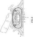
- the sensor module 22 comprises a substrate 222, a light source 223 mounted in the substrate 222, a lens 224 molded on the substrate 222 over the light source 223 and inserted into the opening 121 of the second holder shell 12 of the circuit module holder 1 in flush with the top wall of the second holder shell 12 (see FIG. 6 ) and a sensor 221 installed in the substrate 222 for sensing reflected light from the sleeve 3 upon radiation of the light emitted by the light source 223 through the lens 224.
- the sleeve 3 defines an axial hole 31.
- the sleeve 3 is mounted around the circuit module holder 1 and can be moved axially back and forth relative to the circuit module holder 1 and rotated around the circuit module holder 1.
- the housing 4 comprises a bottom shell 41 and at least one, for example, two top cover shells 42.
- the two top cover shells 42 are covered on the top side of the bottom shell 41 such that an accommodation chamber 40 is defined in between the bottom shell 41 and the top cover shells 42 for accommodating the assembly of the sleeve 3, the circuit module holder 1 and the circuit module 2.
- the bottom shell 41 has a plurality of male hook members (or female hook members) 411 symmetrically disposed at two opposite lateral sides, a plurality of locating members 412 symmetrically disposed near two distal ends thereof and respectively fastened to the locating members 112 of the first holder shell 11 by fastening members 413, two protruding blocks 414 respectively located on the two distal ends.
- an open space 421 is defined between the two top cover shells 42 corresponding to the opening 121 of the second holder shell 12 of the circuit module holder 1.
- the two top cover shells 42 have a substantially -shaped cross section.
- each top cover shell 42 has a plurality of female hook members (or male hook members) 422 respectively fastened to the male hook members (or female hook members) 411 of the bottom shell 41 and a locating groove 423 coupled to one of the two protruding blocks 414 of the bottom shell 41.
- the circuit module holder 1 is formed of the first holder shell 11 and the second holder shell 12.
- the circuit module holder 1 can be a single-piece hollow bar having a circular or oval cross section allowing rotation and reciprocating displacement of the sleeve 3 therein.
- the circuit module holder 1 can be made from polyoxymetylene (POM), polytetrafluoroethylene (PTFE), ultra high molecular weight polyethylene (UHMWPE) or any of a variety of other suitable self-lubricating materials.
- the sensor module 22 of the circuit module 2 detects the direction and amount of movement of the sleeve 3 in such a manner that the light source 223 emits light through the lens 224 onto the sleeve 3.
- the surface characteristic (such as color, raised portions, recessed portions, smoothness) of the radiated part of the sleeve 3 interferes with light, causing a reflected light having a different characteristic to be produced.
- the sensor 221 senses the reflected light from the sleeve 3 and provides a corresponding signal to the microprocessor 21 for enabling the microprocessor 21 to calculate the direction (in X-axis and Y-axis) and amount of movement of the sleeve 3 relative to the circuit module holder 1 and to produce an output signal indicative of the direction and amount of movement of the sleeve 3 relative to the circuit module holder 1 for transmission through a transmission line 241 of the transmission interface 24 that extends through a hole 4141 on one protruding block 414 of the bottom shell 41 to the communication interface means of the external computer to control movement of a cursor on a display screen (not shown) that is electrically connected to the external computer.
- the transmission interface 24 can be a USB, PS2 or any of a variety of other wired communication interfaces.
- the transmission interface 24 can be infrared, Bluetooth, radio frequency, or any other wireless communication interface.
- the sleeve 3 can be made from mesh fabric, nonwoven fabric, plastics, rubber or leather, having transversely and longitudinally aligned recessed portions, raised portions or dots and coated with a layer of silver powder or silver paint for enabling the sensor motor 22 to sense the direction and amount of movement of the sleeve 3 relative to the circuit module holder 1 accurately.
- the circuit module 2 is accommodated in the accommodation space 10 in the circuit module holder 1, and then the mounting portions 25 of the circuit board 20 are respectively fixedly fastened to the mounting portions 122 of the second holder shell 12 of the circuit module holder 1 to have the light source 223 be inserted into the opening 121 of the second holder shell 12 of the circuit module holder 1 and kept in flush with the top wall of the second holder shell 12.
- the stop members 123 of the second holder shell 12 are respectively aimed at the limiters 111 of the first holder shell 11, and the elastic members 124 of the second holder shell 12 are supported on the first holder shell 11.
- the sleeve 3 is sleeved onto the circuit module holder 1 over the opening 121 to have the circuit module holder 1 be received in the axial hole 31 of the sleeve 3.
- the sleeve 3 with the circuit module holder 1 are put in the accommodation chamber 40 inside the housing 4, and then the locating members 412 of the bottom shell 41 are respectively fastened to the locating members 112 of the first holder shell 11 by respective fastening members 413 to have the female hook members (or male hook members) 422 and locating groove 423 of the top cover shell 42 be respectively fastened to the male hook members (or female hook members) 411 and protruding blocks 414 of the bottom shell 41.
- the cursor control device is well assembled.
- the cursor control device can be used in a personal computer, notebook computer, mobile telephone or any of a variety of personal electronic devices.
- the transmission line 241 of the transmission interface 24 of the cursor control device is connected to the communication interface means of the personal electronic device, for example, personal computer.
- the user When the user rests the wrist of the hand on a pad that is disposed adjacent to the cursor control device, the user can move the sleeve 3 in X-axis direction or Y-axis direction relative to the circuit module holder 1 and the housing 4 with the fingers.
- the microprocessor 21 outputs an output signal indicative of the direction and amount of movement of the sleeve 3 relative to the circuit module holder 1 through the transmission line 241 of the transmission interface 24 to the communication interface means of the computer to control movement of the cursor on the display screen.
- the circuit module holder 1 is made from a self-lubricating material, it facilitates movement of the sleeve 3, and therefore the sleeve 3 can be moved smoothly in the accommodation chamber 40 inside the housing 4 without causing much friction resistance between the sleeve 3 and the circuit module holder 1.
- the stop members 123 of the second holder shell 12 are lowered toward the limiters 111 of the first holder shell 11 and the elastic members 124 of the second holder shell 12 are compressed by the first holder shell 11, and at the same time the control switch 23 that is located on the bottom wall of the circuit board 20 is triggered by the first holder shell 11 to produce a triggering signal for controlling the cursor to grab a web page and to scroll up or down the web page or to click a menu selection.
- the elastic members 124 immediately lift the second holder shell 12 from the first holder shell 11, returning the second holder shell 12 to its former position.
- the cursor control device has an integrated outer appearance and a small-size characteristic.
- the invention provides a cursor control device applicable for use in a personal computer, notebook computer, mobile telephone or any of a variety of electronic devices for moving a cursor displayed on a display screen or controlling the cursor to grab a web page and to scroll up or down the web page or to click a menu selection.
- the circuit module holder 1 of the cursor control device accommodates the circuit module 2 on the inside and is received in the sleeve 3 inside the housing 4.
- two support members 5 may be used to substitute for the aforesaid housing 4 and affixed to the bottom wall of the first holder shell 11 for supporting the circuit module holder 1 on a flat wall, allowing movement of the sleeve 3 relative to the circuit module holder 1 and the circuit module 2 in X-axis and Y-axis directions.
- This mounting arrangement facilitates cleaning and replacement of the sleeve 3, enhancing the functioning of the cursor control device.
- FIGS. 1-8 A prototype of cursor control device has been constructed with the features of FIGS. 1-8 .
- the control device functions smoothly to provide all of the features disclosed earlier.
- EKTOUCH CO., LTD Patent Title CURSOR CONTROL DEVICE 1- circuit module holder 121- opening 10- accommodation space 122- mounting portion 11- first holder shell 123-stop member 111-limiter 124-elastic member 112-locating member 12- second holder shell 2- circuit module 224- lens 20- circuit board 23- control switch 24-transmission interface 21- microprocessor 241- transmission line 22- sensor module 25- mounting portion 221-sensor 222- substrate 223-light source 3- sleeve 4- housing 40- accommodation chamber 31- axial hole 41- bottom shell 41- bottom shell 411-male hook member (or female hook members) 412- locating member 413-fastening member 414- protruding block 4141- hole 5- support member 42-top cover shell 421- open space 422- female hook members (or male hook members) 423- locating groove
Description
- The present invention relates to cursor control technology and more particularly, to a cursor control device formed of a hollow elongated circular module holder, a sleeve sleeved onto the circular module holder and axially slidable and transversely rotatable by the user and a circuit module mounted in the circular module holder for sensing the direction and movement of the sleeve and outputting a control signal to control a cursor on a display screen of an external electronic device.
- Following fast development of modem technology and the electronic industry, many kinds of consumer electronics, such as computer, mobile telephone, digital camera, personal digital assistant and etc., have entered into our daily life. Further, following popularization of network, people may use the internet to search for information on the World Wide Web. Through the internet, people can watch online favorite movies, TV shows, cartoons, music videos and much more. Through the internet, people can also play web games and online games, send e-mails, go online shopping, make a subscription or online payment, or transfer money.
- Further, a computer has multiple functions, bringing convenience to the user. Further, a computer may be equipped with a keyboard and/or mouse for controlling a cursor on a display screen. When operating a computer mouse, a user may rest the wrist of the hand on the desk or a mouse pad and then move the computer mouse or click the button of the computer mouse with the fingers. However, when going to move the computer mouse over a big area, the user must lift the wrist from the desk or mouse pad. Excessive or improper use of a computer may cause pain in the wrist (the so-called carpal tunnel syndrome). In order to eliminate this problem, wrist rests are created. A wrist rest is a device used to support the wrist while typing or when using a computer mouse. However, leaning the wrists on a wrist rest for long periods can put a lot of pressure on the undersides of the wrists. This may cause carpal tunnel syndrome to develop. Actually, a wrist rest does help align the user's hands and wrists while mousing. Further, an improperly used wrist rest may actually cause more repetitive stress injuries for those who mouse for extended periods of time.
- Therefore, it is desirable to provide an orthopedically engineered cursor control device that eliminates the aforesaid problems. So far, there have been developed a variety of input control means which can be operated with alleviated burden of the user's wrist. Examples can be referred to
US Patent No. 6,633,277 B1 ,US Patent No. 6,404,415 B1 , andUS Patent Publication No. 2008/0278444 A1 . In the above-mentioned patent disclosures, input control is executed by way of sliding or rotating a roller instead of a mouse. In spite the prior art means has improved using experiences, better control performance is still a demand. - The present invention has been accomplished under the circumstances in view. It is one object of the present invention to provide a cursor control device, which is orthopedically engineered for comfortable use to control a cursor on a display screen of an electronic device. It is another object of the present invention to provide a cursor control device, which produces less friction during operation, assuring operating stability.
- These and other objects of the present invention are achieved by a cursor control device according to
claim 1. According to further aspects of the present invention, the cursor control device comprises a hollow elongated circuit module holder having a top opening, a sleeve sleeved onto the circuit module holder and movable leftwards and rightwards and rotatable forwards and backwards relative to the circuit module without friction and a circuit module accommodated in the circuit module holder and adapted for sensing the direction and amount of movement of the sleeve relative to the circuit module holder and producing a signal indicative of the direction and amount of movement of the sleeve relative to the circuit module holder for controlling a cursor on a display screen of an electronic device to grab a web page and to scroll up or down the web page or to click a menu selection. Further, the circuit module comprises a control switch, which produces a triggering signal when the user presses the sleeve. - Further, the circuit module holder is made from a self-lubricating material, facilitating movement of the sleeve. Therefore, the sleeve can be moved smoothly relative to the circular module holder without causing much friction resistance.
- Further, the circuit module holder is formed of a first holder shell and a second holder shell. Further, the circuit module is accommodated in the second holder shell and affixed to the second holder shell. Because the circuit module is protected inside the circular module holder and does not require any extra installation space in the electronic device, the cursor control device has an integrated outer appearance and a small-size characteristic.
-
-
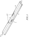
FIG. 1 is a perspective view of a cursor control device in accordance with the present invention. -
FIG. 2 is an exploded view of a part of the cursor control device in accordance with the present invention. -
FIG. 3 is an exploded view of the cursor control device in accordance with the present invention. -
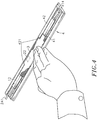
FIG. 4 is a schematic drawing showing a status of use of the cursor control device in accordance with the present invention. -
FIG. 5 is a sectional side view of the cursor control device in accordance with the present invention, showing movement of the sleeve in X-axis direction relative to the circuit module holder. -
FIG. 6 is a sectional side view of the cursor control device in accordance with the present invention, showing axial movement of the sleeve in Y-axis direction relative to the circuit module holder. -
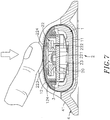
FIG. 7 is a sectional side view of the cursor control device in accordance with the present invention, showing the sleeve pressed downwards relative to the circuit module holder. -
FIG. 8 is a schematic sectional view of an alternate form of the cursor control device in accordance with the present invention. - Referring to
FIGS. 1 ,2 and3 , a cursor control device in accordance with the present invention is shown comprising acircuit module holder 1, acircuit module 2, asleeve 3 and ahousing 4. - The
circuit module holder 1 comprises afirst holder shell 11 and asecond holder shell 12. Thefirst holder shell 11 and thesecond holder shell 12 define there between an accommodation space 10. Thefirst holder shell 11 has a plurality oflimiters 111 symmetrically disposed, for example, near two distal ends thereof at two opposite lateral sides relative to the accommodation space 10 and a plurality of locatingmembers 112 symmetrically located on the two distal ends. Thesecond holder shell 12 has anopening 121 cut through the top and bottom walls thereof in communication with the accommodation space 10, a plurality of mountingportions 122 protruded from the bottom wall and a plurality ofstop members 123 corresponding to thelimiters 111 of thefirst holder shell 11. Further,elastic members 124 are respectively fastened to the bottom wall of thesecond holder shell 12 and stopped against thefirst holder shell 11 to support thesecond holder shell 12 above thefirst holder shell 11. - The
circuit module 2 is accommodated in the accommodation space 10 in thecircuit module holder 1, comprising acircuit board 20 carrying amicroprocessor 21, asensor module 22, acontrol switch 23 and atransmission interface 24. Thecircuit board 20 has a plurality of mountingportions 25 respectively fixedly fastened to themounting portions 122 of thesecond holder shell 12 of thecircuit module holder 1. Thesensor module 22, thecontrol switch 23 and thetransmission interface 24 are respectively electrically connected to themicroprocessor 21. Thesensor module 22 is disposed corresponding to theopening 121 of thesecond holder shell 12 of thecircuit module holder 1 for detecting the direction and amount of movement of thesleeve 3 relative to thecircuit module holder 1. Thetransmission interface 24 is adapted for communication with communication interface means of an external computer (not shown). Further, thesensor module 22 comprises asubstrate 222, alight source 223 mounted in thesubstrate 222, alens 224 molded on thesubstrate 222 over thelight source 223 and inserted into theopening 121 of thesecond holder shell 12 of thecircuit module holder 1 in flush with the top wall of the second holder shell 12 (seeFIG. 6 ) and asensor 221 installed in thesubstrate 222 for sensing reflected light from thesleeve 3 upon radiation of the light emitted by thelight source 223 through thelens 224. - The
sleeve 3 defines anaxial hole 31. By means of theaxial hole 31, thesleeve 3 is mounted around thecircuit module holder 1 and can be moved axially back and forth relative to thecircuit module holder 1 and rotated around thecircuit module holder 1. - The
housing 4 comprises abottom shell 41 and at least one, for example, twotop cover shells 42. The twotop cover shells 42 are covered on the top side of thebottom shell 41 such that anaccommodation chamber 40 is defined in between thebottom shell 41 and thetop cover shells 42 for accommodating the assembly of thesleeve 3, thecircuit module holder 1 and thecircuit module 2. Thebottom shell 41 has a plurality of male hook members (or female hook members) 411 symmetrically disposed at two opposite lateral sides, a plurality of locatingmembers 412 symmetrically disposed near two distal ends thereof and respectively fastened to the locatingmembers 112 of thefirst holder shell 11 by fasteningmembers 413, two protrudingblocks 414 respectively located on the two distal ends. Further, anopen space 421 is defined between the twotop cover shells 42 corresponding to theopening 121 of thesecond holder shell 12 of thecircuit module holder 1. Further, the twotop cover shells 42 have a substantially -shaped cross section. Further, eachtop cover shell 42 has a plurality of female hook members (or male hook members) 422 respectively fastened to the male hook members (or female hook members) 411 of thebottom shell 41 and a locatinggroove 423 coupled to one of the two protrudingblocks 414 of thebottom shell 41. - According to the present preferred embodiment, the
circuit module holder 1 is formed of thefirst holder shell 11 and thesecond holder shell 12. Alternatively, thecircuit module holder 1 can be a single-piece hollow bar having a circular or oval cross section allowing rotation and reciprocating displacement of thesleeve 3 therein. Further, thecircuit module holder 1 can be made from polyoxymetylene (POM), polytetrafluoroethylene (PTFE), ultra high molecular weight polyethylene (UHMWPE) or any of a variety of other suitable self-lubricating materials. Further, thesensor module 22 of thecircuit module 2 detects the direction and amount of movement of thesleeve 3 in such a manner that thelight source 223 emits light through thelens 224 onto thesleeve 3. When the light emitted by thelight source 223 falls upon a part of thesleeve 3, the surface characteristic (such as color, raised portions, recessed portions, smoothness) of the radiated part of thesleeve 3 interferes with light, causing a reflected light having a different characteristic to be produced. Thesensor 221 senses the reflected light from thesleeve 3 and provides a corresponding signal to themicroprocessor 21 for enabling themicroprocessor 21 to calculate the direction (in X-axis and Y-axis) and amount of movement of thesleeve 3 relative to thecircuit module holder 1 and to produce an output signal indicative of the direction and amount of movement of thesleeve 3 relative to thecircuit module holder 1 for transmission through atransmission line 241 of thetransmission interface 24 that extends through ahole 4141 on one protrudingblock 414 of thebottom shell 41 to the communication interface means of the external computer to control movement of a cursor on a display screen (not shown) that is electrically connected to the external computer. The technique how thesensor module 22 of thecircuit module 2 emits light and detest reflected light for enabling themicroprocessor 21 to calculate the direction and amount of movement of thesleeve 3 is of the known art and not within the scope of the claims of the present invention, and therefore no further detailed description in this regard is necessary. Further, thetransmission interface 24 can be a USB, PS2 or any of a variety of other wired communication interfaces. Alternatively, thetransmission interface 24 can be infrared, Bluetooth, radio frequency, or any other wireless communication interface. Further, thesleeve 3 can be made from mesh fabric, nonwoven fabric, plastics, rubber or leather, having transversely and longitudinally aligned recessed portions, raised portions or dots and coated with a layer of silver powder or silver paint for enabling thesensor motor 22 to sense the direction and amount of movement of thesleeve 3 relative to thecircuit module holder 1 accurately. - During assembly of the cursor control device, the
circuit module 2 is accommodated in the accommodation space 10 in thecircuit module holder 1, and then the mountingportions 25 of thecircuit board 20 are respectively fixedly fastened to the mountingportions 122 of thesecond holder shell 12 of thecircuit module holder 1 to have thelight source 223 be inserted into theopening 121 of thesecond holder shell 12 of thecircuit module holder 1 and kept in flush with the top wall of thesecond holder shell 12. At this time, thestop members 123 of thesecond holder shell 12 are respectively aimed at thelimiters 111 of thefirst holder shell 11, and theelastic members 124 of thesecond holder shell 12 are supported on thefirst holder shell 11. Thereafter, thesleeve 3 is sleeved onto thecircuit module holder 1 over theopening 121 to have thecircuit module holder 1 be received in theaxial hole 31 of thesleeve 3. Thereafter, thesleeve 3 with thecircuit module holder 1 are put in theaccommodation chamber 40 inside thehousing 4, and then the locatingmembers 412 of thebottom shell 41 are respectively fastened to the locatingmembers 112 of thefirst holder shell 11 byrespective fastening members 413 to have the female hook members (or male hook members) 422 and locatinggroove 423 of thetop cover shell 42 be respectively fastened to the male hook members (or female hook members) 411 and protrudingblocks 414 of thebottom shell 41. Thus, the cursor control device is well assembled. - Referring to
FIGS. 4~7 , the cursor control device can be used in a personal computer, notebook computer, mobile telephone or any of a variety of personal electronic devices. In case of a wired design, thetransmission line 241 of thetransmission interface 24 of the cursor control device is connected to the communication interface means of the personal electronic device, for example, personal computer. When the user rests the wrist of the hand on a pad that is disposed adjacent to the cursor control device, the user can move thesleeve 3 in X-axis direction or Y-axis direction relative to thecircuit module holder 1 and thehousing 4 with the fingers. At this time, themicroprocessor 21 outputs an output signal indicative of the direction and amount of movement of thesleeve 3 relative to thecircuit module holder 1 through thetransmission line 241 of thetransmission interface 24 to the communication interface means of the computer to control movement of the cursor on the display screen. Because thecircuit module holder 1 is made from a self-lubricating material, it facilitates movement of thesleeve 3, and therefore thesleeve 3 can be moved smoothly in theaccommodation chamber 40 inside thehousing 4 without causing much friction resistance between thesleeve 3 and thecircuit module holder 1. - Further, when the user applies a downward pressure to the
sleeve 3, thestop members 123 of thesecond holder shell 12 are lowered toward thelimiters 111 of thefirst holder shell 11 and theelastic members 124 of thesecond holder shell 12 are compressed by thefirst holder shell 11, and at the same time thecontrol switch 23 that is located on the bottom wall of thecircuit board 20 is triggered by thefirst holder shell 11 to produce a triggering signal for controlling the cursor to grab a web page and to scroll up or down the web page or to click a menu selection. When the user stops from moving thesleeve 3, theelastic members 124 immediately lift thesecond holder shell 12 from thefirst holder shell 11, returning thesecond holder shell 12 to its former position. - Further, because the
circuit module 2 is accommodated in the accommodation space 10 in thecircuit module holder 1 and affixed to thesecond holder shell 12, thecircuit module 2 is protected inside thehousing 4 and does not requires an extra installation space in the personal electronic device. Therefore, the cursor control device has an integrated outer appearance and a small-size characteristic. - As stated above, the invention provides a cursor control device applicable for use in a personal computer, notebook computer, mobile telephone or any of a variety of electronic devices for moving a cursor displayed on a display screen or controlling the cursor to grab a web page and to scroll up or down the web page or to click a menu selection. The
circuit module holder 1 of the cursor control device accommodates thecircuit module 2 on the inside and is received in thesleeve 3 inside thehousing 4. Further, two support members 5 may be used to substitute for theaforesaid housing 4 and affixed to the bottom wall of thefirst holder shell 11 for supporting thecircuit module holder 1 on a flat wall, allowing movement of thesleeve 3 relative to thecircuit module holder 1 and thecircuit module 2 in X-axis and Y-axis directions. This mounting arrangement facilitates cleaning and replacement of thesleeve 3, enhancing the functioning of the cursor control device. - A prototype of cursor control device has been constructed with the features of
FIGS. 1-8 . The control device functions smoothly to provide all of the features disclosed earlier. -
Applicant: EKTOUCH CO., LTD Patent Title : CURSOR CONTROL DEVICE 1- circuit module holder 121- opening 10- accommodation space 122- mounting portion 11- first holder shell 123-stop member 111-limiter 124-elastic member 112-locating member 12- second holder shell 2- circuit module 224- lens 20- circuit board 23- control switch 24-transmission interface 21- microprocessor 241- transmission line 22- sensor module 25- mounting portion 221-sensor 222- substrate 223-light source 3- sleeve 4- housing 40- accommodation chamber 31- axial hole 41- bottom shell 41- bottom shell 411-male hook member (or female hook members) 412- locating member 413-fastening member 414- protruding block 4141- hole 5- support member 42-top cover shell 421- open space 422- female hook members (or male hook members) 423- locating groove
Claims (17)
- A cursor control device adapted for controlling a cursor on a display screen of an electronic device, comprising:a circuit module holder (1), said circuit module holder (1) having an accommodation space (10) defined therein and an opening (121) on a top side thereof for exposing said accommodation space (10);a sleeve (3) mounted around said circuit module holder (1) and movable leftwards and rightwards relative to said circuit module holder (1) and rotatable forwards and backwards around said circuit module holder (1); anda circuit module (2) accommodated in said accommodation space (10) of said circuit module holder (1), said circuit module (2) comprising a circuit board (20), a sensor module (22) installed in said circuit board (20) and disposed corresponding to the opening (121) of the circuit module holder (1) for sensing the direction and amount of movement of said sleeve (3) relative to said circuit module holder (1) through said opening and producing a signal indicative of the direction and amount of movement of said sleeve (3) relative to said circuit module holder (1), a microprocessor (21) installed in said circuit board (20) and electrically connected with said sensor module (22) for receiving the signal produced by said sensor module (22) and producing a control signal for controlling said cursor on said display screen subject to the signal received from said sensor module (22),characterized in that said circuit module (2) further comprises a control switch (23) electrically connected with said microprocessor (21), wherein said control switch (23) is disposed inside said circuit module holder (1), installed in said circuit board (20), and movable downwards to urge against an inner wall of said circuit module holder (1) when said sleeve (3) is pressed by a user so as to produce a triggering signal.
- The cursor control device as claimed in claim 1, characterized in that said circuit module holder (1) comprises:a first holder shell (11), said first holder shell (11) having a plurality of limiters (111);a second holder shell (12) disposed above said first holder shell (11), said second holder shell (12) having a plurality of stop members (123) downwardly extended from a bottom wall thereof and respectively aimed at said limiters (111) of said first holder shell (11); anda plurality of elastic members (124) disposed between said first holder shell (11) and said second holder shell (12) for supporting said second holder shell (12) above said first holder shell (11),wherein said control switch (23) is disposed on a bottom surface of said circuit board (20), and when said sleeve (3) is pressed by the user, said second holder shell (12) moves toward said first holder shell (11) while carrying said control switch (23) to move downwards to urge against said first holder shell (11), thereby producing the triggering signal.
- The cursor control device as claimed in claim 1, characterized in that said circuit module holder (1) has a plurality of mounting portions (122) suspending on the inside; said circuit board (20) of said circuit module (2) has a plurality of mounting portions (122) respectively fixedly fastened to the mounting portions (122) of said circuit module holder (1).
- The cursor control device as claimed in claim 1, characterized in that said circuit module (2) further comprises a transmission interface (24) electrically connected with said microprocessor (21) and adapted for transmitting said control signal to said electronic device to control said cursor on said display screen.
- The cursor control device as claimed in claim 4, characterized in that said transmission interface (24) is a wired transmission interface (24) selected from a group of universal serial bus interface and PS2 keyboard/mouse interface.
- The cursor control device as claimed in claim 4, characterized in that said transmission interface (24) is a wireless transmission interface (24) selected from a group of infrared, Bluetooth and radio frequency transmission techniques.
- The cursor control device as claimed in claim 1, characterized in that said sensor module (22) of said circuit module (2) comprises a substrate (222), a light source (223) mounted in said substrate (222) adapted to emit light onto said sleeve (3), and a sensor (221) adapted to detect reflected light from said sleeve (3).
- The cursor control device as claimed in claim 1, characterized in that said sleeve (3) defines an axial hole (31) that receives said circuit module holder (1).
- The cursor control device as claimed in claim 1, characterized in further comprising a housing (4), said housing comprising a bottom shell (41), at least one top cover shell (42) covering said bottom shell (41), an accommodation chamber (40) defined in between said bottom shell (41) and said at least one top cover shell (42) for accommodating said circuit module holder (1) and said sleeve (3) for enabling said sleeve (3) to be moved relative to said circuit module holder (1), said at least one top cover shell (42) each having a plurality of locating members (112) symmetrically disposed near two distal ends thereof respectively fastened to respective locating members (112) at said circuit module holder (1) by fastening members (413).
- The cursor control device as claimed in claim 9, characterized in that said bottom shell (41) has a plurality of first hook members symmetrically disposed at two opposite lateral sides, each said at least one top cover shell (42) has a plurality of second hook members respectively fastened to the male hook members (411) of said bottom shell (41).
- The cursor control device as claimed in claim 9, characterized in that said bottom shell (41) of said housing (4) has two protruding blocks (414) respectively located on two distal ends thereof; said at least one top cover shell (42) of said housing (4) has two locating grooves (423) respectively coupled to the two protruding blocks (414) of said bottom shell (41).
- The cursor control device as claimed in claim 1, characterized in that said circuit module holder (1) has two support members (5) fixedly fastened to a bottom wall thereof for positioning on a flat wall.
- The cursor control device as claimed in claim 9, characterized in that said circuit module holder (1) is formed of a first holder shell (11) and a second holder shell (12) and shaped like a hollow bar.
- The cursor control device as claimed in claim 9, characterized in that said circuit module holder (1) is prepared from a self-lubricating material selected from the group consisting of polyoxymetylene (POM), polytetrafluoroethylene (PTFE) and ultra high molecular weight polyethylene (UHMWPE).
- The cursor control device as claimed in claim 9, characterized in that said sleeve (3) is prepared from one of the materials of mesh fabric and nonwoven fabric.
- The cursor control device as claimed in claim 9, characterized in that said sleeve (3) is prepared from one of the materials of plastics and rubber.
- The cursor control device as claimed in claim 9, characterized in that said sleeve (3) is prepared from leather.
Applications Claiming Priority (1)
| Application Number | Priority Date | Filing Date | Title |
|---|---|---|---|
| TW098207649U TWM364911U (en) | 2009-05-05 | 2009-05-05 | Operation and control apparatus |
Publications (3)
| Publication Number | Publication Date |
|---|---|
| EP2249232A2 EP2249232A2 (en) | 2010-11-10 |
| EP2249232A3 EP2249232A3 (en) | 2015-06-10 |
| EP2249232B1 true EP2249232B1 (en) | 2017-04-05 |
Family
ID=42357883
Family Applications (1)
| Application Number | Title | Priority Date | Filing Date |
|---|---|---|---|
| EP10001120.4A Active EP2249232B1 (en) | 2009-05-05 | 2010-02-03 | Cursor control device |
Country Status (5)
| Country | Link |
|---|---|
| US (1) | US20110037693A1 (en) |
| EP (1) | EP2249232B1 (en) |
| JP (1) | JP3160357U (en) |
| DK (1) | DK2249232T3 (en) |
| TW (1) | TWM364911U (en) |
Families Citing this family (8)
| Publication number | Priority date | Publication date | Assignee | Title |
|---|---|---|---|---|
| US8823644B2 (en) | 2009-12-08 | 2014-09-02 | Contour Design Inc. | Inner-sensor based pointing device |
| US9024873B2 (en) * | 2010-05-04 | 2015-05-05 | Chen-Min Hung | Control device |
| TWM422108U (en) * | 2011-08-01 | 2012-02-01 | Ergzon Co Ltd | Control device |
| SE536635C2 (en) * | 2012-11-02 | 2014-04-15 | Gunnar Drougge | Coordinate device with roller cylinder |
| WO2014122191A1 (en) | 2013-02-05 | 2014-08-14 | Contour Design, Inc. | Improved pointing device |
| CN107077232B (en) | 2015-05-08 | 2020-11-13 | 康杜尔设计公司 | Pointing device holder assembly and system |
| US11023053B2 (en) | 2016-11-11 | 2021-06-01 | Contour Innovations Llc | Inner-sensor pointing device system |
| WO2018147824A1 (en) | 2017-02-07 | 2018-08-16 | Hewlett-Packard Development Company, L.P. | Stylus nibs |
Family Cites Families (28)
| Publication number | Priority date | Publication date | Assignee | Title |
|---|---|---|---|---|
| US5270690A (en) * | 1989-05-08 | 1993-12-14 | Harold C. Avila | Bidimensional input control system |
| EP0477098B1 (en) * | 1990-09-18 | 1996-06-26 | Fujitsu Limited | Cursor displacement control device for a computer display |
| US6906700B1 (en) * | 1992-03-05 | 2005-06-14 | Anascape | 3D controller with vibration |
| JP3268467B2 (en) * | 1992-09-08 | 2002-03-25 | 株式会社日立製作所 | Telephone |
| DE69720854T2 (en) * | 1996-05-29 | 2003-11-20 | Fujitsu Takamisawa Component | Guide device for moving and positioning a pointer on a computer screen |
| JPH10207616A (en) * | 1997-01-20 | 1998-08-07 | Sharp Corp | Inputting device |
| US6731267B1 (en) * | 1997-09-15 | 2004-05-04 | Veijo Matias Tuoriniemi | Single touch dual axis input device |
| US20080055241A1 (en) * | 1998-03-26 | 2008-03-06 | Immersion Corporation | Systems and Methods for Haptic Feedback Effects for Control Knobs |
| JP2000132331A (en) * | 1998-08-21 | 2000-05-12 | Shinsuke Hamaji | Roller slide type pointing device |
| KR100330160B1 (en) * | 1998-10-13 | 2002-05-09 | 윤종용 | Portable computer with pointing device |
| US6633277B1 (en) * | 2000-05-30 | 2003-10-14 | 3Com Corporation | Compact 3-state data entry device |
| US7164412B2 (en) * | 2001-03-30 | 2007-01-16 | Ado Max Technology Co., Ltd. | Key free mouse |
| US7084856B2 (en) * | 2001-10-22 | 2006-08-01 | Apple Computer, Inc. | Mouse having a rotary dial |
| US6724367B2 (en) * | 2001-11-20 | 2004-04-20 | General Motors Corporation | Manually-controlled device for moving a cursor |
| AUPS049502A0 (en) * | 2002-02-13 | 2002-03-07 | Silverbrook Research Pty. Ltd. | Methods and system (ap58) |
| US7358963B2 (en) * | 2002-09-09 | 2008-04-15 | Apple Inc. | Mouse having an optically-based scrolling feature |
| JP4391193B2 (en) * | 2003-03-27 | 2009-12-24 | 本田技研工業株式会社 | Operating device |
| JP2005242983A (en) * | 2004-01-30 | 2005-09-08 | Ntt Docomo Inc | Input key and input device |
| JP2005321996A (en) * | 2004-05-07 | 2005-11-17 | Pioneer Electronic Corp | Information input device and method |
| TWM262824U (en) * | 2004-09-17 | 2005-04-21 | Paten Wireless Technology Inc | Multi-directional pointing device |
| WO2006052079A2 (en) * | 2004-11-10 | 2006-05-18 | Lg Electronics Inc. | Remote monitor in electric home appliances |
| US8188974B2 (en) * | 2005-09-29 | 2012-05-29 | Logitech Europe S.A. | Input device with reduced friction |
| TW200809588A (en) * | 2006-08-09 | 2008-02-16 | Kye Systems Corp | Pressable touch module and touch input device |
| US20080174571A1 (en) * | 2007-01-23 | 2008-07-24 | Had-Wen Chen | Pen-Type Input Device with Remote Control |
| US20080278444A1 (en) * | 2007-05-11 | 2008-11-13 | Schelling Anna C | User input system |
| US20080278443A1 (en) * | 2007-05-11 | 2008-11-13 | Schelling Anna C | User input device |
| TW200912708A (en) * | 2007-09-14 | 2009-03-16 | Kye Systems Corp | Computer input device |
| US8294670B2 (en) * | 2008-02-05 | 2012-10-23 | Research In Motion Limited | Optically based input mechanism for a handheld electronic communication device |
-
2009
- 2009-05-05 TW TW098207649U patent/TWM364911U/en unknown
-
2010
- 2010-02-03 EP EP10001120.4A patent/EP2249232B1/en active Active
- 2010-02-03 DK DK10001120.4T patent/DK2249232T3/en active
- 2010-03-01 JP JP2010001254U patent/JP3160357U/en not_active Expired - Fee Related
- 2010-05-04 US US12/662,788 patent/US20110037693A1/en not_active Abandoned
Non-Patent Citations (1)
| Title |
|---|
| None * |
Also Published As
| Publication number | Publication date |
|---|---|
| EP2249232A3 (en) | 2015-06-10 |
| DK2249232T3 (en) | 2017-07-17 |
| US20110037693A1 (en) | 2011-02-17 |
| EP2249232A2 (en) | 2010-11-10 |
| JP3160357U (en) | 2010-06-24 |
| TWM364911U (en) | 2009-09-11 |
Similar Documents
| Publication | Publication Date | Title |
|---|---|---|
| EP2249232B1 (en) | Cursor control device | |
| US9024873B2 (en) | Control device | |
| US7692667B2 (en) | Handheld computer having moveable segments that are interactive with an integrated display | |
| US20020140676A1 (en) | Key free mouse | |
| US8830166B2 (en) | Sleeve and control device with such sleeve | |
| US20110018798A1 (en) | Cursor control device | |
| US6724365B1 (en) | Scroll wheel device for portable computers | |
| US9772698B2 (en) | Inner-sensor based pointing device | |
| US20110285671A1 (en) | Stylus and electronic device | |
| US20070139377A1 (en) | Cursor control device | |
| US7379051B2 (en) | Foldable computer mouse | |
| US8314771B2 (en) | Operation control device | |
| EP2360549A2 (en) | Control device | |
| US7133021B2 (en) | Finger-fitting pointing device | |
| US8203532B2 (en) | Portable mouse attachable on a surface of an object | |
| US11137836B2 (en) | Electronic device | |
| KR200439202Y1 (en) | A noiseless mouse for computer | |
| US10782797B2 (en) | Mouse device | |
| US20050110779A1 (en) | Pen-like mouse device | |
| CN218383891U (en) | Input device and electronic apparatus | |
| JP3167785U (en) | Operation control device | |
| WO2013091332A1 (en) | Operation and control device | |
| KR20090039285A (en) | Movable type mouse pad | |
| JP2005522749A (en) | Electronic pen input device | |
| CA2705981A1 (en) | Control device |
Legal Events
| Date | Code | Title | Description |
|---|---|---|---|
| PUAI | Public reference made under article 153(3) epc to a published international application that has entered the european phase |
Free format text: ORIGINAL CODE: 0009012 |
|
| AK | Designated contracting states |
Kind code of ref document: A2 Designated state(s): AT BE BG CH CY CZ DE DK EE ES FI FR GB GR HR HU IE IS IT LI LT LU LV MC MK MT NL NO PL PT RO SE SI SK SM TR |
|
| AX | Request for extension of the european patent |
Extension state: AL BA RS |
|
| RAP1 | Party data changed (applicant data changed or rights of an application transferred) |
Owner name: LIANG, HSU |
|
| REG | Reference to a national code |
Ref country code: SE Ref legal event code: TRCL |
|
| REG | Reference to a national code |
Ref country code: SE Ref legal event code: TRCL |
|
| RAP1 | Party data changed (applicant data changed or rights of an application transferred) |
Owner name: HUNG, CHEN-MIN |
|
| PUAL | Search report despatched |
Free format text: ORIGINAL CODE: 0009013 |
|
| AK | Designated contracting states |
Kind code of ref document: A3 Designated state(s): AT BE BG CH CY CZ DE DK EE ES FI FR GB GR HR HU IE IS IT LI LT LU LV MC MK MT NL NO PL PT RO SE SI SK SM TR |
|
| AX | Request for extension of the european patent |
Extension state: AL BA RS |
|
| RIC1 | Information provided on ipc code assigned before grant |
Ipc: G06F 3/033 20130101AFI20150504BHEP Ipc: G06F 3/03 20060101ALI20150504BHEP |
|
| 17P | Request for examination filed |
Effective date: 20151210 |
|
| RBV | Designated contracting states (corrected) |
Designated state(s): AT BE BG CH CY CZ DE DK EE ES FI FR GB GR HR HU IE IS IT LI LT LU LV MC MK MT NL NO PL PT RO SE SI SK SM TR |
|
| 17Q | First examination report despatched |
Effective date: 20160229 |
|
| REG | Reference to a national code |
Ref country code: DE Ref legal event code: R079 Ref document number: 602010041225 Country of ref document: DE Free format text: PREVIOUS MAIN CLASS: G06F0003033000 Ipc: G06F0003033800 |
|
| RIC1 | Information provided on ipc code assigned before grant |
Ipc: G06F 3/0354 20130101ALI20160823BHEP Ipc: G06F 3/0338 20130101AFI20160823BHEP Ipc: G06F 3/042 20060101ALI20160823BHEP |
|
| GRAP | Despatch of communication of intention to grant a patent |
Free format text: ORIGINAL CODE: EPIDOSNIGR1 |
|
| INTG | Intention to grant announced |
Effective date: 20160929 |
|
| INTG | Intention to grant announced |
Effective date: 20161006 |
|
| RAP1 | Party data changed (applicant data changed or rights of an application transferred) |
Owner name: CONTOUR DESIGN, INC. |
|
| GRAS | Grant fee paid |
Free format text: ORIGINAL CODE: EPIDOSNIGR3 |
|
| GRAA | (expected) grant |
Free format text: ORIGINAL CODE: 0009210 |
|
| AK | Designated contracting states |
Kind code of ref document: B1 Designated state(s): AT BE BG CH CY CZ DE DK EE ES FI FR GB GR HR HU IE IS IT LI LT LU LV MC MK MT NL NO PL PT RO SE SI SK SM TR |
|
| REG | Reference to a national code |
Ref country code: GB Ref legal event code: FG4D |
|
| REG | Reference to a national code |
Ref country code: CH Ref legal event code: EP |
|
| REG | Reference to a national code |
Ref country code: AT Ref legal event code: REF Ref document number: 882385 Country of ref document: AT Kind code of ref document: T Effective date: 20170415 |
|
| REG | Reference to a national code |
Ref country code: IE Ref legal event code: FG4D |
|
| REG | Reference to a national code |
Ref country code: DE Ref legal event code: R096 Ref document number: 602010041225 Country of ref document: DE |
|
| REG | Reference to a national code |
Ref country code: DK Ref legal event code: T3 Effective date: 20170706 |
|
| REG | Reference to a national code |
Ref country code: SE Ref legal event code: TRGR |
|
| REG | Reference to a national code |
Ref country code: NL Ref legal event code: MP Effective date: 20170405 |
|
| REG | Reference to a national code |
Ref country code: LT Ref legal event code: MG4D |
|
| REG | Reference to a national code |
Ref country code: AT Ref legal event code: MK05 Ref document number: 882385 Country of ref document: AT Kind code of ref document: T Effective date: 20170405 |
|
| PG25 | Lapsed in a contracting state [announced via postgrant information from national office to epo] |
Ref country code: NL Free format text: LAPSE BECAUSE OF FAILURE TO SUBMIT A TRANSLATION OF THE DESCRIPTION OR TO PAY THE FEE WITHIN THE PRESCRIBED TIME-LIMIT Effective date: 20170405 |
|
| PG25 | Lapsed in a contracting state [announced via postgrant information from national office to epo] |
Ref country code: NO Free format text: LAPSE BECAUSE OF FAILURE TO SUBMIT A TRANSLATION OF THE DESCRIPTION OR TO PAY THE FEE WITHIN THE PRESCRIBED TIME-LIMIT Effective date: 20170705 Ref country code: HR Free format text: LAPSE BECAUSE OF FAILURE TO SUBMIT A TRANSLATION OF THE DESCRIPTION OR TO PAY THE FEE WITHIN THE PRESCRIBED TIME-LIMIT Effective date: 20170405 Ref country code: FI Free format text: LAPSE BECAUSE OF FAILURE TO SUBMIT A TRANSLATION OF THE DESCRIPTION OR TO PAY THE FEE WITHIN THE PRESCRIBED TIME-LIMIT Effective date: 20170405 Ref country code: ES Free format text: LAPSE BECAUSE OF FAILURE TO SUBMIT A TRANSLATION OF THE DESCRIPTION OR TO PAY THE FEE WITHIN THE PRESCRIBED TIME-LIMIT Effective date: 20170405 Ref country code: LT Free format text: LAPSE BECAUSE OF FAILURE TO SUBMIT A TRANSLATION OF THE DESCRIPTION OR TO PAY THE FEE WITHIN THE PRESCRIBED TIME-LIMIT Effective date: 20170405 Ref country code: AT Free format text: LAPSE BECAUSE OF FAILURE TO SUBMIT A TRANSLATION OF THE DESCRIPTION OR TO PAY THE FEE WITHIN THE PRESCRIBED TIME-LIMIT Effective date: 20170405 Ref country code: GR Free format text: LAPSE BECAUSE OF FAILURE TO SUBMIT A TRANSLATION OF THE DESCRIPTION OR TO PAY THE FEE WITHIN THE PRESCRIBED TIME-LIMIT Effective date: 20170706 |
|
| PG25 | Lapsed in a contracting state [announced via postgrant information from national office to epo] |
Ref country code: IS Free format text: LAPSE BECAUSE OF FAILURE TO SUBMIT A TRANSLATION OF THE DESCRIPTION OR TO PAY THE FEE WITHIN THE PRESCRIBED TIME-LIMIT Effective date: 20170805 Ref country code: BG Free format text: LAPSE BECAUSE OF FAILURE TO SUBMIT A TRANSLATION OF THE DESCRIPTION OR TO PAY THE FEE WITHIN THE PRESCRIBED TIME-LIMIT Effective date: 20170705 Ref country code: PL Free format text: LAPSE BECAUSE OF FAILURE TO SUBMIT A TRANSLATION OF THE DESCRIPTION OR TO PAY THE FEE WITHIN THE PRESCRIBED TIME-LIMIT Effective date: 20170405 Ref country code: LV Free format text: LAPSE BECAUSE OF FAILURE TO SUBMIT A TRANSLATION OF THE DESCRIPTION OR TO PAY THE FEE WITHIN THE PRESCRIBED TIME-LIMIT Effective date: 20170405 |
|
| REG | Reference to a national code |
Ref country code: DE Ref legal event code: R097 Ref document number: 602010041225 Country of ref document: DE |
|
| PG25 | Lapsed in a contracting state [announced via postgrant information from national office to epo] |
Ref country code: CZ Free format text: LAPSE BECAUSE OF FAILURE TO SUBMIT A TRANSLATION OF THE DESCRIPTION OR TO PAY THE FEE WITHIN THE PRESCRIBED TIME-LIMIT Effective date: 20170405 Ref country code: RO Free format text: LAPSE BECAUSE OF FAILURE TO SUBMIT A TRANSLATION OF THE DESCRIPTION OR TO PAY THE FEE WITHIN THE PRESCRIBED TIME-LIMIT Effective date: 20170405 Ref country code: EE Free format text: LAPSE BECAUSE OF FAILURE TO SUBMIT A TRANSLATION OF THE DESCRIPTION OR TO PAY THE FEE WITHIN THE PRESCRIBED TIME-LIMIT Effective date: 20170405 Ref country code: SK Free format text: LAPSE BECAUSE OF FAILURE TO SUBMIT A TRANSLATION OF THE DESCRIPTION OR TO PAY THE FEE WITHIN THE PRESCRIBED TIME-LIMIT Effective date: 20170405 |
|
| PLBE | No opposition filed within time limit |
Free format text: ORIGINAL CODE: 0009261 |
|
| STAA | Information on the status of an ep patent application or granted ep patent |
Free format text: STATUS: NO OPPOSITION FILED WITHIN TIME LIMIT |
|
| PG25 | Lapsed in a contracting state [announced via postgrant information from national office to epo] |
Ref country code: SM Free format text: LAPSE BECAUSE OF FAILURE TO SUBMIT A TRANSLATION OF THE DESCRIPTION OR TO PAY THE FEE WITHIN THE PRESCRIBED TIME-LIMIT Effective date: 20170405 Ref country code: IT Free format text: LAPSE BECAUSE OF FAILURE TO SUBMIT A TRANSLATION OF THE DESCRIPTION OR TO PAY THE FEE WITHIN THE PRESCRIBED TIME-LIMIT Effective date: 20170405 |
|
| 26N | No opposition filed |
Effective date: 20180108 |
|
| PG25 | Lapsed in a contracting state [announced via postgrant information from national office to epo] |
Ref country code: SI Free format text: LAPSE BECAUSE OF FAILURE TO SUBMIT A TRANSLATION OF THE DESCRIPTION OR TO PAY THE FEE WITHIN THE PRESCRIBED TIME-LIMIT Effective date: 20170405 |
|
| REG | Reference to a national code |
Ref country code: DE Ref legal event code: R119 Ref document number: 602010041225 Country of ref document: DE |
|
| REG | Reference to a national code |
Ref country code: CH Ref legal event code: PL |
|
| PG25 | Lapsed in a contracting state [announced via postgrant information from national office to epo] |
Ref country code: MC Free format text: LAPSE BECAUSE OF FAILURE TO SUBMIT A TRANSLATION OF THE DESCRIPTION OR TO PAY THE FEE WITHIN THE PRESCRIBED TIME-LIMIT Effective date: 20170405 |
|
| GBPC | Gb: european patent ceased through non-payment of renewal fee |
Effective date: 20180203 |
|
| REG | Reference to a national code |
Ref country code: IE Ref legal event code: MM4A |
|
| REG | Reference to a national code |
Ref country code: BE Ref legal event code: MM Effective date: 20180228 |
|
| PG25 | Lapsed in a contracting state [announced via postgrant information from national office to epo] |
Ref country code: LU Free format text: LAPSE BECAUSE OF NON-PAYMENT OF DUE FEES Effective date: 20180203 Ref country code: LI Free format text: LAPSE BECAUSE OF NON-PAYMENT OF DUE FEES Effective date: 20180228 Ref country code: CH Free format text: LAPSE BECAUSE OF NON-PAYMENT OF DUE FEES Effective date: 20180228 |
|
| REG | Reference to a national code |
Ref country code: FR Ref legal event code: ST Effective date: 20181031 |
|
| PG25 | Lapsed in a contracting state [announced via postgrant information from national office to epo] |
Ref country code: DE Free format text: LAPSE BECAUSE OF NON-PAYMENT OF DUE FEES Effective date: 20180901 Ref country code: IE Free format text: LAPSE BECAUSE OF NON-PAYMENT OF DUE FEES Effective date: 20180203 |
|
| PG25 | Lapsed in a contracting state [announced via postgrant information from national office to epo] |
Ref country code: FR Free format text: LAPSE BECAUSE OF NON-PAYMENT OF DUE FEES Effective date: 20180228 Ref country code: BE Free format text: LAPSE BECAUSE OF NON-PAYMENT OF DUE FEES Effective date: 20180228 Ref country code: GB Free format text: LAPSE BECAUSE OF NON-PAYMENT OF DUE FEES Effective date: 20180203 |
|
| PG25 | Lapsed in a contracting state [announced via postgrant information from national office to epo] |
Ref country code: MT Free format text: LAPSE BECAUSE OF NON-PAYMENT OF DUE FEES Effective date: 20180203 |
|
| PG25 | Lapsed in a contracting state [announced via postgrant information from national office to epo] |
Ref country code: TR Free format text: LAPSE BECAUSE OF FAILURE TO SUBMIT A TRANSLATION OF THE DESCRIPTION OR TO PAY THE FEE WITHIN THE PRESCRIBED TIME-LIMIT Effective date: 20170405 |
|
| PG25 | Lapsed in a contracting state [announced via postgrant information from national office to epo] |
Ref country code: HU Free format text: LAPSE BECAUSE OF FAILURE TO SUBMIT A TRANSLATION OF THE DESCRIPTION OR TO PAY THE FEE WITHIN THE PRESCRIBED TIME-LIMIT; INVALID AB INITIO Effective date: 20100203 Ref country code: PT Free format text: LAPSE BECAUSE OF FAILURE TO SUBMIT A TRANSLATION OF THE DESCRIPTION OR TO PAY THE FEE WITHIN THE PRESCRIBED TIME-LIMIT Effective date: 20170405 |
|
| PG25 | Lapsed in a contracting state [announced via postgrant information from national office to epo] |
Ref country code: CY Free format text: LAPSE BECAUSE OF FAILURE TO SUBMIT A TRANSLATION OF THE DESCRIPTION OR TO PAY THE FEE WITHIN THE PRESCRIBED TIME-LIMIT Effective date: 20170405 Ref country code: MK Free format text: LAPSE BECAUSE OF NON-PAYMENT OF DUE FEES Effective date: 20170405 |
|
| PGFP | Annual fee paid to national office [announced via postgrant information from national office to epo] |
Ref country code: DK Payment date: 20230220 Year of fee payment: 14 |
|
| PGFP | Annual fee paid to national office [announced via postgrant information from national office to epo] |
Ref country code: SE Payment date: 20230216 Year of fee payment: 14 |
|
| P01 | Opt-out of the competence of the unified patent court (upc) registered |
Effective date: 20230515 |