EP2249175A1 - Color doppler mode image processing in an ultrasound system - Google Patents
Color doppler mode image processing in an ultrasound system Download PDFInfo
- Publication number
- EP2249175A1 EP2249175A1 EP10160682A EP10160682A EP2249175A1 EP 2249175 A1 EP2249175 A1 EP 2249175A1 EP 10160682 A EP10160682 A EP 10160682A EP 10160682 A EP10160682 A EP 10160682A EP 2249175 A1 EP2249175 A1 EP 2249175A1
- Authority
- EP
- European Patent Office
- Prior art keywords
- power
- images
- image
- mask
- velocity
- Prior art date
- Legal status (The legal status is an assumption and is not a legal conclusion. Google has not performed a legal analysis and makes no representation as to the accuracy of the status listed.)
- Granted
Links
- 238000002604 ultrasonography Methods 0.000 title claims abstract description 41
- 238000009499 grossing Methods 0.000 claims description 30
- 238000001914 filtration Methods 0.000 claims description 21
- 238000000034 method Methods 0.000 claims description 18
- 150000001875 compounds Chemical class 0.000 claims description 17
- 230000000873 masking effect Effects 0.000 claims description 14
- 238000013329 compounding Methods 0.000 claims 2
- 210000004204 blood vessel Anatomy 0.000 description 17
- 230000017531 blood circulation Effects 0.000 description 16
- 238000010586 diagram Methods 0.000 description 11
- 238000012986 modification Methods 0.000 description 3
- 230000004048 modification Effects 0.000 description 3
- 239000000523 sample Substances 0.000 description 3
- 230000015572 biosynthetic process Effects 0.000 description 2
- 206010009192 Circulatory collapse Diseases 0.000 description 1
- 230000005540 biological transmission Effects 0.000 description 1
- 230000000740 bleeding effect Effects 0.000 description 1
- 239000008280 blood Substances 0.000 description 1
- 210000004369 blood Anatomy 0.000 description 1
- 230000001934 delay Effects 0.000 description 1
- 230000001066 destructive effect Effects 0.000 description 1
- 238000003745 diagnosis Methods 0.000 description 1
- 230000006870 function Effects 0.000 description 1
- 238000002372 labelling Methods 0.000 description 1
- 230000000877 morphologic effect Effects 0.000 description 1
- 210000003205 muscle Anatomy 0.000 description 1
- 210000004165 myocardium Anatomy 0.000 description 1
- 230000004044 response Effects 0.000 description 1
- 238000012285 ultrasound imaging Methods 0.000 description 1
Images

Classifications
-
- G—PHYSICS
- G01—MEASURING; TESTING
- G01S—RADIO DIRECTION-FINDING; RADIO NAVIGATION; DETERMINING DISTANCE OR VELOCITY BY USE OF RADIO WAVES; LOCATING OR PRESENCE-DETECTING BY USE OF THE REFLECTION OR RERADIATION OF RADIO WAVES; ANALOGOUS ARRANGEMENTS USING OTHER WAVES
- G01S15/00—Systems using the reflection or reradiation of acoustic waves, e.g. sonar systems
- G01S15/88—Sonar systems specially adapted for specific applications
- G01S15/89—Sonar systems specially adapted for specific applications for mapping or imaging
- G01S15/8906—Short-range imaging systems; Acoustic microscope systems using pulse-echo techniques
- G01S15/8979—Combined Doppler and pulse-echo imaging systems
-
- A—HUMAN NECESSITIES
- A61—MEDICAL OR VETERINARY SCIENCE; HYGIENE
- A61B—DIAGNOSIS; SURGERY; IDENTIFICATION
- A61B8/00—Diagnosis using ultrasonic, sonic or infrasonic waves
- A61B8/13—Tomography
- A61B8/14—Echo-tomography
-
- G—PHYSICS
- G01—MEASURING; TESTING
- G01S—RADIO DIRECTION-FINDING; RADIO NAVIGATION; DETERMINING DISTANCE OR VELOCITY BY USE OF RADIO WAVES; LOCATING OR PRESENCE-DETECTING BY USE OF THE REFLECTION OR RERADIATION OF RADIO WAVES; ANALOGOUS ARRANGEMENTS USING OTHER WAVES
- G01S7/00—Details of systems according to groups G01S13/00, G01S15/00, G01S17/00
- G01S7/52—Details of systems according to groups G01S13/00, G01S15/00, G01S17/00 of systems according to group G01S15/00
- G01S7/52017—Details of systems according to groups G01S13/00, G01S15/00, G01S17/00 of systems according to group G01S15/00 particularly adapted to short-range imaging
- G01S7/52053—Display arrangements
- G01S7/52057—Cathode ray tube displays
- G01S7/5206—Two-dimensional coordinated display of distance and direction; B-scan display
-
- G—PHYSICS
- G06—COMPUTING; CALCULATING OR COUNTING
- G06T—IMAGE DATA PROCESSING OR GENERATION, IN GENERAL
- G06T7/00—Image analysis
- G06T7/10—Segmentation; Edge detection
- G06T7/11—Region-based segmentation
-
- G—PHYSICS
- G06—COMPUTING; CALCULATING OR COUNTING
- G06T—IMAGE DATA PROCESSING OR GENERATION, IN GENERAL
- G06T7/00—Image analysis
- G06T7/10—Segmentation; Edge detection
- G06T7/136—Segmentation; Edge detection involving thresholding
-
- A—HUMAN NECESSITIES
- A61—MEDICAL OR VETERINARY SCIENCE; HYGIENE
- A61B—DIAGNOSIS; SURGERY; IDENTIFICATION
- A61B8/00—Diagnosis using ultrasonic, sonic or infrasonic waves
- A61B8/08—Detecting organic movements or changes, e.g. tumours, cysts, swellings
-
- A—HUMAN NECESSITIES
- A61—MEDICAL OR VETERINARY SCIENCE; HYGIENE
- A61B—DIAGNOSIS; SURGERY; IDENTIFICATION
- A61B8/00—Diagnosis using ultrasonic, sonic or infrasonic waves
- A61B8/48—Diagnostic techniques
- A61B8/488—Diagnostic techniques involving Doppler signals
-
- G—PHYSICS
- G01—MEASURING; TESTING
- G01S—RADIO DIRECTION-FINDING; RADIO NAVIGATION; DETERMINING DISTANCE OR VELOCITY BY USE OF RADIO WAVES; LOCATING OR PRESENCE-DETECTING BY USE OF THE REFLECTION OR RERADIATION OF RADIO WAVES; ANALOGOUS ARRANGEMENTS USING OTHER WAVES
- G01S7/00—Details of systems according to groups G01S13/00, G01S15/00, G01S17/00
- G01S7/52—Details of systems according to groups G01S13/00, G01S15/00, G01S17/00 of systems according to group G01S15/00
- G01S7/52017—Details of systems according to groups G01S13/00, G01S15/00, G01S17/00 of systems according to group G01S15/00 particularly adapted to short-range imaging
- G01S7/52077—Details of systems according to groups G01S13/00, G01S15/00, G01S17/00 of systems according to group G01S15/00 particularly adapted to short-range imaging with means for elimination of unwanted signals, e.g. noise or interference
-
- G—PHYSICS
- G06—COMPUTING; CALCULATING OR COUNTING
- G06T—IMAGE DATA PROCESSING OR GENERATION, IN GENERAL
- G06T2207/00—Indexing scheme for image analysis or image enhancement
- G06T2207/10—Image acquisition modality
- G06T2207/10132—Ultrasound image
Definitions
- the present disclosure relates to ultrasound image processing, and more particularly to color Doppler mode image processing in an ultrasound system.
- an ultrasound system has been extensively used in the medical field due to its non-invasive and non-destructive nature.
- Modem high-performance ultrasound imaging diagnostic systems and techniques are typically used to produce two- or three-dimensional ultrasound images of internal features of patients.
- the ultrasound system operates in various image modes such as a brightness mode, a Doppler mode and the like to acquire ultrasound images for diagnosis.
- the ultrasound system provides a color Doppler mode image visualizing velocities of moving objects such as blood flow, heart, etc.
- the color Doppler mode image includes a power image visualizing powers of Doppler signals as 2-dimensional distribution and a velocity image visualizing velocities of the moving objects, which may be computed from the Doppler signals, as 2-dimensional distribution.
- the color Doppler mode image may visualize the blood flow in real time and a wide range from the blood flow of a high velocity in a large vessel to the blood flow of a low velocity in a small vessel.
- the effectiveness of pixels in the power image is determined through the fixed thresholding method.
- the vascular collapse i.e., the blood vessel region is collapsed in the power image, may occur.
- Embodiments for processing a color Doppler mode image in an ultrasound system comprise: a Doppler signal acquisition unit configured to transmit and receive ultrasound signals to and from a target object to acquire first Doppler signals; and a processing unit configured to form color Doppler images including power images and velocity images and a mask for detecting a region of interest by using the color flow images, the processing unit being further configured to mask the power images and the velocity image by using the mask.
- a method of processing a color Doppler mode image in an ultrasound system including a Doppler signal acquisition unit and a processing unit, comprises: a) at the Doppler signal acquisition unit, transmitting and receiving ultrasound signals to and from a target object to acquire first Doppler signals; b) at the processing unit, forming color Doppler images including power images and velocity images; c) at the processing unit, forming a mask for detecting a region of interest by using the color Doppler images; and d) at the processing unit, masking the power images and the velocity image by using the mask.
- the ultrasound system 100 may include a signal acquisition unit 110.
- the signal acquisition unit 110 may be operable to alternately transmit and receive ultrasound signals to and from a moving target object (e.g., heart, blood flow, etc).
- the signal acquisition unit 110 may acquire Doppler signals corresponding to a plurality of frames based on the received ultrasound signals.
- the frames may include color Doppler mode image frames.
- FIG. 2 is a block diagram showing an illustrative embodiment of the signal acquisition unit 110 in FIG. 1 .
- the signal acquisition unit 110 may include a transmit (Tx) signal generating section 111.
- the Tx signal generating section 111 may be operable to generate a plurality of transmit signals.
- the signal acquisition unit 110 may further include an ultrasound probe 112 containing a plurality of transducer elements for reciprocally converting ultrasound signals and electrical signals.
- the ultrasound probe 122 may be operable to transmit ultrasound signals into a target object in response to the transmit signals.
- the ultrasound probe 112 may be further operable to receive echo signals reflected from the target object to thereby output electrical receive signals, which are analog signals. The transmission and reception of the ultrasound signals are alternately carried out to output a plurality of electrical receive signals.
- the signal acquisition unit 110 may further include a beam forming section 113.
- the beam forming section 113 may be operable to convert the electrical receive signals into digital signals.
- the beam forming section 113 may be further operable to apply delays to the digital signals in consideration of distances between the elements and focal points, thereby outputting digital receive-focused signals.
- the signal acquisition unit 110 may further include a Doppler signal forming section 114 that may be operable to form Doppler signals based on the digital receive-focused signals.
- the Doppler signals may contain power information and velocity information.
- the Doppler forming section 114 may be operable to perform signal processing (e.g., gain adjustment, filtering and the like) necessary for forming the Doppler signals upon the digital receive-focused signals.
- the ultrasound system 100 may further include a processing unit 120 coupled to the signal acquisition unit 110.
- the processing unit 120 may be operable to form a color Doppler mode image based on the Doppler signals provided from the signal acquisition unit 110.
- the processing unit 120 may be further operable to form a mask for detecting a blood vessel region by using the color Doppler mode image and perform masking upon the color Doppler mode image.
- the color Doppler mode image may include a power image indicative of powers of the Doppler signals as 2-dimensional distribution and a velocity image indicative of velocities of the Doppler signals as 2-dimensional distribution.
- FIG. 3 is a block diagram showing an illustrative embodiment of the processing unit.
- the processing unit 120 may include an image forming section 121, a mask forming section 122, a first image processing section 123 and a second image processing section 124.
- the image forming section 121 may be operable to a power image and a velocity image based on the Doppler signals provided from the signal acquisition unit 121.
- the mask forming section 122 may be operable to form a mask for detecting a blood vessel region, which is a region of interest, on the power image.
- the mask forming section 122 may include a power image processing section 122a, a mask setting section 122b, a mask processing section 122c and a flash noise removing section 122d.
- the power image processing section 122a may be operable to analyze the power images sequentially provided from the image forming section 121 to set a reference power image.
- a power image having a mean power greater than a predetermined threshold may be set as the reference power image.
- the power image processing section 122a may be further operable to compound power images, of which mean powers are less than the predetermined threshold, with the reference power image to thereby form compound images.
- FIG. 4 shows an example of mean powers of the power images and examples of setting the reference power image to form the compound images by using the power images. Referring to FIG.
- the power image processing section 122a may be operable to compute a mean power of the first power image (hereinafter, referred to as "first mean power").
- first mean power a mean power of the first power image
- the power image processing section 122a may initially set the first power image PI1 and the first mean power as the reference power image and the reference mean power.
- the power image processing section 122a may be operable to compute the mean power of the second power image PI 2 (hereinafter, referred to as "second mean power").
- the power image processing section 112a may check whether the second mean power is greater than the predetermined threshold (e.g., reference mean power 0.8). If the second mean power is greater than the predetermined threshold, then the power image processing section 122a may be operable to set the second power image PI 2 as a new reference power image.
- the predetermined threshold e.g., reference mean power 0.8
- the power image processing section 122a may be operable to compute the mean power of the third power image PI 3 (hereinafter, referred to as "third mean power").
- the power image processing section 122a may check whether the third mean power is greater than the predetermined threshold (e.g., reference mean power 0.8). If the third mean power is greater than the predetermined threshold, then the power image processing section 122a may be operable to set the third power image PI 3 as a new reference power image.
- the predetermined threshold e.g., reference mean power 0.8
- the power image processing section 122a may be operable to compute the mean power of the fourth power image PI 4 (hereinafter, referred to as "fourth mean power").
- the power image processing section 122a may check whether the fourth mean power is greater than the predetermined threshold (e.g., reference mean power 0.8). If the fourth mean power is less than the predetermined threshold, then the power image processing section 122a may be operable to compound the fourth power image PI 4 and the reference power image, thereby forming a compound image CI 4 .
- the predetermined threshold e.g., reference mean power 0.8
- the power image processing section 122a may be operable to compute mean powers of the fifth to eighth power images PI 5 -PI 8 (hereinafter, referred to as "fifth to eighth mean powers").
- the power image processing section 122a may compare the fifth to eighth mean powers with the predetermined threshold (e.g., reference mean power 0.8). If the fifth to eighth mean powers are less than the predetermined threshold, then the power image processing section 122a may be operable to compound the respective fifth to eighth power images PI 5 -PI 8 with the reference power image.
- the predetermined threshold e.g., reference mean power 0.8
- the power image processing section 122a may be operable to compute the mean power of the ninth power image PI 9 (hereinafter, referred to as "ninth mean power").
- the power image processing section 122a may check whether the ninth mean power is greater than the predetermined threshold (e.g., reference mean power 0.8). If the ninth mean power is greater than the predetermined threshold, then the power image processing section 122a may be operable to set the ninth power image PI 9 as a new reference power image.
- the predetermined threshold e.g., reference mean power 0.8
- the power image processing section 122a may be operable to compute mean powers of the tenth to twelfth power images PI 10 -PI 12 (hereinafter, referred to as "tenth to twelfth mean powers").
- the power image processing section 122a may compare each of the tenth to twelfth mean powers with the predetermined threshold (e.g., reference mean power 0.8).
- the power image processing section 122a may be operable to compound each of the tenth to twelfth power images PI 10 -PI 12 with the reference power image PI 9 , thereby forming compound images CI 10 -CI 12 ,
- the mask setting section 122b may be operable to set a region of interest, i.e., a mask for detecting a blood vessel region on each of the reference power images PI 1 -PI 3 and PI 9 and the compound images CI 4 -CI 8 and CI 10 -CI 12 , as shown in FIG. 5A .
- the mask may include one or more sub regions.
- the mask may be set by using various well-known methods, such as a thresholding method, an area expanding method, an area segmenting method, a contour extracting method, a graph method, a watershed method, and the like.
- the mask processing section 122c may be operable to detect contours of the mask set in the mask setting section 122b, as illustrated in FIG. 5B .
- the contours may be detected by using contour following, mathematical morphological operation and the like.
- the mask processing section 122c may be operable to perform smoothing upon the detected contours of the mask, as shown in FIG. 5C .
- the smoothing may be performed through at least one of Fourier descriptor based algorithm, chain codes, active contour and the like.
- the mask processing section 122c may be further operable to perform filling upon the smoothed mask, as shown in FIG. 5D .
- the flash noise removing section 122d may be operable to remove flash noises from the mask provided from the mask processing section 122c.
- the flash noises may occur due to muscles neighboring to the blood vessels, heart muscles and the like whose moving velocities are slower than those of the blood flows while their moving powers are greater than those of the blood flows.
- the flash noises may be appeared and disappeared in a flash.
- the flash noise removing section 122d may be operable to perform region labeling upon the mask of the frame (reference power image or compound image) to assign a specific index to each of the sub regions in the mask.
- the flash noise removing section 122d may compare the mask of the current frame with the masks of the predetermined number of the previous frames (e.g., 3 frames).
- the flash noise removing section 122d may determine the different indexed sub region(s) in the mask of the current frame as the flash noises to thereby remove them.
- the flash noise removing section 122d may check whether each of the sub regions in the mask is effective as the blood vessel.
- the flash noise removing section 122d may remove the sub regions, which do not have the effective values.
- the effectiveness may be determined by checking whether the maximum value of pixels in each sub region in the mask is greater than a predetermined value. When the maximum value of pixels in the sub region is less than the predetermined value, the corresponding region sub may be determined as the noise. Also, the effectiveness may be determined by checking whether the contours of the sub regions in the mask are flat over a predetermined portion.
- the first image processing section 123 may use the mask provided from the mask forming section 122 to mask the velocity images, which may be sequentially provided form the image forming section 121.
- the first image processing section 123 may include a first smoothing section 123a, a first masking section 123b, a first filtering section 123c and a peak restoring section 123d.
- the first smoothing section 123a may be operable to perform smoothing upon the velocity images.
- the smoothing may be carried out through one of the mean filtering, Gaussian filtering, median filtering, low pass filtering, graph regularization and the like.
- the first masking section 123b may use the mask provided from the mask forming section 122 to mask the smoothed velocity images.
- the first masking section 123b may be operable to use the mask to set regions corresponding to the blood vessels for each of pixels of the respective velocity images as "1" and regions except for the blood vessel regions as "0.”
- the first filtering section 123c may be operable to apply distance weighting to the masked velocity images and then perform border smoothing thereupon.
- the distance weighting may be performed such that the velocities of the blood flow at blood vessel border portions are indicated slower than those at the center portion of the blood flow.
- the first filtering section 123c may be operable to form distance transform images by using the masked velocity images.
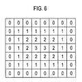
- the first filtering section 123c may set pixels corresponding to background (i.e., not blood vessel regions) as "0" and the rest of the pixels as minimum distance values from the background, as shown in FIG. 6 , to thereby form the distance transform images.
- the first filtering section 123c may be further operable to detect blood vessel border portion in the distance weighted velocity image and then perform smoothing upon the detected border portions.
- the peak restoring section 123d may be operable to restore peaks in the velocity images provided from the first filtering section 123c.
- the maximum velocity (i.e., peak) of the blood flow in the blood vessel may provide clinically important information, so that the peaks should be maintained. However, the peaks may be blurred during the smoothing, which makes the peak values lowered.
- the peak restoring section 123d may be operable to compute image differences between the velocity images provided form the image processing section 121 and the smoothed velocity images.
- the peak restoring section 123d may check peak candidates, which are regions over the image difference of "0,” and then detect regions greater than a predetermined threshold as the peak regions among the peak candidates.
- the peak restoring section 123d may be operable to restore the peaks in the smoothed velocity image by using the detected peak regions.
- the second image processing section 124 may be operable to use the mask provided from the mask forming section 122 to mask the power images sequentially provided from the image forming section 121.
- the second image processing section 124 may include a second smoothing section 124a, a second masking section 124b and a second filtering section 124c.
- the second smoothing section 124a may be operable to perform smoothing upon the power images.
- the smoothing may be performed through mean filtering, Gaussian filtering, median filtering, low pass filtering, graph regularization and the like.
- the second masking section 124b may use the mask provided from the mask forming section 122 to mask the smoothed power images.
- the second masking section 124b may be operable to use the mask to set regions corresponding to the blood vessels for each of pixels of the respective power images as "1" and regions except for the blood vessel regions as "0.”
- the second filtering section 124c may be operable to apply distance weighting to the masked power image and then perform border smoothing thereupon.
- the distance weighting may be performed such that the powers of the blood flow at blood vessel border portions are indicated lower than those at the center portion of the blood flow.
- the second filtering section 124c may be operable to form distance transform images by using the masked power images.
- the second filtering section 124c may be further operable to detect blood vessel border portion in the distance weighted power images and then perform smoothing upon the detected border portions.
- the display unit 130 may include at least one of a CRT monitor, a LCD monitor, a plate display and the like.
- the display unit 130 may display the color Doppler mode images formed in the processing unit 120, i.e., velocity images and power images.
- the control unit 140 may operable to control the formation, image processing and display of the power images and the velocity images.
- instructions for performing the above method of processing the color Doppler mode image may be recorded in a computer readable medium using computer-readable instructions.
- the computer readable medium may include any types of record media, which can be read by a computer system.
- the computer readable medium may include read only memory (ROM), random access memory (RAM), CD-ROM, magnetic tape, floppy disk, optical-data recording apparatus and the like.
- the computer readable medium comprises computer executable instructions that may be configured to perform the following acts: a) transmitting and receiving ultrasound signals to and from a target object to acquire first Doppler signals; b) forming color Doppler images including power images and velocity images; c) forming a mask for detecting a region of interest by using the color Doppler images; and d) masking the power images and the velocity image by using the mask.
Landscapes
- Engineering & Computer Science (AREA)
- Physics & Mathematics (AREA)
- General Physics & Mathematics (AREA)
- Remote Sensing (AREA)
- Radar, Positioning & Navigation (AREA)
- Computer Vision & Pattern Recognition (AREA)
- Theoretical Computer Science (AREA)
- Acoustics & Sound (AREA)
- Computer Networks & Wireless Communication (AREA)
- Health & Medical Sciences (AREA)
- Life Sciences & Earth Sciences (AREA)
- Heart & Thoracic Surgery (AREA)
- Public Health (AREA)
- Medical Informatics (AREA)
- Molecular Biology (AREA)
- Surgery (AREA)
- Animal Behavior & Ethology (AREA)
- General Health & Medical Sciences (AREA)
- Biomedical Technology (AREA)
- Veterinary Medicine (AREA)
- Radiology & Medical Imaging (AREA)
- Pathology (AREA)
- Nuclear Medicine, Radiotherapy & Molecular Imaging (AREA)
- Biophysics (AREA)
- Ultra Sonic Daignosis Equipment (AREA)
Abstract
Description
- The present application claims priority from Korean Patent Application No.
10-10-2009-0038474 filed on April 30, 2009 - The present disclosure relates to ultrasound image processing, and more particularly to color Doppler mode image processing in an ultrasound system.
- Recently, an ultrasound system has been extensively used in the medical field due to its non-invasive and non-destructive nature. Modem high-performance ultrasound imaging diagnostic systems and techniques are typically used to produce two- or three-dimensional ultrasound images of internal features of patients. To provide the ultrasound images, the ultrasound system operates in various image modes such as a brightness mode, a Doppler mode and the like to acquire ultrasound images for diagnosis.
- In the Doppler mode, the ultrasound system provides a color Doppler mode image visualizing velocities of moving objects such as blood flow, heart, etc. The color Doppler mode image includes a power image visualizing powers of Doppler signals as 2-dimensional distribution and a velocity image visualizing velocities of the moving objects, which may be computed from the Doppler signals, as 2-dimensional distribution. The color Doppler mode image may visualize the blood flow in real time and a wide range from the blood flow of a high velocity in a large vessel to the blood flow of a low velocity in a small vessel.
- Conventionally, smoothing has been carried out upon the velocity image for enhancement. However, since the blood flow on the velocity image may be extended to the vessel region due to the smoothing, bleeding, which shows blood escape from the real vessel on the velocity image, may be caused. Further, a loss of small vessels may occur. Also, the connectivity loss, i.e., portions of vessel are cut in the velocity image, may be generated. The peaks of the blood flow may be important clinical information in the velocity image. However, the peak loss, i.e., peaks of the blood flow are disappeared in the velocity image, may be also generated due to the smoothing thereupon.
- Further, the effectiveness of pixels in the power image is determined through the fixed thresholding method. However, since the power of blood flow varies according to the heartbeat, the vascular collapse, i.e., the blood vessel region is collapsed in the power image, may occur.
- Embodiments for processing a color Doppler mode image in an ultrasound system are provided. The ultrasound system comprises: a Doppler signal acquisition unit configured to transmit and receive ultrasound signals to and from a target object to acquire first Doppler signals; and a processing unit configured to form color Doppler images including power images and velocity images and a mask for detecting a region of interest by using the color flow images, the processing unit being further configured to mask the power images and the velocity image by using the mask.
- In another embodiment, a method of processing a color Doppler mode image in an ultrasound system including a Doppler signal acquisition unit and a processing unit, comprises: a) at the Doppler signal acquisition unit, transmitting and receiving ultrasound signals to and from a target object to acquire first Doppler signals; b) at the processing unit, forming color Doppler images including power images and velocity images; c) at the processing unit, forming a mask for detecting a region of interest by using the color Doppler images; and d) at the processing unit, masking the power images and the velocity image by using the mask.
- The Summary is provided to introduce a selection of concepts in a simplified form that are further described below in the Detailed Description. This Summary is not intended to identify key or essential features of the claimed subject matter, nor is it intended to be used in determining the scope of the claimed subject matter.
-
- FIG. 1
- is a block diagram showing an illustrative embodiment of an ultrasound system.
- FIG. 2
- is a block diagram showing an illustrative embodiment of a signal acquisition unit in
FIG. 1 . - FIG. 3
- is a block diagram showing an illustrative embodiment of a processing unit in
FIG. 1 . - FIG. 4
- is an exemplary diagram showing an example of a graph of mean powers for power images and formation of compound images.
- FIG. 5A
- is a diagram showing an example of setting a mask.
- FIG. 5B
- is a diagram showing an example of detecting contours of a mask.
- FIG. 5C
- is a diagram showing an example of smoothed contours of a mask.
- FIG. 5D
- is a diagram showing an example resulting from performing filling upon a mask.
- FIG. 6
- is a diagram showing an example of a distance transform image.
- A detailed description may be provided with reference to the accompanying drawings. One of ordinary skill in the art may realize that the following description is illustrative only and is not in any way limiting. Other embodiments of the present invention may readily suggest themselves to such skilled persons having the benefit of this disclosure.
- Referring to
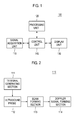
FIG. 1 , an illustrative embodiment of anultrasound system 100 is shown. As depicted therein, theultrasound system 100 may include asignal acquisition unit 110. Thesignal acquisition unit 110 may be operable to alternately transmit and receive ultrasound signals to and from a moving target object (e.g., heart, blood flow, etc). Thesignal acquisition unit 110 may acquire Doppler signals corresponding to a plurality of frames based on the received ultrasound signals. In one embodiment, the frames may include color Doppler mode image frames. -
FIG. 2 is a block diagram showing an illustrative embodiment of thesignal acquisition unit 110 inFIG. 1 . Referring toFIG. 2 , thesignal acquisition unit 110 may include a transmit (Tx)signal generating section 111. The Txsignal generating section 111 may be operable to generate a plurality of transmit signals. - The
signal acquisition unit 110 may further include anultrasound probe 112 containing a plurality of transducer elements for reciprocally converting ultrasound signals and electrical signals. Theultrasound probe 122 may be operable to transmit ultrasound signals into a target object in response to the transmit signals. Theultrasound probe 112 may be further operable to receive echo signals reflected from the target object to thereby output electrical receive signals, which are analog signals. The transmission and reception of the ultrasound signals are alternately carried out to output a plurality of electrical receive signals. - The
signal acquisition unit 110 may further include abeam forming section 113. Thebeam forming section 113 may be operable to convert the electrical receive signals into digital signals. Thebeam forming section 113 may be further operable to apply delays to the digital signals in consideration of distances between the elements and focal points, thereby outputting digital receive-focused signals. - The
signal acquisition unit 110 may further include a Dopplersignal forming section 114 that may be operable to form Doppler signals based on the digital receive-focused signals. The Doppler signals may contain power information and velocity information. TheDoppler forming section 114 may be operable to perform signal processing (e.g., gain adjustment, filtering and the like) necessary for forming the Doppler signals upon the digital receive-focused signals. - The
ultrasound system 100 may further include aprocessing unit 120 coupled to thesignal acquisition unit 110. Theprocessing unit 120 may be operable to form a color Doppler mode image based on the Doppler signals provided from thesignal acquisition unit 110. Theprocessing unit 120 may be further operable to form a mask for detecting a blood vessel region by using the color Doppler mode image and perform masking upon the color Doppler mode image. The color Doppler mode image may include a power image indicative of powers of the Doppler signals as 2-dimensional distribution and a velocity image indicative of velocities of the Doppler signals as 2-dimensional distribution. -
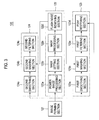
FIG. 3 is a block diagram showing an illustrative embodiment of the processing unit. Referring toFIG. 3 , theprocessing unit 120 may include animage forming section 121, amask forming section 122, a firstimage processing section 123 and a secondimage processing section 124. - The
image forming section 121 may be operable to a power image and a velocity image based on the Doppler signals provided from thesignal acquisition unit 121. Themask forming section 122 may be operable to form a mask for detecting a blood vessel region, which is a region of interest, on the power image. In one embodiment, themask forming section 122 may include a powerimage processing section 122a, amask setting section 122b, amask processing section 122c and a flashnoise removing section 122d. - The power
image processing section 122a may be operable to analyze the power images sequentially provided from theimage forming section 121 to set a reference power image. In one embodiment, a power image having a mean power greater than a predetermined threshold may be set as the reference power image. The powerimage processing section 122a may be further operable to compound power images, of which mean powers are less than the predetermined threshold, with the reference power image to thereby form compound images.
FIG. 4 shows an example of mean powers of the power images and examples of setting the reference power image to form the compound images by using the power images. Referring toFIG. 4 , if a first power image PI1 is provided, then the powerimage processing section 122a may be operable to compute a mean power of the first power image (hereinafter, referred to as "first mean power"). The powerimage processing section 122a may initially set the first power image PI1 and the first mean power as the reference power image and the reference mean power. - If a second power image PI2 is provided from the
image forming section 121, then the powerimage processing section 122a may be operable to compute the mean power of the second power image PI2 (hereinafter, referred to as "second mean power"). The power image processing section 112a may check whether the second mean power is greater than the predetermined threshold (e.g., reference mean power 0.8). If the second mean power is greater than the predetermined threshold, then the powerimage processing section 122a may be operable to set the second power image PI2 as a new reference power image. - If a third power image PI3 is provided from the
image forming section 121, then the powerimage processing section 122a may be operable to compute the mean power of the third power image PI3 (hereinafter, referred to as "third mean power"). The powerimage processing section 122a may check whether the third mean power is greater than the predetermined threshold (e.g., reference mean power 0.8). If the third mean power is greater than the predetermined threshold, then the powerimage processing section 122a may be operable to set the third power image PI3 as a new reference power image. - If a fourth power image PI4 is provided from the
image forming section 121, then the powerimage processing section 122a may be operable to compute the mean power of the fourth power image PI4 (hereinafter, referred to as "fourth mean power"). The powerimage processing section 122a may check whether the fourth mean power is greater than the predetermined threshold (e.g., reference mean power 0.8). If the fourth mean power is less than the predetermined threshold, then the powerimage processing section 122a may be operable to compound the fourth power image PI4 and the reference power image, thereby forming a compound image CI4. In one embodiment, since the power image having relatively low mean power is compounded with the reference power image, it may be prevented that the blood vessel region is indicated as a small region on the power image due to the low mean power. - If fifth to eighth power images PI5-PI8 are provided from the
image forming section 121, then the powerimage processing section 122a may be operable to compute mean powers of the fifth to eighth power images PI5-PI8 (hereinafter, referred to as "fifth to eighth mean powers"). The powerimage processing section 122a may compare the fifth to eighth mean powers with the predetermined threshold (e.g., reference mean power 0.8). If the fifth to eighth mean powers are less than the predetermined threshold, then the powerimage processing section 122a may be operable to compound the respective fifth to eighth power images PI5-PI8 with the reference power image. - If a ninth power image PI9 is provided from the
image forming section 121, then the powerimage processing section 122a may be operable to compute the mean power of the ninth power image PI9 (hereinafter, referred to as "ninth mean power"). The powerimage processing section 122a may check whether the ninth mean power is greater than the predetermined threshold (e.g., reference mean power 0.8). If the ninth mean power is greater than the predetermined threshold, then the powerimage processing section 122a may be operable to set the ninth power image PI9 as a new reference power image. - If tenth to twelfth power images PI10-PI12 are provided from the
image forming section 121, then the powerimage processing section 122a may be operable to compute mean powers of the tenth to twelfth power images PI10-PI12 (hereinafter, referred to as "tenth to twelfth mean powers"). The powerimage processing section 122a may compare each of the tenth to twelfth mean powers with the predetermined threshold (e.g., reference mean power 0.8). If the tenth to twelfth mean powers are less than the predetermined threshold, then the powerimage processing section 122a may be operable to compound each of the tenth to twelfth power images PI10-PI12 with the reference power image PI9, thereby forming compound images CI10-CI12, - The
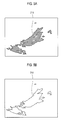
mask setting section 122b may be operable to set a region of interest, i.e., a mask for detecting a blood vessel region on each of the reference power images PI1-PI3 and PI9 and the compound images CI4-CI8 and CI10-CI12, as shown inFIG. 5A . The mask may include one or more sub regions. In one embodiment, the mask may be set by using various well-known methods, such as a thresholding method, an area expanding method, an area segmenting method, a contour extracting method, a graph method, a watershed method, and the like. - The
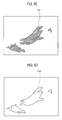
mask processing section 122c may be operable to detect contours of the mask set in themask setting section 122b, as illustrated inFIG. 5B . In one embodiment, by way of non-limiting example, the contours may be detected by using contour following, mathematical morphological operation and the like. Themask processing section 122c may be operable to perform smoothing upon the detected contours of the mask, as shown inFIG. 5C . The smoothing may be performed through at least one of Fourier descriptor based algorithm, chain codes, active contour and the like. Themask processing section 122c may be further operable to perform filling upon the smoothed mask, as shown inFIG. 5D . - The flash
noise removing section 122d may be operable to remove flash noises from the mask provided from themask processing section 122c. The flash noises may occur due to muscles neighboring to the blood vessels, heart muscles and the like whose moving velocities are slower than those of the blood flows while their moving powers are greater than those of the blood flows. The flash noises may be appeared and disappeared in a flash. In one embodiment, the flashnoise removing section 122d may be operable to perform region labeling upon the mask of the frame (reference power image or compound image) to assign a specific index to each of the sub regions in the mask. The flashnoise removing section 122d may compare the mask of the current frame with the masks of the predetermined number of the previous frames (e.g., 3 frames). If the indices in the mask of the current frame are not identical to those of the respective sub regions of the predetermined number of the previous frames, then the flashnoise removing section 122d may determine the different indexed sub region(s) in the mask of the current frame as the flash noises to thereby remove them. In another embodiment, the flashnoise removing section 122d may check whether each of the sub regions in the mask is effective as the blood vessel. The flashnoise removing section 122d may remove the sub regions, which do not have the effective values. The effectiveness may be determined by checking whether the maximum value of pixels in each sub region in the mask is greater than a predetermined value. When the maximum value of pixels in the sub region is less than the predetermined value, the corresponding region sub may be determined as the noise. Also, the effectiveness may be determined by checking whether the contours of the sub regions in the mask are flat over a predetermined portion. - The first
image processing section 123 may use the mask provided from themask forming section 122 to mask the velocity images, which may be sequentially provided form theimage forming section 121. Referring toFIG. 3 , the firstimage processing section 123 may include afirst smoothing section 123a, afirst masking section 123b, afirst filtering section 123c and apeak restoring section 123d. - The
first smoothing section 123a may be operable to perform smoothing upon the velocity images. In one embodiment, by way of non-limiting example, the smoothing may be carried out through one of the mean filtering, Gaussian filtering, median filtering, low pass filtering, graph regularization and the like. - The
first masking section 123b may use the mask provided from themask forming section 122 to mask the smoothed velocity images. Thefirst masking section 123b may be operable to use the mask to set regions corresponding to the blood vessels for each of pixels of the respective velocity images as "1" and regions except for the blood vessel regions as "0." - The
first filtering section 123c may be operable to apply distance weighting to the masked velocity images and then perform border smoothing thereupon. The distance weighting may be performed such that the velocities of the blood flow at blood vessel border portions are indicated slower than those at the center portion of the blood flow. - The
first filtering section 123c may be operable to form distance transform images by using the masked velocity images. Thefirst filtering section 123c may set pixels corresponding to background (i.e., not blood vessel regions) as "0" and the rest of the pixels as minimum distance values from the background, as shown inFIG. 6 , to thereby form the distance transform images. Distance weighting corresponding to the pixels of the distance transform image may be expressed as a function of the pixels. In one embodiment, the distance weighting may be defined as w(i)=min(i*0.2+0.6, 1), wherein i represents a pixel value in the distance transform image. Thus, if a pixel value of the smoothed velocity image is f(x, y), this pixel value may be transformed to f(x, y)*w(f(x, y)). Thefirst filtering section 123c may be further operable to detect blood vessel border portion in the distance weighted velocity image and then perform smoothing upon the detected border portions. - The
peak restoring section 123d may be operable to restore peaks in the velocity images provided from thefirst filtering section 123c. The maximum velocity (i.e., peak) of the blood flow in the blood vessel may provide clinically important information, so that the peaks should be maintained. However, the peaks may be blurred during the smoothing, which makes the peak values lowered. Thus, thepeak restoring section 123d may be operable to compute image differences between the velocity images provided form theimage processing section 121 and the smoothed velocity images. Thepeak restoring section 123d may check peak candidates, which are regions over the image difference of "0," and then detect regions greater than a predetermined threshold as the peak regions among the peak candidates. Thepeak restoring section 123d may be operable to restore the peaks in the smoothed velocity image by using the detected peak regions. - The second
image processing section 124 may be operable to use the mask provided from themask forming section 122 to mask the power images sequentially provided from theimage forming section 121. In one embodiment, the secondimage processing section 124 may include asecond smoothing section 124a, asecond masking section 124b and asecond filtering section 124c. - If the power images are provided from the
image forming section 121, thesecond smoothing section 124a may be operable to perform smoothing upon the power images. In one embodiment, the smoothing may be performed through mean filtering, Gaussian filtering, median filtering, low pass filtering, graph regularization and the like. - The
second masking section 124b may use the mask provided from themask forming section 122 to mask the smoothed power images. Thesecond masking section 124b may be operable to use the mask to set regions corresponding to the blood vessels for each of pixels of the respective power images as "1" and regions except for the blood vessel regions as "0." - The
second filtering section 124c may be operable to apply distance weighting to the masked power image and then perform border smoothing thereupon. The distance weighting may be performed such that the powers of the blood flow at blood vessel border portions are indicated lower than those at the center portion of the blood flow. Thesecond filtering section 124c may be operable to form distance transform images by using the masked power images. Thesecond filtering section 124c may be further operable to detect blood vessel border portion in the distance weighted power images and then perform smoothing upon the detected border portions. - Referring back to
FIG. 1 , thedisplay unit 130 may include at least one of a CRT monitor, a LCD monitor, a plate display and the like. Thedisplay unit 130 may display the color Doppler mode images formed in theprocessing unit 120, i.e., velocity images and power images. Thecontrol unit 140 may operable to control the formation, image processing and display of the power images and the velocity images. - In another embodiment, instructions for performing the above method of processing the color Doppler mode image may be recorded in a computer readable medium using computer-readable instructions. The computer readable medium may include any types of record media, which can be read by a computer system. The computer readable medium may include read only memory (ROM), random access memory (RAM), CD-ROM, magnetic tape, floppy disk, optical-data recording apparatus and the like. The computer readable medium comprises computer executable instructions that may be configured to perform the following acts: a) transmitting and receiving ultrasound signals to and from a target object to acquire first Doppler signals; b) forming color Doppler images including power images and velocity images; c) forming a mask for detecting a region of interest by using the color Doppler images; and d) masking the power images and the velocity image by using the mask.
- Although embodiments have been described with reference to a number of illustrative embodiments thereof, it should be understood that numerous other modifications and embodiments can be devised by those skilled in the art that will fall within the spirit and scope of the principles of this disclosure. More particularly, numerous variations and modifications are possible in the component parts and/or arrangements of the subject combination arrangement within the scope of the disclosure, the drawings and the appended claims. In addition to variations and modifications in the component parts and/or arrangements, alternative uses will also be apparent to those skilled in the art.
Claims (15)
- An ultrasound system, comprising:a Doppler signal acquisition unit configured to transmit and receive ultrasound signals to and from a target object to acquire first Doppler signals; anda processing unit configured to form color Doppler images including power images and velocity images and a mask for detecting a region of interest by using the color flow images, the processing unit being further configured to mask the power images and the velocity image by using the mask.
- The ultrasound system of Claim 1, wherein the processing unit includes:an image forming section configured to form the power images and the velocity images;a mask forming section configured to form a mask by using the power image;a first image processing section configured to mask the velocity images by using the mask; anda second image processing section configured to mask the power images by using the mask.
- The ultrasound system of Claim 2, wherein the mask forming section includes:a power image processing section configured to analyze the power images to set a reference power image whose mean power is greater than a predetermined threshold, and to compound the reference power image with power images whose mean power is less than the predetermined threshold to form compound images;a mask setting section configured to set the mask for detecting the region of interest by using the reference power image and the compound images; anda mask processing section configured to detect contours of the mask, perform smoothing upon the detected contours, and perform filling upon the smoothed mask.
- The ultrasound system of Claim 3, wherein the predetermined threshold is a value obtained by multiplying the reference mean power by a predetermined value.
- The ultrasound system of Claim 4, wherein the mask forming section includes a flash noise removing section to remove flash noises in the mask.
- The ultrasound system of Claim 4, wherein the power image processing section is configured to:compute a first mean power of a first power image provided from the image forming section to set a reference mean power;set the first power image as a reference power image;compute an ith mean power of an ith power image provided from the image processing section, wherein i is a positive integer greater than 1;compare the ith mean power with a predetermined threshold;set, when the ith mean power is greater than the predetermined threshold, the ith mean power as a new reference mean power and set the ith power image as a new reference power image; andcompound, when the ith mean power is less than the predetermined threshold, the ith power image to the reference power image.
- The ultrasound system of Claim 2, wherein the first image processing section includes:a first smoothing section configured to perform smoothing upon the velocity images;a first masking section configured to mask the smoothed velocity images by using the mask;a first filtering section configured to perform distance weighting and border smoothing upon the masked velocity images; anda peak restoring section configured to obtain difference image between the velocity image provided from the image processing section and the distance-weighted and border-smoothed velocity images, detect peak regions by using the difference images, and restore peaks of the distance-weighted and border-smoothed velocity images by using the detected peak regions.
- The ultrasound system of Claim 2, wherein the second image processing section includes:a second smoothing section configured to perform smoothing upon the power images;a second masking section configured to mask the smoothed power images; anda second filtering section configured to perform distance weighting and border smoothing upon the masked power images.
- A method of processing a color Doppler mode image in an ultrasound system including a Doppler signal acquisition unit and a processing unit, comprising:a) at the Doppler signal acquisition unit, transmitting and receiving ultrasound signals to and from a target object to acquire first Doppler signals;b) at the processing unit, forming color Doppler images including power images and velocity images;c) at the processing unit, forming a mask for detecting a region of interest by using the color Doppler images; andd) at the processing unit, masking the power images and the velocity image by using the mask.
- The method of Claim 9, wherein the c) includes:c1) analyzing the power images to set a reference power image whose mean power is greater than a predetermined threshold, and compounding the reference power image with power images whose mean power is less than the predetermined threshold to form compound images;c2) setting the mask for detecting the region of interest by using the reference power image and the compound images; andc3) detect contours of the mask to perform smoothing upon the detected contours; andc4) performing filling upon the smoothed mask.
- The method of Claim 10, wherein the c) further includes removing flash noises from the mask.
- The method of Claim 10, wherein the predetermined threshold is a value obtained by multiplying the reference mean power by a predetermined value.
- The method of Claim 10, wherein the c1) includes:computing a first mean power of a first power image provided from the image forming section to set a reference mean power;setting the first power image as a reference power image;computing an ith mean power of an ith power image provided from the image processing section, wherein i is a positive integer greater than 1;comparing the ith mean power with a predetermined threshold;setting, when the ith mean power is greater than the predetermined threshold, the ith mean power as a new reference mean power and set the ith power image as a new reference power image; andcompounding, when the ith mean power is less than the predetermined threshold, the ith power image to the reference power image.
- The method of Claim 9, wherein the d) includes:performing smoothing upon the velocity images;masking the smoothed velocity images by using the mask;performing distance weighting and border smoothing upon the masked velocity images;obtaining difference image between the velocity image provided from the image processing section and the distance-weighted and border-smoothed velocity images;detecting peak regions by using the difference images; andrestoring peaks of the distance-weighted and border smoothed velocity images by using the detected peak regions.
- The method of Claim 9, wherein the d) include:performing smoothing upon the power images;masking the smoothed power images; andperforming distance weighting and border smoothing upon the masked power images.
Applications Claiming Priority (1)
| Application Number | Priority Date | Filing Date | Title |
|---|---|---|---|
| KR1020090038474A KR101138613B1 (en) | 2009-04-30 | 2009-04-30 | Ultrasound system and method for processing color doppler mode image |
Publications (2)
| Publication Number | Publication Date |
|---|---|
| EP2249175A1 true EP2249175A1 (en) | 2010-11-10 |
| EP2249175B1 EP2249175B1 (en) | 2014-06-11 |
Family
ID=42320947
Family Applications (1)
| Application Number | Title | Priority Date | Filing Date |
|---|---|---|---|
| EP10160682.0A Active EP2249175B1 (en) | 2009-04-30 | 2010-04-22 | Color doppler mode image processing in an ultrasound system |
Country Status (4)
| Country | Link |
|---|---|
| US (1) | US8500646B2 (en) |
| EP (1) | EP2249175B1 (en) |
| JP (1) | JP5576703B2 (en) |
| KR (1) | KR101138613B1 (en) |
Families Citing this family (7)
| Publication number | Priority date | Publication date | Assignee | Title |
|---|---|---|---|---|
| KR101121548B1 (en) * | 2009-12-07 | 2012-03-06 | 삼성메디슨 주식회사 | Ultrasonic Diagnostic Device |
| KR101313220B1 (en) * | 2010-11-23 | 2013-09-30 | 삼성메디슨 주식회사 | Ultrasound system and method for providing color doppler mode image based on qualification curve |
| JP5972691B2 (en) * | 2012-07-09 | 2016-08-17 | 東芝メディカルシステムズ株式会社 | Ultrasonic diagnostic apparatus, image processing apparatus, and program |
| KR101610877B1 (en) | 2014-04-28 | 2016-04-21 | 주식회사 웨이전스 | Module for Processing Ultrasonic Signal Based on Spatial Coherence and Method for Processing Ultrasonic Signal |
| US11030748B2 (en) * | 2016-10-28 | 2021-06-08 | Koninklijke Philips N.V. | Automatic CT detection and visualization of active bleeding and blood extravasation |
| CN110313939B (en) * | 2019-08-01 | 2020-12-11 | 无锡海斯凯尔医学技术有限公司 | Tissue region-of-interest positioning method, device, equipment and storage medium |
| US20220061810A1 (en) * | 2020-08-25 | 2022-03-03 | Clarius Mobile Health Corp. | Systems and methods for placing a gate and/or a color box during ultrasound imaging |
Citations (6)
| Publication number | Priority date | Publication date | Assignee | Title |
|---|---|---|---|---|
| EP0871043A2 (en) | 1997-04-08 | 1998-10-14 | EndoSonics Corporation | A method and apparatus for creating a color blood flow image based upon ultrasonic echo signals received by an intravascular ultrasound imaging probe |
| US5860929A (en) * | 1996-06-07 | 1999-01-19 | The Regents Of The University Of Michigan | Fractional moving blood volume estimation with power doppler ultrasound |
| US6217520B1 (en) * | 1998-12-02 | 2001-04-17 | Acuson Corporation | Diagnostic medical ultrasound system and method for object of interest extraction |
| US20030181814A1 (en) * | 2002-03-19 | 2003-09-25 | Ting-Lan Ji | System and method for post-processing ultrasound color doppler imaging |
| US20040138567A1 (en) * | 2002-12-27 | 2004-07-15 | Yd, Ltd. | Method of analyzing and displaying blood volume using myocardial blood volume map |
| US20060116582A1 (en) * | 2004-11-22 | 2006-06-01 | Tetsuya Yoshida | Ultrasonic diagnosis apparatus and ultrasonic diagnosis method |
Family Cites Families (7)
| Publication number | Priority date | Publication date | Assignee | Title |
|---|---|---|---|---|
| AR228821A1 (en) * | 1982-02-22 | 1983-04-15 | Dassler Puma Sportschuh | SPORTS SHOES |
| JPH02268748A (en) * | 1989-04-11 | 1990-11-02 | Yokogawa Medical Syst Ltd | Ultrasonic blood flow imaging apparatus |
| JPH1075955A (en) * | 1996-07-11 | 1998-03-24 | Fujitsu Ltd | Ultrasonic diagnostic device |
| JP4574768B2 (en) * | 1998-11-16 | 2010-11-04 | 株式会社東芝 | 3D ultrasonic diagnostic equipment |
| US6352509B1 (en) * | 1998-11-16 | 2002-03-05 | Kabushiki Kaisha Toshiba | Three-dimensional ultrasonic diagnosis apparatus |
| JP2008154891A (en) * | 2006-12-26 | 2008-07-10 | Ge Medical Systems Global Technology Co Llc | Color doppler apparatus and ultrasonic imaging apparatus |
| WO2009013686A2 (en) * | 2007-07-26 | 2009-01-29 | Koninklijke Philips Electronics, N.V. | Systems and methods for automated image selection in doppler ultrasound imaging systems |
-
2009
- 2009-04-30 KR KR1020090038474A patent/KR101138613B1/en active IP Right Grant
-
2010
- 2010-04-22 EP EP10160682.0A patent/EP2249175B1/en active Active
- 2010-04-26 US US12/767,300 patent/US8500646B2/en active Active
- 2010-04-28 JP JP2010104141A patent/JP5576703B2/en not_active Expired - Fee Related
Patent Citations (6)
| Publication number | Priority date | Publication date | Assignee | Title |
|---|---|---|---|---|
| US5860929A (en) * | 1996-06-07 | 1999-01-19 | The Regents Of The University Of Michigan | Fractional moving blood volume estimation with power doppler ultrasound |
| EP0871043A2 (en) | 1997-04-08 | 1998-10-14 | EndoSonics Corporation | A method and apparatus for creating a color blood flow image based upon ultrasonic echo signals received by an intravascular ultrasound imaging probe |
| US6217520B1 (en) * | 1998-12-02 | 2001-04-17 | Acuson Corporation | Diagnostic medical ultrasound system and method for object of interest extraction |
| US20030181814A1 (en) * | 2002-03-19 | 2003-09-25 | Ting-Lan Ji | System and method for post-processing ultrasound color doppler imaging |
| US20040138567A1 (en) * | 2002-12-27 | 2004-07-15 | Yd, Ltd. | Method of analyzing and displaying blood volume using myocardial blood volume map |
| US20060116582A1 (en) * | 2004-11-22 | 2006-06-01 | Tetsuya Yoshida | Ultrasonic diagnosis apparatus and ultrasonic diagnosis method |
Also Published As
| Publication number | Publication date |
|---|---|
| US8500646B2 (en) | 2013-08-06 |
| KR20100119387A (en) | 2010-11-09 |
| US20100280383A1 (en) | 2010-11-04 |
| JP2010259794A (en) | 2010-11-18 |
| KR101138613B1 (en) | 2012-04-26 |
| JP5576703B2 (en) | 2014-08-20 |
| EP2249175B1 (en) | 2014-06-11 |
Similar Documents
| Publication | Publication Date | Title |
|---|---|---|
| EP2249175B1 (en) | Color doppler mode image processing in an ultrasound system | |
| CN107361791B (en) | Rapid super-resolution blood flow imaging method | |
| EP1101128B1 (en) | Method and apparatus for spatial and temporal filtering of intravascular ultrasonic image data | |
| Saini et al. | Ultrasound imaging and image segmentation in the area of ultrasound: a review | |
| KR101121396B1 (en) | System and method for providing 2-dimensional ct image corresponding to 2-dimensional ultrasound image | |
| US9934554B2 (en) | Ultrasound imaging method/technique for speckle reduction/suppression in an improved ultra sound imaging system | |
| KR101121353B1 (en) | System and method for providing 2-dimensional ct image corresponding to 2-dimensional ultrasound image | |
| US9585636B2 (en) | Ultrasonic diagnostic apparatus, medical image processing apparatus, and medical image processing method | |
| CN109767400B (en) | Ultrasonic image speckle noise removing method for guiding trilateral filtering | |
| US20060098853A1 (en) | Segmentation tool for identifying flow regions in an image system | |
| JP7405950B2 (en) | A method for performing high spatiotemporal resolution ultrasound imaging of microvasculature | |
| US9081097B2 (en) | Component frame enhancement for spatial compounding in ultrasound imaging | |
| Tay et al. | A wavelet thresholding method to reduce ultrasound artifacts | |
| CN111265246B (en) | Ultrasonic color imaging processing method and device | |
| JP2005193017A (en) | Method and system for classifying diseased part of mamma | |
| EP3905960B1 (en) | Systems and methods for contrast enhanced imaging | |
| CN110800019A (en) | Method and system for composite ultrasound image generation | |
| US20060030777A1 (en) | T-statistic method for suppressing artifacts in blood vessel ultrasonic imaging | |
| CN114419016A (en) | Ultrasonic super-resolution method and system for differential diagnosis of benign and malignant thyroid nodules | |
| Mendizabal-Ruiz et al. | Probabilistic segmentation of the lumen from intravascular ultrasound radio frequency data | |
| Kleckler et al. | Characterization of Heterogeneous Perfusion in Contrast-Enhanced Ultrasound | |
| Anand et al. | Comparing Focused-Tracked and Plane Wave-Tracked ARFI Log (VoA) In Silico and in Application to Human Carotid Atherosclerotic Plaque, Ex Vivo | |
| JP6731369B2 (en) | Ultrasonic diagnostic device and program | |
| El Harake et al. | Cardiac strain imaging artifact detection and suppression with minimum variance beamforming and svd filtering | |
| Piepenbrock et al. | Performance of Foreground-Background Separation Algorithms for the Detection of Microbubbles in Super-Resolution Imaging |
Legal Events
| Date | Code | Title | Description |
|---|---|---|---|
| PUAI | Public reference made under article 153(3) epc to a published international application that has entered the european phase |
Free format text: ORIGINAL CODE: 0009012 |
|
| AK | Designated contracting states |
Kind code of ref document: A1 Designated state(s): AT BE BG CH CY CZ DE DK EE ES FI FR GB GR HR HU IE IS IT LI LT LU LV MC MK MT NL NO PL PT RO SE SI SK SM TR |
|
| AX | Request for extension of the european patent |
Extension state: AL BA ME RS |
|
| 17P | Request for examination filed |
Effective date: 20110509 |
|
| 17Q | First examination report despatched |
Effective date: 20110630 |
|
| GRAP | Despatch of communication of intention to grant a patent |
Free format text: ORIGINAL CODE: EPIDOSNIGR1 |
|
| INTG | Intention to grant announced |
Effective date: 20131209 |
|
| GRAS | Grant fee paid |
Free format text: ORIGINAL CODE: EPIDOSNIGR3 |
|
| GRAA | (expected) grant |
Free format text: ORIGINAL CODE: 0009210 |
|
| AK | Designated contracting states |
Kind code of ref document: B1 Designated state(s): AT BE BG CH CY CZ DE DK EE ES FI FR GB GR HR HU IE IS IT LI LT LU LV MC MK MT NL NO PL PT RO SE SI SK SM TR |
|
| REG | Reference to a national code |
Ref country code: GB Ref legal event code: FG4D |
|
| REG | Reference to a national code |
Ref country code: CH Ref legal event code: EP |
|
| REG | Reference to a national code |
Ref country code: IE Ref legal event code: FG4D |
|
| REG | Reference to a national code |
Ref country code: AT Ref legal event code: REF Ref document number: 672512 Country of ref document: AT Kind code of ref document: T Effective date: 20140715 |
|
| REG | Reference to a national code |
Ref country code: DE Ref legal event code: R096 Ref document number: 602010016579 Country of ref document: DE Effective date: 20140724 |
|
| RAP2 | Party data changed (patent owner data changed or rights of a patent transferred) |
Owner name: SAMSUNG MEDISON CO., LTD. |
|
| REG | Reference to a national code |
Ref country code: NL Ref legal event code: T3 |
|
| RAP2 | Party data changed (patent owner data changed or rights of a patent transferred) |
Owner name: SAMSUNG MEDISON CO., LTD. |
|
| PG25 | Lapsed in a contracting state [announced via postgrant information from national office to epo] |
Ref country code: GR Free format text: LAPSE BECAUSE OF FAILURE TO SUBMIT A TRANSLATION OF THE DESCRIPTION OR TO PAY THE FEE WITHIN THE PRESCRIBED TIME-LIMIT Effective date: 20140912 Ref country code: LT Free format text: LAPSE BECAUSE OF FAILURE TO SUBMIT A TRANSLATION OF THE DESCRIPTION OR TO PAY THE FEE WITHIN THE PRESCRIBED TIME-LIMIT Effective date: 20140611 Ref country code: NO Free format text: LAPSE BECAUSE OF FAILURE TO SUBMIT A TRANSLATION OF THE DESCRIPTION OR TO PAY THE FEE WITHIN THE PRESCRIBED TIME-LIMIT Effective date: 20140911 Ref country code: FI Free format text: LAPSE BECAUSE OF FAILURE TO SUBMIT A TRANSLATION OF THE DESCRIPTION OR TO PAY THE FEE WITHIN THE PRESCRIBED TIME-LIMIT Effective date: 20140611 |
|
| REG | Reference to a national code |
Ref country code: AT Ref legal event code: MK05 Ref document number: 672512 Country of ref document: AT Kind code of ref document: T Effective date: 20140611 |
|
| REG | Reference to a national code |
Ref country code: LT Ref legal event code: MG4D |
|
| PG25 | Lapsed in a contracting state [announced via postgrant information from national office to epo] |
Ref country code: LV Free format text: LAPSE BECAUSE OF FAILURE TO SUBMIT A TRANSLATION OF THE DESCRIPTION OR TO PAY THE FEE WITHIN THE PRESCRIBED TIME-LIMIT Effective date: 20140611 Ref country code: SE Free format text: LAPSE BECAUSE OF FAILURE TO SUBMIT A TRANSLATION OF THE DESCRIPTION OR TO PAY THE FEE WITHIN THE PRESCRIBED TIME-LIMIT Effective date: 20140611 Ref country code: HR Free format text: LAPSE BECAUSE OF FAILURE TO SUBMIT A TRANSLATION OF THE DESCRIPTION OR TO PAY THE FEE WITHIN THE PRESCRIBED TIME-LIMIT Effective date: 20140611 |
|
| PG25 | Lapsed in a contracting state [announced via postgrant information from national office to epo] |
Ref country code: RO Free format text: LAPSE BECAUSE OF FAILURE TO SUBMIT A TRANSLATION OF THE DESCRIPTION OR TO PAY THE FEE WITHIN THE PRESCRIBED TIME-LIMIT Effective date: 20140611 Ref country code: CZ Free format text: LAPSE BECAUSE OF FAILURE TO SUBMIT A TRANSLATION OF THE DESCRIPTION OR TO PAY THE FEE WITHIN THE PRESCRIBED TIME-LIMIT Effective date: 20140611 Ref country code: ES Free format text: LAPSE BECAUSE OF FAILURE TO SUBMIT A TRANSLATION OF THE DESCRIPTION OR TO PAY THE FEE WITHIN THE PRESCRIBED TIME-LIMIT Effective date: 20140611 Ref country code: PT Free format text: LAPSE BECAUSE OF FAILURE TO SUBMIT A TRANSLATION OF THE DESCRIPTION OR TO PAY THE FEE WITHIN THE PRESCRIBED TIME-LIMIT Effective date: 20141013 Ref country code: EE Free format text: LAPSE BECAUSE OF FAILURE TO SUBMIT A TRANSLATION OF THE DESCRIPTION OR TO PAY THE FEE WITHIN THE PRESCRIBED TIME-LIMIT Effective date: 20140611 Ref country code: SK Free format text: LAPSE BECAUSE OF FAILURE TO SUBMIT A TRANSLATION OF THE DESCRIPTION OR TO PAY THE FEE WITHIN THE PRESCRIBED TIME-LIMIT Effective date: 20140611 |
|
| PG25 | Lapsed in a contracting state [announced via postgrant information from national office to epo] |
Ref country code: IS Free format text: LAPSE BECAUSE OF FAILURE TO SUBMIT A TRANSLATION OF THE DESCRIPTION OR TO PAY THE FEE WITHIN THE PRESCRIBED TIME-LIMIT Effective date: 20141011 Ref country code: AT Free format text: LAPSE BECAUSE OF FAILURE TO SUBMIT A TRANSLATION OF THE DESCRIPTION OR TO PAY THE FEE WITHIN THE PRESCRIBED TIME-LIMIT Effective date: 20140611 Ref country code: PL Free format text: LAPSE BECAUSE OF FAILURE TO SUBMIT A TRANSLATION OF THE DESCRIPTION OR TO PAY THE FEE WITHIN THE PRESCRIBED TIME-LIMIT Effective date: 20140611 |
|
| REG | Reference to a national code |
Ref country code: DE Ref legal event code: R097 Ref document number: 602010016579 Country of ref document: DE |
|
| PLBE | No opposition filed within time limit |
Free format text: ORIGINAL CODE: 0009261 |
|
| STAA | Information on the status of an ep patent application or granted ep patent |
Free format text: STATUS: NO OPPOSITION FILED WITHIN TIME LIMIT |
|
| PG25 | Lapsed in a contracting state [announced via postgrant information from national office to epo] |
Ref country code: DK Free format text: LAPSE BECAUSE OF FAILURE TO SUBMIT A TRANSLATION OF THE DESCRIPTION OR TO PAY THE FEE WITHIN THE PRESCRIBED TIME-LIMIT Effective date: 20140611 |
|
| 26N | No opposition filed |
Effective date: 20150312 |
|
| REG | Reference to a national code |
Ref country code: DE Ref legal event code: R097 Ref document number: 602010016579 Country of ref document: DE Effective date: 20150312 |
|
| PG25 | Lapsed in a contracting state [announced via postgrant information from national office to epo] |
Ref country code: BE Free format text: LAPSE BECAUSE OF FAILURE TO SUBMIT A TRANSLATION OF THE DESCRIPTION OR TO PAY THE FEE WITHIN THE PRESCRIBED TIME-LIMIT Effective date: 20140611 |
|
| PG25 | Lapsed in a contracting state [announced via postgrant information from national office to epo] |
Ref country code: SI Free format text: LAPSE BECAUSE OF FAILURE TO SUBMIT A TRANSLATION OF THE DESCRIPTION OR TO PAY THE FEE WITHIN THE PRESCRIBED TIME-LIMIT Effective date: 20140611 |
|
| PG25 | Lapsed in a contracting state [announced via postgrant information from national office to epo] |
Ref country code: MC Free format text: LAPSE BECAUSE OF FAILURE TO SUBMIT A TRANSLATION OF THE DESCRIPTION OR TO PAY THE FEE WITHIN THE PRESCRIBED TIME-LIMIT Effective date: 20140611 Ref country code: LU Free format text: LAPSE BECAUSE OF FAILURE TO SUBMIT A TRANSLATION OF THE DESCRIPTION OR TO PAY THE FEE WITHIN THE PRESCRIBED TIME-LIMIT Effective date: 20150422 |
|
| REG | Reference to a national code |
Ref country code: CH Ref legal event code: PL |
|
| GBPC | Gb: european patent ceased through non-payment of renewal fee |
Effective date: 20150422 |
|
| REG | Reference to a national code |
Ref country code: IE Ref legal event code: MM4A |
|
| PG25 | Lapsed in a contracting state [announced via postgrant information from national office to epo] |
Ref country code: CH Free format text: LAPSE BECAUSE OF NON-PAYMENT OF DUE FEES Effective date: 20150430 Ref country code: LI Free format text: LAPSE BECAUSE OF NON-PAYMENT OF DUE FEES Effective date: 20150430 Ref country code: GB Free format text: LAPSE BECAUSE OF NON-PAYMENT OF DUE FEES Effective date: 20150422 |
|
| REG | Reference to a national code |
Ref country code: FR Ref legal event code: PLFP Year of fee payment: 7 |
|
| PG25 | Lapsed in a contracting state [announced via postgrant information from national office to epo] |
Ref country code: IE Free format text: LAPSE BECAUSE OF NON-PAYMENT OF DUE FEES Effective date: 20150422 |
|
| PG25 | Lapsed in a contracting state [announced via postgrant information from national office to epo] |
Ref country code: MT Free format text: LAPSE BECAUSE OF FAILURE TO SUBMIT A TRANSLATION OF THE DESCRIPTION OR TO PAY THE FEE WITHIN THE PRESCRIBED TIME-LIMIT Effective date: 20140611 |
|
| REG | Reference to a national code |
Ref country code: FR Ref legal event code: PLFP Year of fee payment: 8 |
|
| PG25 | Lapsed in a contracting state [announced via postgrant information from national office to epo] |
Ref country code: HU Free format text: LAPSE BECAUSE OF FAILURE TO SUBMIT A TRANSLATION OF THE DESCRIPTION OR TO PAY THE FEE WITHIN THE PRESCRIBED TIME-LIMIT; INVALID AB INITIO Effective date: 20100422 Ref country code: BG Free format text: LAPSE BECAUSE OF FAILURE TO SUBMIT A TRANSLATION OF THE DESCRIPTION OR TO PAY THE FEE WITHIN THE PRESCRIBED TIME-LIMIT Effective date: 20140611 Ref country code: SM Free format text: LAPSE BECAUSE OF FAILURE TO SUBMIT A TRANSLATION OF THE DESCRIPTION OR TO PAY THE FEE WITHIN THE PRESCRIBED TIME-LIMIT Effective date: 20140611 |
|
| PG25 | Lapsed in a contracting state [announced via postgrant information from national office to epo] |
Ref country code: CY Free format text: LAPSE BECAUSE OF FAILURE TO SUBMIT A TRANSLATION OF THE DESCRIPTION OR TO PAY THE FEE WITHIN THE PRESCRIBED TIME-LIMIT Effective date: 20140611 |
|
| PG25 | Lapsed in a contracting state [announced via postgrant information from national office to epo] |
Ref country code: TR Free format text: LAPSE BECAUSE OF FAILURE TO SUBMIT A TRANSLATION OF THE DESCRIPTION OR TO PAY THE FEE WITHIN THE PRESCRIBED TIME-LIMIT Effective date: 20140611 |
|
| REG | Reference to a national code |
Ref country code: FR Ref legal event code: PLFP Year of fee payment: 9 |
|
| PG25 | Lapsed in a contracting state [announced via postgrant information from national office to epo] |
Ref country code: MK Free format text: LAPSE BECAUSE OF FAILURE TO SUBMIT A TRANSLATION OF THE DESCRIPTION OR TO PAY THE FEE WITHIN THE PRESCRIBED TIME-LIMIT Effective date: 20140611 |
|
| PGFP | Annual fee paid to national office [announced via postgrant information from national office to epo] |
Ref country code: NL Payment date: 20200306 Year of fee payment: 11 |
|
| REG | Reference to a national code |
Ref country code: NL Ref legal event code: MM Effective date: 20210501 |
|
| PG25 | Lapsed in a contracting state [announced via postgrant information from national office to epo] |
Ref country code: NL Free format text: LAPSE BECAUSE OF NON-PAYMENT OF DUE FEES Effective date: 20210501 |
|
| PGFP | Annual fee paid to national office [announced via postgrant information from national office to epo] |
Ref country code: IT Payment date: 20240307 Year of fee payment: 15 Ref country code: FR Payment date: 20240306 Year of fee payment: 15 |
|
| PGFP | Annual fee paid to national office [announced via postgrant information from national office to epo] |
Ref country code: DE Payment date: 20240305 Year of fee payment: 15 |