EP2248984A2 - Facade, in particular glass facade - Google Patents
Facade, in particular glass facade Download PDFInfo
- Publication number
- EP2248984A2 EP2248984A2 EP09172363A EP09172363A EP2248984A2 EP 2248984 A2 EP2248984 A2 EP 2248984A2 EP 09172363 A EP09172363 A EP 09172363A EP 09172363 A EP09172363 A EP 09172363A EP 2248984 A2 EP2248984 A2 EP 2248984A2
- Authority
- EP
- European Patent Office
- Prior art keywords
- groove
- holder
- facade according
- facade
- insulating strip
- Prior art date
- Legal status (The legal status is an assumption and is not a legal conclusion. Google has not performed a legal analysis and makes no representation as to the accuracy of the status listed.)
- Granted
Links
- 239000011521 glass Substances 0.000 title claims abstract description 44
- 238000007789 sealing Methods 0.000 claims abstract description 26
- 238000009413 insulation Methods 0.000 description 4
- 241000047428 Halter Species 0.000 description 3
- 125000006850 spacer group Chemical group 0.000 description 3
- 238000010276 construction Methods 0.000 description 2
- 238000009434 installation Methods 0.000 description 2
- 230000006835 compression Effects 0.000 description 1
- 238000007906 compression Methods 0.000 description 1
- 238000000605 extraction Methods 0.000 description 1
Images


Classifications
-
- E—FIXED CONSTRUCTIONS
- E06—DOORS, WINDOWS, SHUTTERS, OR ROLLER BLINDS IN GENERAL; LADDERS
- E06B—FIXED OR MOVABLE CLOSURES FOR OPENINGS IN BUILDINGS, VEHICLES, FENCES OR LIKE ENCLOSURES IN GENERAL, e.g. DOORS, WINDOWS, BLINDS, GATES
- E06B3/00—Window sashes, door leaves, or like elements for closing wall or like openings; Layout of fixed or moving closures, e.g. windows in wall or like openings; Features of rigidly-mounted outer frames relating to the mounting of wing frames
- E06B3/54—Fixing of glass panes or like plates
- E06B3/5427—Fixing of glass panes or like plates the panes mounted flush with the surrounding frame or with the surrounding panes
Definitions
- the invention relates to a facade, in particular glass facade, which comprises a carrier profile which is provided with a screw groove, and at least two glass elements, which are separated from each other by a gap.
- a facade in particular glass facade, which comprises a carrier profile which is provided with a screw groove, and at least two glass elements, which are separated from each other by a gap.
- the glass elements are fastened to the carrier profile.
- an insulating strip is further arranged, which is connected to the screw groove.
- a seal which seals the gap is connected to the screw groove facing away from the insulating strip with this.
- WO 2004/063517 A2 describes a facade comprising a plurality of glass elements, which are connected by means of glass holders with a profile.
- Each of the glass elements which consists of two glass panes separated by a spacer, has a channel along its end face.
- the profile further comprises a screw groove into which an insulating strip is inserted.
- the insulating strip has interruptions at certain intervals, so that the glass holder can be attached to the screw groove.
- the glass holder is rotatably mounted so that it can be mounted with this aligned parallel to the profile retaining arms, and then positioned over a 90 ° rotation so that the support arms engage in the channels of the glass elements. As a result, a subsequent assembly with specified glass elements is possible.
- a groove On the insulating strip is provided in the side facing away from the profile side, a groove. Accordingly, on the side facing away from the profile of the Glass holder arranged a groove. A continuous seal extending over the glass holder and the insulating strip is defined in the groove of the insulating strip and the groove of the glass holder between the adjacent surface elements.
- the invention has for its object to provide a facade that is characterized by a high thermal insulation.
- the façade according to the invention has, in the intermediate space bounded by two glass elements, an insulating strip extending in a longitudinal direction, which is preferably connected to a screw groove of the carrier profile.
- a seal is connected to the insulating strip and seals the gap.
- the insulating strip is provided with a recess into which a holder is received. As a result, the insulating strip extends along the gap in the region of the holder.
- the continuous insulating strip ensures high thermal insulation.
- the insulating strip is composed of insulating bridges and insulating bars together.
- an insulating bridge is provided with the recess and arranged in the region of the holder in the intermediate space.
- the insulating bar is located outside the area of the holder in the gap.
- the insulating bridge on a first cheek and a second cheek, which are spaced apart in the longitudinal direction by the recess. Furthermore, the insulating bridge comprises a base connecting the first cheek and the second cheek. Preferably, the recess extends in a direction orthogonal to the longitudinal direction transverse to the base. In this case, the recess is designed such that it is suitable for receiving one or more holders attached to the carrier profile.
- the base is provided with a groove which serves to receive the seal.
- the groove ensures easy installation of the seal.
- the cheeks are also provided with a groove which is aligned with the groove of the base and to which the seal is attached.
- the cheeks are each provided with a hollow chamber, whereby the insulating properties of the insulating bridge are further improved.
- the insulating bridge is received positively in the screw groove.
- the insulating bridge on the carrier profile side facing a pin which engages positively and / or positively in the screw groove of the carrier profile.
- the insulating bridge may have at least one guide arm, which bears against the outside of the screw groove.
- the rognut preferably has at least one groove, and the guide arm is provided with a projection which engages positively and / or positively in the groove.
- the pin facilitates the proper alignment of an insulating bridge on the screw groove of the carrier profile, and a simple and secure attachment of the insulating bridge is made possible.
- the insulating web adjoins the cheeks in the longitudinal direction.
- the insulating web and the cheeks may have the same cross-section.
- the insulating bar thereby has similar insulating properties as the insulating bridge. This also ensures that the groove attached to the outside of an insulating web adjacent to an insulating bridge is aligned in the groove of the insulating bridge.
- the externally mounted seal on a latching element which engages in the groove of the insulating strip wherein preferably the latching element comprises a cavity and at least one locking pin.
- the seal may have at least one sealing lip, which is preferably provided with a sealing lug.
- the sealing lug bears against an end face of the glass element.
- the cavity is located in the region of the latching element and allows for easy attachment of the gasket to the insulating strip by increasing the compliance of the latching element, which thus can be easily mounted in the groove.
- the latching element has at least one latching pin, which is received in the groove of the insulating strip and thus complicates the extraction of the seal.
- the holder for fixing the glass elements on a holding arm which is preferably formed of a thin web and a thickened head.
- the glass elements may each have an end face and a side face, wherein in the region of the end face a channel is provided, in which the holding arm engages.
- the holder with an opening which is adapted to receive a screw for fastening the holder to the screw groove.
- the holder may have a recess adapted to receive a head of the screw. Due to the continuous configuration of the screw groove, the holder can be arranged variably in the longitudinal direction of the carrier profile, since the screws can be screwed in at any point of the screw groove.
- the holder has a bearing surface which rests on the screw groove, wherein preferably the bearing surface is provided with at least one projection which engages around the screw groove on the outside.
- the bearing surface and the projection serve as centering, whereby a simple attachment of the holder is ensured at the ringnut.
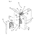
- the illustrated facade is designed as a glass facade 10 and includes a support section 20 which is provided with a screw groove 21; at least two glass elements 30a, 30b separated by a gap 31 and having an end face 33 and a side face 34; two holders 40a, 40b, by means of which the glass elements 30a, 30b are fastened to the profile 20 and which is arranged in the intermediate space 31; an insulating strip 50 disposed in the space 31 and connected to the screw groove 21, and a gasket 70 connected to the insulating strip 50 and sealing the gap 31.
- the insulating strip 50 is designed as insulating bridge 55 and outside the area of the holders 40a, 40b as insulating strip 57.
- the insulating bridge 55 has a recess 56 in which the holders 40a, 40b are received.
- the glass elements 30a, 30b consist of two disks 36, which are spaced apart by means of a spacer 32. Along the end face 33, the glass elements 30a, 30b have a channel 35, which may be continuous. In the channel 35, the holder 40a, 40b, which fasten the glass elements 30a, 30b non-positively to the support section 20.
- the insulating bridge 55 is arranged centrally along the profile 20.
- the insulating bridge 55 and the insulating web 57 form on the outside a continuous groove 62, 63, to which the seal 70 is attached.
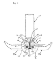
- the holders 40a, 40b are fastened by means of a screw 44 to the screw 21 of the support section 20 and hold the glass elements 30a, 30b on the support section 20 by these pressed by the holder 40a, 40b to the outside mounted sealing elements 24 become.
- the sealing elements 24 form with the carrier profile 20th inter alia, a cavity 28 in which a sealing lip 26 rests against the screw groove 21. Further sealing lips 25 of the sealing elements 24 seal the facade 10 in the region of the disk 36 of the glass element 30a, 30b.
- the sealing elements 24 on three hollow chambers 27, facilitating a squeezing of the foot allow easy attachment of the sealing elements 24 to the screw groove.
- the hollow chambers 27 contribute to the insulating properties of the facade construction.
- the seal 70 is attached to the groove 62, 63 of the insulating strip 50. Sealing lips 71 a, 71 b of the seal 70 abut against the end faces 33 of the glass elements 30 a, 30 b and seal the intermediate space 31.
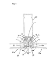
- the insulating strip 50 guide arms 58 on which two projections 59 and a pin 52 are arranged.
- the projections 59 engage in grooves 22 of the carrier profile 20, and the pin 52 penetrates into a groove 23 of the carrier profile 20 a.
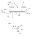
- FIG. 7 shows the Isolier Georgia 55 two cheeks 60a, 60b and a base 61 and has in the region of the holder 40a, 40b, the recess 56 in which the holders 40a, 40b are received.
- the cheeks 60a, 60b each have a groove 62 and are aligned with a groove 63 of the base 61.
- the recess 56 extends in the longitudinal direction x from the first cheek 60a to the second cheek 60b, and in the transverse direction y up to the groove 54th ,
- the Fig. 8 shows that the insulating bridge 55 has two guide arms 58, on each of which a projection 59 is arranged.
- the projections 59 are provided to secure the insulating bridge 55 to the screw groove 21 of the carrier profile 20 by being received in the grooves 22.
- the forms Fig. 8 the pin 52, which is received in the groove 23 of the screw 21 of the support section 20.
- the groove 62, 63 is arranged, which is provided for receiving a latching element 75 of the seal 70.
- the insulating bridge 55 has a Hollow chamber 51, which contributes to improved insulating properties of the facade construction.
- Fig. 9 shows that the seal 70 in the middle of the latch member 75 and the sealing lips 71 a, 71 b has.
- the sealing lips 71 a, 71 b each have a sealing lug 73.
- the sealing lugs 73 are provided to abut against the end faces 33 of the glass elements 30a, 30b and to seal the gap 31.
- the latching element 75 has a cavity 72, which is arranged centrally and facilitates the compression of the latching element 75, which thus can be easily introduced into the groove 62, 63 of the insulating strip 50.
- the locking pins 74 which are attached to the latching element 75, also strengthen the connection with the groove 62, 63 and thereby secure the seal 70 on the insulating strip 50th
- FIGS. 10, 11 and 12 show various views of the holder 40a, 40b.
- the holder 40a, 40b has a holding arm 41, which consists of a web 42 and a head 43 and the glass element 30a, 30b attached to the support profile 20 in the region of the channel 35.
- the support surface 46 and the projection 47 serve as a centering aid and facilitate the attachment of the holder 40a, 40b to the screw groove 21.
- the holder 40a, 40b has an opening 45 through which the holder 40a, 40b by means of a screw 44 at the screw groove 21 can be fixed. In this case, the head of the screw 44 is received in the recess 48, which is arranged on the side facing away from the profile 20 of the holder 40a, 40b.
- the embodiment of a glass facade 10 described above is characterized by a high thermal insulation.
- the reason for this is above all that the insulating strip 50 extends continuously through the intermediate space 31.
- the functional arrangement of the insulating strip 50 in an insulating bridge 55 and an insulating web 57 not least ensures a simple and practical installation.
Landscapes
- Engineering & Computer Science (AREA)
- Civil Engineering (AREA)
- Structural Engineering (AREA)
- Load-Bearing And Curtain Walls (AREA)
- Joining Of Glass To Other Materials (AREA)
Abstract
Description
Die Erfindung betrifft eine Fassade, insbesondere Glasfassade, die ein Trägerprofil, das mit einer Schraubnut versehen ist, und wenigstens zwei Glaselemente, die durch einen Zwischenraum voneinander getrennt sind, umfasst. Mittels eines Halters, der in dem Zwischenraum angeordnet ist, sind die Glaselemente an dem Trägerprofil befestigt. In dem Zwischenraum ist ferner eine Isolierleiste angeordnet, die mit der Schraubnut verbunden ist. Eine Dichtung, die den Zwischenraum abdichtet, ist auf der der Schraubnut abgewandten Seite der Isolierleiste mit dieser verbunden.The invention relates to a facade, in particular glass facade, which comprises a carrier profile which is provided with a screw groove, and at least two glass elements, which are separated from each other by a gap. By means of a holder which is arranged in the intermediate space, the glass elements are fastened to the carrier profile. In the intermediate space an insulating strip is further arranged, which is connected to the screw groove. A seal which seals the gap is connected to the screw groove facing away from the insulating strip with this.
In
Der Erfindung liegt die Aufgabe zugrunde, eine Fassade zu schaffen, die sich durch eine hohe Wärmedämmung auszeichnet.The invention has for its object to provide a facade that is characterized by a high thermal insulation.
Diese Aufgabe wird durch eine Fassade gemäß Anspruch 1 gelöst. Bevorzugte Ausgestaltungen der Erfindung werden in den Ansprüchen 2 bis 19 definiert.This object is achieved by a facade according to
Die erfindungsgemäße Fassade weist in dem durch zwei Glaselemente abgegrenzten Zwischenraum eine sich in einer Längsrichtung erstreckende Isolierleiste auf, welche vorzugsweise mit einer Schraubnut des Trägerprofils verbunden ist. Eine Dichtung ist mit der Isolierleiste verbunden und dichtet den Zwischenraum ab. Die Isolierleiste ist mit einer Aussparung versehen, in welche ein Halter aufgenommen ist. Dadurch erstreckt sich die Isolierleiste entlang des Zwischenraums auch im Bereich des Halters. Die durchgängig verlaufende Isolierleiste stellt eine hohe Wärmedämmung sicher.The façade according to the invention has, in the intermediate space bounded by two glass elements, an insulating strip extending in a longitudinal direction, which is preferably connected to a screw groove of the carrier profile. A seal is connected to the insulating strip and seals the gap. The insulating strip is provided with a recess into which a holder is received. As a result, the insulating strip extends along the gap in the region of the holder. The continuous insulating strip ensures high thermal insulation.
Bevorzugt setzt sich die Isolierleiste aus Isolierbrücken und Isolierstegen zusammen. Dabei ist eine Isolierbrücke mit der Aussparung versehen und im Bereich des Halters in dem Zwischenraum angeordnet. Der Isoliersteg ist außerhalb des Bereichs des Halters in dem Zwischenraum angeordnet. Dies hat den Vorteil, dass zur Befestigung eines Glaselements die Anzahl und Position der Halter variabel gestaltet werden kann und dabei eine hohe Qualität der Wärmedämmung erzielt wird.Preferably, the insulating strip is composed of insulating bridges and insulating bars together. In this case, an insulating bridge is provided with the recess and arranged in the region of the holder in the intermediate space. The insulating bar is located outside the area of the holder in the gap. This has the advantage that for the attachment of a glass element, the number and position of the holder can be made variable while a high quality of thermal insulation is achieved.
Gemäß einer bevorzugten Ausführungsform weist die Isolierbrücke eine erste Wange und eine zweite Wange auf, die in Längsrichtung durch die Aussparung voneinander beabstandet sind. Weiterhin umfasst die Isolierbrücke eine Basis, welche die erste Wange und die zweite Wange miteinander verbindet. Bevorzugt erstreckt sich die Aussparung in einer zu der Längsrichtung orthogonalen Querrichtung bis zur Basis. Dabei ist die Aussparung derart ausgestaltet, dass sie zur Aufnahme eines oder mehrerer am Trägerprofil befestigten Halter geeignet ist.According to a preferred embodiment, the insulating bridge on a first cheek and a second cheek, which are spaced apart in the longitudinal direction by the recess. Furthermore, the insulating bridge comprises a base connecting the first cheek and the second cheek. Preferably, the recess extends in a direction orthogonal to the longitudinal direction transverse to the base. In this case, the recess is designed such that it is suitable for receiving one or more holders attached to the carrier profile.
In einer weiteren bevorzugten Ausgestaltung ist die Basis mit einer Nut versehen, welche zur Aufnahme der Dichtung dient. Die Nut gewährleistet eine einfache Montage der Dichtung.In a further preferred embodiment, the base is provided with a groove which serves to receive the seal. The groove ensures easy installation of the seal.
Zweckmäßig sind die Wangen ebenfalls mit einer Nut versehen, die mit der Nut der Basis fluchtet und an der die Dichtung befestigt ist. Durch diese Ausgestaltung ist das sichere Anbringen der Dichtung längs der Isolierbrücke möglich. Gemäß einer weiteren bevorzugten Ausführungsform sind die Wangen jeweils mit einer Hohlkammer versehen, wodurch die isolierenden Eigenschaften der Isolierbrücke weiter verbessert werden.Suitably, the cheeks are also provided with a groove which is aligned with the groove of the base and to which the seal is attached. By this configuration, the secure attachment of the seal along the insulating bridge is possible. According to a further preferred embodiment, the cheeks are each provided with a hollow chamber, whereby the insulating properties of the insulating bridge are further improved.
In einer weiteren bevorzugten Ausgestaltung ist die Isolierbrücke in der Schraubnut formschlüssig aufgenommen. Dabei kann die Isolierbrücke auf der dem Trägerprofil zugewandten Seite einen Zapfen aufweisen, der in die Schraubnut des Trägerprofils kraftschlüssig und/oder formschlüssig eingreift. Bevorzugt kann die Isolierbrücke wenigstens einen Führungsarm aufweisen, der außen an der Schraubnut anliegt. Dabei weist die Schraubnut vorzugsweise wenigstens eine Rille auf, und der Führungsarm ist mit einem Vorsprung versehen, der kraftschlüssig und/oder formschlüssig in die Rille eingreift. In diesen möglichen Ausgestaltungen erleichtert der Zapfen das richtige Ausrichten einer Isolierbrücke an der Schraubnut des Trägerprofils, und ein einfaches und sicheres Anbringen der Isolierbrücke wird ermöglicht.In a further preferred embodiment, the insulating bridge is received positively in the screw groove. In this case, the insulating bridge on the carrier profile side facing a pin which engages positively and / or positively in the screw groove of the carrier profile. Preferably, the insulating bridge may have at least one guide arm, which bears against the outside of the screw groove. In this case, the Schraubnut preferably has at least one groove, and the guide arm is provided with a projection which engages positively and / or positively in the groove. In these possible embodiments, the pin facilitates the proper alignment of an insulating bridge on the screw groove of the carrier profile, and a simple and secure attachment of the insulating bridge is made possible.
Gemäß einer weiteren bevorzugten Ausführungsform grenzt der Isoliersteg in Längsrichtung an den Wangen an. Bevorzugt können der Isoliersteg und die Wangen den gleichen Querschnitt aufweisen. Dadurch ist analog zur Isolierbrücke ebenfalls ein einfaches und sicheres Anbringen des Isolierstegs möglich. Außerdem weist der Isoliersteg dadurch ähnliche isolierende Eigenschaften wie die Isolierbrücke auf. Damit ist ebenfalls gewährleistet, dass die außenseitig angebrachte Nut eines an einer Isolierbrücke angrenzenden Isolierstegs in die Nut der Isolierbrücke fluchtet.According to a further preferred embodiment, the insulating web adjoins the cheeks in the longitudinal direction. Preferably, the insulating web and the cheeks may have the same cross-section. This is analogous to the insulating bridge also a simple and safe attachment of the insulating bar possible. In addition, the insulating bar thereby has similar insulating properties as the insulating bridge. This also ensures that the groove attached to the outside of an insulating web adjacent to an insulating bridge is aligned in the groove of the insulating bridge.
In einer weiteren bevorzugten Ausgestaltung weist die außenseitig angebrachte Dichtung ein Einrastelement auf, das in die Nut der Isolierleiste eingreift, wobei vorzugsweise das Einrastelement einen Hohlraum und wenigstens einen Rastzapfen umfasst. Zweckmäßig kann die Dichtung wenigstens eine Dichtlippe aufweisen, die vorzugsweise mit einer Dichtfahne versehen ist. Die Dichtfahne liegt an einer Stirnfläche des Glaselements an. Der Hohlraum ist im Bereich des Einrastelements angeordnet und ermöglicht ein leichtes Anbringen der Dichtung an der Isolierleiste, indem sie die Nachgiebigkeit des Einrastelements erhöht, welches somit einfach in der Nut angebracht werden kann. Das Einrastelement weist wenigstens einen Rastzapfen auf, welcher in der Nut der Isolierleiste aufgenommen wird und somit das Herausziehen der Dichtung erschwert.In a further preferred embodiment, the externally mounted seal on a latching element which engages in the groove of the insulating strip, wherein preferably the latching element comprises a cavity and at least one locking pin. Suitably, the seal may have at least one sealing lip, which is preferably provided with a sealing lug. The sealing lug bears against an end face of the glass element. The cavity is located in the region of the latching element and allows for easy attachment of the gasket to the insulating strip by increasing the compliance of the latching element, which thus can be easily mounted in the groove. The latching element has at least one latching pin, which is received in the groove of the insulating strip and thus complicates the extraction of the seal.
In einer weiteren bevorzugten Ausgestaltung weist der Halter zur Befestigung der Glaselemente einen Haltearm auf, der vorzugsweise aus einem dünnen Steg und einem verdickten Kopf gebildet ist. Weiterhin können die Glaselemente jeweils eine Stirnfläche und eine Seitenfläche aufweisen, wobei im Bereich der Stirnfläche ein Kanal vorgesehen ist, in welchen der Haltearm eingreift. Durch diese Ausgestaltung der Halter wird an dem Haltearm eine linienförmige Anlagefläche geschaffen, welche entlang des Kanals der Isolierglasscheibe diese an dem Trägerprofil festhält. Diese Ausgestaltung hat den Vorteil, dass ein gewisser Toleranzausgleich stattfinden kann, beispielsweise wenn das Glaselement in Folge von Druck oder Wärmebelastung sich etwas verschwenkt oder bewegt.In a further preferred embodiment, the holder for fixing the glass elements on a holding arm, which is preferably formed of a thin web and a thickened head. Furthermore, the glass elements may each have an end face and a side face, wherein in the region of the end face a channel is provided, in which the holding arm engages. By this embodiment of the holder, a linear contact surface is created on the support arm, which holds along the channel of the insulating glass this to the support profile. This embodiment has the advantage that a certain tolerance compensation can take place, for example when the glass element pivots or moves slightly as a result of pressure or heat load.
Von Vorteil ist es, den Halter mit einer Öffnung zu versehen, die geeignet ist, eine Schraube zur Befestigung des Halters an der Schraubnut aufzunehmen. Bevorzugt kann der Halter eine Vertiefung aufweisen, die geeignet ist, einen Kopf der Schraube aufzunehmen. Durch die durchgängige Ausgestaltung der Schraubnut kann der Halter variabel in Längsrichtung des Trägerprofils angeordnet werden, da die Schrauben sich an einer beliebigen Stelle der Schraubnut eindrehen lassen.It is advantageous to provide the holder with an opening which is adapted to receive a screw for fastening the holder to the screw groove. Preferably, the holder may have a recess adapted to receive a head of the screw. Due to the continuous configuration of the screw groove, the holder can be arranged variably in the longitudinal direction of the carrier profile, since the screws can be screwed in at any point of the screw groove.
Zweckmäßig weist der Halter eine Auflagefläche auf, die auf der Schraubnut aufsitzt, wobei vorzugsweise die Auflagefläche mit wenigstens einem Vorsprung versehen ist, der die Schraubnut außen umgreift. Dabei dienen die Auflagefläche und der Vorsprung als Zentrierhilfe, womit eine einfache Befestigung des Halters an der Schraubnut gewährleistet ist.Suitably, the holder has a bearing surface which rests on the screw groove, wherein preferably the bearing surface is provided with at least one projection which engages around the screw groove on the outside. The bearing surface and the projection serve as centering, whereby a simple attachment of the holder is ensured at the Schraubnut.
Einzelheiten und weitere Vorteile der Erfindung ergeben sich aus der nachfolgenden Beschreibung eines bevorzugten Ausführungsbeispieles. In den das Ausführungsbeispiel lediglich schematisch darstellenden Zeichnungen veranschaulichen im Einzelnen:
- Fig. 1
- eine Explosionsdarstellung der erfindungsgemäßen Fassade;
- Fig. 2
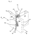
- eine perspektivische Ansicht der erfindungsgemäßen Fassade;
- Fig. 3
- einen Schnitt gemäß der Linie III-III in
Fig. 1 ; - Fig. 4
- einen Schnitt gemäß der Linie IV-IV in
Fig. 2 ; - Fig. 5
- eine vergrößerte Darstellung des in
Fig. 3 mit V gekennzeichne- ten Bereichs; - Fig. 6
- eine vergrößerte Darstellung des in
Fig. 4 mit VI gekennzeich- neten Bereichs; - Fig. 7
- eine Seitenansicht einer Isolierbrücke;
- Fig. 8
- einen Schnitt gemäß der Linie VIII-VIII in
Fig. 7 ; - Fig. 9
- eine Seitenansicht einer Dichtung;
- Fig. 10
- eine Draufsicht auf einen Halter;
- Fig. 11
- eine Seitenansicht des Halters gemäß
Fig. 10 und - Fig. 12
- eine weitere Seitenansicht des Halters gemäß
Fig. 10 .
- Fig. 1
- an exploded view of the facade of the invention;
- Fig. 2
- a perspective view of the facade of the invention;
- Fig. 3
- a section along the line III-III in
Fig. 1 ; - Fig. 4
- a section along the line IV-IV in
Fig. 2 ; - Fig. 5
- an enlarged view of the in
Fig. 3 area marked V; - Fig. 6
- an enlarged view of the in
Fig. 4 VI marked area; - Fig. 7
- a side view of an insulating bridge;
- Fig. 8
- a section along the line VIII-VIII in
Fig. 7 ; - Fig. 9
- a side view of a seal;
- Fig. 10
- a plan view of a holder;
- Fig. 11
- a side view of the holder according to
Fig. 10 and - Fig. 12
- another side view of the holder according to
Fig. 10 ,
Die in
Die Glaselemente 30a, 30b bestehen aus zwei Scheiben 36, welche mit Hilfe eines Abstandhalters 32 beabstandet sind. Entlang der Stirnfläche 33 weisen die Glaselemente 30a, 30b einen Kanal 35 auf, welcher durchgängig ausgebildet sein kann. In den Kanal 35 greifen die Halter 40a, 40b ein, welche die Glaselemente 30a, 30b kraftschlüssig an dem Trägerprofil 20 befestigen.The
Im Bereich der Halter 40a, 40b ist die Isolierbrücke 55 mittig entlang des Profils 20 angeordnet. Die Isolierbrücke 55 und der Isoliersteg 57 formen außenseitig eine durchgehende Nut 62, 63, an welcher die Dichtung 70 befestigt wird.In the area of the
Wie die
Wie die
Wie
Die
Die
Die zuvor beschriebene Ausführungsform einer Glasfassade 10 zeichnet sich durch eine hohe Wärmedämmung aus. Grund hierfür ist vor allem, dass sich die Isolierleiste 50 durchgängig durch den Zwischenraum 31 erstreckt. Die funktionelle Gliederung der Isolierleiste 50 in eine Isolierbrücke 55 und einen Isoliersteg 57 stellt nicht zuletzt eine einfache und praxisgerechte Montage sicher.The embodiment of a
- 1010
- Glasfassadeglass facade
- 2020
- Trägerprofilcarrier profile
- 2121
- Schraubnutscrew groove
- 2222
- Rillegroove
- 2323
- Nutgroove
- 2424
- Dichtelementsealing element
- 2525
- Dichtlippensealing lips
- 2626
- Dichtlippesealing lip
- 2727
- Hohlkammerhollow
- 2828
- Hohlraumcavity
- 30a30a
- Glaselementglass element
- 30b30b
- Glaselementglass element
- 3131
- Zwischenraumgap
- 3232
- Abstandhalterspacer
- 3333
- Stirnflächeface
- 3434
- Seitenflächeside surface
- 3535
- Kanalchannel
- 3636
- Scheibedisc
- 40a40a
- Halterholder
- 40b40b
- Halterholder
- 4141
- Haltearmholding arm
- 4242
- Stegweb
- 4343
- Kopfhead
- 4444
- Schraubescrew
- 4545
- Öffnungopening
- 4646
- Auflageflächebearing surface
- 4747
- Vorsprunghead Start
- 4848
- Vertiefungdeepening
- 5050
- Isolierleisteinsulating strip
- 5151
- Hohlkammerhollow
- 5252
- Zapfenspigot
- 5353
- Vorsprunghead Start
- 5454
- Nutgroove
- 5555
- Isolierbrückeinsulating bridge
- 5656
- Aussparungrecess
- 5757
- IsolierstegInsulating web
- 5858
- Führungsarmguide
- 5959
- Vorsprunghead Start
- 60a60a
- Wangecheek
- 60b60b
- Wangecheek
- 6161
- BasisBase
- 6262
- Nutgroove
- 6363
- Nutgroove
- 7070
- Dichtungpoetry
- 71 a71 a
- Dichtlippesealing lip
- 71 b71 b
- Dichtlippesealing lip
- 7272
- Hohlraumcavity
- 7373
- Dichtfahnesealing flag
- 7474
- Rastzapfenlatching pin
- 7575
- Einrastelementlatching
- xx
- Längsrichtunglongitudinal direction
- yy
- Querrichtungtransversely
Claims (19)
Applications Claiming Priority (1)
| Application Number | Priority Date | Filing Date | Title |
|---|---|---|---|
| DE102009020078 | 2009-05-06 |
Publications (4)
| Publication Number | Publication Date |
|---|---|
| EP2248984A2 true EP2248984A2 (en) | 2010-11-10 |
| EP2248984A3 EP2248984A3 (en) | 2010-12-01 |
| EP2248984B1 EP2248984B1 (en) | 2011-08-31 |
| EP2248984B2 EP2248984B2 (en) | 2018-05-23 |
Family
ID=42312942
Family Applications (1)
| Application Number | Title | Priority Date | Filing Date |
|---|---|---|---|
| EP09172363.5A Active EP2248984B2 (en) | 2009-05-06 | 2009-10-06 | Facade, in particular glass facade |
Country Status (2)
| Country | Link |
|---|---|
| EP (1) | EP2248984B2 (en) |
| AT (1) | ATE522695T1 (en) |
Cited By (2)
| Publication number | Priority date | Publication date | Assignee | Title |
|---|---|---|---|---|
| EP2444579A1 (en) * | 2010-10-20 | 2012-04-25 | Cuhadaroglu Metal Sanayi Ve Pazarlama Anonim Sirketi | Curtain wall system wherein a special connection system is used for plate materials such as glass, aluminium sheet, etc. |
| CN106836525A (en) * | 2016-12-21 | 2017-06-13 | 无为县佳明铝塑材料有限公司 | A kind of bridge cut-off column section |
Families Citing this family (1)
| Publication number | Priority date | Publication date | Assignee | Title |
|---|---|---|---|---|
| US10309150B2 (en) * | 2017-09-14 | 2019-06-04 | Arconic Inc. | Structural glazing weather seal with captured glazing option |
Citations (1)
| Publication number | Priority date | Publication date | Assignee | Title |
|---|---|---|---|---|
| WO2004063517A2 (en) | 2003-01-08 | 2004-07-29 | SCHÜCO International KG | Façade and/or transparent roof construction and associated tool for assembling the surface elements |
Family Cites Families (4)
| Publication number | Priority date | Publication date | Assignee | Title |
|---|---|---|---|---|
| DE20300134U1 (en) † | 2003-01-08 | 2003-03-20 | Schüco International KG, 33609 Bielefeld | Support construction for double glazed facades or sky lights, has glass holder screwed onto profile via its flat underside |
| DE10319278B4 (en) * | 2003-04-29 | 2007-03-29 | Wicona Bausysteme Gmbh | Facade element for dressing a building wall |
| FR2922915A1 (en) * | 2007-10-26 | 2009-05-01 | Norsk Hydro As | SYSTEM FOR MAINTAINING A PANEL OF FRAGILE MATERIAL OF THE GLASS TYPE, ON A RIGID FRAMEWORK ON THE FACADE OF A CONSTRUCTION |
| FR2928170A1 (en) † | 2008-02-29 | 2009-09-04 | Peugeot Citroen Automobiles Sa | SEAL FOR LOCKING AN OPENER, ESPECIALLY OF DOOR OR WINDOW TYPE |
-
2009
- 2009-10-06 AT AT09172363T patent/ATE522695T1/en active
- 2009-10-06 EP EP09172363.5A patent/EP2248984B2/en active Active
Patent Citations (1)
| Publication number | Priority date | Publication date | Assignee | Title |
|---|---|---|---|---|
| WO2004063517A2 (en) | 2003-01-08 | 2004-07-29 | SCHÜCO International KG | Façade and/or transparent roof construction and associated tool for assembling the surface elements |
Cited By (2)
| Publication number | Priority date | Publication date | Assignee | Title |
|---|---|---|---|---|
| EP2444579A1 (en) * | 2010-10-20 | 2012-04-25 | Cuhadaroglu Metal Sanayi Ve Pazarlama Anonim Sirketi | Curtain wall system wherein a special connection system is used for plate materials such as glass, aluminium sheet, etc. |
| CN106836525A (en) * | 2016-12-21 | 2017-06-13 | 无为县佳明铝塑材料有限公司 | A kind of bridge cut-off column section |
Also Published As
| Publication number | Publication date |
|---|---|
| EP2248984A3 (en) | 2010-12-01 |
| EP2248984B2 (en) | 2018-05-23 |
| EP2248984B1 (en) | 2011-08-31 |
| ATE522695T1 (en) | 2011-09-15 |
Similar Documents
| Publication | Publication Date | Title |
|---|---|---|
| EP1580343B1 (en) | Element for the butt joining of profiles | |
| DE102019101451A1 (en) | Profile arrangement | |
| EP2248984B1 (en) | Facade, in particular glass facade | |
| DE102009027324B4 (en) | Power transmission device for a door system | |
| DE29718854U1 (en) | Profile frame, in particular U-profile frame for holding surface elements such as glass panes, plastic plates or the like. | |
| EP4013656B1 (en) | Integral fastening for a thermal insulation layer in a rail vehicle | |
| EP0122335B1 (en) | Profiled track | |
| EP1522670B1 (en) | Corner connector for hollow double glazing frame section members | |
| EP2101029B1 (en) | Connector | |
| DE102007053013B4 (en) | roof construction | |
| DE102020106889A1 (en) | Sealing piece for sealing a T-connection between a mullion and transom profile and a mullion-transom construction with such a sealing piece | |
| EP1830029A2 (en) | Louvre construction for façades | |
| EP2214936B1 (en) | Wiper blade | |
| DE102022205375B4 (en) | Slide rail for a door drive | |
| EP1186723A2 (en) | Mounting device for a mullion and transom facade | |
| DE102010060672A1 (en) | Window or door frame | |
| DE20100751U1 (en) | Clamp holder for plate-shaped components | |
| DE20015489U1 (en) | Glazed seam insert | |
| DE19917036C2 (en) | Sprossenfenster | |
| DE102004043964A1 (en) | connecting device | |
| DE202010013228U1 (en) | Support arrangement for a window, a door or the like. | |
| DE102006005235B4 (en) | Slat arrangement for facades | |
| DE9217883U1 (en) | Block part for fixing glass panes or the like. in grooves of door or window frames | |
| DE102015100525A1 (en) | Method for assembling a mullion-transom construction and mullion-transom construction | |
| DE7230142U (en) | Arrangement for electronic slide-in systems |
Legal Events
| Date | Code | Title | Description |
|---|---|---|---|
| PUAI | Public reference made under article 153(3) epc to a published international application that has entered the european phase |
Free format text: ORIGINAL CODE: 0009012 |
|
| PUAL | Search report despatched |
Free format text: ORIGINAL CODE: 0009013 |
|
| AK | Designated contracting states |
Kind code of ref document: A2 Designated state(s): AT BE BG CH CY CZ DE DK EE ES FI FR GB GR HR HU IE IS IT LI LT LU LV MC MK MT NL NO PL PT RO SE SI SK SM TR |
|
| AK | Designated contracting states |
Kind code of ref document: A3 Designated state(s): AT BE BG CH CY CZ DE DK EE ES FI FR GB GR HR HU IE IS IT LI LT LU LV MC MK MT NL NO PL PT RO SE SI SK SM TR |
|
| 17P | Request for examination filed |
Effective date: 20101111 |
|
| GRAP | Despatch of communication of intention to grant a patent |
Free format text: ORIGINAL CODE: EPIDOSNIGR1 |
|
| RIC1 | Information provided on ipc code assigned before grant |
Ipc: E04B 2/88 20060101ALI20110420BHEP Ipc: E06B 3/54 20060101AFI20110420BHEP |
|
| GRAS | Grant fee paid |
Free format text: ORIGINAL CODE: EPIDOSNIGR3 |
|
| GRAA | (expected) grant |
Free format text: ORIGINAL CODE: 0009210 |
|
| AK | Designated contracting states |
Kind code of ref document: B1 Designated state(s): AT BE BG CH CY CZ DE DK EE ES FI FR GB GR HR HU IE IS IT LI LT LU LV MC MK MT NL NO PL PT RO SE SI SK SM TR |
|
| REG | Reference to a national code |
Ref country code: CH Ref legal event code: EP Ref country code: GB Ref legal event code: FG4D Free format text: NOT ENGLISH |
|
| REG | Reference to a national code |
Ref country code: IE Ref legal event code: FG4D Free format text: LANGUAGE OF EP DOCUMENT: GERMAN |
|
| REG | Reference to a national code |
Ref country code: CH Ref legal event code: NV Representative=s name: BOHEST AG |
|
| REG | Reference to a national code |
Ref country code: DE Ref legal event code: R096 Ref document number: 502009001241 Country of ref document: DE Effective date: 20111027 |
|
| REG | Reference to a national code |
Ref country code: NL Ref legal event code: VDEP Effective date: 20110831 |
|
| LTIE | Lt: invalidation of european patent or patent extension |
Effective date: 20110831 |
|
| PG25 | Lapsed in a contracting state [announced via postgrant information from national office to epo] |
Ref country code: NL Free format text: LAPSE BECAUSE OF FAILURE TO SUBMIT A TRANSLATION OF THE DESCRIPTION OR TO PAY THE FEE WITHIN THE PRESCRIBED TIME-LIMIT Effective date: 20110831 Ref country code: NO Free format text: LAPSE BECAUSE OF FAILURE TO SUBMIT A TRANSLATION OF THE DESCRIPTION OR TO PAY THE FEE WITHIN THE PRESCRIBED TIME-LIMIT Effective date: 20111130 Ref country code: LT Free format text: LAPSE BECAUSE OF FAILURE TO SUBMIT A TRANSLATION OF THE DESCRIPTION OR TO PAY THE FEE WITHIN THE PRESCRIBED TIME-LIMIT Effective date: 20110831 Ref country code: SE Free format text: LAPSE BECAUSE OF FAILURE TO SUBMIT A TRANSLATION OF THE DESCRIPTION OR TO PAY THE FEE WITHIN THE PRESCRIBED TIME-LIMIT Effective date: 20110831 Ref country code: IS Free format text: LAPSE BECAUSE OF FAILURE TO SUBMIT A TRANSLATION OF THE DESCRIPTION OR TO PAY THE FEE WITHIN THE PRESCRIBED TIME-LIMIT Effective date: 20111231 Ref country code: FI Free format text: LAPSE BECAUSE OF FAILURE TO SUBMIT A TRANSLATION OF THE DESCRIPTION OR TO PAY THE FEE WITHIN THE PRESCRIBED TIME-LIMIT Effective date: 20110831 Ref country code: HR Free format text: LAPSE BECAUSE OF FAILURE TO SUBMIT A TRANSLATION OF THE DESCRIPTION OR TO PAY THE FEE WITHIN THE PRESCRIBED TIME-LIMIT Effective date: 20110831 |
|
| PG25 | Lapsed in a contracting state [announced via postgrant information from national office to epo] |
Ref country code: GR Free format text: LAPSE BECAUSE OF FAILURE TO SUBMIT A TRANSLATION OF THE DESCRIPTION OR TO PAY THE FEE WITHIN THE PRESCRIBED TIME-LIMIT Effective date: 20111201 Ref country code: CY Free format text: LAPSE BECAUSE OF FAILURE TO SUBMIT A TRANSLATION OF THE DESCRIPTION OR TO PAY THE FEE WITHIN THE PRESCRIBED TIME-LIMIT Effective date: 20110831 Ref country code: LV Free format text: LAPSE BECAUSE OF FAILURE TO SUBMIT A TRANSLATION OF THE DESCRIPTION OR TO PAY THE FEE WITHIN THE PRESCRIBED TIME-LIMIT Effective date: 20110831 Ref country code: SI Free format text: LAPSE BECAUSE OF FAILURE TO SUBMIT A TRANSLATION OF THE DESCRIPTION OR TO PAY THE FEE WITHIN THE PRESCRIBED TIME-LIMIT Effective date: 20110831 |
|
| REG | Reference to a national code |
Ref country code: IE Ref legal event code: FD4D |
|
| PG25 | Lapsed in a contracting state [announced via postgrant information from national office to epo] |
Ref country code: SK Free format text: LAPSE BECAUSE OF FAILURE TO SUBMIT A TRANSLATION OF THE DESCRIPTION OR TO PAY THE FEE WITHIN THE PRESCRIBED TIME-LIMIT Effective date: 20110831 Ref country code: IE Free format text: LAPSE BECAUSE OF FAILURE TO SUBMIT A TRANSLATION OF THE DESCRIPTION OR TO PAY THE FEE WITHIN THE PRESCRIBED TIME-LIMIT Effective date: 20110831 Ref country code: CZ Free format text: LAPSE BECAUSE OF FAILURE TO SUBMIT A TRANSLATION OF THE DESCRIPTION OR TO PAY THE FEE WITHIN THE PRESCRIBED TIME-LIMIT Effective date: 20110831 |
|
| PG25 | Lapsed in a contracting state [announced via postgrant information from national office to epo] |
Ref country code: EE Free format text: LAPSE BECAUSE OF FAILURE TO SUBMIT A TRANSLATION OF THE DESCRIPTION OR TO PAY THE FEE WITHIN THE PRESCRIBED TIME-LIMIT Effective date: 20110831 Ref country code: RO Free format text: LAPSE BECAUSE OF FAILURE TO SUBMIT A TRANSLATION OF THE DESCRIPTION OR TO PAY THE FEE WITHIN THE PRESCRIBED TIME-LIMIT Effective date: 20110831 Ref country code: PL Free format text: LAPSE BECAUSE OF FAILURE TO SUBMIT A TRANSLATION OF THE DESCRIPTION OR TO PAY THE FEE WITHIN THE PRESCRIBED TIME-LIMIT Effective date: 20110831 Ref country code: IT Free format text: LAPSE BECAUSE OF FAILURE TO SUBMIT A TRANSLATION OF THE DESCRIPTION OR TO PAY THE FEE WITHIN THE PRESCRIBED TIME-LIMIT Effective date: 20110831 Ref country code: PT Free format text: LAPSE BECAUSE OF FAILURE TO SUBMIT A TRANSLATION OF THE DESCRIPTION OR TO PAY THE FEE WITHIN THE PRESCRIBED TIME-LIMIT Effective date: 20120102 Ref country code: MC Free format text: LAPSE BECAUSE OF NON-PAYMENT OF DUE FEES Effective date: 20111031 |
|
| PLBI | Opposition filed |
Free format text: ORIGINAL CODE: 0009260 |
|
| PG25 | Lapsed in a contracting state [announced via postgrant information from national office to epo] |
Ref country code: DK Free format text: LAPSE BECAUSE OF FAILURE TO SUBMIT A TRANSLATION OF THE DESCRIPTION OR TO PAY THE FEE WITHIN THE PRESCRIBED TIME-LIMIT Effective date: 20110831 |
|
| PLAX | Notice of opposition and request to file observation + time limit sent |
Free format text: ORIGINAL CODE: EPIDOSNOBS2 |
|
| 26 | Opposition filed |
Opponent name: SCHUECO INTERNATIONAL KG Effective date: 20120531 |
|
| REG | Reference to a national code |
Ref country code: DE Ref legal event code: R026 Ref document number: 502009001241 Country of ref document: DE Effective date: 20120531 |
|
| PLBB | Reply of patent proprietor to notice(s) of opposition received |
Free format text: ORIGINAL CODE: EPIDOSNOBS3 |
|
| PG25 | Lapsed in a contracting state [announced via postgrant information from national office to epo] |
Ref country code: MK Free format text: LAPSE BECAUSE OF FAILURE TO SUBMIT A TRANSLATION OF THE DESCRIPTION OR TO PAY THE FEE WITHIN THE PRESCRIBED TIME-LIMIT Effective date: 20110831 Ref country code: MT Free format text: LAPSE BECAUSE OF FAILURE TO SUBMIT A TRANSLATION OF THE DESCRIPTION OR TO PAY THE FEE WITHIN THE PRESCRIBED TIME-LIMIT Effective date: 20110831 |
|
| PG25 | Lapsed in a contracting state [announced via postgrant information from national office to epo] |
Ref country code: ES Free format text: LAPSE BECAUSE OF FAILURE TO SUBMIT A TRANSLATION OF THE DESCRIPTION OR TO PAY THE FEE WITHIN THE PRESCRIBED TIME-LIMIT Effective date: 20111211 Ref country code: SM Free format text: LAPSE BECAUSE OF FAILURE TO SUBMIT A TRANSLATION OF THE DESCRIPTION OR TO PAY THE FEE WITHIN THE PRESCRIBED TIME-LIMIT Effective date: 20110831 |
|
| PG25 | Lapsed in a contracting state [announced via postgrant information from national office to epo] |
Ref country code: LU Free format text: LAPSE BECAUSE OF NON-PAYMENT OF DUE FEES Effective date: 20111006 |
|
| PG25 | Lapsed in a contracting state [announced via postgrant information from national office to epo] |
Ref country code: BG Free format text: LAPSE BECAUSE OF FAILURE TO SUBMIT A TRANSLATION OF THE DESCRIPTION OR TO PAY THE FEE WITHIN THE PRESCRIBED TIME-LIMIT Effective date: 20111130 |
|
| PG25 | Lapsed in a contracting state [announced via postgrant information from national office to epo] |
Ref country code: TR Free format text: LAPSE BECAUSE OF FAILURE TO SUBMIT A TRANSLATION OF THE DESCRIPTION OR TO PAY THE FEE WITHIN THE PRESCRIBED TIME-LIMIT Effective date: 20110831 |
|
| PG25 | Lapsed in a contracting state [announced via postgrant information from national office to epo] |
Ref country code: HU Free format text: LAPSE BECAUSE OF FAILURE TO SUBMIT A TRANSLATION OF THE DESCRIPTION OR TO PAY THE FEE WITHIN THE PRESCRIBED TIME-LIMIT Effective date: 20110831 |
|
| APAH | Appeal reference modified |
Free format text: ORIGINAL CODE: EPIDOSCREFNO |
|
| APBM | Appeal reference recorded |
Free format text: ORIGINAL CODE: EPIDOSNREFNO |
|
| APBP | Date of receipt of notice of appeal recorded |
Free format text: ORIGINAL CODE: EPIDOSNNOA2O |
|
| APBQ | Date of receipt of statement of grounds of appeal recorded |
Free format text: ORIGINAL CODE: EPIDOSNNOA3O |
|
| REG | Reference to a national code |
Ref country code: CH Ref legal event code: PCAR Free format text: NEW ADDRESS: HOLBEINSTRASSE 36-38, 4051 BASEL (CH) |
|
| REG | Reference to a national code |
Ref country code: FR Ref legal event code: PLFP Year of fee payment: 7 |
|
| REG | Reference to a national code |
Ref country code: FR Ref legal event code: PLFP Year of fee payment: 8 |
|
| PGFP | Annual fee paid to national office [announced via postgrant information from national office to epo] |
Ref country code: FR Payment date: 20161025 Year of fee payment: 8 |
|
| APBU | Appeal procedure closed |
Free format text: ORIGINAL CODE: EPIDOSNNOA9O |
|
| PUAH | Patent maintained in amended form |
Free format text: ORIGINAL CODE: 0009272 |
|
| STAA | Information on the status of an ep patent application or granted ep patent |
Free format text: STATUS: PATENT MAINTAINED AS AMENDED |
|
| 27A | Patent maintained in amended form |
Effective date: 20180523 |
|
| AK | Designated contracting states |
Kind code of ref document: B2 Designated state(s): AT BE BG CH CY CZ DE DK EE ES FI FR GB GR HR HU IE IS IT LI LT LU LV MC MK MT NL NO PL PT RO SE SI SK SM TR |
|
| REG | Reference to a national code |
Ref country code: DE Ref legal event code: R102 Ref document number: 502009001241 Country of ref document: DE |
|
| REG | Reference to a national code |
Ref country code: CH Ref legal event code: AELC |
|
| REG | Reference to a national code |
Ref country code: FR Ref legal event code: ST Effective date: 20180629 |
|
| PG25 | Lapsed in a contracting state [announced via postgrant information from national office to epo] |
Ref country code: FR Free format text: LAPSE BECAUSE OF NON-PAYMENT OF DUE FEES Effective date: 20171031 |
|
| PGFP | Annual fee paid to national office [announced via postgrant information from national office to epo] |
Ref country code: GB Payment date: 20201022 Year of fee payment: 12 |
|
| PGFP | Annual fee paid to national office [announced via postgrant information from national office to epo] |
Ref country code: BE Payment date: 20211021 Year of fee payment: 13 |
|
| GBPC | Gb: european patent ceased through non-payment of renewal fee |
Effective date: 20211006 |
|
| PG25 | Lapsed in a contracting state [announced via postgrant information from national office to epo] |
Ref country code: GB Free format text: LAPSE BECAUSE OF NON-PAYMENT OF DUE FEES Effective date: 20211006 |
|
| PGFP | Annual fee paid to national office [announced via postgrant information from national office to epo] |
Ref country code: DE Payment date: 20221101 Year of fee payment: 14 Ref country code: AT Payment date: 20221018 Year of fee payment: 14 |
|
| PGFP | Annual fee paid to national office [announced via postgrant information from national office to epo] |
Ref country code: CH Payment date: 20221027 Year of fee payment: 14 |
|
| REG | Reference to a national code |
Ref country code: BE Ref legal event code: MM Effective date: 20221031 |
|
| PG25 | Lapsed in a contracting state [announced via postgrant information from national office to epo] |
Ref country code: BE Free format text: LAPSE BECAUSE OF NON-PAYMENT OF DUE FEES Effective date: 20221031 |
|
| REG | Reference to a national code |
Ref country code: DE Ref legal event code: R119 Ref document number: 502009001241 Country of ref document: DE |
|
| REG | Reference to a national code |
Ref country code: CH Ref legal event code: PL |
|
| REG | Reference to a national code |
Ref country code: AT Ref legal event code: MM01 Ref document number: 522695 Country of ref document: AT Kind code of ref document: T Effective date: 20231006 |
|
| PG25 | Lapsed in a contracting state [announced via postgrant information from national office to epo] |
Ref country code: CH Free format text: LAPSE BECAUSE OF NON-PAYMENT OF DUE FEES Effective date: 20231031 |
|
| PG25 | Lapsed in a contracting state [announced via postgrant information from national office to epo] |
Ref country code: AT Free format text: LAPSE BECAUSE OF NON-PAYMENT OF DUE FEES Effective date: 20231006 |
|
| PG25 | Lapsed in a contracting state [announced via postgrant information from national office to epo] |
Ref country code: DE Free format text: LAPSE BECAUSE OF NON-PAYMENT OF DUE FEES Effective date: 20240501 Ref country code: CH Free format text: LAPSE BECAUSE OF NON-PAYMENT OF DUE FEES Effective date: 20231031 Ref country code: AT Free format text: LAPSE BECAUSE OF NON-PAYMENT OF DUE FEES Effective date: 20231006 |