EP2248714B1 - Quick Release Device for Bicycle - Google Patents
Quick Release Device for Bicycle Download PDFInfo
- Publication number
- EP2248714B1 EP2248714B1 EP09157734A EP09157734A EP2248714B1 EP 2248714 B1 EP2248714 B1 EP 2248714B1 EP 09157734 A EP09157734 A EP 09157734A EP 09157734 A EP09157734 A EP 09157734A EP 2248714 B1 EP2248714 B1 EP 2248714B1
- Authority
- EP
- European Patent Office
- Prior art keywords
- lever arm
- quick release
- release device
- cam
- ears
- Prior art date
- Legal status (The legal status is an assumption and is not a legal conclusion. Google has not performed a legal analysis and makes no representation as to the accuracy of the status listed.)
- Not-in-force
Links
- 210000005069 ears Anatomy 0.000 claims abstract description 14
- 230000003247 decreasing effect Effects 0.000 abstract 2
- 238000004519 manufacturing process Methods 0.000 abstract 1
- 238000005452 bending Methods 0.000 description 1
- 230000007246 mechanism Effects 0.000 description 1
- 239000007769 metal material Substances 0.000 description 1
- 230000002093 peripheral effect Effects 0.000 description 1
- 239000007787 solid Substances 0.000 description 1
Images
Classifications
-
- B—PERFORMING OPERATIONS; TRANSPORTING
- B62—LAND VEHICLES FOR TRAVELLING OTHERWISE THAN ON RAILS
- B62K—CYCLES; CYCLE FRAMES; CYCLE STEERING DEVICES; RIDER-OPERATED TERMINAL CONTROLS SPECIALLY ADAPTED FOR CYCLES; CYCLE AXLE SUSPENSIONS; CYCLE SIDE-CARS, FORECARS, OR THE LIKE
- B62K19/00—Cycle frames
- B62K19/30—Frame parts shaped to receive other cycle parts or accessories
- B62K19/36—Frame parts shaped to receive other cycle parts or accessories for attaching saddle pillars, e.g. adjustable during ride
-
- F—MECHANICAL ENGINEERING; LIGHTING; HEATING; WEAPONS; BLASTING
- F16—ENGINEERING ELEMENTS AND UNITS; GENERAL MEASURES FOR PRODUCING AND MAINTAINING EFFECTIVE FUNCTIONING OF MACHINES OR INSTALLATIONS; THERMAL INSULATION IN GENERAL
- F16B—DEVICES FOR FASTENING OR SECURING CONSTRUCTIONAL ELEMENTS OR MACHINE PARTS TOGETHER, e.g. NAILS, BOLTS, CIRCLIPS, CLAMPS, CLIPS OR WEDGES; JOINTS OR JOINTING
- F16B2/00—Friction-grip releasable fastenings
- F16B2/02—Clamps, i.e. with gripping action effected by positive means other than the inherent resistance to deformation of the material of the fastening
- F16B2/18—Clamps, i.e. with gripping action effected by positive means other than the inherent resistance to deformation of the material of the fastening using cams, levers, eccentrics, or toggles
- F16B2/185—Clamps, i.e. with gripping action effected by positive means other than the inherent resistance to deformation of the material of the fastening using cams, levers, eccentrics, or toggles using levers
-
- B—PERFORMING OPERATIONS; TRANSPORTING
- B62—LAND VEHICLES FOR TRAVELLING OTHERWISE THAN ON RAILS
- B62K—CYCLES; CYCLE FRAMES; CYCLE STEERING DEVICES; RIDER-OPERATED TERMINAL CONTROLS SPECIALLY ADAPTED FOR CYCLES; CYCLE AXLE SUSPENSIONS; CYCLE SIDE-CARS, FORECARS, OR THE LIKE
- B62K2206/00—Quick release mechanisms adapted for cycles
Definitions
- the invention relates to a quick release device of the type as defined in the preamble portion of claim 1.
- Typical quick release mechanisms comprise a tie rod engaged between two movable ears, and a handle or lever arm having a cam coupled to the tie rod.
- Quick release devices of this type are known from US 6,948,878 B1 and DE 296 09 092 U1 . Further quick release devices are known from US 5,556,222 A and GB 1 563 433 A .
- handles or lever arms are made of solid metal material and are thus heavy in weight and expensive.
- the quick release device includes an attaching member having a chamber for receiving various objects and having two ears. An aperture extends through the ears for receiving a tie rod.
- a longitudinal lever arm includes a bore for reducing the weight of the lever arm and a cam for engaging with one of the ears.
- the longitudinal lever arm further includes a channel for forming two limbs, and an orifice formed in the limbs for receiving a shaft.
- a free end of the tie rod is secured to the shaft for securing or releasing the ear.
- the lever arm includes a bore communicating with the channel of the cam and formed through the lever arm in longitudinal direction.
- the first end of the lever arm includes a smaller outer diameter than that of the second end of the lever arm.
- the lever arm has a high strength and but little weight. Moreover, in can be manufactured at low costs.
- a quick release device 1 comprises a C-shaped attaching member 10 including a chamber 11 for receiving handlebars, seat posts, wheel hubs, or other objects (not shown), a slot 15 formed between two ears 12, 13, and an aperture 14 formed through the ears 12, 13 for receiving a tie rod 20 which includes a head 21 for engaging with one of the ears 12 and which includes an outer or free end 22 extended out of the other ear 13, and a wear-resist cam seat 23 attached to the end 22 of the tie rod 20 and contacted with the other ear 13, the cam seat 23 includes a curved recess 24 faced away from the other ear 13.
- a lever arm 30 includes a cam 31 provided on one end 33 for attaching to the free end 22 of the tie rod 20 and for engaging with the curved recess 24 of the cam seat 23.
- the longitudinal lever arm 30 includes a circular cross section, or includes a cylindrical shape ( FIGS. 1-3 ), and includes one or first end 32 having a smaller outer diameter than the other or second end 33, a hand grip 34 provided on the first end 32, one or more flat surfaces 35 ( FIG. 2 ) formed on the outer peripheral portion, and includes a bore 36, such as a blind bore 36 ( FIG. 3 ) formed through the lever arm 30, and includes the cam 31 provided on the other or second end 33.
- the lever arm 30 includes a channel 37 formed in the cam 31 and communicating with the bore 36 for forming two limbs 38 and for receiving the free end 22 of the tie rod 20, and includes an orifice 39 formed in the cam 31 and communicating with the channel 37 for receiving a shaft 40 ( FIG.
- the lever arm 30 may be pulled to actuate the cam 31 to secure or disengage the ears 13 from the object.
- the lever arm 30 is longitudinal having a circular cross section, or having a cylindrical shape, and having a bore 36 ( FIG. 3 ) formed through the lever arm 30, and having a smaller one or first end 32 for increasing the stiffness and the bending strength of the lever arm 30 and for reducing the weight and the costs of the lever arm 30.
Landscapes
- Engineering & Computer Science (AREA)
- Mechanical Engineering (AREA)
- General Engineering & Computer Science (AREA)
- Axle Suspensions And Sidecars For Cycles (AREA)
- Steering Devices For Bicycles And Motorcycles (AREA)
- Clamps And Clips (AREA)
Abstract
Description
- The invention relates to a quick release device of the type as defined in the preamble portion of
claim 1. - Typical quick release mechanisms comprise a tie rod engaged between two movable ears, and a handle or lever arm having a cam coupled to the tie rod.
- Quick release devices of this type are known from
US 6,948,878 B1 andDE 296 09 092 U1 . Further quick release devices are known fromUS 5,556,222 A andGB 1 563 433 A - However, the handles or lever arms are made of solid metal material and are thus heavy in weight and expensive.
- In order to solve the afore-mentioned problem the invention provides a quick release device according to
claim 1. Advantageous embodiments are laid down in further claims. - The quick release device includes an attaching member having a chamber for receiving various objects and having two ears. An aperture extends through the ears for receiving a tie rod. A longitudinal lever arm includes a bore for reducing the weight of the lever arm and a cam for engaging with one of the ears. The longitudinal lever arm further includes a channel for forming two limbs, and an orifice formed in the limbs for receiving a shaft. A free end of the tie rod is secured to the shaft for securing or releasing the ear. The lever arm includes a bore communicating with the channel of the cam and formed through the lever arm in longitudinal direction. The first end of the lever arm includes a smaller outer diameter than that of the second end of the lever arm. The lever arm has a high strength and but little weight. Moreover, in can be manufactured at low costs.
-
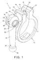
FIG. 1 is a perspective view illustrating a portion of a quick release device according to an embodiment of the invention; -
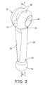
FIG. 2 is a perspective view of a lever arm of the quick release device; and -
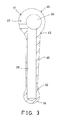
FIG. 3 is a cross sectional view of the lever arm of the quick release device taken along lines 3-3 ofFIG. 2 . - Referring to
FIG. 1 , aquick release device 1 comprises a C-shaped attachingmember 10 including achamber 11 for receiving handlebars, seat posts, wheel hubs, or other objects (not shown), aslot 15 formed between twoears aperture 14 formed through theears tie rod 20 which includes ahead 21 for engaging with one of theears 12 and which includes an outer orfree end 22 extended out of theother ear 13, and a wear-resist cam seat 23 attached to theend 22 of thetie rod 20 and contacted with theother ear 13, thecam seat 23 includes acurved recess 24 faced away from theother ear 13. Alever arm 30 includes acam 31 provided on oneend 33 for attaching to thefree end 22 of thetie rod 20 and for engaging with thecurved recess 24 of thecam seat 23. - The
longitudinal lever arm 30 includes a circular cross section, or includes a cylindrical shape (FIGS. 1-3 ), and includes one orfirst end 32 having a smaller outer diameter than the other orsecond end 33, ahand grip 34 provided on thefirst end 32, one or more flat surfaces 35 (FIG. 2 ) formed on the outer peripheral portion, and includes abore 36, such as a blind bore 36 (FIG. 3 ) formed through thelever arm 30, and includes thecam 31 provided on the other orsecond end 33. Thelever arm 30 includes achannel 37 formed in thecam 31 and communicating with thebore 36 for forming twolimbs 38 and for receiving thefree end 22 of thetie rod 20, and includes anorifice 39 formed in thecam 31 and communicating with thechannel 37 for receiving a shaft 40 (FIG. 1 ) which is perpendicular to thelever arm 30 and engaged through theorifice 39 of thelimbs 38 and thechannel 37 of thecam 31. Thefree end 22 of thetie rod 20 may be secured to theshaft 40 with latches or fasteners or threading engagements (not shown). - In operation, the
lever arm 30 may be pulled to actuate thecam 31 to secure or disengage theears 13 from the object. Thelever arm 30 is longitudinal having a circular cross section, or having a cylindrical shape, and having a bore 36 (FIG. 3 ) formed through thelever arm 30, and having a smaller one orfirst end 32 for increasing the stiffness and the bending strength of thelever arm 30 and for reducing the weight and the costs of thelever arm 30.
Claims (7)
- Quick release device comprising
an attaching member (10) including a chamber (11), a slot (15) formed between a first ear (12) and a second ear (13), an aperture (14) formed through the ears (12, 13),
a tie rod (20) engaged in the aperture (14) of the ears (12, 13) and including a head (21) engaged with the first ear (12) and including a free end (22),
a lever arm (30) including a first end (32) and a cam (31) formed on a second end (33) for engaging with the second ear (13), a channel (37) formed in the cam (31) for forming two limbs (38) and for receiving the free end (22) of the tie rod (20), an orifice (39) formed in the limbs (38), and
a shaft (40) received in the orifice (39) of the limbs (38) and extended through the channel (37) of the cam (31),
wherein the free end (22) of the tie rod (20) is secured to the shaft (40),
characterised in that
the lever arm (30) includes a bore (36) communicating with the channel (37) of the cam (31) and formed through the lever arm (30) in longitudinal direction, and
the first end (32) of the lever arm (30) includes a smaller outer diameter than that of the second end (33) of the lever arm (30). - Quick release device as claimed in claim 1, wherein the bore (36) of the lever arm (30) is a blind bore (36).
- Quick release device as claimed in claim 1 or 2, wherein the lever arm (30) includes a hand grip (34) provided on the first end (32).
- Quick release device as claimed in one of claims 1 to 3, wherein the lever arm (30) includes a circular-shaped cross section.
- Quick release device as claimed in one of claims 1 to 4, wherein the lever arm (30) includes a cylindrical shape.
- Quick release device as claimed in one of claims 1 to 5, wherein the lever arm (30) includes at least one flat surface (35) formed on an outer portion.
- Quick release device as claimed in one of claims 1 to 6, wherein a cam seat (23) is attached onto the free end (22) of the tie rod (20) and engaged with the second ear (13), and includes a curved recess (24) for engaging with the cam (31).
Priority Applications (3)
| Application Number | Priority Date | Filing Date | Title |
|---|---|---|---|
| ES09157734T ES2383190T3 (en) | 2009-04-09 | 2009-04-09 | Quick release device for bicycle |
| AT09157734T ATE542731T1 (en) | 2009-04-09 | 2009-04-09 | QUICK RELEASE DEVICE FOR BICYCLE |
| EP09157734A EP2248714B1 (en) | 2009-04-09 | 2009-04-09 | Quick Release Device for Bicycle |
Applications Claiming Priority (1)
| Application Number | Priority Date | Filing Date | Title |
|---|---|---|---|
| EP09157734A EP2248714B1 (en) | 2009-04-09 | 2009-04-09 | Quick Release Device for Bicycle |
Publications (2)
| Publication Number | Publication Date |
|---|---|
| EP2248714A1 EP2248714A1 (en) | 2010-11-10 |
| EP2248714B1 true EP2248714B1 (en) | 2012-01-25 |
Family
ID=40845861
Family Applications (1)
| Application Number | Title | Priority Date | Filing Date |
|---|---|---|---|
| EP09157734A Not-in-force EP2248714B1 (en) | 2009-04-09 | 2009-04-09 | Quick Release Device for Bicycle |
Country Status (3)
| Country | Link |
|---|---|
| EP (1) | EP2248714B1 (en) |
| AT (1) | ATE542731T1 (en) |
| ES (1) | ES2383190T3 (en) |
Families Citing this family (1)
| Publication number | Priority date | Publication date | Assignee | Title |
|---|---|---|---|---|
| FI122777B (en) * | 2010-11-29 | 2012-06-29 | Merivaara Oy | clamp |
Family Cites Families (4)
| Publication number | Priority date | Publication date | Assignee | Title |
|---|---|---|---|---|
| FR2352193A1 (en) | 1976-05-18 | 1977-12-16 | Meys Willy | DEVICE ALLOWING THE ADJUSTABLE BLOCKING OF A MOBILE PART FROM A FIXED FRAME |
| US5556222A (en) | 1995-02-08 | 1996-09-17 | Chen; Chun-Hsung | Quick release mechanism |
| DE29609092U1 (en) | 1996-05-21 | 1996-08-14 | Liu, Robert Z., Feng-Yuan, Taichung | Quick release set |
| US6948878B1 (en) | 2003-06-26 | 2005-09-27 | Grove Tools, Inc. | Locking quick release device |
-
2009
- 2009-04-09 AT AT09157734T patent/ATE542731T1/en active
- 2009-04-09 ES ES09157734T patent/ES2383190T3/en active Active
- 2009-04-09 EP EP09157734A patent/EP2248714B1/en not_active Not-in-force
Also Published As
| Publication number | Publication date |
|---|---|
| EP2248714A1 (en) | 2010-11-10 |
| ATE542731T1 (en) | 2012-02-15 |
| ES2383190T3 (en) | 2012-06-19 |
Similar Documents
| Publication | Publication Date | Title |
|---|---|---|
| USD555546S1 (en) | Quick release lever for a bicycle hub | |
| US8864143B2 (en) | Small outer diameter quick release extension rod | |
| US20110219908A1 (en) | Bicycle Stem | |
| CN105083450A (en) | Bicycle hydraulic operating device and bicycle hydraulic device assembly | |
| US8550437B2 (en) | Tool with working and positioning devices | |
| EP2151303B1 (en) | Positioning device for rotary wrench | |
| US8256983B2 (en) | Quick release device for bicycle | |
| US20050061587A1 (en) | Brake device having adjustable spring member | |
| WO2004004976A3 (en) | Bar clamp with side-activated braking lever | |
| US10463916B2 (en) | Active camming device | |
| US10259531B2 (en) | Bicycle front derailleur | |
| EP2934949B1 (en) | A clamping device for a bicycle rack | |
| US20060219063A1 (en) | Sprocket wrench | |
| EP2248714B1 (en) | Quick Release Device for Bicycle | |
| US8448298B2 (en) | Handle attachment for doorknobs | |
| WO2018154228A1 (en) | Percussive bell to be attached to a bicycle handlebar | |
| USD551054S1 (en) | Bicycle bar grip | |
| US20100111595A1 (en) | Quick release device for bicycle | |
| US20080257117A1 (en) | One-Way Ratchet Wrench | |
| EP2845789B1 (en) | Shifting structure for a bicycle | |
| US6095450A (en) | Pivot for a winding device | |
| JP2007276024A (en) | Adapter for use in pliers for remote operation | |
| US20110016684A1 (en) | Special tool used in a control arm of vehicles | |
| EP2103510B1 (en) | Bicycle accessory device | |
| JP2005511328A5 (en) |
Legal Events
| Date | Code | Title | Description |
|---|---|---|---|
| PUAI | Public reference made under article 153(3) epc to a published international application that has entered the european phase |
Free format text: ORIGINAL CODE: 0009012 |
|
| AK | Designated contracting states |
Kind code of ref document: A1 Designated state(s): AT BE BG CH CY CZ DE DK EE ES FI FR GB GR HR HU IE IS IT LI LT LU LV MC MK MT NL NO PL PT RO SE SI SK TR |
|
| AX | Request for extension of the european patent |
Extension state: AL BA RS |
|
| 17P | Request for examination filed |
Effective date: 20110510 |
|
| GRAP | Despatch of communication of intention to grant a patent |
Free format text: ORIGINAL CODE: EPIDOSNIGR1 |
|
| RIC1 | Information provided on ipc code assigned before grant |
Ipc: B62K 25/02 20060101ALI20110617BHEP Ipc: F16B 2/18 20060101ALI20110617BHEP Ipc: B62K 19/36 20060101ALI20110617BHEP Ipc: B62J 1/08 20060101AFI20110617BHEP |
|
| GRAS | Grant fee paid |
Free format text: ORIGINAL CODE: EPIDOSNIGR3 |
|
| GRAA | (expected) grant |
Free format text: ORIGINAL CODE: 0009210 |
|
| AK | Designated contracting states |
Kind code of ref document: B1 Designated state(s): AT BE BG CH CY CZ DE DK EE ES FI FR GB GR HR HU IE IS IT LI LT LU LV MC MK MT NL NO PL PT RO SE SI SK TR |
|
| REG | Reference to a national code |
Ref country code: GB Ref legal event code: FG4D |
|
| REG | Reference to a national code |
Ref country code: CH Ref legal event code: EP |
|
| REG | Reference to a national code |
Ref country code: AT Ref legal event code: REF Ref document number: 542731 Country of ref document: AT Kind code of ref document: T Effective date: 20120215 |
|
| REG | Reference to a national code |
Ref country code: IE Ref legal event code: FG4D |
|
| REG | Reference to a national code |
Ref country code: DE Ref legal event code: R096 Ref document number: 602009004860 Country of ref document: DE Effective date: 20120322 |
|
| REG | Reference to a national code |
Ref country code: NL Ref legal event code: VDEP Effective date: 20120125 |
|
| REG | Reference to a national code |
Ref country code: CH Ref legal event code: NV Representative=s name: P&TS SA |
|
| REG | Reference to a national code |
Ref country code: ES Ref legal event code: FG2A Ref document number: 2383190 Country of ref document: ES Kind code of ref document: T3 Effective date: 20120619 |
|
| LTIE | Lt: invalidation of european patent or patent extension |
Effective date: 20120125 |
|
| PG25 | Lapsed in a contracting state [announced via postgrant information from national office to epo] |
Ref country code: IS Free format text: LAPSE BECAUSE OF FAILURE TO SUBMIT A TRANSLATION OF THE DESCRIPTION OR TO PAY THE FEE WITHIN THE PRESCRIBED TIME-LIMIT Effective date: 20120525 Ref country code: BG Free format text: LAPSE BECAUSE OF FAILURE TO SUBMIT A TRANSLATION OF THE DESCRIPTION OR TO PAY THE FEE WITHIN THE PRESCRIBED TIME-LIMIT Effective date: 20120425 Ref country code: NO Free format text: LAPSE BECAUSE OF FAILURE TO SUBMIT A TRANSLATION OF THE DESCRIPTION OR TO PAY THE FEE WITHIN THE PRESCRIBED TIME-LIMIT Effective date: 20120425 Ref country code: NL Free format text: LAPSE BECAUSE OF FAILURE TO SUBMIT A TRANSLATION OF THE DESCRIPTION OR TO PAY THE FEE WITHIN THE PRESCRIBED TIME-LIMIT Effective date: 20120125 Ref country code: LT Free format text: LAPSE BECAUSE OF FAILURE TO SUBMIT A TRANSLATION OF THE DESCRIPTION OR TO PAY THE FEE WITHIN THE PRESCRIBED TIME-LIMIT Effective date: 20120125 Ref country code: BE Free format text: LAPSE BECAUSE OF FAILURE TO SUBMIT A TRANSLATION OF THE DESCRIPTION OR TO PAY THE FEE WITHIN THE PRESCRIBED TIME-LIMIT Effective date: 20120125 Ref country code: HR Free format text: LAPSE BECAUSE OF FAILURE TO SUBMIT A TRANSLATION OF THE DESCRIPTION OR TO PAY THE FEE WITHIN THE PRESCRIBED TIME-LIMIT Effective date: 20120125 |
|
| PG25 | Lapsed in a contracting state [announced via postgrant information from national office to epo] |
Ref country code: LV Free format text: LAPSE BECAUSE OF FAILURE TO SUBMIT A TRANSLATION OF THE DESCRIPTION OR TO PAY THE FEE WITHIN THE PRESCRIBED TIME-LIMIT Effective date: 20120125 Ref country code: PL Free format text: LAPSE BECAUSE OF FAILURE TO SUBMIT A TRANSLATION OF THE DESCRIPTION OR TO PAY THE FEE WITHIN THE PRESCRIBED TIME-LIMIT Effective date: 20120125 Ref country code: GR Free format text: LAPSE BECAUSE OF FAILURE TO SUBMIT A TRANSLATION OF THE DESCRIPTION OR TO PAY THE FEE WITHIN THE PRESCRIBED TIME-LIMIT Effective date: 20120426 Ref country code: FI Free format text: LAPSE BECAUSE OF FAILURE TO SUBMIT A TRANSLATION OF THE DESCRIPTION OR TO PAY THE FEE WITHIN THE PRESCRIBED TIME-LIMIT Effective date: 20120125 Ref country code: PT Free format text: LAPSE BECAUSE OF FAILURE TO SUBMIT A TRANSLATION OF THE DESCRIPTION OR TO PAY THE FEE WITHIN THE PRESCRIBED TIME-LIMIT Effective date: 20120525 |
|
| REG | Reference to a national code |
Ref country code: AT Ref legal event code: MK05 Ref document number: 542731 Country of ref document: AT Kind code of ref document: T Effective date: 20120125 |
|
| PG25 | Lapsed in a contracting state [announced via postgrant information from national office to epo] |
Ref country code: CY Free format text: LAPSE BECAUSE OF FAILURE TO SUBMIT A TRANSLATION OF THE DESCRIPTION OR TO PAY THE FEE WITHIN THE PRESCRIBED TIME-LIMIT Effective date: 20120125 |
|
| PG25 | Lapsed in a contracting state [announced via postgrant information from national office to epo] |
Ref country code: SE Free format text: LAPSE BECAUSE OF FAILURE TO SUBMIT A TRANSLATION OF THE DESCRIPTION OR TO PAY THE FEE WITHIN THE PRESCRIBED TIME-LIMIT Effective date: 20120125 Ref country code: EE Free format text: LAPSE BECAUSE OF FAILURE TO SUBMIT A TRANSLATION OF THE DESCRIPTION OR TO PAY THE FEE WITHIN THE PRESCRIBED TIME-LIMIT Effective date: 20120125 Ref country code: RO Free format text: LAPSE BECAUSE OF FAILURE TO SUBMIT A TRANSLATION OF THE DESCRIPTION OR TO PAY THE FEE WITHIN THE PRESCRIBED TIME-LIMIT Effective date: 20120125 Ref country code: DK Free format text: LAPSE BECAUSE OF FAILURE TO SUBMIT A TRANSLATION OF THE DESCRIPTION OR TO PAY THE FEE WITHIN THE PRESCRIBED TIME-LIMIT Effective date: 20120125 Ref country code: SI Free format text: LAPSE BECAUSE OF FAILURE TO SUBMIT A TRANSLATION OF THE DESCRIPTION OR TO PAY THE FEE WITHIN THE PRESCRIBED TIME-LIMIT Effective date: 20120125 Ref country code: CZ Free format text: LAPSE BECAUSE OF FAILURE TO SUBMIT A TRANSLATION OF THE DESCRIPTION OR TO PAY THE FEE WITHIN THE PRESCRIBED TIME-LIMIT Effective date: 20120125 |
|
| PG25 | Lapsed in a contracting state [announced via postgrant information from national office to epo] |
Ref country code: SK Free format text: LAPSE BECAUSE OF FAILURE TO SUBMIT A TRANSLATION OF THE DESCRIPTION OR TO PAY THE FEE WITHIN THE PRESCRIBED TIME-LIMIT Effective date: 20120125 Ref country code: MC Free format text: LAPSE BECAUSE OF NON-PAYMENT OF DUE FEES Effective date: 20120430 |
|
| PLBE | No opposition filed within time limit |
Free format text: ORIGINAL CODE: 0009261 |
|
| STAA | Information on the status of an ep patent application or granted ep patent |
Free format text: STATUS: NO OPPOSITION FILED WITHIN TIME LIMIT |
|
| 26N | No opposition filed |
Effective date: 20121026 |
|
| REG | Reference to a national code |
Ref country code: IE Ref legal event code: MM4A |
|
| PG25 | Lapsed in a contracting state [announced via postgrant information from national office to epo] |
Ref country code: AT Free format text: LAPSE BECAUSE OF FAILURE TO SUBMIT A TRANSLATION OF THE DESCRIPTION OR TO PAY THE FEE WITHIN THE PRESCRIBED TIME-LIMIT Effective date: 20120125 Ref country code: IE Free format text: LAPSE BECAUSE OF NON-PAYMENT OF DUE FEES Effective date: 20120409 |
|
| REG | Reference to a national code |
Ref country code: DE Ref legal event code: R097 Ref document number: 602009004860 Country of ref document: DE Effective date: 20121026 |
|
| PG25 | Lapsed in a contracting state [announced via postgrant information from national office to epo] |
Ref country code: MK Free format text: LAPSE BECAUSE OF FAILURE TO SUBMIT A TRANSLATION OF THE DESCRIPTION OR TO PAY THE FEE WITHIN THE PRESCRIBED TIME-LIMIT Effective date: 20120125 |
|
| PG25 | Lapsed in a contracting state [announced via postgrant information from national office to epo] |
Ref country code: MT Free format text: LAPSE BECAUSE OF FAILURE TO SUBMIT A TRANSLATION OF THE DESCRIPTION OR TO PAY THE FEE WITHIN THE PRESCRIBED TIME-LIMIT Effective date: 20120125 |
|
| PG25 | Lapsed in a contracting state [announced via postgrant information from national office to epo] |
Ref country code: TR Free format text: LAPSE BECAUSE OF FAILURE TO SUBMIT A TRANSLATION OF THE DESCRIPTION OR TO PAY THE FEE WITHIN THE PRESCRIBED TIME-LIMIT Effective date: 20120125 |
|
| PG25 | Lapsed in a contracting state [announced via postgrant information from national office to epo] |
Ref country code: LU Free format text: LAPSE BECAUSE OF NON-PAYMENT OF DUE FEES Effective date: 20120409 |
|
| PG25 | Lapsed in a contracting state [announced via postgrant information from national office to epo] |
Ref country code: HU Free format text: LAPSE BECAUSE OF FAILURE TO SUBMIT A TRANSLATION OF THE DESCRIPTION OR TO PAY THE FEE WITHIN THE PRESCRIBED TIME-LIMIT Effective date: 20090409 |
|
| REG | Reference to a national code |
Ref country code: FR Ref legal event code: PLFP Year of fee payment: 7 |
|
| PGFP | Annual fee paid to national office [announced via postgrant information from national office to epo] |
Ref country code: GB Payment date: 20150212 Year of fee payment: 7 |
|
| PGFP | Annual fee paid to national office [announced via postgrant information from national office to epo] |
Ref country code: ES Payment date: 20150427 Year of fee payment: 7 Ref country code: CH Payment date: 20150427 Year of fee payment: 7 Ref country code: DE Payment date: 20150429 Year of fee payment: 7 |
|
| PGFP | Annual fee paid to national office [announced via postgrant information from national office to epo] |
Ref country code: IT Payment date: 20150429 Year of fee payment: 7 Ref country code: FR Payment date: 20150417 Year of fee payment: 7 |
|
| REG | Reference to a national code |
Ref country code: DE Ref legal event code: R119 Ref document number: 602009004860 Country of ref document: DE |
|
| REG | Reference to a national code |
Ref country code: CH Ref legal event code: PL |
|
| GBPC | Gb: european patent ceased through non-payment of renewal fee |
Effective date: 20160409 |
|
| REG | Reference to a national code |
Ref country code: FR Ref legal event code: ST Effective date: 20161230 |
|
| PG25 | Lapsed in a contracting state [announced via postgrant information from national office to epo] |
Ref country code: GB Free format text: LAPSE BECAUSE OF NON-PAYMENT OF DUE FEES Effective date: 20160409 Ref country code: FR Free format text: LAPSE BECAUSE OF NON-PAYMENT OF DUE FEES Effective date: 20160502 Ref country code: CH Free format text: LAPSE BECAUSE OF NON-PAYMENT OF DUE FEES Effective date: 20160430 Ref country code: DE Free format text: LAPSE BECAUSE OF NON-PAYMENT OF DUE FEES Effective date: 20161101 Ref country code: LI Free format text: LAPSE BECAUSE OF NON-PAYMENT OF DUE FEES Effective date: 20160430 |
|
| PG25 | Lapsed in a contracting state [announced via postgrant information from national office to epo] |
Ref country code: IT Free format text: LAPSE BECAUSE OF NON-PAYMENT OF DUE FEES Effective date: 20160409 |
|
| PG25 | Lapsed in a contracting state [announced via postgrant information from national office to epo] |
Ref country code: ES Free format text: LAPSE BECAUSE OF NON-PAYMENT OF DUE FEES Effective date: 20160410 |
|
| REG | Reference to a national code |
Ref country code: ES Ref legal event code: FD2A Effective date: 20181129 |