EP2248624A1 - Method of beam welding two members using vented shim; corresponding vented shim - Google Patents
Method of beam welding two members using vented shim; corresponding vented shim Download PDFInfo
- Publication number
- EP2248624A1 EP2248624A1 EP10161570A EP10161570A EP2248624A1 EP 2248624 A1 EP2248624 A1 EP 2248624A1 EP 10161570 A EP10161570 A EP 10161570A EP 10161570 A EP10161570 A EP 10161570A EP 2248624 A1 EP2248624 A1 EP 2248624A1
- Authority
- EP
- European Patent Office
- Prior art keywords
- shim
- metallic material
- members
- weld
- beam welding
- Prior art date
- Legal status (The legal status is an assumption and is not a legal conclusion. Google has not performed a legal analysis and makes no representation as to the accuracy of the status listed.)
- Granted
Links
Images


Classifications
-
- B—PERFORMING OPERATIONS; TRANSPORTING
- B23—MACHINE TOOLS; METAL-WORKING NOT OTHERWISE PROVIDED FOR
- B23K—SOLDERING OR UNSOLDERING; WELDING; CLADDING OR PLATING BY SOLDERING OR WELDING; CUTTING BY APPLYING HEAT LOCALLY, e.g. FLAME CUTTING; WORKING BY LASER BEAM
- B23K26/00—Working by laser beam, e.g. welding, cutting or boring
- B23K26/20—Bonding
- B23K26/21—Bonding by welding
- B23K26/24—Seam welding
- B23K26/26—Seam welding of rectilinear seams
-
- B—PERFORMING OPERATIONS; TRANSPORTING
- B23—MACHINE TOOLS; METAL-WORKING NOT OTHERWISE PROVIDED FOR
- B23K—SOLDERING OR UNSOLDERING; WELDING; CLADDING OR PLATING BY SOLDERING OR WELDING; CUTTING BY APPLYING HEAT LOCALLY, e.g. FLAME CUTTING; WORKING BY LASER BEAM
- B23K15/00—Electron-beam welding or cutting
- B23K15/0046—Welding
- B23K15/0053—Seam welding
- B23K15/006—Seam welding of rectilinear seams
-
- B—PERFORMING OPERATIONS; TRANSPORTING
- B23—MACHINE TOOLS; METAL-WORKING NOT OTHERWISE PROVIDED FOR
- B23K—SOLDERING OR UNSOLDERING; WELDING; CLADDING OR PLATING BY SOLDERING OR WELDING; CUTTING BY APPLYING HEAT LOCALLY, e.g. FLAME CUTTING; WORKING BY LASER BEAM
- B23K15/00—Electron-beam welding or cutting
- B23K15/0046—Welding
- B23K15/0053—Seam welding
- B23K15/0073—Seam welding with interposition of particular material to facilitate connecting the parts, e.g. using a filler
-
- B—PERFORMING OPERATIONS; TRANSPORTING
- B23—MACHINE TOOLS; METAL-WORKING NOT OTHERWISE PROVIDED FOR
- B23K—SOLDERING OR UNSOLDERING; WELDING; CLADDING OR PLATING BY SOLDERING OR WELDING; CUTTING BY APPLYING HEAT LOCALLY, e.g. FLAME CUTTING; WORKING BY LASER BEAM
- B23K15/00—Electron-beam welding or cutting
- B23K15/0046—Welding
- B23K15/0093—Welding characterised by the properties of the materials to be welded
-
- B—PERFORMING OPERATIONS; TRANSPORTING
- B23—MACHINE TOOLS; METAL-WORKING NOT OTHERWISE PROVIDED FOR
- B23K—SOLDERING OR UNSOLDERING; WELDING; CLADDING OR PLATING BY SOLDERING OR WELDING; CUTTING BY APPLYING HEAT LOCALLY, e.g. FLAME CUTTING; WORKING BY LASER BEAM
- B23K26/00—Working by laser beam, e.g. welding, cutting or boring
- B23K26/20—Bonding
- B23K26/21—Bonding by welding
- B23K26/211—Bonding by welding with interposition of special material to facilitate connection of the parts
-
- B—PERFORMING OPERATIONS; TRANSPORTING
- B23—MACHINE TOOLS; METAL-WORKING NOT OTHERWISE PROVIDED FOR
- B23K—SOLDERING OR UNSOLDERING; WELDING; CLADDING OR PLATING BY SOLDERING OR WELDING; CUTTING BY APPLYING HEAT LOCALLY, e.g. FLAME CUTTING; WORKING BY LASER BEAM
- B23K2101/00—Articles made by soldering, welding or cutting
- B23K2101/18—Sheet panels
-
- F—MECHANICAL ENGINEERING; LIGHTING; HEATING; WEAPONS; BLASTING
- F16—ENGINEERING ELEMENTS AND UNITS; GENERAL MEASURES FOR PRODUCING AND MAINTAINING EFFECTIVE FUNCTIONING OF MACHINES OR INSTALLATIONS; THERMAL INSULATION IN GENERAL
- F16B—DEVICES FOR FASTENING OR SECURING CONSTRUCTIONAL ELEMENTS OR MACHINE PARTS TOGETHER, e.g. NAILS, BOLTS, CIRCLIPS, CLAMPS, CLIPS OR WEDGES; JOINTS OR JOINTING
- F16B5/00—Joining sheets or plates, e.g. panels, to one another or to strips or bars parallel to them
- F16B5/08—Joining sheets or plates, e.g. panels, to one another or to strips or bars parallel to them by means of welds or the like
Definitions
- a weld containing porosity may be formed when materials are beam welded together and there is no mechanism for gases that are created during the welding process to escape from the weld pool.
- the formation of a weld containing porosity may be more likely to be formed when thick pieces of materials are joined. The thicker a piece of material, the greater likelihood that during welding that there will be the formation of gases that evolved during the welding process that are unable to escape and thus result in the formation of a weld containing porosity.
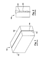
- FIG. 1 shows an illustrative prior art approach to welding two material members 102 together using a shim 104.
- FIG. 1 shows how shim 104 is placed along a weld joint faying surface 106 between the two material members 102.
- FIG. 2 shows the prior art including a cross-sectional view of a weld 204 containing porosity 202.
- a method and system are disclosed for beam welding two members made of a metallic material.
- the method comprising placing a first shim along a weld joint faying surface between the two members of the metallic material, placing a second shim along the weld joint faying surface between the two members of the metallic material and at a distance from the first shim to create a first vent path between the first and the second shim and beam welding the members of the metallic material with the shims to create a porosity free weld.
- a first aspect of the invention provides a method for beam welding two members made of a metallic material, the method comprising placing a first shim along a weld joint faying surface between the two members of the metallic material, placing a second shim along the weld joint faying surface between the two members of the material and at a distance from the first shim to create a first vent path between the first and the second shim and beam welding the members of the metallic material with the shims to create a porosity free weld.
- a second aspect of the invention provides a welding shim system for use in welding two members of metallic y material, the system comprising a first shim having an angled edge for placement within a plane of a weld joint faying surface between the two members of the metallic material, a second shim having a complementary angled edge to the angled edge of the first shim for placement within the plane of the weld joint faying surface between the two members of the metallic material and an element on at least one of the first and second shims for positioning the shims such that a first vent path exists between the angled edge and the complimentary angled edge.
- FIG. 3 shows an embodiment of the invention wherein there is a metallic material member 102 that includes a welding joint faying surface 106, and a first metallic shim 302 adjacent to a second metallic shim 306 with a first vent path 304 therebetween. Gases created during the welding process may be removed from the metallic material member 102 ahead of the weld pool through vent path 304.
- a welding shim system for use in welding two members 102 of metallic material.
- the system may comprise first metallic shim 302 having an angled edge 310 for placement within a plane of weld joint faying surface 106 between the two members 102 of the metallic material, a second metallic shim 306 having a complementary angled edge 312 to angled edge 310 of first metallic shim 302 for placement within the plane of the weld joint faying surface 106 between the two members 102 of the metallic material.
- the system may have an element 314 on at least one of first metallic shim 302 or second metallic shim 306 for positioning the shims such that first vent path 304 exists between angled edge 310 and complimentary angled edge 312.
- first shim 302 and second shim 306 each include a metallic material.
- the material of the shim, the angle cut on the shim, and the gap spacing of the shim are correlated to the welding parameters and the metallic material being joined.
- the welding parameters may include, as an example, controlling the power to the electron beam, current to the electron beam, travel speed of the beam, oscillation, frequency and focus.
- each metallic shim has a substantially parallelogram shape.
- angle edge 310 and complimentary angle edge 312 are approximately 20 to 60 degrees relative to a beam welding angle.
- a third metallic shim 309 or any number of additional shims may be provided having a second complementary angled edge 316 to a second angle edge 315 of an adjacent second shim 306 (in this case, second metallic shim) for placement within the plane of the weld joint faying surface 106 between the two members 102 of the metallic material.
- An element 318 may be provided on at least one of second shim 306 or third shim 309 for positioning the shims such that a second vent path 308 exists between second complimentary angled edge 318 and second angled edge 315.
- First vent path 304 and second vent path 308 allow gases created during the welding process to escape ahead of the weld pool.
- the first shim and the second shim may be separated from one another by a space of up to 0.100 inch.
- gases created during the welding process may be channeled through vent paths 304, 308 ahead of the weld pool. Allowing the gases to escape during the welding process may reduce or eliminate the creation of a weld containing porosity 202 ( FIG. 2 ). Consequently, allowing the gases from the welding process to be channeled away through vent paths 304, 308 may result in a porosity free weld, as illustrated in FIG. 4 .
- a porosity free weld 402 is a preferred weld between two or more metallic materials.
- FIG. 5 an additional embodiment where a beam welder 504 would weld two metallic material members 102 using shims 302, 306 that have vent path 304 between adjacent shims 302, 306 is illustrated.
- a weld front 508 contacts second shim 306 and second vent path 308 before reaching an end 303 of the first vent path 304. That is, first vent path 304 terminates sufficiently close enough to second vent path 308 such that a vent path is always available.
- shims 302, 306 By aligning the shims 302, 306 along weld joint faying surface 106 so there is always vent path 304, 308 for the escape of gases 506 from beam welder 504, shims 302, 306 reduce the possibility of creating a weld with porosity 202 ( FIG. 2 ) and increases the likelihood of producing a porosity free weld 402 ( FIG. 4 ).
- the weld of metallic material members 102 and shim 104 can be made using a beam weld 504.
- the beam weld 504 can be an electron beam.
- the beam weld 504 can be a laser beam.
Landscapes
- Engineering & Computer Science (AREA)
- Mechanical Engineering (AREA)
- Physics & Mathematics (AREA)
- Optics & Photonics (AREA)
- Plasma & Fusion (AREA)
- Chemical & Material Sciences (AREA)
- Materials Engineering (AREA)
- Welding Or Cutting Using Electron Beams (AREA)
- Laser Beam Processing (AREA)
Abstract
Description
- The subject matter disclosed herein relates generally to welding and more specifically to a vented shim beam welding process. A weld containing porosity may be formed when materials are beam welded together and there is no mechanism for gases that are created during the welding process to escape from the weld pool. The formation of a weld containing porosity may be more likely to be formed when thick pieces of materials are joined. The thicker a piece of material, the greater likelihood that during welding that there will be the formation of gases that evolved during the welding process that are unable to escape and thus result in the formation of a weld containing porosity.
-
FIG. 1 shows an illustrative prior art approach to welding twomaterial members 102 together using ashim 104.FIG. 1 shows howshim 104 is placed along a weld joint fayingsurface 106 between the twomaterial members 102.FIG. 2 shows the prior art including a cross-sectional view of aweld 204 containingporosity 202. - A method and system are disclosed for beam welding two members made of a metallic material. The method comprising placing a first shim along a weld joint faying surface between the two members of the metallic material, placing a second shim along the weld joint faying surface between the two members of the metallic material and at a distance from the first shim to create a first vent path between the first and the second shim and beam welding the members of the metallic material with the shims to create a porosity free weld.
- A first aspect of the invention provides a method for beam welding two members made of a metallic material, the method comprising placing a first shim along a weld joint faying surface between the two members of the metallic material, placing a second shim along the weld joint faying surface between the two members of the material and at a distance from the first shim to create a first vent path between the first and the second shim and beam welding the members of the metallic material with the shims to create a porosity free weld.
- A second aspect of the invention provides a welding shim system for use in welding two members of metallic y material, the system comprising a first shim having an angled edge for placement within a plane of a weld joint faying surface between the two members of the metallic material, a second shim having a complementary angled edge to the angled edge of the first shim for placement within the plane of the weld joint faying surface between the two members of the metallic material and an element on at least one of the first and second shims for positioning the shims such that a first vent path exists between the angled edge and the complimentary angled edge.
- There follows a detailed description of embodiments of the invention by way of example only with reference to the accompanying drawings, in which:
-
FIG. 1 shows a perspective view of two members made of a metallic material with a shim therebetween according to the prior art. -
FIG. 2 shows a cross-sectional view of the members ofFIG. 1 illustrating the joint formed between the members and the porosity entrapped in the weld metal. -
FIG. 3 shows a perspective view of a member made of a metallic material with shims that include vent paths between the shims. -
FIG. 4 shows a cross-sectional view of a porosity free joint formed using the shims ofFIG. 3 . -
FIG. 5 shows a cross-sectional view of two members made of a metallic material being beam welded with one of the members in phantom to expose the weld progression. - It is noted that the drawings are not to scale. The drawings are intended to depict only typical aspects of the invention, and therefore should not be considered as limiting the scope of the invention. In the drawings, like numbering represents like elements between the drawings.
- The removal of gases created during the welding of metallic materials is advantageous to the welding process as it reduces the possible formation of porosity in the weld. One way to remove these gases is through a vent path that is created using shims. The shims may already be present as part of the welding process. The shims may be arranged to create a vent path for the removal of gases created during welding. Turning to the drawings,
FIG. 3 shows an embodiment of the invention wherein there is ametallic material member 102 that includes a welding jointfaying surface 106, and a firstmetallic shim 302 adjacent to a secondmetallic shim 306 with afirst vent path 304 therebetween. Gases created during the welding process may be removed from themetallic material member 102 ahead of the weld pool throughvent path 304. - In one embodiment, there is a welding shim system for use in welding two
members 102 of metallic material. The system may comprise firstmetallic shim 302 having anangled edge 310 for placement within a plane of weld joint fayingsurface 106 between the twomembers 102 of the metallic material, a secondmetallic shim 306 having a complementaryangled edge 312 toangled edge 310 of firstmetallic shim 302 for placement within the plane of the weld joint fayingsurface 106 between the twomembers 102 of the metallic material. Additionally, the system may have anelement 314 on at least one of firstmetallic shim 302 or secondmetallic shim 306 for positioning the shims such thatfirst vent path 304 exists betweenangled edge 310 and complimentaryangled edge 312. In an additional embodiment,first shim 302 andsecond shim 306 each include a metallic material. The material of the shim, the angle cut on the shim, and the gap spacing of the shim are correlated to the welding parameters and the metallic material being joined. The welding parameters may include, as an example, controlling the power to the electron beam, current to the electron beam, travel speed of the beam, oscillation, frequency and focus. In an alternative embodiment, each metallic shim has a substantially parallelogram shape. In a further embodiment,angle edge 310 andcomplimentary angle edge 312 are approximately 20 to 60 degrees relative to a beam welding angle. - In a further embodiment, a third
metallic shim 309 or any number of additional shims may be provided having a second complementaryangled edge 316 to asecond angle edge 315 of an adjacent second shim 306 (in this case, second metallic shim) for placement within the plane of the weld joint fayingsurface 106 between the twomembers 102 of the metallic material. Anelement 318 may be provided on at least one ofsecond shim 306 orthird shim 309 for positioning the shims such that asecond vent path 308 exists between second complimentaryangled edge 318 and secondangled edge 315. -
First vent path 304 andsecond vent path 308 allow gases created during the welding process to escape ahead of the weld pool. In one embodiment, the first shim and the second shim may be separated from one another by a space of up to 0.100 inch. As welding progresses alongmetallic material member 102, gases created during the welding process may be channeled throughvent paths FIG. 2 ). Consequently, allowing the gases from the welding process to be channeled away throughvent paths FIG. 4 . A porosityfree weld 402 is a preferred weld between two or more metallic materials. - Turning to
FIG. 5 , an additional embodiment where abeam welder 504 would weld twometallic material members 102 usingshims vent path 304 betweenadjacent shims beam welder 504 progresses alongmetallic material member 102, it produces a porosityfree weld 502. Asbeam welder 504 progresses alongmetallic material member 102, aweld front 508 contactssecond shim 306 andsecond vent path 308 before reaching anend 303 of thefirst vent path 304. That is,first vent path 304 terminates sufficiently close enough tosecond vent path 308 such that a vent path is always available. This process ensures that at every stage,welding gases 506 produced by the welding process are able to be channeled out ahead of theweld pool 510. By aligning theshims faying surface 106 so there is alwaysvent path gases 506 frombeam welder 504,shims FIG. 2 ) and increases the likelihood of producing a porosity free weld 402 (FIG. 4 ). The weld ofmetallic material members 102 andshim 104 can be made using abeam weld 504. In one embodiment, thebeam weld 504 can be an electron beam. In an alternative embodiment, thebeam weld 504 can be a laser beam. - The foregoing description of various aspects of the invention has been presented for purposes of illustration and description. It is not intended to be exhaustive or to limit the invention to the precise form disclosed, and obviously, many modifications and variations are possible. Such modifications and variations that may be apparent to an individual in the art are included within the scope of the invention as defined by the accompanying claims.
- Various aspects and embodiments of the present invention are defined by the following numbered clauses:
- 1. A method of beam welding two members made of a metallic material, the method comprising:
- placing a first shim along a weld joint faying surface between the two members of the metallic material;
- placing a second shim along the weld joint faying surface between the two members of the metallic material and at a distance from the first shim to create a first vent path between the first and the second shim; and
- beam welding the members of the metallic material with the shims to create a porosity free weld.
- 2. The method of clause 1, wherein the first and the second shim each include a metallic material.
- 3. The method of clause 1, further comprising placing a third shim along the weld joint faying surface and at a distance from the second shim to create a second vent path between the second and the third shim.
- 4. The method of clause 3, further comprising aligning the first vent path with the weld joint faying surface such that as the first vent path is consumed by a weld pool, the second vent path is available to provide a channel for gases from the welding to escape ahead of the weld pool.
- 5. The method of clause 1, wherein the first shim and the second shim are separated from one another by a space of up to 0.100 inch.
- 6. The method of clause 1, wherein the beam welding includes controlling power to a beam welder based on the metallic material being joined.
- 7. The method of clause 1, wherein the beam welding includes controlling current to a beam welder based on the metallic material being joined.
- 8. The method of clause 1, wherein the beam welding includes controlling a travel speed of a beam welder based on the metallic material being joined.
- 9. The method of clause 1, wherein the angle edge and the complementary angle edge are approximately 20 to 60 degrees relative to a beam welding angle.
- 10. The method of clause 1, wherein the beam welding includes using electron beam welding.
- 11. The method of clause 1, wherein the beam welding includes using laser beam welding.
- 12. A welding shim system for use in welding two members of a metallic material, the system comprising:
- a first shim having an angled edge for placement within a plane of a weld joint faying surface between the two members of the metallic material;
- a second shim having a complementary angled edge to the angled edge of the first shim for placement within the plane of the weld joint faying surface between the two members of the metallic material; and
- an element on at least one of the first and second shims for positioning the shims such that a first vent path exists between the angled edge and the complimentary angled edge.
- 13. The system of clause 12, wherein the first and the second shim each include a metallic material.
- 14. The system of clause 12, further comprising a third shim having a second complementary angled edge to a second angle edge of the second shim for placement within the plane of the weld joint faying surface between the two members of the metallic material.
- 15. The system of clause 14, further comprising an element on at least one of the second and third shims for positioning the shims such that a second vent path exists between the second complimentary angled edge and the second angled edge.
- 16. The system of clause 12, wherein the angled edge and the complimentary angled edge are separated from one another by a space of up to 0.100 inch.
- 17. The system of clause 12, wherein each shim has a substantially parallelogram shape.
- 18. The system of clause 12, wherein the angle edge and the complementary angle edge are approximately 20 to 60 degrees relative to a beam welding angle.
Claims (15)
- A method of beam welding two members (102) made of a metallic material, the method comprising:placing a first shim (302) along a weld joint faying surface (106) between the two members (102) of the metallic material;placing a second shim (306) along the weld joint faying surface (106) between the two members (102) of the metallic material and at a distance from the first shim (302) to create a first vent path (304) between the first and the second shim (306); and
beam welding the members (102) of the metallic material with the shims (302, 306) to create a porosity free weld (402, 502). - The method of claim 1, wherein the first and the second shim (302, 306) each include a metallic material.
- The method of claim 1 or 2, further comprising placing a third shim (309) along the weld joint faying surface (106) and at a distance from the second shim (306) to create a second vent path (308) between the second and the third shim (306, 309).
- The method of claim 3, further comprising aligning the first vent path (304) with the weld joint faying surface (106) such that as the first vent path (304) is consumed by a weld pool (510), the second vent path (308) is available to provide a channel for gases (506) from the welding to escape ahead of the weld pool (510).
- The method of any of the preceding claims, wherein the first shim (302) and the second shim (306) are separated from one another by a space of up to 0.100 inch.
- The method of any of the preceding claims, wherein the beam welding includes controlling power to a beam welder (504) based on the metallic material being joined.
- The method of any of the preceding claims, wherein the beam welding includes controlling current to a beam welder (504) based on the metallic material being joined.
- The method of any of the preceding claims, wherein the beam welding includes controlling a travel speed of a beam welder (504) based on the metallic material being joined.
- The method of any of the preceding claims, wherein the angle edge (310) and the complementary angle edge (312) are approximately 20 to 60 degrees relative to a beam welding angle.
- The method of any of the preceding claims, wherein the beam welding includes using electron beam welding.
- The method of any of the preceding claims, wherein the beam welding includes using laser beam welding.
- A welding shim system for use in welding two members (102) of a metallic material, the system comprising:a first shim (302) having an angled edge (310) for placement within a plane of a weld joint faying surface (106) between the two members (102) of the metallic material;a second shim (306) having a complementary angled edge (312) to the angled edge (310) of the first shim (302) for placement within the plane of the weld joint faying surface (106) between the two members (102) of the metallic material; and
an element (314, 318) on at least one of the first and second shims (302, 306) for positioning the shims (302, 306) such that a first vent path (304) exists between the angled edge (310) and the complimentary angled edge (312). - The system of claim 12, wherein the first and the second shim (302, 306) each include a metallic material.
- The system of claim 12 or 13, further comprising a third shim (309) having a second complementary angled edge (316, 318) to a second angle edge (315) of the second shim (306) for placement within the plane of the weld joint faying surface (106) between the two members (102) of the metallic material.
- The system of claim 14, further comprising an element (318) on at least one of the second and third shim (302, 306) for positioning the shims (302, 306) such that a second vent path (308) exists between the second complimentary angled edge (316, 318) and the second angled edge (310).
Applications Claiming Priority (1)
| Application Number | Priority Date | Filing Date | Title |
|---|---|---|---|
| US12/435,430 US20100282719A1 (en) | 2009-05-05 | 2009-05-05 | Vented shim beam welding process |
Publications (2)
| Publication Number | Publication Date |
|---|---|
| EP2248624A1 true EP2248624A1 (en) | 2010-11-10 |
| EP2248624B1 EP2248624B1 (en) | 2014-01-01 |
Family
ID=42313515
Family Applications (1)
| Application Number | Title | Priority Date | Filing Date |
|---|---|---|---|
| EP10161570.6A Not-in-force EP2248624B1 (en) | 2009-05-05 | 2010-04-30 | Method of beam welding two members using vented shims ; corresponding beam welder and vented shims |
Country Status (3)
| Country | Link |
|---|---|
| US (1) | US20100282719A1 (en) |
| EP (1) | EP2248624B1 (en) |
| JP (1) | JP5615028B2 (en) |
Cited By (3)
| Publication number | Priority date | Publication date | Assignee | Title |
|---|---|---|---|---|
| EP2316607A1 (en) * | 2009-10-27 | 2011-05-04 | General Electric Company | Workpiece with channel and process of welding for preventing porosity in a formed weld |
| CN108890131A (en) * | 2018-09-25 | 2018-11-27 | 长沙理工大学 | A method of the Laser Deep Penetration Welding jointed sheet material based on prefabricated runner |
| CN113351992A (en) * | 2020-03-06 | 2021-09-07 | 通用汽车环球科技运作有限责任公司 | Welding system and method with knurled welding interface for metal workpieces |
Families Citing this family (4)
| Publication number | Priority date | Publication date | Assignee | Title |
|---|---|---|---|---|
| US20100282719A1 (en) * | 2009-05-05 | 2010-11-11 | General Electric Company | Vented shim beam welding process |
| RU2642218C1 (en) * | 2017-02-02 | 2018-01-24 | Публичное акционерное общество "Челябинский трубопрокатный завод" (ПАО "ЧТПЗ") | Method of laser welding of longitudinal pipe seam (versions) |
| CN110883407A (en) * | 2019-10-24 | 2020-03-17 | 上海江南长兴造船有限责任公司 | A method for solving welding joint defects in production |
| CN112247377A (en) * | 2020-09-03 | 2021-01-22 | 株洲国创轨道科技有限公司 | Laser deep melting welding method and device |
Citations (6)
| Publication number | Priority date | Publication date | Assignee | Title |
|---|---|---|---|---|
| JPH10277638A (en) * | 1997-04-02 | 1998-10-20 | Nippon Steel Corp | Steel pipe welding method and steel pipe for welding |
| JPH1119791A (en) * | 1997-07-01 | 1999-01-26 | Ishikawajima Harima Heavy Ind Co Ltd | Thick plate joining method |
| US6060682A (en) * | 1997-11-13 | 2000-05-09 | Westbroek; Wido | Overlapping joint for laser welding of tailored blanks |
| US20070017906A1 (en) * | 2005-06-30 | 2007-01-25 | General Electric Company | Shimmed laser beam welding process for joining superalloys for gas turbine applications |
| US20080164301A1 (en) * | 2007-01-10 | 2008-07-10 | General Electric Company | High temperature laser welding |
| EP2127795A2 (en) * | 2008-05-28 | 2009-12-02 | LFK-Lenkflugkörpersysteme GmbH | Design of a T-shape weld connection |
Family Cites Families (9)
| Publication number | Priority date | Publication date | Assignee | Title |
|---|---|---|---|---|
| US3056195A (en) * | 1959-06-04 | 1962-10-02 | Western Gold And Platinum Comp | Method of brazing |
| US3032870A (en) * | 1959-06-18 | 1962-05-08 | North American Aviation Inc | Brazed joint and fabrication method |
| US3427707A (en) * | 1965-12-16 | 1969-02-18 | Connecticut Research & Mfg Cor | Method of joining a pipe and fitting |
| JPS6487090A (en) * | 1987-09-30 | 1989-03-31 | Toyo Seikan Kaisha Ltd | Butt welding method by laser beam |
| US4801066A (en) * | 1988-04-01 | 1989-01-31 | Gte Products Corporation | Slotted brazing alloy strip |
| JP2945294B2 (en) * | 1995-02-15 | 1999-09-06 | 川崎製鉄株式会社 | Laser welding method for high carbon steel strip |
| JP3862915B2 (en) * | 2000-03-02 | 2006-12-27 | 株式会社神戸製鋼所 | Welding method for joints |
| US6489583B1 (en) * | 2000-08-11 | 2002-12-03 | General Electric Company | Shimmed electron beam welding process |
| US20100282719A1 (en) * | 2009-05-05 | 2010-11-11 | General Electric Company | Vented shim beam welding process |
-
2009
- 2009-05-05 US US12/435,430 patent/US20100282719A1/en not_active Abandoned
-
2010
- 2010-04-28 JP JP2010102872A patent/JP5615028B2/en not_active Expired - Fee Related
- 2010-04-30 EP EP10161570.6A patent/EP2248624B1/en not_active Not-in-force
Patent Citations (6)
| Publication number | Priority date | Publication date | Assignee | Title |
|---|---|---|---|---|
| JPH10277638A (en) * | 1997-04-02 | 1998-10-20 | Nippon Steel Corp | Steel pipe welding method and steel pipe for welding |
| JPH1119791A (en) * | 1997-07-01 | 1999-01-26 | Ishikawajima Harima Heavy Ind Co Ltd | Thick plate joining method |
| US6060682A (en) * | 1997-11-13 | 2000-05-09 | Westbroek; Wido | Overlapping joint for laser welding of tailored blanks |
| US20070017906A1 (en) * | 2005-06-30 | 2007-01-25 | General Electric Company | Shimmed laser beam welding process for joining superalloys for gas turbine applications |
| US20080164301A1 (en) * | 2007-01-10 | 2008-07-10 | General Electric Company | High temperature laser welding |
| EP2127795A2 (en) * | 2008-05-28 | 2009-12-02 | LFK-Lenkflugkörpersysteme GmbH | Design of a T-shape weld connection |
Cited By (4)
| Publication number | Priority date | Publication date | Assignee | Title |
|---|---|---|---|---|
| EP2316607A1 (en) * | 2009-10-27 | 2011-05-04 | General Electric Company | Workpiece with channel and process of welding for preventing porosity in a formed weld |
| CN108890131A (en) * | 2018-09-25 | 2018-11-27 | 长沙理工大学 | A method of the Laser Deep Penetration Welding jointed sheet material based on prefabricated runner |
| CN113351992A (en) * | 2020-03-06 | 2021-09-07 | 通用汽车环球科技运作有限责任公司 | Welding system and method with knurled welding interface for metal workpieces |
| US11801574B2 (en) | 2020-03-06 | 2023-10-31 | GM Global Technology Operations LLC | Welding systems and methods with knurled weld interfaces for metallic workpieces |
Also Published As
| Publication number | Publication date |
|---|---|
| EP2248624B1 (en) | 2014-01-01 |
| US20100282719A1 (en) | 2010-11-11 |
| JP5615028B2 (en) | 2014-10-29 |
| JP2010260102A (en) | 2010-11-18 |
Similar Documents
| Publication | Publication Date | Title |
|---|---|---|
| EP2248624A1 (en) | Method of beam welding two members using vented shim; corresponding vented shim | |
| EP2536527B1 (en) | Method of and apparatus for hybrid welding with multiple heat sources | |
| EP2402107B1 (en) | Method of hybrid laser arc welding at least two workpieces with two laser beams | |
| KR101250093B1 (en) | Method of laser-welding and method of manufacturing battery including the same | |
| JP5873658B2 (en) | Hybrid laser arc welding process and apparatus | |
| JP5061836B2 (en) | Impeller welding method and impeller | |
| EP3093095B1 (en) | Laser welding method | |
| US20170266745A1 (en) | Method of producing an impulse mistuning component | |
| EP2511041A1 (en) | A hybrid welding apparatus and system and method of welding | |
| CN103635283A (en) | Hybrid welding method for T-joint using laser beam welding and arc welding | |
| JP2017116461A (en) | Manufacturing method for shunt resistor | |
| JP2018125998A (en) | Manufacturing method of laminated iron core | |
| JP7110907B2 (en) | Lap welding method for dissimilar metal members | |
| SE519782C2 (en) | Process for making a hollow blade intended for a stator or rotor component | |
| CN114434009B (en) | Method for manufacturing joined body | |
| JP2009255172A (en) | Method for manufacturing t-type joint | |
| JP6442863B2 (en) | Welding apparatus, welding method, and welded part processing apparatus | |
| JP5238086B1 (en) | Lid box joining structure and joining method | |
| US9545693B2 (en) | Consumable insert for welding | |
| JP2005199287A (en) | Weld bead structure and welding method | |
| JP6405558B2 (en) | Welding apparatus and welding method | |
| JP7043485B2 (en) | Welding method and welded joint | |
| CN115803137A (en) | Bonding structure | |
| JP2018130744A (en) | Manufacturing method of boom or jib | |
| JP3634819B2 (en) | Laser welding method |
Legal Events
| Date | Code | Title | Description |
|---|---|---|---|
| PUAI | Public reference made under article 153(3) epc to a published international application that has entered the european phase |
Free format text: ORIGINAL CODE: 0009012 |
|
| AK | Designated contracting states |
Kind code of ref document: A1 Designated state(s): AT BE BG CH CY CZ DE DK EE ES FI FR GB GR HR HU IE IS IT LI LT LU LV MC MK MT NL NO PL PT RO SE SI SK SM TR |
|
| AX | Request for extension of the european patent |
Extension state: AL BA ME RS |
|
| 17P | Request for examination filed |
Effective date: 20110510 |
|
| 17Q | First examination report despatched |
Effective date: 20111007 |
|
| GRAP | Despatch of communication of intention to grant a patent |
Free format text: ORIGINAL CODE: EPIDOSNIGR1 |
|
| INTG | Intention to grant announced |
Effective date: 20130801 |
|
| GRAS | Grant fee paid |
Free format text: ORIGINAL CODE: EPIDOSNIGR3 |
|
| GRAA | (expected) grant |
Free format text: ORIGINAL CODE: 0009210 |
|
| AK | Designated contracting states |
Kind code of ref document: B1 Designated state(s): AT BE BG CH CY CZ DE DK EE ES FI FR GB GR HR HU IE IS IT LI LT LU LV MC MK MT NL NO PL PT RO SE SI SK SM TR |
|
| REG | Reference to a national code |
Ref country code: GB Ref legal event code: FG4D |
|
| REG | Reference to a national code |
Ref country code: CH Ref legal event code: EP |
|
| REG | Reference to a national code |
Ref country code: IE Ref legal event code: FG4D |
|
| REG | Reference to a national code |
Ref country code: AT Ref legal event code: REF Ref document number: 647375 Country of ref document: AT Kind code of ref document: T Effective date: 20140215 |
|
| REG | Reference to a national code |
Ref country code: DE Ref legal event code: R096 Ref document number: 602010012787 Country of ref document: DE Effective date: 20140220 |
|
| REG | Reference to a national code |
Ref country code: NL Ref legal event code: VDEP Effective date: 20140101 |
|
| REG | Reference to a national code |
Ref country code: AT Ref legal event code: MK05 Ref document number: 647375 Country of ref document: AT Kind code of ref document: T Effective date: 20140101 |
|
| REG | Reference to a national code |
Ref country code: LT Ref legal event code: MG4D |
|
| PG25 | Lapsed in a contracting state [announced via postgrant information from national office to epo] |
Ref country code: LT Free format text: LAPSE BECAUSE OF FAILURE TO SUBMIT A TRANSLATION OF THE DESCRIPTION OR TO PAY THE FEE WITHIN THE PRESCRIBED TIME-LIMIT Effective date: 20140101 Ref country code: IS Free format text: LAPSE BECAUSE OF FAILURE TO SUBMIT A TRANSLATION OF THE DESCRIPTION OR TO PAY THE FEE WITHIN THE PRESCRIBED TIME-LIMIT Effective date: 20140501 |
|
| PG25 | Lapsed in a contracting state [announced via postgrant information from national office to epo] |
Ref country code: ES Free format text: LAPSE BECAUSE OF FAILURE TO SUBMIT A TRANSLATION OF THE DESCRIPTION OR TO PAY THE FEE WITHIN THE PRESCRIBED TIME-LIMIT Effective date: 20140101 Ref country code: SE Free format text: LAPSE BECAUSE OF FAILURE TO SUBMIT A TRANSLATION OF THE DESCRIPTION OR TO PAY THE FEE WITHIN THE PRESCRIBED TIME-LIMIT Effective date: 20140101 Ref country code: CY Free format text: LAPSE BECAUSE OF FAILURE TO SUBMIT A TRANSLATION OF THE DESCRIPTION OR TO PAY THE FEE WITHIN THE PRESCRIBED TIME-LIMIT Effective date: 20140101 Ref country code: PT Free format text: LAPSE BECAUSE OF FAILURE TO SUBMIT A TRANSLATION OF THE DESCRIPTION OR TO PAY THE FEE WITHIN THE PRESCRIBED TIME-LIMIT Effective date: 20140502 Ref country code: AT Free format text: LAPSE BECAUSE OF FAILURE TO SUBMIT A TRANSLATION OF THE DESCRIPTION OR TO PAY THE FEE WITHIN THE PRESCRIBED TIME-LIMIT Effective date: 20140101 Ref country code: NL Free format text: LAPSE BECAUSE OF FAILURE TO SUBMIT A TRANSLATION OF THE DESCRIPTION OR TO PAY THE FEE WITHIN THE PRESCRIBED TIME-LIMIT Effective date: 20140101 Ref country code: FI Free format text: LAPSE BECAUSE OF FAILURE TO SUBMIT A TRANSLATION OF THE DESCRIPTION OR TO PAY THE FEE WITHIN THE PRESCRIBED TIME-LIMIT Effective date: 20140101 |
|
| PG25 | Lapsed in a contracting state [announced via postgrant information from national office to epo] |
Ref country code: BE Free format text: LAPSE BECAUSE OF FAILURE TO SUBMIT A TRANSLATION OF THE DESCRIPTION OR TO PAY THE FEE WITHIN THE PRESCRIBED TIME-LIMIT Effective date: 20140101 Ref country code: HR Free format text: LAPSE BECAUSE OF FAILURE TO SUBMIT A TRANSLATION OF THE DESCRIPTION OR TO PAY THE FEE WITHIN THE PRESCRIBED TIME-LIMIT Effective date: 20140101 Ref country code: LV Free format text: LAPSE BECAUSE OF FAILURE TO SUBMIT A TRANSLATION OF THE DESCRIPTION OR TO PAY THE FEE WITHIN THE PRESCRIBED TIME-LIMIT Effective date: 20140101 |
|
| REG | Reference to a national code |
Ref country code: DE Ref legal event code: R097 Ref document number: 602010012787 Country of ref document: DE |
|
| PG25 | Lapsed in a contracting state [announced via postgrant information from national office to epo] |
Ref country code: CZ Free format text: LAPSE BECAUSE OF FAILURE TO SUBMIT A TRANSLATION OF THE DESCRIPTION OR TO PAY THE FEE WITHIN THE PRESCRIBED TIME-LIMIT Effective date: 20140101 Ref country code: DK Free format text: LAPSE BECAUSE OF FAILURE TO SUBMIT A TRANSLATION OF THE DESCRIPTION OR TO PAY THE FEE WITHIN THE PRESCRIBED TIME-LIMIT Effective date: 20140101 Ref country code: RO Free format text: LAPSE BECAUSE OF FAILURE TO SUBMIT A TRANSLATION OF THE DESCRIPTION OR TO PAY THE FEE WITHIN THE PRESCRIBED TIME-LIMIT Effective date: 20140101 Ref country code: EE Free format text: LAPSE BECAUSE OF FAILURE TO SUBMIT A TRANSLATION OF THE DESCRIPTION OR TO PAY THE FEE WITHIN THE PRESCRIBED TIME-LIMIT Effective date: 20140101 |
|
| PLBE | No opposition filed within time limit |
Free format text: ORIGINAL CODE: 0009261 |
|
| STAA | Information on the status of an ep patent application or granted ep patent |
Free format text: STATUS: NO OPPOSITION FILED WITHIN TIME LIMIT |
|
| PG25 | Lapsed in a contracting state [announced via postgrant information from national office to epo] |
Ref country code: PL Free format text: LAPSE BECAUSE OF FAILURE TO SUBMIT A TRANSLATION OF THE DESCRIPTION OR TO PAY THE FEE WITHIN THE PRESCRIBED TIME-LIMIT Effective date: 20140101 Ref country code: LU Free format text: LAPSE BECAUSE OF FAILURE TO SUBMIT A TRANSLATION OF THE DESCRIPTION OR TO PAY THE FEE WITHIN THE PRESCRIBED TIME-LIMIT Effective date: 20140430 Ref country code: SK Free format text: LAPSE BECAUSE OF FAILURE TO SUBMIT A TRANSLATION OF THE DESCRIPTION OR TO PAY THE FEE WITHIN THE PRESCRIBED TIME-LIMIT Effective date: 20140101 Ref country code: MC Free format text: LAPSE BECAUSE OF FAILURE TO SUBMIT A TRANSLATION OF THE DESCRIPTION OR TO PAY THE FEE WITHIN THE PRESCRIBED TIME-LIMIT Effective date: 20140101 |
|
| 26N | No opposition filed |
Effective date: 20141002 |
|
| REG | Reference to a national code |
Ref country code: DE Ref legal event code: R097 Ref document number: 602010012787 Country of ref document: DE Effective date: 20141002 |
|
| REG | Reference to a national code |
Ref country code: FR Ref legal event code: ST Effective date: 20141231 |
|
| REG | Reference to a national code |
Ref country code: IE Ref legal event code: MM4A |
|
| PG25 | Lapsed in a contracting state [announced via postgrant information from national office to epo] |
Ref country code: FR Free format text: LAPSE BECAUSE OF NON-PAYMENT OF DUE FEES Effective date: 20140430 |
|
| PG25 | Lapsed in a contracting state [announced via postgrant information from national office to epo] |
Ref country code: IE Free format text: LAPSE BECAUSE OF NON-PAYMENT OF DUE FEES Effective date: 20140430 |
|
| PG25 | Lapsed in a contracting state [announced via postgrant information from national office to epo] |
Ref country code: SI Free format text: LAPSE BECAUSE OF FAILURE TO SUBMIT A TRANSLATION OF THE DESCRIPTION OR TO PAY THE FEE WITHIN THE PRESCRIBED TIME-LIMIT Effective date: 20140101 |
|
| PG25 | Lapsed in a contracting state [announced via postgrant information from national office to epo] |
Ref country code: MT Free format text: LAPSE BECAUSE OF FAILURE TO SUBMIT A TRANSLATION OF THE DESCRIPTION OR TO PAY THE FEE WITHIN THE PRESCRIBED TIME-LIMIT Effective date: 20140101 |
|
| PG25 | Lapsed in a contracting state [announced via postgrant information from national office to epo] |
Ref country code: NO Free format text: LAPSE BECAUSE OF FAILURE TO SUBMIT A TRANSLATION OF THE DESCRIPTION OR TO PAY THE FEE WITHIN THE PRESCRIBED TIME-LIMIT Effective date: 20140401 Ref country code: SM Free format text: LAPSE BECAUSE OF FAILURE TO SUBMIT A TRANSLATION OF THE DESCRIPTION OR TO PAY THE FEE WITHIN THE PRESCRIBED TIME-LIMIT Effective date: 20140101 |
|
| PG25 | Lapsed in a contracting state [announced via postgrant information from national office to epo] |
Ref country code: IT Free format text: LAPSE BECAUSE OF FAILURE TO SUBMIT A TRANSLATION OF THE DESCRIPTION OR TO PAY THE FEE WITHIN THE PRESCRIBED TIME-LIMIT Effective date: 20140101 Ref country code: GR Free format text: LAPSE BECAUSE OF FAILURE TO SUBMIT A TRANSLATION OF THE DESCRIPTION OR TO PAY THE FEE WITHIN THE PRESCRIBED TIME-LIMIT Effective date: 20140402 Ref country code: BG Free format text: LAPSE BECAUSE OF FAILURE TO SUBMIT A TRANSLATION OF THE DESCRIPTION OR TO PAY THE FEE WITHIN THE PRESCRIBED TIME-LIMIT Effective date: 20140101 |
|
| PG25 | Lapsed in a contracting state [announced via postgrant information from national office to epo] |
Ref country code: HU Free format text: LAPSE BECAUSE OF FAILURE TO SUBMIT A TRANSLATION OF THE DESCRIPTION OR TO PAY THE FEE WITHIN THE PRESCRIBED TIME-LIMIT; INVALID AB INITIO Effective date: 20100430 Ref country code: TR Free format text: LAPSE BECAUSE OF FAILURE TO SUBMIT A TRANSLATION OF THE DESCRIPTION OR TO PAY THE FEE WITHIN THE PRESCRIBED TIME-LIMIT Effective date: 20140101 |
|
| PG25 | Lapsed in a contracting state [announced via postgrant information from national office to epo] |
Ref country code: MK Free format text: LAPSE BECAUSE OF FAILURE TO SUBMIT A TRANSLATION OF THE DESCRIPTION OR TO PAY THE FEE WITHIN THE PRESCRIBED TIME-LIMIT Effective date: 20140101 |
|
| PGFP | Annual fee paid to national office [announced via postgrant information from national office to epo] |
Ref country code: DE Payment date: 20180427 Year of fee payment: 9 Ref country code: CH Payment date: 20180502 Year of fee payment: 9 |
|
| PGFP | Annual fee paid to national office [announced via postgrant information from national office to epo] |
Ref country code: GB Payment date: 20180427 Year of fee payment: 9 |
|
| REG | Reference to a national code |
Ref country code: DE Ref legal event code: R119 Ref document number: 602010012787 Country of ref document: DE |
|
| REG | Reference to a national code |
Ref country code: CH Ref legal event code: PL |
|
| GBPC | Gb: european patent ceased through non-payment of renewal fee |
Effective date: 20190430 |
|
| PG25 | Lapsed in a contracting state [announced via postgrant information from national office to epo] |
Ref country code: LI Free format text: LAPSE BECAUSE OF NON-PAYMENT OF DUE FEES Effective date: 20190430 Ref country code: CH Free format text: LAPSE BECAUSE OF NON-PAYMENT OF DUE FEES Effective date: 20190430 Ref country code: GB Free format text: LAPSE BECAUSE OF NON-PAYMENT OF DUE FEES Effective date: 20190430 Ref country code: DE Free format text: LAPSE BECAUSE OF NON-PAYMENT OF DUE FEES Effective date: 20191101 |