EP2247967B1 - Optical film and manufacturing process thereof - Google Patents
Optical film and manufacturing process thereof Download PDFInfo
- Publication number
- EP2247967B1 EP2247967B1 EP09718109.3A EP09718109A EP2247967B1 EP 2247967 B1 EP2247967 B1 EP 2247967B1 EP 09718109 A EP09718109 A EP 09718109A EP 2247967 B1 EP2247967 B1 EP 2247967B1
- Authority
- EP
- European Patent Office
- Prior art keywords
- protrusions
- optical film
- mold
- lens
- light
- Prior art date
- Legal status (The legal status is an assumption and is not a legal conclusion. Google has not performed a legal analysis and makes no representation as to the accuracy of the status listed.)
- Active
Links
Images


Classifications
-
- G—PHYSICS
- G02—OPTICS
- G02B—OPTICAL ELEMENTS, SYSTEMS OR APPARATUS
- G02B5/00—Optical elements other than lenses
- G02B5/04—Prisms
-
- G—PHYSICS
- G02—OPTICS
- G02B—OPTICAL ELEMENTS, SYSTEMS OR APPARATUS
- G02B5/00—Optical elements other than lenses
- G02B5/02—Diffusing elements; Afocal elements
- G02B5/0205—Diffusing elements; Afocal elements characterised by the diffusing properties
- G02B5/021—Diffusing elements; Afocal elements characterised by the diffusing properties the diffusion taking place at the element's surface, e.g. by means of surface roughening or microprismatic structures
- G02B5/0221—Diffusing elements; Afocal elements characterised by the diffusing properties the diffusion taking place at the element's surface, e.g. by means of surface roughening or microprismatic structures the surface having an irregular structure
-
- G—PHYSICS
- G02—OPTICS
- G02B—OPTICAL ELEMENTS, SYSTEMS OR APPARATUS
- G02B3/00—Simple or compound lenses
- G02B3/0006—Arrays
- G02B3/0037—Arrays characterized by the distribution or form of lenses
-
- G—PHYSICS
- G02—OPTICS
- G02B—OPTICAL ELEMENTS, SYSTEMS OR APPARATUS
- G02B5/00—Optical elements other than lenses
- G02B5/02—Diffusing elements; Afocal elements
-
- G—PHYSICS
- G02—OPTICS
- G02B—OPTICAL ELEMENTS, SYSTEMS OR APPARATUS
- G02B5/00—Optical elements other than lenses
- G02B5/02—Diffusing elements; Afocal elements
- G02B5/0205—Diffusing elements; Afocal elements characterised by the diffusing properties
- G02B5/021—Diffusing elements; Afocal elements characterised by the diffusing properties the diffusion taking place at the element's surface, e.g. by means of surface roughening or microprismatic structures
- G02B5/0231—Diffusing elements; Afocal elements characterised by the diffusing properties the diffusion taking place at the element's surface, e.g. by means of surface roughening or microprismatic structures the surface having microprismatic or micropyramidal shape
-
- G—PHYSICS
- G02—OPTICS
- G02B—OPTICAL ELEMENTS, SYSTEMS OR APPARATUS
- G02B5/00—Optical elements other than lenses
- G02B5/04—Prisms
- G02B5/045—Prism arrays
-
- G—PHYSICS
- G02—OPTICS
- G02F—OPTICAL DEVICES OR ARRANGEMENTS FOR THE CONTROL OF LIGHT BY MODIFICATION OF THE OPTICAL PROPERTIES OF THE MEDIA OF THE ELEMENTS INVOLVED THEREIN; NON-LINEAR OPTICS; FREQUENCY-CHANGING OF LIGHT; OPTICAL LOGIC ELEMENTS; OPTICAL ANALOGUE/DIGITAL CONVERTERS
- G02F1/00—Devices or arrangements for the control of the intensity, colour, phase, polarisation or direction of light arriving from an independent light source, e.g. switching, gating or modulating; Non-linear optics
- G02F1/01—Devices or arrangements for the control of the intensity, colour, phase, polarisation or direction of light arriving from an independent light source, e.g. switching, gating or modulating; Non-linear optics for the control of the intensity, phase, polarisation or colour
- G02F1/13—Devices or arrangements for the control of the intensity, colour, phase, polarisation or direction of light arriving from an independent light source, e.g. switching, gating or modulating; Non-linear optics for the control of the intensity, phase, polarisation or colour based on liquid crystals, e.g. single liquid crystal display cells
- G02F1/133—Constructional arrangements; Operation of liquid crystal cells; Circuit arrangements
- G02F1/1333—Constructional arrangements; Manufacturing methods
- G02F1/1335—Structural association of cells with optical devices, e.g. polarisers or reflectors
-
- Y—GENERAL TAGGING OF NEW TECHNOLOGICAL DEVELOPMENTS; GENERAL TAGGING OF CROSS-SECTIONAL TECHNOLOGIES SPANNING OVER SEVERAL SECTIONS OF THE IPC; TECHNICAL SUBJECTS COVERED BY FORMER USPC CROSS-REFERENCE ART COLLECTIONS [XRACs] AND DIGESTS
- Y10—TECHNICAL SUBJECTS COVERED BY FORMER USPC
- Y10T—TECHNICAL SUBJECTS COVERED BY FORMER US CLASSIFICATION
- Y10T428/00—Stock material or miscellaneous articles
- Y10T428/24—Structurally defined web or sheet [e.g., overall dimension, etc.]
- Y10T428/24479—Structurally defined web or sheet [e.g., overall dimension, etc.] including variation in thickness
Definitions
- the present invention relates to a molded optical film for backlight units or illuminators and a manufacturing process thereof, and more particularly, to a molded optical film comprising a plurality of protrusions that is formed on one or both sides thereof and satisfy certain requirements and a manufacturing process thereof.
- a liquid crystal display is a device that generally displays an image by injecting a liquid crystal material between an upper substrate and a lower substrate, changing orientations of liquid crystal molecules by applying different electric potentials to pixel electrodes and common electrodes to form an electric field, and adjusting the transmissivity of light according to the orientations of the liquid crystal molecules, wherein the upper substrate has common electrodes, color filters and the like formed therein, and the lower substrate has thin film transistors, pixel electrodes and the like formed therein.
- the backlight unit includes a light source supplying light; a diffuser plate or a light guide plate converting a line light source or a point light source into a surface light source; and a variety of optical films used to improve optical performances.
- the optical films used in the backlight unit includes a collimating film used to improve brightness, a diffusing film having an effect to shield defects of the backlight rear or bright lines of the light source, etc.
- the collimating film has a lens structure arranged periodically to deflect a light path at one surface thereof.
- a generally used lens structure includes a prismatic lens, a semicylinderical lenticular lens, micro lens array, a Fresnel lens, etc.
- These lens structures have functions to collimate light emitted from a light source towards the front of a display to improve brightness.
- the collimating films having these lens structures have problems regarding the Moire phenomenon emerging from the periodicity, the wet-out phenomenon caused by the lack of gap, the Newton ring phenomenon of contour patterns due to the changes in air gap between two adjacent films, and also has a disadvantage in that surface defects occurs on a screen due to the above-mentioned phenomena.
- this method has problems in that it is difficult to expect a position where a secondary structure is formed due to the difficulty in controlling a position where beads are thrown, and optical performances are deteriorated since beads are hardly thrown to a concave surface of the mold due to the air turbulence, but sanded mainly on a convex surface of the mold. Also, the reliability of products is degraded since the reproducibility is not maintained at every sanding process. Furthermore, optical films prepared in these methods show somewhat improved Moire or Newton ring phenomena, but have problems in that a collimating effect of the lens structures is deteriorated and the haze is increased due to the random formation of secondary structures.
- FIG. 1 shows a wet-out phenomenon and a blocking phenomenon, caused when a protective film is stacked on a condenser film.
- the conventional methods have a problem in that it is difficult to prevent this blocking phenomenon.
- US 2007 253 064 A1 discloses an anti-glare light diffusing member having an anti-glare light diffusing layer including a binder matrix and particles on a transparent base material.
- WO 00/48037 A2 relates to an optical film having a surface that reduces the occurrence of optical defects in a display using the film.
- JPH0921907A discloses prevention of the occurrence of Newton rings by arraying and arranging prisms on a structural surface and forming plural projecting part at a prescribed height and intervals on the rear surface.
- the present invention is designed to solve the problems of the prior art, and therefore it is an object of the present invention to provide an optical film capable of showing excellent performances of preventing blocking between films and enormously suppressing the formation of surface defects, which are caused by the Moire, Newton ring and wet-out phenomena, without degrading the brightness of the optical film.
- a molded optical film comprising a light-incident portion and a light exit portion, comprising a plurality of protrusions formed on at least one of the light-incident portion and the light exit portion, wherein a plurality of the protrusions satisfies the requirements of the following Equation: 80 ⁇ H 1/3 ⁇ P ⁇ 200 ⁇ H 1/3 and 0.1 ⁇ D ⁇ H ⁇ D, provided that a mean diameter of protrusions is represented by 'D', a mean height of protrusions is represented by 'H', and a mean distance between adjacent protrusions is represented by 'P'.
- each of a plurality of the protrusions has a mean height of 4.5 to 7 ⁇ m, and a mean distance between the adjacent protrusions may be in a range of 150 to 300 ⁇ m.
- the sum of areas where a plurality of the protrusions is formed accounts for 0.5% to 5% of the entire area of one surface of the optical film.
- a plurality of the protrusions may be formed through laser etching.
- the optical film according to one exemplary embodiment of the present invention may further comprise a plurality of lens-shaped convex portions.
- each of the convex portions may be formed through bead sanding or laser etching.
- the light exit portion is composed of a plurality of lens structures to collimate or spread light, and a plurality of the protrusions is formed on the lens structures.
- each of the lens structures may be one selected from the group consisting of a lenticular lens, a prism lens, a micro lens array and a Fresnel lens.
- the optical film may further comprise a plurality of lens-shaped convex portions, and the convex portions may be formed in valley regions of the lens structures.
- a process for manufacturing an optical film comprises: additionally processing shapes of protrusions in at least one of a first mold and a second mold by using a laser beam, the first mold engraved with a shape of having a depressed light-incident portion and the second mold engraved with a shape of having an embossed light exit portion; and injecting a curable resin between the first mold and the second mold and curing the curable resin.
- the shapes of the protrusions are made so that they can satisfy the requirements of the following Equation: 80 ⁇ H 1/3 ⁇ P ⁇ 200 ⁇ H 1/3 and 0.1 ⁇ D ⁇ H ⁇ D, provided that a mean diameter of protrusions is represented by 'D', a mean height of protrusions is represented by 'H', and a mean distance between adjacent protrusions is represented by 'P'.
- an initial phase of laser beam may be changed along a transverse direction of the optical film.
- first mold and the second mold may be a flat-type mold, a caterpillar-type mold or a drum-type mold.
- the process may further comprise: engraving the shapes of the convex portions.
- the operation of engraving the shapes of the convex portions may be carried out through bead sanding or laser etching.
- the light exit portion is formed in the form of a lenticular lens, a prism, a micro lens array or a Fresnel lens.
- the optical film according to one exemplary embodiment of the present invention may be useful to enormously suppress the formation of surface defects, which are caused by the Moire, wet-out and Newton ring phenomena, without degrading the brightness by forming a plurality of protrusions, which satisfies the specific requirements, on a light-incident portion or a light exit portion thereof.
- optical film according to one exemplary embodiment of the present invention may be useful to prevent the blocking between films since a plurality of the protrusions act as spacers.
- the optical film according to one exemplary embodiment of the present invention may be useful to prevent the Moire performance more effectively by forming lens-shaped convex portions on the light-incident portion or the light exit portion in addition to the protrusions.
- the process for manufacturing an optical film according to one exemplary embodiment of the present invention may be useful to adjust a shape, an area and a depth of etching per pulse under the control of an optical system, thus to mark spots easily compared to the conventional machine/bite cutting process, since the protrusion are formed using a laser beam.
- the process according to one exemplary embodiment of the present invention has an advantage of exactly predicting a position where protrusions are formed, unlike the process, such as bead sanding, that does not exactly predict a position where protrusions are formed.
- laser etching has an advantage in that, although any stereoscopic shapes are present in a processed mold, secondary shapes having a constant depth from a curved surface may be provided for a mold since the laser beam reaches the surface and then begin to etch the surface.
- the laser etching has an advantage in that it is advantageous to suppress a Moire or wet-out phenomenon caused by the uniformity since shapes per pulse are not uniform in a flat surface, compared to the bite processing.
- the laser beam is Q-switching oscillation, it has an advantage in that one pattern processing per pulse is achieved since the laser beam has a high energy per pulse, and the spot processing time is short due to the high pulse frequency (10 ⁇ 100kHz), compared to the bite processing.
- the process for manufacturing an optical film according to one exemplary embodiment of the present invention may be useful to prevent the Moire, Newton ring and wet-out phenomena, without degrading the brightness of the optical film by changing an initial phase of a laser beam along a transverse direction of the optical film so as to simultaneously realize the regularity and irregularity.
- the present inventors have made ardent attempts, and fount that the formation of surface defects caused by the Moire, Newton ring and wet-out phenomena and the blocking between films may be significantly reduced without degrading the brightness of the optical film by forming a plurality of protrusions, whose height and distribution (distance) are controlled, on a surface of an optical film. Therefore, the present invention was completed on the basis of the above facts.
- the optical film according to one exemplary embodiments of the present invention includes a light-incident portion and a light exit portion and a plurality of protrusions is formed on at least one of the light-incident portion and the light exit portion.
- the light-incident portion refers to a surface that faces toward a light source.
- light emitted from a light source enters the light-incident portion.
- the light exit portion refers to a surface opposite to the light-incident portion.
- the light passed through the optical film is emitted out from the light exit portion.
- the light exit portion may have a lens structure to collimate light, that is, a lens structure such as a prism, a lenticular lens, a micro lens array, a Fresnel lens, etc.
- a plurality of the protrusions may be formed on either or both the light-incident portion and the light exit portion.
- a plurality of the protrusions are formed so that they can satisfy the requirements of the following Equations 1 and 2.
- D represents a mean diameter of protrusions
- H represents a mean height of protrusions
- P represents a mean distance between adjacent protrusions, that is, a distance between peaks of adjacent protrusions.
- the unit of P, D and H is micrometer.
- Equation 1 The conditions of Equation 1 are set to ranges where the brightness of the optical film is not degraded, the surface defects caused by Moire, wet-out and Newton ring phenomena are reduced, and blocking between films is suppressed.
- the blocking between films occurs when the mean distance P between the adjacent protrusions exceeds 200 ⁇ H 1/3 . Also, when the mean distance P between the adjacent protrusions is less than 80 ⁇ H 1/3 , hazes are getting serious.
- Equation 2 the conditions of Equation 2 are associated with the formability of the protrusions.
- the mean height of the protrusions is less than 1/10 of the mean diameter of the protrusions, it is impossible to suppress the blocking between films, whereas when the mean height of the protrusions exceeds the mean diameter of the protrusions, it is difficult to separate resin formed the protrusions from a mold in the manufacture of an optical film, which leads to the poor formability.
- the mean diameter of the protrusions is determined in consideration of the relation with the pitch of the lens structure and the like, generally may be in a range of approximately 1 to 100 ⁇ m.
- the mean diameter of the protrusions is preferably in a range of approximately 5 to 30 ⁇ m, and most preferably approximately 15 ⁇ m.
- the mean height of the protrusions is preferably in a range of approximately 1 to 30 ⁇ m, and most preferably approximately 1.5 to 15 ⁇ m.
- the mean height of the protrusions is most preferably in a range of approximately 4.5 to 7 ⁇ m.
- the mean distance between the adjacent protrusions is preferably in a range of approximately 100 to 600 ⁇ m, more preferably 100 to 400 ⁇ m, most preferably 150 to 300 ⁇ m.
- Protrusions are formed around peaks of lenticular lenses having a pitch of 50 ⁇ m and a height of 23 ⁇ m at conditions of height, diameter and distance as listed in Table 1, a PET film (SKC KOLON) having a thickness of 188 ⁇ m is stacked on the lenticular lens. Then, the resulting is kept at 80°C for 48 hours under relative moisture of 95%, and measured for surface defects by the blocking between films and haze.
- a level of the surface defects is defined, as follows: X : surface defects formed, and ⁇ : No surface defect. And a level of haze is also defined, as follows: Good: 10% or less, and Poor: greater than 10%.
- the optical film has excellent blocking prevention effect and haze value when the mean height H of protrusions and the mean distance P between protrusions are within the ranges satisfying the following Equation: 80 ⁇ H 1/3 ⁇ P ⁇ 200 ⁇ H 1/3 .
- FIG. 2 is a graph illustrating the changes in brightness of an optical film according to the distribution of protrusions.
- plotted are the brightness values of the optical film when protrusions having a diameter of 15 ⁇ m and a height of 5 ⁇ m are formed with different distances on a lenticular lens structure (pitch: 50 ⁇ m, and height: 23 ⁇ m).
- Px represents a protrusion distance in a transverse direction of an optical film
- Py represents a protrusion distance in a longitudinal direction of an optical film.
- the brightness values in the graph are expressed by relative brightness values on the assumption that a brightness value of a protrusion-free lenticular lens sheet is set to 100%.
- the present inventors have made continuous attempts, and found that there is no substantial loss in brightness of the optical film when the sum of areas where protrusions are formed accounts for 0.5 to 5% of the entire surface area of one surface of the optical film.
- the area where a plurality of the protrusions is formed is preferably in a range of 0.5 to 5% of the entire surface area of one surface of the optical film.
- the area where the protrusions are formed exceeds 5%, the brightness of the optical film may be degraded, whereas the surface defects are slightly reduced when the area where the protrusions are formed is less than 0.5%.
- the optical film according to one exemplary embodiment of the present invention has a substantially identical brightness, compared to the protrusion-free optical film.
- the protrusions are preferably formed through laser etching.
- the reasons for the use of laser beam to form the protrusions are described, as follows.
- the laser etching is suitable for forming a fine structure such as the protrusions according to one exemplary embodiment of the present invention.
- the laser etching has an advantage in that, although any stereoscopic shapes such as the lens structure are present in a processed mold, secondary shapes having a constant depth from a curved surface may be provided with an etching surface since the laser beam reaches an etching surface and then begin to process the etching surface. Also, since a shape, an area and a depth of etching per pulse may be adjusted under the control of an optical system, it is possible to easily mark spots, and also to exactly form protrusions in a desired position.
- the laser beam is used to form the protrusions as described above, it is possible to exactly control the position or height of the formed protrusions, unlike the conventional processes such as bead sanding. Therefore, the etching surface is simultaneously endowed with the regularity and irregularity by controlling the position or height of the protrusions. Therefore, it is possible to solve the problems such as the Moire and wet-out phenomena without any problems such as the loss in brightness that is caused when protrusions are randomly formed through the bead sanding.
- the protrusions are formed with constant distances along a longitudinal direction of an optical film and an etching surface is endowed with irregularity by changing an initial phase of laser beam along a transverse direction of the optical film. Therefore, it is possible to suppress surface defects, such as the Moire and wet-out phenomena, which are caused by the regularity of a lens structure, without the loss in brightness.
- the optical film according to one exemplary embodiment of the present invention may further comprise convex portions in addition to a plurality of the protrusions.
- the convex portions are formed to further improve optical performances of the optical film.
- a width of each of the convex portions is preferably in a range of approximately 3 to 15 ⁇ m
- a height of each convex portion is preferably in a range of approximately 1 to 3 ⁇ m.
- the convex portions are preferably formed on a valley region of the lens structure.
- the convex portions are formed on the valley region of the lens structure, it is effective to prevent the Moire performance.
- One of major factors that cause a Moire phenomenon is the difference in transmission between a peak region and a valley region of the lens structure.
- the valley region of the lens structure is formed in the form of a cusp, the light incident towards the valley region has a higher reflection than the transmission of the incident light.
- the valley region of the lens structure has a relatively lower brightness than the crest region, which leads to the irregular striped stains caused by the Moire phenomenon.
- lens-shaped convex portions are formed on the valley region of the lens structure according to the present invention, the transmission in the valley region is improved, thereby improving the Moire performance more effectively.
- FIG. 3 shows photograph taken from a surface of a backlight unit (A) including a film having convex portions formed in the valley region of the lens structure, and a surface of a backlight unit (B) including a convex portion-free film.
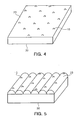
- FIGS. 4 to 6 show optical films according to one exemplary embodiment of the present invention.
- the optical films according to one exemplary embodiment of the present invention will be described in more detail with reference to FIGS. 4 to 6 .
- the optical film according to one exemplary embodiment of the present invention includes a light-incident portion 30 and a light exit portion 20, both of which may have a flat surface.
- a plurality of protrusions 10 are formed on at least one of the light-incident portion 30 and the light exit portion 20.
- a plurality of the protrusions 10 is formed so that they can satisfy the requirements of the Equations 1 and 2.
- the protrusions act as a spacer between optical films, thereby preventing the blocking between films.
- the protrusions are formed too compactly, hazes are getting serious, and a light-collimating effect is degraded by the spreading effect observed in the protrusions.
- the distance between the protrusions is too wide, the blocking between films is poor. Therefore, in accordance with the present invention, it is possible to effectively prevent the blocking between films and suppress the loss in brightness and the increases in haze by controlling the height and distance of the protrusions to the ranges of the Equations 1 and 2.
- the optical film according to one exemplary embodiment of the present invention may include a light exit portion 20 composed of a lens structure 25; and a flat light-incident portion 30, as shown in FIG. 5 .
- a plurality of protrusions 10 is formed on the lens structure 25.
- a plurality of the protrusions 10 is preferably formed around the peak of the lens structure 20.
- a plurality of protrusions 10 may also be formed on the light-incident portion 30 of the optical film.
- FIG. 5 shows that protrusions 10 are formed on respective lens structures 25, but the distribution of the protrusions may be varied according to the height of the formed protrusions, the desired optical performance and etc.
- the protrusions should be formed so that they can satisfy the requirements of the Equations 1 and 2, but it is not necessary to form protrusions on all the lens structures.
- the protrusions 10 when the protrusions 10 are formed around the peak of the lens structure 25 and/or the light-incident portion 30, the protrusions act as a spacer, and have the effect of preventing the blocking between films and the surface defects caused by the wet-out or Newton ring phenomenon.
- FIG. 5 shows that the lens structure 20 is a lenticular lens, but the present invention is not particularly limited thereto. Therefore, it is considered that the lens structure 20 comprises a variety of lens structures that are used in the art to collimate light, for example a prism, a lenticular lens, a micro lens array, a Fresnel lens, etc.
- the optical film according to one exemplary embodiment of the present invention may further comprise lens-shaped convex portions 40 in addition to the protrusions 10 formed on the lens structure 25.
- the convex portions 40 are preferably formed on the valley region of the lens structure.
- the convex portions 40 function to prevent the Moire phenomenon by reducing the transmission of light between the peak region and the valley region of the lens structure.
- the optical film according to one exemplary embodiment of the present invention includes: etching shapes of protrusions in at least one of a first mold and a second mold by using a laser beam, the first mold engraved with a shape of a light-incident portion and the second mold engraved with a shape of a light exit portion; and injecting a curable resin between the first mold and the second mold and curing the curable resin.
- a first mold engraved with a shape of a light-incident portion and/or a second mold engraved with a shape of a light exit portion are prepared, respectively.
- shapes of the light-incident portion and/or the light exit portion may be flat, or formed in the form of a lens structure. Molds having the shapes may be obtained by one on the conventional mold manufacturing methods widely known in the art, for example, mechanical cutting, photoresist reflow, bead coating, laser etching methods, etc.
- the mold may be a flat-type mold, a caterpillar-type mold or a drum-type mold, and may be formed of hard materials including metals such as nickel and chromium and ceramic, or soft materials such as polymers, silica-coated polymer films.
- shapes of the protrusions are etched by irradiating the first mold and/or the second mold with a laser beam (see FIG. 7 ).
- a laser beam to form the protrusions.
- the protrusions are preferably formed so that they can satisfy the requirements of Equations 1 and 2. That is, the protrusions are preferably formed so that they can satisfy the requirements of the following Equation: 80 ⁇ H 1/3 ⁇ P ⁇ 200 ⁇ H 1/3 and 0.1 ⁇ D ⁇ H ⁇ D, provided that a mean diameter of protrusions is represented by 'D', a mean height of protrusions is represented by 'H', and a mean distance between adjacent protrusions is represented by 'P'.
- an initial phase of a laser beam along a transverse direction of an optical film so as to form the protrusions.
- the optical defects caused by the regularity of the lens structure may be reduced without degrading the brightness of the optical film by changing the initial phase of the laser beam in a transverse direction of the optical film.
- the optical film according to one exemplary embodiment of the present invention may further comprise: engraving shapes of the convex portions prior to the formations of the protrusions.
- the operation of engraving shapes of the convex portions may be carried out through the same laser etching as in the formation of the protrusions, or carried out through the bead sanding.
- the Moire phenomenon may be improved by forming the convex portions on a valley region of the lens structure.
- the bead sanding has a problem in that it is impossible to control a position where the protrusions are formed.
- the bead sanding has the same effect as the laser etching since beads are mainly sanded on a convex region (i.e. a valley region of the lens structure in the optical film) of a mold rather than a concave region (i.e. a peak region of the lens structure in the optical film) of the mold due to the air turbulence during the bead sanding.
- the shapes of the protrusions are etched onto the first mold and/or the second mold using the above-mentioned process and then an optical film is prepared by injecting a curable resin between the first mold and the second mold and curing the curable resin.
- the optical film according to one exemplary embodiment of the present invention may be manufactured by extruding a UV curable resin and the like into a film, forming a desired pattern in a light exit portion and a light-incident portion of an optical film by passing through the film between the first mold and the second mold, and curing the film having a pattern formed therein by exposing the film to ultraviolet rays.
- the first mold and/or the second mold having the protrusions etched by laser beam according to the present invention, may be used as the molds to manufacture the optical film according to one exemplary embodiment of the present invention.
- Examples 1 and 2 and Comparative example 1 were conducted by stacking two lenticular lens sheets, which have been recently proven to be the most effectively used in televisions or other monitors, above and below.
- the elongation direction of lenticular lenses of the upper sheet is perpendicular to that of lenticular lenses of the lower sheet.
- films which include a flat light-incident portion and a light exit portion having a lenticular lens structure (pitch: 50 ⁇ m and height: 23 ⁇ m) formed therein, wherein protrusions having a diameter of 15 ⁇ m and a height of 5 ⁇ m are formed with a distance of 300 ⁇ m on a peak region of the lenticular lens structure, were used.
- a film which include a flat light-incident portion and a light exit portion having a lenticular lens structure (pitch: 50 ⁇ m and height: 23 ⁇ m) formed therein, wherein protrusions are not formed on the lenticular lens structure, was used.
- a film which include a flat light-incident portion and a light exit portion having a lenticular lens structure (pitch: 50 ⁇ m and height: 23 ⁇ m) formed therein, wherein protrusions having a diameter of 15 ⁇ m and a height of 5 ⁇ m are formed with a distance of 300 ⁇ m on a peak region of the lenticular lens structure, was used.
- films which include a flat light-incident portion and a light exit portion having a lenticular lens structure (pitch: 50 ⁇ m and height: 23 ⁇ m) formed therein, were used.
- protrusions are not formed on the lenticular lens sheets.
- the optical films of Examples 1 and 2 and Comparative example 1 were measured for brightness.
- Two lenticular lens sheets were put on a backlight diffuser plate, and the brightness of the lenticular lens sheets was measured using a brightness/optical distribution measurement machine (ELDIM), and re-measured and corrected using BM7 so as to measure the brightness of an optical film more exactly.
- ELDIM brightness/optical distribution measurement machine
- the measurement results of the optical film of Example 1 are shown in FIG. 8
- the measurement results of the optical film of Example 2 are shown in FIG. 9
- the measurement results of the optical film of Comparative example 1 are shown in FIG. 10 .
- the optical films of Examples 1 and 2 has the substantially same brightness value as the optical film of Comparative example 1 in which protrusions are not formed, which indicates that the loss in brightness is not caused by the protrusions.
- a PET film was stacked on the optical film, which include a flat light-incident portion and a light exit portion having a lenticular lens structure (pitch: 50 ⁇ m and height: 23 ⁇ m) formed therein, wherein protrusions having a diameter of 15 ⁇ m and a height of 5 ⁇ m are formed with a distance of 300 ⁇ m on a peak region of the lenticular lens structure, and the resulting was kept at 80°C for 48 hours under relative moisture of 95%, and then measured for the blocking between films, a wet-out phenomenon, a Newton ring phenomenon, and the presence of scratches.
- lenticular lens structure pitch: 50 ⁇ m and height: 23 ⁇ m
- a PET film was stacked on a brightness enhancement film (BEF, 3M) that has been most widely used in the art, and the resulting was kept at 80°C for 48 hours under relative moisture of 95%, and then measured for the blocking between films, a wet-out phenomenon, a Newton ring phenomenon, and the presence of scratches.
- BEF brightness enhancement film
- optical defects such as the Newton ring and wet-out phenomena and the blocking between films were observed with the naked eye in a distance of approximately 30cm through the reflected light with illumination of 150 lumens (working environments in offices or laboratories).
- FIG. 13 is a photograph illustrating the blocking between both of the film-laminates.
- FIG. 13 C shows film-laminate of Example 3
- FIG. 13 D shows film-laminate of Comparative example 2.
- Table 2 [Table 2]
- the optical film according to one exemplary embodiment of the present invention has the effect of preventing the blocking between films, compared to the conventional films, and also has the excellent effect of suppressing the formation of optical defects such as Moire, wet-out phenomena and Newton ring phenomena.
Landscapes
- Physics & Mathematics (AREA)
- General Physics & Mathematics (AREA)
- Optics & Photonics (AREA)
- Nonlinear Science (AREA)
- Mathematical Physics (AREA)
- Chemical & Material Sciences (AREA)
- Crystallography & Structural Chemistry (AREA)
- Optical Elements Other Than Lenses (AREA)
Description
- The present invention relates to a molded optical film for backlight units or illuminators and a manufacturing process thereof, and more particularly, to a molded optical film comprising a plurality of protrusions that is formed on one or both sides thereof and satisfy certain requirements and a manufacturing process thereof.
- As one of the fields to which the present invention is applicable, a liquid crystal display (LCD) is a device that generally displays an image by injecting a liquid crystal material between an upper substrate and a lower substrate, changing orientations of liquid crystal molecules by applying different electric potentials to pixel electrodes and common electrodes to form an electric field, and adjusting the transmissivity of light according to the orientations of the liquid crystal molecules, wherein the upper substrate has common electrodes, color filters and the like formed therein, and the lower substrate has thin film transistors, pixel electrodes and the like formed therein.
- Since a liquid crystal display panel is a passive element that does not voluntarily emit light, a backlight unit is necessarily installed in the liquid crystal display panel to supply light. In general, the backlight unit includes a light source supplying light; a diffuser plate or a light guide plate converting a line light source or a point light source into a surface light source; and a variety of optical films used to improve optical performances.
- The optical films used in the backlight unit includes a collimating film used to improve brightness, a diffusing film having an effect to shield defects of the backlight rear or bright lines of the light source, etc.
- Meanwhile, the collimating film has a lens structure arranged periodically to deflect a light path at one surface thereof. A generally used lens structure includes a prismatic lens, a semicylinderical lenticular lens, micro lens array, a Fresnel lens, etc.
- These lens structures have functions to collimate light emitted from a light source towards the front of a display to improve brightness. However, the collimating films having these lens structures have problems regarding the Moire phenomenon emerging from the periodicity, the wet-out phenomenon caused by the lack of gap, the Newton ring phenomenon of contour patterns due to the changes in air gap between two adjacent films, and also has a disadvantage in that surface defects occurs on a screen due to the above-mentioned phenomena.
- Therefore, in order to solve the above problems, there have been attempts to relieve the regularity of a lens structure such as prism or lenticular lens. As one representative example, there has been proposed a method for relieving the regularity of a lens structure by forming a shape of a lens structure in a mold using bite processing, throwing beads having a size of several micrometers to several tens micrometers to the mold, and sanding the lens structures to form a random secondary structure on the lens structure formed in the mold.
- However, this method has problems in that it is difficult to expect a position where a secondary structure is formed due to the difficulty in controlling a position where beads are thrown, and optical performances are deteriorated since beads are hardly thrown to a concave surface of the mold due to the air turbulence, but sanded mainly on a convex surface of the mold. Also, the reliability of products is degraded since the reproducibility is not maintained at every sanding process. Furthermore, optical films prepared in these methods show somewhat improved Moire or Newton ring phenomena, but have problems in that a collimating effect of the lens structures is deteriorated and the haze is increased due to the random formation of secondary structures.
- Meanwhile, backlight units including a film-laminate, which is prepared by stacking a plurality of films such as a collimating film, a diffusing film, a protective film and etc., has been recently used. These backlight units have problems in that surface defects are induced as the stacked films adhere (block) to each other.
FIG. 1 shows a wet-out phenomenon and a blocking phenomenon, caused when a protective film is stacked on a condenser film. However, the conventional methods have a problem in that it is difficult to prevent this blocking phenomenon. -
US 2007 253 064 A1 discloses an anti-glare light diffusing member having an anti-glare light diffusing layer including a binder matrix and particles on a transparent base material. -
WO 00/48037 A2 - JPH0921907A discloses prevention of the occurrence of Newton rings by arraying and arranging prisms on a structural surface and forming plural projecting part at a prescribed height and intervals on the rear surface.
- The present invention is designed to solve the problems of the prior art, and therefore it is an object of the present invention to provide an optical film capable of showing excellent performances of preventing blocking between films and enormously suppressing the formation of surface defects, which are caused by the Moire, Newton ring and wet-out phenomena, without degrading the brightness of the optical film.
- It is another object of the present invention to provide a process for manufacturing the optical film.
- The problem has been solved by the molded optical film and the process for manufacturing the same according to the independent claims. Preferred embodiment result from the sub claims.
- According to an aspect of the present invention, there is provided a molded optical film comprising a light-incident portion and a light exit portion, comprising a plurality of protrusions formed on at least one of the light-incident portion and the light exit portion, wherein a plurality of the protrusions satisfies the requirements of the following Equation: 80×H1/3 ≤P≤200×H1/3 and 0.1×D≤ H ≤ D, provided that a mean diameter of protrusions is represented by 'D', a mean height of protrusions is represented by 'H', and a mean distance between adjacent protrusions is represented by 'P'.
- In this case, each of a plurality of the protrusions has a mean height of 4.5 to 7µm, and a mean distance between the adjacent protrusions may be in a range of 150 to 300µm.
- Also, the sum of areas where a plurality of the protrusions is formed accounts for 0.5% to 5% of the entire area of one surface of the optical film.
- In addition, a plurality of the protrusions may be formed through laser etching.
- Additionally, the optical film according to one exemplary embodiment of the present invention may further comprise a plurality of lens-shaped convex portions. In this case, each of the convex portions may be formed through bead sanding or laser etching.
- The light exit portion is composed of a plurality of lens structures to collimate or spread light, and a plurality of the protrusions is formed on the lens structures.
- In this case, each of the lens structures may be one selected from the group consisting of a lenticular lens, a prism lens, a micro lens array and a Fresnel lens.
- Also, the optical film may further comprise a plurality of lens-shaped convex portions, and the convex portions may be formed in valley regions of the lens structures.
- According to another aspect of the present invention, there is provided a process for manufacturing an optical film. Here, the process comprises: additionally processing shapes of protrusions in at least one of a first mold and a second mold by using a laser beam, the first mold engraved with a shape of having a depressed light-incident portion and the second mold engraved with a shape of having an embossed light exit portion; and injecting a curable resin between the first mold and the second mold and curing the curable resin.
- In this case, the shapes of the protrusions are made so that they can satisfy the requirements of the following Equation: 80×H1/3≤P≤200×H1/3 and 0.1×D≤H≤D, provided that a mean diameter of protrusions is represented by 'D', a mean height of protrusions is represented by 'H', and a mean distance between adjacent protrusions is represented by 'P'.
- Also, in the operation of etching shapes of protrusions, an initial phase of laser beam may be changed along a transverse direction of the optical film.
- In addition, the first mold and the second mold may be a flat-type mold, a caterpillar-type mold or a drum-type mold.
- Additionally, prior to etching shapes of protrusions in at least one of a first mold and a second mold by using a laser beam, the process may further comprise: engraving the shapes of the convex portions. In this case, the operation of engraving the shapes of the convex portions may be carried out through bead sanding or laser etching.
- Furthermore, the light exit portion is formed in the form of a lenticular lens, a prism, a micro lens array or a Fresnel lens.
- The optical film according to one exemplary embodiment of the present invention may be useful to enormously suppress the formation of surface defects, which are caused by the Moire, wet-out and Newton ring phenomena, without degrading the brightness by forming a plurality of protrusions, which satisfies the specific requirements, on a light-incident portion or a light exit portion thereof.
- Also, the optical film according to one exemplary embodiment of the present invention may be useful to prevent the blocking between films since a plurality of the protrusions act as spacers.
- Additionally, the optical film according to one exemplary embodiment of the present invention may be useful to prevent the Moire performance more effectively by forming lens-shaped convex portions on the light-incident portion or the light exit portion in addition to the protrusions.
- Meanwhile, the process for manufacturing an optical film according to one exemplary embodiment of the present invention may be useful to adjust a shape, an area and a depth of etching per pulse under the control of an optical system, thus to mark spots easily compared to the conventional machine/bite cutting process, since the protrusion are formed using a laser beam. Also, the process according to one exemplary embodiment of the present invention has an advantage of exactly predicting a position where protrusions are formed, unlike the process, such as bead sanding, that does not exactly predict a position where protrusions are formed.
- Also, laser etching has an advantage in that, although any stereoscopic shapes are present in a processed mold, secondary shapes having a constant depth from a curved surface may be provided for a mold since the laser beam reaches the surface and then begin to etch the surface.
- In addition, the laser etching has an advantage in that it is advantageous to suppress a Moire or wet-out phenomenon caused by the uniformity since shapes per pulse are not uniform in a flat surface, compared to the bite processing.
- Additionally, when the laser beam is Q-switching oscillation, it has an advantage in that one pattern processing per pulse is achieved since the laser beam has a high energy per pulse, and the spot processing time is short due to the high pulse frequency (10∼100kHz), compared to the bite processing.
- Furthermore, the process for manufacturing an optical film according to one exemplary embodiment of the present invention may be useful to prevent the Moire, Newton ring and wet-out phenomena, without degrading the brightness of the optical film by changing an initial phase of a laser beam along a transverse direction of the optical film so as to simultaneously realize the regularity and irregularity.
-
-
FIG. 1 is a photograph illustrating a wet-out phenomenon and a blocking phenomenon occurring on a conventional optical film. -
FIG. 2 is a graph illustrating the changes in brightness of an optical film according to the distribution of protrusions. -
FIG. 3 is a diagram illustrating the effect of preventing the Moire performance when convex portions are formed on the optical film. -
FIGS. 4 to 6 are diagrams illustrating optical films according to one exemplary embodiments of the present invention. -
FIG. 7 is a diagram illustrating a method for manufacturing a mold according to one exemplary embodiments of the present invention. -
FIG. 8 is a diagram illustrating the brightness of an optical film described in Example 1. -
FIG. 9 is a diagram illustrating the brightness of an optical film of Example 2. -
FIG. 10 is a diagram illustrating the brightness of an optical film of Comparative example 1. -
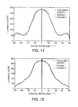
FIG. 11 is a graph illustrating the changes in brightness according to the vertical viewing angles of Examples 1 and 2 and Comparative example 1. -
FIG. 12 is a graph illustrating the changes in brightness according to the horizontal viewing angles of Examples 1 and 2 and Comparative example 1. -
FIG. 13 is a photograph illustrating the comparison of the blocking prevention effects between the optical films according to Examples 3 and Comparative example 2. - The present inventors have made ardent attempts, and fount that the formation of surface defects caused by the Moire, Newton ring and wet-out phenomena and the blocking between films may be significantly reduced without degrading the brightness of the optical film by forming a plurality of protrusions, whose height and distribution (distance) are controlled, on a surface of an optical film. Therefore, the present invention was completed on the basis of the above facts.
- The optical film according to one exemplary embodiments of the present invention includes a light-incident portion and a light exit portion and a plurality of protrusions is formed on at least one of the light-incident portion and the light exit portion.
- In this case, the light-incident portion refers to a surface that faces toward a light source. Here, light emitted from a light source enters the light-incident portion. And the light exit portion refers to a surface opposite to the light-incident portion. Here, the light passed through the optical film is emitted out from the light exit portion. Meanwhile, the light exit portion may have a lens structure to collimate light, that is, a lens structure such as a prism, a lenticular lens, a micro lens array, a Fresnel lens, etc.
- Meanwhile, in accordance with the present invention, a plurality of the protrusions may be formed on either or both the light-incident portion and the light exit portion.
- For the optical film according to one exemplary embodiment of the present invention, a plurality of the protrusions are formed so that they can satisfy the requirements of the following
Equations 

wherein, D represents a mean diameter of protrusions, H represents a mean height of protrusions, P represents a mean distance between adjacent protrusions, that is, a distance between peaks of adjacent protrusions. The unit of P, D and H is micrometer. - The conditions of
Equation 1 are set to ranges where the brightness of the optical film is not degraded, the surface defects caused by Moire, wet-out and Newton ring phenomena are reduced, and blocking between films is suppressed. Here, the blocking between films occurs when the mean distance P between the adjacent protrusions exceeds 200×H1/3. Also, when the mean distance P between the adjacent protrusions is less than 80×H1/3, hazes are getting serious. - Meanwhile, the conditions of
Equation 2 are associated with the formability of the protrusions. When the mean height of the protrusions is less than 1/10 of the mean diameter of the protrusions, it is impossible to suppress the blocking between films, whereas when the mean height of the protrusions exceeds the mean diameter of the protrusions, it is difficult to separate resin formed the protrusions from a mold in the manufacture of an optical film, which leads to the poor formability. - The mean diameter of the protrusions is determined in consideration of the relation with the pitch of the lens structure and the like, generally may be in a range of approximately 1 to 100 µm. For example, when the pitch of the lens structure is approximately 50µm, the mean diameter of the protrusions is preferably in a range of approximately 5 to 30µm, and most preferably approximately 15µm. In this case, the mean height of the protrusions is preferably in a range of approximately 1 to 30µm, and most preferably approximately 1.5 to 15µm. In collective consideration of the formability, optical performance and the like, the mean height of the protrusions is most preferably in a range of approximately 4.5 to 7µm. Meanwhile, the mean distance between the adjacent protrusions is preferably in a range of approximately 100 to 600µm, more preferably 100 to 400µm, most preferably 150 to 300µm.
- The blocking prevention effects and haze values according to the mean height of the protrusions and the mean distance between the protrusions are listed in the following Table 1.
- Protrusions are formed around peaks of lenticular lenses having a pitch of 50µm and a height of 23µm at conditions of height, diameter and distance as listed in Table 1, a PET film (SKC KOLON) having a thickness of 188µm is stacked on the lenticular lens. Then, the resulting is kept at 80°C for 48 hours under relative moisture of 95%, and measured for surface defects by the blocking between films and haze. A level of the surface defects is defined, as follows: X : surface defects formed, and ○ : No surface defect. And a level of haze is also defined, as follows: Good: 10% or less, and Poor: greater than 10%.
Table 1 [Table 1] Protrusion height H(µm) Protrusion diameter D(µm) Protrusion distance (µm), P 100 150 200 300 600 900 27 50 ○/Poor ○/Poor ○/Poor ○/Good ○/Good X/Good 16 30 ○/Poor ○/Poor ○/Poor ○/Good X/Good X/Good 9 20 ○/Poor ○/Poor ○/Good ○/Good X/Good X/Good 5 15 ○/Poor ○Good ○/Good ○/Good X/Good X/Good 1.5 11 ○/Good ○/Good ○/Good X/Good X/Good X/Good - As listed in Table 1, it was revealed that the optical film has excellent blocking prevention effect and haze value when the mean height H of protrusions and the mean distance P between protrusions are within the ranges satisfying the following Equation: 80×H1/3 ≤P≤200×H1/3.
- Meanwhile,
FIG. 2 is a graph illustrating the changes in brightness of an optical film according to the distribution of protrusions. InFIG. 2 , plotted are the brightness values of the optical film when protrusions having a diameter of 15 µm and a height of 5 µm are formed with different distances on a lenticular lens structure (pitch: 50 µm, and height: 23 µm). InFIG. 2 , Px represents a protrusion distance in a transverse direction of an optical film, and Py represents a protrusion distance in a longitudinal direction of an optical film. Meanwhile, the brightness values in the graph are expressed by relative brightness values on the assumption that a brightness value of a protrusion-free lenticular lens sheet is set to 100%. - Referring to
FIG. 2 , it was revealed that the brightness of the optical film is severely degraded when the distances Px and Py between protrusions are less than 50 µm. On the contrary, it was revealed that the relative brightness values are 99% or more when the distances Px and Py between protrusions exceed 100 µm. This indicates that the substantial loss in brightness caused by the formation of protrusions is reduced to 0 by adjusting the distribution of the protrusions. - The present inventors have made continuous attempts, and found that there is no substantial loss in brightness of the optical film when the sum of areas where protrusions are formed accounts for 0.5 to 5% of the entire surface area of one surface of the optical film.
- Therefore, for the optical film according to one exemplary embodiment of the present invention, the area where a plurality of the protrusions is formed is preferably in a range of 0.5 to 5% of the entire surface area of one surface of the optical film. When the area where the protrusions are formed exceeds 5%, the brightness of the optical film may be degraded, whereas the surface defects are slightly reduced when the area where the protrusions are formed is less than 0.5%. When the area where the protrusions are formed is within the range, the optical film according to one exemplary embodiment of the present invention has a substantially identical brightness, compared to the protrusion-free optical film.
- Meanwhile, the protrusions are preferably formed through laser etching. In accordance with the present invention, the reasons for the use of laser beam to form the protrusions are described, as follows.
- First, since the laser etching is a very precise process, the laser etching is suitable for forming a fine structure such as the protrusions according to one exemplary embodiment of the present invention. Also, the laser etching has an advantage in that, although any stereoscopic shapes such as the lens structure are present in a processed mold, secondary shapes having a constant depth from a curved surface may be provided with an etching surface since the laser beam reaches an etching surface and then begin to process the etching surface. Also, since a shape, an area and a depth of etching per pulse may be adjusted under the control of an optical system, it is possible to easily mark spots, and also to exactly form protrusions in a desired position. When the laser beam is used to form the protrusions as described above, it is possible to exactly control the position or height of the formed protrusions, unlike the conventional processes such as bead sanding. Therefore, the etching surface is simultaneously endowed with the regularity and irregularity by controlling the position or height of the protrusions. Therefore, it is possible to solve the problems such as the Moire and wet-out phenomena without any problems such as the loss in brightness that is caused when protrusions are randomly formed through the bead sanding.
- For example, during the laser etching for forming protrusions in according to the present invention, the protrusions are formed with constant distances along a longitudinal direction of an optical film and an etching surface is endowed with irregularity by changing an initial phase of laser beam along a transverse direction of the optical film. Therefore, it is possible to suppress surface defects, such as the Moire and wet-out phenomena, which are caused by the regularity of a lens structure, without the loss in brightness.
- Also, when a mold has no stereostructure such as a lens structure, shapes per pulse are not as much uniform as in the bite processing. Therefore, it is rather advantageous to suppress a Moire or wet-out phenomenon caused by the uniformity
- Meanwhile, the optical film according to one exemplary embodiment of the present invention may further comprise convex portions in addition to a plurality of the protrusions. The convex portions are formed to further improve optical performances of the optical film. Here, a width of each of the convex portions is preferably in a range of approximately 3 to 15µm, and a height of each convex portion is preferably in a range of approximately 1 to 3 µm. When the width of each convex portion is less than 3µm, the optical performance of the optical film is slightly improved, whereas the brightness of the optical film may be degraded when the width of each convex portion exceeds 15µm. Also, when the height of each convex portion is less than 1µm, the optical performance of the optical film is slightly improved, whereas the brightness of the optical film may be degraded when the height of each convex portion exceeds 10µm.
- Meanwhile, when a light exit portion of the optical film is composed of a lens structure, the convex portions are preferably formed on a valley region of the lens structure. When the convex portions are formed on the valley region of the lens structure, it is effective to prevent the Moire performance. One of major factors that cause a Moire phenomenon is the difference in transmission between a peak region and a valley region of the lens structure. In general, since the valley region of the lens structure is formed in the form of a cusp, the light incident towards the valley region has a higher reflection than the transmission of the incident light. As a result, the valley region of the lens structure has a relatively lower brightness than the crest region, which leads to the irregular striped stains caused by the Moire phenomenon. However, when lens-shaped convex portions are formed on the valley region of the lens structure according to the present invention, the transmission in the valley region is improved, thereby improving the Moire performance more effectively.
-
FIG. 3 shows photograph taken from a surface of a backlight unit (A) including a film having convex portions formed in the valley region of the lens structure, and a surface of a backlight unit (B) including a convex portion-free film. - As shown in
FIG. 3 , it might be revealed that light stripes are observed in the case of the convex portion-free film, but the film having convex portions has no stripe at all. -
FIGS. 4 to 6 show optical films according to one exemplary embodiment of the present invention. Hereinafter, the optical films according to one exemplary embodiment of the present invention will be described in more detail with reference toFIGS. 4 to 6 . - As shown in
FIG. 4 , the optical film according to one exemplary embodiment of the present invention includes a light-incident portion 30 and alight exit portion 20, both of which may have a flat surface. Here, a plurality ofprotrusions 10 are formed on at least one of the light-incident portion 30 and thelight exit portion 20. In this case, a plurality of theprotrusions 10 is formed so that they can satisfy the requirements of theEquations - When both of the light-
incident portion 30 and thelight exit portion 20 are flat, the surface defects, which are caused by the Moire, Newton ring and wet-out phenomena caused by the lens structure, do not occur, but the surface defects caused by the blocking between optical films occur. When the protrusions are formed on the light-incident portion and/or the light exit portion according to the present invention, the protrusions act as a spacer between optical films, thereby preventing the blocking between films. However, when the protrusions are formed too compactly, hazes are getting serious, and a light-collimating effect is degraded by the spreading effect observed in the protrusions. Also, when the distance between the protrusions is too wide, the blocking between films is poor. Therefore, in accordance with the present invention, it is possible to effectively prevent the blocking between films and suppress the loss in brightness and the increases in haze by controlling the height and distance of the protrusions to the ranges of theEquations - Meanwhile, the optical film according to one exemplary embodiment of the present invention may include a
light exit portion 20 composed of alens structure 25; and a flat light-incident portion 30, as shown inFIG. 5 . In this case, a plurality ofprotrusions 10 is formed on thelens structure 25. In particular, a plurality of theprotrusions 10 is preferably formed around the peak of thelens structure 20. Also, although not shown, a plurality ofprotrusions 10 may also be formed on the light-incident portion 30 of the optical film. -
FIG. 5 shows that protrusions 10 are formed onrespective lens structures 25, but the distribution of the protrusions may be varied according to the height of the formed protrusions, the desired optical performance and etc. Here, the protrusions should be formed so that they can satisfy the requirements of theEquations - In accordance with the present invention, when the
protrusions 10 are formed around the peak of thelens structure 25 and/or the light-incident portion 30, the protrusions act as a spacer, and have the effect of preventing the blocking between films and the surface defects caused by the wet-out or Newton ring phenomenon. -
FIG. 5 shows that thelens structure 20 is a lenticular lens, but the present invention is not particularly limited thereto. Therefore, it is considered that thelens structure 20 comprises a variety of lens structures that are used in the art to collimate light, for example a prism, a lenticular lens, a micro lens array, a Fresnel lens, etc. - As shown in
FIG. 6 , the optical film according to one exemplary embodiment of the present invention may further comprise lens-shapedconvex portions 40 in addition to theprotrusions 10 formed on thelens structure 25. Theconvex portions 40 are preferably formed on the valley region of the lens structure. When theconvex portions 40 are formed on the valley region of thelens structure 25, theconvex portions 40 function to prevent the Moire phenomenon by reducing the transmission of light between the peak region and the valley region of the lens structure. - Next, the process for manufacturing an optical film will be described in more detail.
- The optical film according to one exemplary embodiment of the present invention includes: etching shapes of protrusions in at least one of a first mold and a second mold by using a laser beam, the first mold engraved with a shape of a light-incident portion and the second mold engraved with a shape of a light exit portion; and injecting a curable resin between the first mold and the second mold and curing the curable resin.
- First, a first mold engraved with a shape of a light-incident portion and/or a second mold engraved with a shape of a light exit portion are prepared, respectively.
- In this case, shapes of the light-incident portion and/or the light exit portion may be flat, or formed in the form of a lens structure. Molds having the shapes may be obtained by one on the conventional mold manufacturing methods widely known in the art, for example, mechanical cutting, photoresist reflow, bead coating, laser etching methods, etc.
- In this case, the mold may be a flat-type mold, a caterpillar-type mold or a drum-type mold, and may be formed of hard materials including metals such as nickel and chromium and ceramic, or soft materials such as polymers, silica-coated polymer films.
- Next, shapes of the protrusions are etched by irradiating the first mold and/or the second mold with a laser beam (see
FIG. 7 ). For the present invention, the reasons for the use of laser beam to form the protrusions are described in the same manner as described above. - In this case, the protrusions are preferably formed so that they can satisfy the requirements of
Equations - Also, it is preferred to change an initial phase of a laser beam along a transverse direction of an optical film so as to form the protrusions. The optical defects caused by the regularity of the lens structure may be reduced without degrading the brightness of the optical film by changing the initial phase of the laser beam in a transverse direction of the optical film.
- Meanwhile, the optical film according to one exemplary embodiment of the present invention may further comprise: engraving shapes of the convex portions prior to the formations of the protrusions. In this case, the operation of engraving shapes of the convex portions may be carried out through the same laser etching as in the formation of the protrusions, or carried out through the bead sanding.
- When the convex portions are engraved through the laser etching, the Moire phenomenon may be improved by forming the convex portions on a valley region of the lens structure. Meanwhile, unlike the laser etching, the bead sanding has a problem in that it is impossible to control a position where the protrusions are formed. However, the bead sanding has the same effect as the laser etching since beads are mainly sanded on a convex region (i.e. a valley region of the lens structure in the optical film) of a mold rather than a concave region (i.e. a peak region of the lens structure in the optical film) of the mold due to the air turbulence during the bead sanding.
- The shapes of the protrusions are etched onto the first mold and/or the second mold using the above-mentioned process and then an optical film is prepared by injecting a curable resin between the first mold and the second mold and curing the curable resin.
- The process for manufacturing an optical film using a mold has been widely known in the art, and thus a skilled-person in this art may be used to manufacture the optical film according to one exemplary embodiment of the present invention without any difficulties, with reference to the specification of the present invention or the prior art.
- For example, the optical film according to one exemplary embodiment of the present invention may be manufactured by extruding a UV curable resin and the like into a film, forming a desired pattern in a light exit portion and a light-incident portion of an optical film by passing through the film between the first mold and the second mold, and curing the film having a pattern formed therein by exposing the film to ultraviolet rays.
- In this case, the first mold and/or the second mold, having the protrusions etched by laser beam according to the present invention, may be used as the molds to manufacture the optical film according to one exemplary embodiment of the present invention.
- Hereinafter, exemplary embodiments of the present invention are described in more detail.
- The following Examples 1 and 2 and Comparative example 1 were conducted by stacking two lenticular lens sheets, which have been recently proven to be the most effectively used in televisions or other monitors, above and below. In this case, the elongation direction of lenticular lenses of the upper sheet is perpendicular to that of lenticular lenses of the lower sheet.
- As the two lenticular lens sheets, films, which include a flat light-incident portion and a light exit portion having a lenticular lens structure (pitch: 50µm and height: 23µm) formed therein, wherein protrusions having a diameter of 15µm and a height of 5µm are formed with a distance of 300µm on a peak region of the lenticular lens structure, were used.
- As the lower lenticular lens sheet, a film, which include a flat light-incident portion and a light exit portion having a lenticular lens structure (pitch: 50µm and height: 23µm) formed therein, wherein protrusions are not formed on the lenticular lens structure, was used. As the upper lenticular lens sheet, a film, which include a flat light-incident portion and a light exit portion having a lenticular lens structure (pitch: 50µm and height: 23µm) formed therein, wherein protrusions having a diameter of 15µm and a height of 5µm are formed with a distance of 300µm on a peak region of the lenticular lens structure, was used.
- As the two lenticular lens sheets, films, which include a flat light-incident portion and a light exit portion having a lenticular lens structure (pitch: 50µm and height: 23µm) formed therein, were used. Here, protrusions are not formed on the lenticular lens sheets.
- The optical films of Examples 1 and 2 and Comparative example 1 were measured for brightness. Two lenticular lens sheets were put on a backlight diffuser plate, and the brightness of the lenticular lens sheets was measured using a brightness/optical distribution measurement machine (ELDIM), and re-measured and corrected using BM7 so as to measure the brightness of an optical film more exactly.
- The measurement results of the optical film of Example 1 are shown in
FIG. 8 , the measurement results of the optical film of Example 2 are shown inFIG. 9 , and the measurement results of the optical film of Comparative example 1 are shown inFIG. 10 . - Also, the brightness values according to the vertical/horizontal viewing angles of the optical films of Examples 1 and 2 and Comparative examples are shown in
FIGS. 11 and 12 , respectively. - As shown in
FIGS. 8 to 12 , it was revealed that the optical films of Examples 1 and 2 has the substantially same brightness value as the optical film of Comparative example 1 in which protrusions are not formed, which indicates that the loss in brightness is not caused by the protrusions. - A PET film was stacked on the optical film, which include a flat light-incident portion and a light exit portion having a lenticular lens structure (pitch: 50µm and height: 23µm) formed therein, wherein protrusions having a diameter of 15µm and a height of 5µm are formed with a distance of 300µm on a peak region of the lenticular lens structure, and the resulting was kept at 80°C for 48 hours under relative moisture of 95%, and then measured for the blocking between films, a wet-out phenomenon, a Newton ring phenomenon, and the presence of scratches.
- In comparison, a PET film was stacked on a brightness enhancement film (BEF, 3M) that has been most widely used in the art, and the resulting was kept at 80°C for 48 hours under relative moisture of 95%, and then measured for the blocking between films, a wet-out phenomenon, a Newton ring phenomenon, and the presence of scratches.
- The optical defects such as the Newton ring and wet-out phenomena and the blocking between films were observed with the naked eye in a distance of approximately 30cm through the reflected light with illumination of 150 lumens (working environments in offices or laboratories).
- Meanwhile, the presence of scratches was measured using a pencil hardness tester, and observed with the naked eye after the 2H test.
- The measurement results are listed in the following Table 2, and
FIG. 13 is a photograph illustrating the blocking between both of the film-laminates. Here,FIG. 13 C shows film-laminate of Example 3 andFIG. 13 D shows film-laminate of Comparative example 2.Table 2 [Table 2] Example 3 Comparative example 2 Newton ring None Detected Wet-out None Detected Blocking between films None Detected Scratches(2H test) None (Level 5H) Detected (Level 1H) - As listed in Table 2 and shown in
FIG. 13 , it was revealed that the optical film according to one exemplary embodiment of the present invention has the effect of preventing the blocking between films, compared to the conventional films, and also has the excellent effect of suppressing the formation of optical defects such as Moire, wet-out phenomena and Newton ring phenomena.
Claims (9)
- A molded optical film comprising a light-incident portion (30) and a light exit portion (20) and wherein the molded optical film is arranged such that light entering the light-incident portion (30) passes through the molded optical film and is then emitted from the light exit portion (20), wherein the light exit portion (20) is composed of a plurality of lens structures (25) to collimate or spread light, and a plurality of the protrusions (10) are formed around the peaks of the lens structures (25) such that the protrusions act as spacers when a further optical film is placed adjacent to the molded optical film, and wherein the plurality of the protrusions (10) satisfies the requirements of the following Equations: 80 (H[µm])1/3 ≤ P[µm] ≤ 2x10² (H[µm])1/3 and 1x10⁻¹·D[µm] ≤ H[µm] ≤ D[µm], provided that a mean diameter of the plurality of protrusions (10) is represented by 'D,' a mean height of the plurality of protrusions (10) is represented by 'H,' and a mean distance between the adjacent protrusions is represented by 'P', characterized in that each of the plurality of the protrusions (10) has a mean height of 4.5 to 7 µm, and a mean distance between the adjacent protrusions (10) is in a range of 150 to 300 µm.
- The molded optical film of claim 1, wherein an area of the molded optical film having a plurality of the protrusions (10) formed therein accounts for 0.5% to 5% of the entire surface area of one surface of the molded optical film.
- The molded optical film of claim 1, further comprising a plurality of lens-shaped convex portions (40).
- The molded optical film of claim 1, wherein each of the lens structures (25) is made of one selected from the group consisting of a lenticular lens, a prism lens, a micro lens array and a fresnel lens.
- The molded optical film of claim 1, wherein the molded optical film further comprises a plurality of lens-shaped convex portions (40), and the convex portions (40) are formed in valley regions of the lens structures (25).
- A process for manufacturing a molded optical film according to claim 1, comprising:additionally processing shapes of protrusions in at least one of a first mold and a second mold by using a laser beam, the first mold having a depressed light-incident portion and the second mold having an embossed light exit portion, wherein the light exit portion is formed in the form of a lenticular lens, a prism or a micro lens array of a Fresnel lens; andinjecting a curable resin between the first mold and the second mold and curing the curable resin.
- The process of claim 6, wherein, in the operation of additionally processing shapes of protrusions, an initial phase of laser beam is changed along a transverse direction of the molded optical film.
- The process of claim 6, further comprising: engraving the shapes of the convex portions prior to additionally processing shapes of protrusions in at least one of a first mold and a second mold by using a laser beam.
- The process of claim 8, wherein the operation of engraving the shapes of the convex portions is carried out through bead sanding or laser processing.
Applications Claiming Priority (3)
| Application Number | Priority Date | Filing Date | Title |
|---|---|---|---|
| KR20080019811 | 2008-03-03 | ||
| PCT/KR2009/001048 WO2009110736A2 (en) | 2008-03-03 | 2009-03-03 | Optical film and manufacturing process thereof |
| KR1020090018176A KR100988463B1 (en) | 2008-03-03 | 2009-03-03 | optical film and manufacturing process thereof |
Publications (3)
| Publication Number | Publication Date |
|---|---|
| EP2247967A2 EP2247967A2 (en) | 2010-11-10 |
| EP2247967A4 EP2247967A4 (en) | 2011-08-10 |
| EP2247967B1 true EP2247967B1 (en) | 2015-07-29 |
Family
ID=41295148
Family Applications (1)
| Application Number | Title | Priority Date | Filing Date |
|---|---|---|---|
| EP09718109.3A Active EP2247967B1 (en) | 2008-03-03 | 2009-03-03 | Optical film and manufacturing process thereof |
Country Status (6)
| Country | Link |
|---|---|
| US (1) | US8134781B2 (en) |
| EP (1) | EP2247967B1 (en) |
| JP (1) | JP5579082B2 (en) |
| KR (1) | KR100988463B1 (en) |
| CN (1) | CN101918867B (en) |
| WO (1) | WO2009110736A2 (en) |
Families Citing this family (18)
| Publication number | Priority date | Publication date | Assignee | Title |
|---|---|---|---|---|
| JPS6358322A (en) * | 1986-08-29 | 1988-03-14 | Canon Inc | Control system for light transmissivity |
| KR101840482B1 (en) * | 2009-12-30 | 2018-03-20 | 쓰리엠 이노베이티브 프로퍼티즈 컴파니 | Light directing composite film for energy efficient sign |
| WO2011129587A2 (en) * | 2010-04-13 | 2011-10-20 | 주식회사 엘지화학 | Light-condensing film having superior anti-adhesion performance and superior moiré prevention effects, backlight unit comprising same, and display device comprising the backlight unit |
| KR101214648B1 (en) * | 2010-04-13 | 2012-12-24 | 주식회사 엘지화학 | Condensing film having excellent prevention property of blocking and moire, backlight unit and display device comprising the same |
| WO2012018707A1 (en) * | 2010-08-02 | 2012-02-09 | 3M Innovative Properties Company | Uniform light directing film and method of making same |
| CN102436021B (en) * | 2011-12-21 | 2014-10-22 | 北京康得新复合材料股份有限公司 | Prism-structure bright enhancement film with raised structures in non-uniform distribution |
| KR20130073004A (en) * | 2011-12-22 | 2013-07-02 | 제일모직주식회사 | Optical film, back light unit comprising the same and liquid crystal display comprising the same |
| US9346710B2 (en) * | 2012-05-29 | 2016-05-24 | Corning Incorporated | Sheet glass product fabrication with growth-limited glass bump spacers |
| JP2014056042A (en) * | 2012-09-11 | 2014-03-27 | Dainippon Printing Co Ltd | Optical sheet, surface light source device, transmissive display device, and production method of optical sheet |
| CN102878527A (en) * | 2012-09-14 | 2013-01-16 | 张家港康得新光电材料有限公司 | Light uniformizing film and illuminating equipment using light uniformizing film |
| KR101253557B1 (en) * | 2012-11-12 | 2013-04-11 | 신화인터텍 주식회사 | Complex optical film for a display, and light source assembly and liquid crystal display including the same |
| KR101901255B1 (en) | 2012-12-28 | 2018-09-21 | 엘지디스플레이 주식회사 | Display device |
| TWI527677B (en) * | 2013-08-01 | 2016-04-01 | Lg化學股份有限公司 | Alignment film for liquid crystal lens and mold for preparing the same |
| KR20150026167A (en) * | 2013-09-02 | 2015-03-11 | 인스콘테크(주) | Newton Ring Improved Laminated optical films and method of manufacturing the same |
| KR101532919B1 (en) * | 2013-12-31 | 2015-07-02 | 신화인터텍 주식회사 | Optical film and light source assemblyand Liquid Crystal Display including the same |
| JP6706878B2 (en) * | 2014-05-19 | 2020-06-10 | 株式会社きもと | Anti-newton ring film |
| CN109975988B (en) * | 2017-12-28 | 2021-12-17 | 上海仪电显示材料有限公司 | Bore hole 3D lenticular lens and 3D display screen module |
| US20210179487A1 (en) * | 2019-12-16 | 2021-06-17 | Samsung Display Co., Ltd. | Cover window and display device including the same |
Citations (2)
| Publication number | Priority date | Publication date | Assignee | Title |
|---|---|---|---|---|
| JPH0921907A (en) * | 1995-07-07 | 1997-01-21 | Shimura Kaken Kogyo Kk | Prism sheet and illumination device using the same |
| WO2000048037A2 (en) * | 1999-02-09 | 2000-08-17 | 3M Innovative Properties Company | Optical film with defect-reducing surface and method for making same |
Family Cites Families (19)
| Publication number | Priority date | Publication date | Assignee | Title |
|---|---|---|---|---|
| US4345308A (en) * | 1978-08-25 | 1982-08-17 | General Instrument Corporation | Alpha-numeric display array and method of manufacture |
| NL8801361A (en) * | 1988-05-27 | 1989-12-18 | Koninkl Philips Electronics Nv | VIEW PROJECTION SCREEN. |
| WO1995031737A1 (en) | 1994-05-18 | 1995-11-23 | Dai Nippon Printing Co., Ltd. | Glare-proof film |
| US6130777A (en) * | 1996-05-16 | 2000-10-10 | Dai Nippon Printing Co., Ltd. | Lenticular lens sheet with both a base sheet having lenticular elements and a surface diffusing part having elements of elementary shape smaller than lenticular elements |
| JPH09311204A (en) * | 1996-05-16 | 1997-12-02 | Dainippon Printing Co Ltd | Lenticular lens sheet and its production |
| US6124975A (en) * | 1998-09-18 | 2000-09-26 | U.S. Philips Corporation | Lenticular sheet |
| KR100432438B1 (en) * | 2001-01-18 | 2004-05-22 | 주식회사 송산 | Prism Diffuser |
| JP2003170445A (en) * | 2001-12-10 | 2003-06-17 | Nitto Denko Corp | Method for manufacturing optical film |
| JP4559882B2 (en) * | 2005-03-16 | 2010-10-13 | 大日本印刷株式会社 | Light converging sheet, surface light source device, transmissive display device |
| CN101292178B (en) * | 2005-10-17 | 2011-01-26 | 三菱丽阳株式会社 | Prism sheet and production method thereof and surface light source device |
| JP2007121605A (en) * | 2005-10-27 | 2007-05-17 | Konica Minolta Opto Inc | Antiglare film, manufacturing method of antiglare film, antiglare antireflection film, polarizing plate, and display apparatus |
| JP5011877B2 (en) | 2006-08-04 | 2012-08-29 | 凸版印刷株式会社 | Anti-glare light diffusing member and display having anti-glare light diffusing member |
| KR100697613B1 (en) * | 2006-06-22 | 2007-03-22 | 주식회사 엘지에스 | Optical film and planar lighting source apparatus using the same |
| KR100759690B1 (en) | 2006-07-04 | 2007-09-17 | 삼성에스디아이 주식회사 | Backlight unit of a liquid crystal display device and method for fabricating a light guided panel of the same |
| KR100806132B1 (en) | 2006-08-18 | 2008-02-22 | 신화인터텍 주식회사 | Diffuse sheet and backlight assembly and liquid crystal display comprising the same |
| JPWO2008020612A1 (en) * | 2006-08-18 | 2010-01-07 | 大日本印刷株式会社 | Optical laminate manufacturing method, manufacturing apparatus, optical laminate, polarizing plate, and image display device |
| KR100851558B1 (en) | 2006-08-29 | 2008-08-11 | 신화인터텍 주식회사 | Prism sheet and backlight assembly and liquid crystal display comprising the same |
| KR100841447B1 (en) * | 2007-11-06 | 2008-06-26 | 주식회사 엘지에스 | Optical film and lighting device having the same |
| JP5361007B2 (en) * | 2008-03-03 | 2013-12-04 | エルジー・ケム・リミテッド | Manufacturing method of mold for optical film manufacturing |
-
2009
- 2009-03-03 US US12/866,201 patent/US8134781B2/en active Active
- 2009-03-03 CN CN2009801018457A patent/CN101918867B/en active Active
- 2009-03-03 WO PCT/KR2009/001048 patent/WO2009110736A2/en active Application Filing
- 2009-03-03 JP JP2010547573A patent/JP5579082B2/en active Active
- 2009-03-03 EP EP09718109.3A patent/EP2247967B1/en active Active
- 2009-03-03 KR KR1020090018176A patent/KR100988463B1/en active IP Right Grant
Patent Citations (2)
| Publication number | Priority date | Publication date | Assignee | Title |
|---|---|---|---|---|
| JPH0921907A (en) * | 1995-07-07 | 1997-01-21 | Shimura Kaken Kogyo Kk | Prism sheet and illumination device using the same |
| WO2000048037A2 (en) * | 1999-02-09 | 2000-08-17 | 3M Innovative Properties Company | Optical film with defect-reducing surface and method for making same |
Also Published As
| Publication number | Publication date |
|---|---|
| JP2011513771A (en) | 2011-04-28 |
| KR20090094777A (en) | 2009-09-08 |
| CN101918867B (en) | 2012-10-24 |
| US20100321787A1 (en) | 2010-12-23 |
| JP5579082B2 (en) | 2014-08-27 |
| CN101918867A (en) | 2010-12-15 |
| KR100988463B1 (en) | 2010-10-20 |
| WO2009110736A2 (en) | 2009-09-11 |
| US8134781B2 (en) | 2012-03-13 |
| EP2247967A2 (en) | 2010-11-10 |
| WO2009110736A3 (en) | 2009-12-10 |
| EP2247967A4 (en) | 2011-08-10 |
Similar Documents
| Publication | Publication Date | Title |
|---|---|---|
| EP2247967B1 (en) | Optical film and manufacturing process thereof | |
| EP2247431B1 (en) | Process of making mold for optical film | |
| KR101002522B1 (en) | Optical film | |
| US20120134177A1 (en) | Light guide plate for surface light source device and backlight unit using the same | |
| KR20090015997A (en) | Surface light guide | |
| JP2009075266A (en) | Optical sheet | |
| KR100927513B1 (en) | Surface light source unit-use light guide and production method therefor and surface light source unit | |
| KR20090130430A (en) | Liquid crystal display device, area light source device, prism sheet and their manufacturing method | |
| KR20070106397A (en) | Optical film and back light unit having the same | |
| JP5741121B2 (en) | A mold for manufacturing an optical lens sheet for controlling an illumination optical path, the sheet manufactured using the mold, a method of manufacturing the sheet using the mold, a liquid crystal display device, and a display | |
| KR20140087417A (en) | Optical sheet and method for preparing the same | |
| JP5646728B2 (en) | Condensing film excellent in adhesion preventing performance and moire preventing effect, backlight unit including the same, display device, and manufacturing method of condensing film | |
| KR20230106379A (en) | Light guide plate with improved external visibility with complex pattern and display device including same | |
| KR20230013448A (en) | A light guide plate using a grouping pattern and a display device including the same | |
| JP3729429B2 (en) | Light guide for surface light source element and surface light source element | |
| KR102091260B1 (en) | Optical Sheet and Back Light Unit Comprising the Same | |
| KR101246701B1 (en) | Lenticular lens sheet having a improved moire and method for designing the same | |
| KR20110001301A (en) | Condensing type optical sheet | |
| KR20120134495A (en) | Microlens array sheet | |
| KR20130123260A (en) | Light guiding plate for surface light source device and back light unit with controllable viewing angle comprising the same | |
| KR20070056257A (en) | Prismatic film | |
| KR20120015891A (en) | Optical film having anti-scratch chracteristics for enhanced brightness and preparing thereof | |
| KR20140049821A (en) | Light guide for surface light source device, production method therefor and surface light source device | |
| KR20120012173A (en) | Optical film having Anti-scratch chracteristics for enhanced brightness and Preparing thereof |
Legal Events
| Date | Code | Title | Description |
|---|---|---|---|
| PUAI | Public reference made under article 153(3) epc to a published international application that has entered the european phase |
Free format text: ORIGINAL CODE: 0009012 |
|
| 17P | Request for examination filed |
Effective date: 20100623 |
|
| AK | Designated contracting states |
Kind code of ref document: A2 Designated state(s): AT BE BG CH CY CZ DE DK EE ES FI FR GB GR HR HU IE IS IT LI LT LU LV MC MK MT NL NO PL PT RO SE SI SK TR |
|
| AX | Request for extension of the european patent |
Extension state: AL BA RS |
|
| RIN1 | Information on inventor provided before grant (corrected) |
Inventor name: HAN, SANG-CHOLL Inventor name: PARK, KWANG-SEUNG Inventor name: KIM, JIN-HYUN Inventor name: JO, WON-YOUNG Inventor name: KIM, KYUNG-MO |
|
| DAX | Request for extension of the european patent (deleted) | ||
| A4 | Supplementary search report drawn up and despatched |
Effective date: 20110708 |
|
| RIC1 | Information provided on ipc code assigned before grant |
Ipc: G02F 1/1335 20060101ALI20110704BHEP Ipc: G02B 5/02 20060101ALI20110704BHEP Ipc: G02B 5/04 20060101AFI20110704BHEP |
|
| 17Q | First examination report despatched |
Effective date: 20120628 |
|
| RIC1 | Information provided on ipc code assigned before grant |
Ipc: G02B 3/00 20060101ALI20121212BHEP Ipc: G02F 1/1335 20060101ALI20121212BHEP Ipc: G02B 5/02 20060101ALI20121212BHEP Ipc: G02B 5/04 20060101AFI20121212BHEP |
|
| GRAP | Despatch of communication of intention to grant a patent |
Free format text: ORIGINAL CODE: EPIDOSNIGR1 |
|
| INTG | Intention to grant announced |
Effective date: 20150430 |
|
| GRAS | Grant fee paid |
Free format text: ORIGINAL CODE: EPIDOSNIGR3 |
|
| GRAA | (expected) grant |
Free format text: ORIGINAL CODE: 0009210 |
|
| AK | Designated contracting states |
Kind code of ref document: B1 Designated state(s): AT BE BG CH CY CZ DE DK EE ES FI FR GB GR HR HU IE IS IT LI LT LU LV MC MK MT NL NO PL PT RO SE SI SK TR |
|
| REG | Reference to a national code |
Ref country code: GB Ref legal event code: FG4D |
|
| REG | Reference to a national code |
Ref country code: CH Ref legal event code: EP |
|
| REG | Reference to a national code |
Ref country code: AT Ref legal event code: REF Ref document number: 739744 Country of ref document: AT Kind code of ref document: T Effective date: 20150815 |
|
| REG | Reference to a national code |
Ref country code: IE Ref legal event code: FG4D |
|
| REG | Reference to a national code |
Ref country code: DE Ref legal event code: R096 Ref document number: 602009032485 Country of ref document: DE |
|
| REG | Reference to a national code |
Ref country code: AT Ref legal event code: MK05 Ref document number: 739744 Country of ref document: AT Kind code of ref document: T Effective date: 20150729 |
|
| REG | Reference to a national code |
Ref country code: LT Ref legal event code: MG4D |
|
| REG | Reference to a national code |
Ref country code: NL Ref legal event code: MP Effective date: 20150729 |
|
| PG25 | Lapsed in a contracting state [announced via postgrant information from national office to epo] |
Ref country code: LV Free format text: LAPSE BECAUSE OF FAILURE TO SUBMIT A TRANSLATION OF THE DESCRIPTION OR TO PAY THE FEE WITHIN THE PRESCRIBED TIME-LIMIT Effective date: 20150729 Ref country code: NO Free format text: LAPSE BECAUSE OF FAILURE TO SUBMIT A TRANSLATION OF THE DESCRIPTION OR TO PAY THE FEE WITHIN THE PRESCRIBED TIME-LIMIT Effective date: 20151029 Ref country code: FI Free format text: LAPSE BECAUSE OF FAILURE TO SUBMIT A TRANSLATION OF THE DESCRIPTION OR TO PAY THE FEE WITHIN THE PRESCRIBED TIME-LIMIT Effective date: 20150729 Ref country code: LT Free format text: LAPSE BECAUSE OF FAILURE TO SUBMIT A TRANSLATION OF THE DESCRIPTION OR TO PAY THE FEE WITHIN THE PRESCRIBED TIME-LIMIT Effective date: 20150729 Ref country code: GR Free format text: LAPSE BECAUSE OF FAILURE TO SUBMIT A TRANSLATION OF THE DESCRIPTION OR TO PAY THE FEE WITHIN THE PRESCRIBED TIME-LIMIT Effective date: 20151030 |
|
| REG | Reference to a national code |
Ref country code: FR Ref legal event code: PLFP Year of fee payment: 8 |
|
| PG25 | Lapsed in a contracting state [announced via postgrant information from national office to epo] |
Ref country code: IS Free format text: LAPSE BECAUSE OF FAILURE TO SUBMIT A TRANSLATION OF THE DESCRIPTION OR TO PAY THE FEE WITHIN THE PRESCRIBED TIME-LIMIT Effective date: 20151129 Ref country code: PT Free format text: LAPSE BECAUSE OF FAILURE TO SUBMIT A TRANSLATION OF THE DESCRIPTION OR TO PAY THE FEE WITHIN THE PRESCRIBED TIME-LIMIT Effective date: 20151130 Ref country code: SE Free format text: LAPSE BECAUSE OF FAILURE TO SUBMIT A TRANSLATION OF THE DESCRIPTION OR TO PAY THE FEE WITHIN THE PRESCRIBED TIME-LIMIT Effective date: 20150729 Ref country code: PL Free format text: LAPSE BECAUSE OF FAILURE TO SUBMIT A TRANSLATION OF THE DESCRIPTION OR TO PAY THE FEE WITHIN THE PRESCRIBED TIME-LIMIT Effective date: 20150729 Ref country code: AT Free format text: LAPSE BECAUSE OF FAILURE TO SUBMIT A TRANSLATION OF THE DESCRIPTION OR TO PAY THE FEE WITHIN THE PRESCRIBED TIME-LIMIT Effective date: 20150729 Ref country code: ES Free format text: LAPSE BECAUSE OF FAILURE TO SUBMIT A TRANSLATION OF THE DESCRIPTION OR TO PAY THE FEE WITHIN THE PRESCRIBED TIME-LIMIT Effective date: 20150729 Ref country code: HR Free format text: LAPSE BECAUSE OF FAILURE TO SUBMIT A TRANSLATION OF THE DESCRIPTION OR TO PAY THE FEE WITHIN THE PRESCRIBED TIME-LIMIT Effective date: 20150729 |
|
| PG25 | Lapsed in a contracting state [announced via postgrant information from national office to epo] |
Ref country code: NL Free format text: LAPSE BECAUSE OF FAILURE TO SUBMIT A TRANSLATION OF THE DESCRIPTION OR TO PAY THE FEE WITHIN THE PRESCRIBED TIME-LIMIT Effective date: 20150729 |
|
| PG25 | Lapsed in a contracting state [announced via postgrant information from national office to epo] |
Ref country code: DK Free format text: LAPSE BECAUSE OF FAILURE TO SUBMIT A TRANSLATION OF THE DESCRIPTION OR TO PAY THE FEE WITHIN THE PRESCRIBED TIME-LIMIT Effective date: 20150729 Ref country code: EE Free format text: LAPSE BECAUSE OF FAILURE TO SUBMIT A TRANSLATION OF THE DESCRIPTION OR TO PAY THE FEE WITHIN THE PRESCRIBED TIME-LIMIT Effective date: 20150729 Ref country code: CZ Free format text: LAPSE BECAUSE OF FAILURE TO SUBMIT A TRANSLATION OF THE DESCRIPTION OR TO PAY THE FEE WITHIN THE PRESCRIBED TIME-LIMIT Effective date: 20150729 Ref country code: SK Free format text: LAPSE BECAUSE OF FAILURE TO SUBMIT A TRANSLATION OF THE DESCRIPTION OR TO PAY THE FEE WITHIN THE PRESCRIBED TIME-LIMIT Effective date: 20150729 Ref country code: IT Free format text: LAPSE BECAUSE OF FAILURE TO SUBMIT A TRANSLATION OF THE DESCRIPTION OR TO PAY THE FEE WITHIN THE PRESCRIBED TIME-LIMIT Effective date: 20150729 |
|
| REG | Reference to a national code |
Ref country code: DE Ref legal event code: R097 Ref document number: 602009032485 Country of ref document: DE |
|
| PG25 | Lapsed in a contracting state [announced via postgrant information from national office to epo] |
Ref country code: RO Free format text: LAPSE BECAUSE OF FAILURE TO SUBMIT A TRANSLATION OF THE DESCRIPTION OR TO PAY THE FEE WITHIN THE PRESCRIBED TIME-LIMIT Effective date: 20150729 |
|
| PLBE | No opposition filed within time limit |
Free format text: ORIGINAL CODE: 0009261 |
|
| STAA | Information on the status of an ep patent application or granted ep patent |
Free format text: STATUS: NO OPPOSITION FILED WITHIN TIME LIMIT |
|
| 26N | No opposition filed |
Effective date: 20160502 |
|
| PG25 | Lapsed in a contracting state [announced via postgrant information from national office to epo] |
Ref country code: BE Free format text: LAPSE BECAUSE OF NON-PAYMENT OF DUE FEES Effective date: 20160331 Ref country code: SI Free format text: LAPSE BECAUSE OF FAILURE TO SUBMIT A TRANSLATION OF THE DESCRIPTION OR TO PAY THE FEE WITHIN THE PRESCRIBED TIME-LIMIT Effective date: 20150729 |
|
| PG25 | Lapsed in a contracting state [announced via postgrant information from national office to epo] |
Ref country code: MC Free format text: LAPSE BECAUSE OF FAILURE TO SUBMIT A TRANSLATION OF THE DESCRIPTION OR TO PAY THE FEE WITHIN THE PRESCRIBED TIME-LIMIT Effective date: 20150729 Ref country code: LU Free format text: LAPSE BECAUSE OF FAILURE TO SUBMIT A TRANSLATION OF THE DESCRIPTION OR TO PAY THE FEE WITHIN THE PRESCRIBED TIME-LIMIT Effective date: 20160303 |
|
| REG | Reference to a national code |
Ref country code: CH Ref legal event code: PL |
|
| REG | Reference to a national code |
Ref country code: IE Ref legal event code: MM4A |
|
| PG25 | Lapsed in a contracting state [announced via postgrant information from national office to epo] |
Ref country code: BE Free format text: LAPSE BECAUSE OF FAILURE TO SUBMIT A TRANSLATION OF THE DESCRIPTION OR TO PAY THE FEE WITHIN THE PRESCRIBED TIME-LIMIT Effective date: 20150729 |
|
| PG25 | Lapsed in a contracting state [announced via postgrant information from national office to epo] |
Ref country code: IE Free format text: LAPSE BECAUSE OF NON-PAYMENT OF DUE FEES Effective date: 20160303 Ref country code: CH Free format text: LAPSE BECAUSE OF NON-PAYMENT OF DUE FEES Effective date: 20160331 Ref country code: LI Free format text: LAPSE BECAUSE OF NON-PAYMENT OF DUE FEES Effective date: 20160331 |
|
| REG | Reference to a national code |
Ref country code: FR Ref legal event code: PLFP Year of fee payment: 9 |
|
| PG25 | Lapsed in a contracting state [announced via postgrant information from national office to epo] |
Ref country code: MT Free format text: LAPSE BECAUSE OF FAILURE TO SUBMIT A TRANSLATION OF THE DESCRIPTION OR TO PAY THE FEE WITHIN THE PRESCRIBED TIME-LIMIT Effective date: 20150729 |
|
| REG | Reference to a national code |
Ref country code: FR Ref legal event code: PLFP Year of fee payment: 10 |
|
| PG25 | Lapsed in a contracting state [announced via postgrant information from national office to epo] |
Ref country code: CY Free format text: LAPSE BECAUSE OF FAILURE TO SUBMIT A TRANSLATION OF THE DESCRIPTION OR TO PAY THE FEE WITHIN THE PRESCRIBED TIME-LIMIT Effective date: 20150729 Ref country code: HU Free format text: LAPSE BECAUSE OF FAILURE TO SUBMIT A TRANSLATION OF THE DESCRIPTION OR TO PAY THE FEE WITHIN THE PRESCRIBED TIME-LIMIT; INVALID AB INITIO Effective date: 20090303 |
|
| PG25 | Lapsed in a contracting state [announced via postgrant information from national office to epo] |
Ref country code: MT Free format text: LAPSE BECAUSE OF FAILURE TO SUBMIT A TRANSLATION OF THE DESCRIPTION OR TO PAY THE FEE WITHIN THE PRESCRIBED TIME-LIMIT Effective date: 20160331 Ref country code: TR Free format text: LAPSE BECAUSE OF FAILURE TO SUBMIT A TRANSLATION OF THE DESCRIPTION OR TO PAY THE FEE WITHIN THE PRESCRIBED TIME-LIMIT Effective date: 20150729 Ref country code: MK Free format text: LAPSE BECAUSE OF FAILURE TO SUBMIT A TRANSLATION OF THE DESCRIPTION OR TO PAY THE FEE WITHIN THE PRESCRIBED TIME-LIMIT Effective date: 20150729 |
|
| PG25 | Lapsed in a contracting state [announced via postgrant information from national office to epo] |
Ref country code: BG Free format text: LAPSE BECAUSE OF FAILURE TO SUBMIT A TRANSLATION OF THE DESCRIPTION OR TO PAY THE FEE WITHIN THE PRESCRIBED TIME-LIMIT Effective date: 20150729 |
|
| PGFP | Annual fee paid to national office [announced via postgrant information from national office to epo] |
Ref country code: FR Payment date: 20230221 Year of fee payment: 15 |
|
| PGFP | Annual fee paid to national office [announced via postgrant information from national office to epo] |
Ref country code: GB Payment date: 20230220 Year of fee payment: 15 Ref country code: DE Payment date: 20230220 Year of fee payment: 15 |