EP2247880B1 - Valve system, in particular for controlling the supply of a fluid from a supply source to a user apparatus - Google Patents
Valve system, in particular for controlling the supply of a fluid from a supply source to a user apparatus Download PDFInfo
- Publication number
- EP2247880B1 EP2247880B1 EP09711590A EP09711590A EP2247880B1 EP 2247880 B1 EP2247880 B1 EP 2247880B1 EP 09711590 A EP09711590 A EP 09711590A EP 09711590 A EP09711590 A EP 09711590A EP 2247880 B1 EP2247880 B1 EP 2247880B1
- Authority
- EP
- European Patent Office
- Prior art keywords
- shut
- intercepting
- valve
- modulating
- valve system
- Prior art date
- Legal status (The legal status is an assumption and is not a legal conclusion. Google has not performed a legal analysis and makes no representation as to the accuracy of the status listed.)
- Not-in-force
Links
Images








Classifications
-
- F—MECHANICAL ENGINEERING; LIGHTING; HEATING; WEAPONS; BLASTING
- F16—ENGINEERING ELEMENTS AND UNITS; GENERAL MEASURES FOR PRODUCING AND MAINTAINING EFFECTIVE FUNCTIONING OF MACHINES OR INSTALLATIONS; THERMAL INSULATION IN GENERAL
- F16K—VALVES; TAPS; COCKS; ACTUATING-FLOATS; DEVICES FOR VENTING OR AERATING
- F16K31/00—Actuating devices; Operating means; Releasing devices
- F16K31/02—Actuating devices; Operating means; Releasing devices electric; magnetic
- F16K31/06—Actuating devices; Operating means; Releasing devices electric; magnetic using a magnet, e.g. diaphragm valves, cutting off by means of a liquid
- F16K31/0644—One-way valve
- F16K31/0655—Lift valves
-
- F—MECHANICAL ENGINEERING; LIGHTING; HEATING; WEAPONS; BLASTING
- F23—COMBUSTION APPARATUS; COMBUSTION PROCESSES
- F23N—REGULATING OR CONTROLLING COMBUSTION
- F23N1/00—Regulating fuel supply
- F23N1/005—Regulating fuel supply using electrical or electromechanical means
-
- F—MECHANICAL ENGINEERING; LIGHTING; HEATING; WEAPONS; BLASTING
- F23—COMBUSTION APPARATUS; COMBUSTION PROCESSES
- F23N—REGULATING OR CONTROLLING COMBUSTION
- F23N2235/00—Valves, nozzles or pumps
- F23N2235/12—Fuel valves
- F23N2235/14—Fuel valves electromagnetically operated
-
- F—MECHANICAL ENGINEERING; LIGHTING; HEATING; WEAPONS; BLASTING
- F23—COMBUSTION APPARATUS; COMBUSTION PROCESSES
- F23N—REGULATING OR CONTROLLING COMBUSTION
- F23N2235/00—Valves, nozzles or pumps
- F23N2235/12—Fuel valves
- F23N2235/16—Fuel valves variable flow or proportional valves
-
- F—MECHANICAL ENGINEERING; LIGHTING; HEATING; WEAPONS; BLASTING
- F23—COMBUSTION APPARATUS; COMBUSTION PROCESSES
- F23N—REGULATING OR CONTROLLING COMBUSTION
- F23N2235/00—Valves, nozzles or pumps
- F23N2235/12—Fuel valves
- F23N2235/24—Valve details
Definitions
- the present invention relates to a valve system, in particular for controlling the supply of a fluid from a supply source to a user apparatus.
- the invention relates to a valve system according to the preamble of the accompanying Claim 1.
- a valve system of this type is known from the document EP1106922 .
- One object of the present invention is to provide a valve system which is of the improved type, is technically reliable and at the same time may be produced in a simple and low-cost manner.
- valve system 10 denotes a first example of embodiment of the valve system according to the present invention.
- This valve system 10 is suitable for controlling the supply of a fluid from a supply source to a user apparatus.
- the valve system 10 is intended to be used for controlling the supply of a gas in a supply device, for example for a burner.
- valve system 10 comprises a housing 12 which includes an inlet valve device 14, an electromagnetic actuating device 16 and an outlet valve device 18.
- the housing 12 is for example formed by a first substantially parallelepiped, hollow, container body 12a connected to a substantially rectangular cover 12b by means of fixing screws 20.
- a seal 22 is suitably arranged between the container 12a and the cover 12b
- the cover 12b of the housing 12 comprises an inlet joint 24, while an outlet joint 26 is located at the opposite end of the container 12a.
- the inlet joint 24 and the outlet joint 26 are intended, respectively, to receive a fluid flow from the external supply source (not shown) and to supply this fluid flow to a user apparatus (not shown).
- a filter 28 is also installed inside the mouth of the inlet joint 24.
- the inlet joint 24 is in fluid communication by means of the first valve device 14 with a middle section 30 which in turn communicates via the second valve device 18 with the outlet joint 26.
- the first valve device 14 comprises a first movable unit 32, a second movable unit 34 and a first closing spring 36 and a shut-off spring 38.
- the first movable unit 32 comprises preferably an outer cup member 40, an inner cup member 42 and an actuating stem 44.
- the outer cup member 40 has a hollow flared shape with at one axial end a first substantially planar bearing portion 46 extending radially. At the other axial end, the outer cup member 40 widens into an outer flanged portion 48 which is directed outwards.
- the actuating stem 44 is mounted so as to be coaxial with the bearing portion 46.
- the inner cup member 42 also has a hollow flared shape, but comprises internally a push-piece 50 which has in the vicinity of its distal end a modulating shut-off surface 50a with a substantially frustoconical shape.
- the push-piece 50 also has an axial cavity 51 inside which the actuating stem 44 is seated. The distal end 44a of the actuating stem 44 bears against the bottom 51a of the cavity 51.
- a washer 53 is stably fixed around the distal end of the push-piece 50.
- the inner cup member 42 also includes at an axial end a second bearing portion 52 which extends radially outwards from the push-piece 50 and has a substantially planar shape. At the other axial end, the inner cup member 42 widens into a second flanged portion 54 which has a first intercepting shut-off surface 54a.
- the actuating stem 44 has a diametrally widened portion 44b which is arranged inside a recess 56 formed between the bearing portions 46 and 52 of the outer cup member 40 and the inner cup member 42.
- the second movable unit 34 comprises a sleeve 58 with an axial cavity aligned with the inner cup member 42.
- the sleeve 58 has externally along an axially middle section thereof a first radially outer shoulder 60 inside which a peripheral seal 62 is inserted.
- the sleeve 58 houses and guides slidably inside it the push-piece 50 and in turn is partially inserted with the possibility of relative sliding within the inner cup member 42 inside the annular interstice situated between said push-piece 50 and the second flanged portion 54.
- the shut-off spring 38 is arranged between the second bearing portion 52 and the first shoulder 60.
- the sleeve 58 On the opposite side to that directed towards the inner cup member 42, the sleeve 58 also has a tapered nose piece 65 which has at its end a second shoulder 63 arranged radially more inwards than the first shoulder 60. Furthermore the tapered nose piece 65 has an axial cavity containing a first modulating valve seat 64 associated with the first modulating shut-off surface 50a, while an axially directed side of the seal 62 provides a first intercepting valve seat 62a for the first intercepting shut-off surface 54a.
- the tapered nose piece 65 also has a radially external side surface which defines a second modulating shut-off surface 65a, the operation of which will be clarified below in the remainder of the present description. Furthermore, four rod-shaped ends 68 (only two of which are visible) extend from the tapered nose piece 65, from diametrically opposite positions, and merge together in an annular guide ring 66.
- the cover 12b has internally a frustoconical pin 70 which during assembly passes through an axial opening defined in the annular guide ring 66.
- an opposition spring 72 which helps to keep the push-piece 50 and the sleeve 58 in their respective relative positions is arranged between the washer 53 and the frustoconical pin 70.
- the cover 12b comprises furthermore tubular walls 74 which surround the frustoconical pin 70 and are intended to guide the sleeve 58 in an axially sliding manner.
- the tubular inner walls 74 provide a second intercepting valve seat 76 defined at their axial end which during assembly is directed towards the seal 62. Therefore on a side opposite to the first intercepting valve seat 62a, the seal 62 has a second shut-off surface 62b which is suitable for making bearing contact against the second intercepting valve seat 76.
- tubular walls 74 have a second modulating valve seat 77 formed by their radially inner surface which operationally faces the second modulating shut-off surface 65a of the tapered nose piece 65 of the sleeve.
- the first valve device 14 is able to provide modulated regulation of the fluid flow supplied from the inlet joint 24 and directed towards the middle section 30.
- the electromagnetic actuating device 16 is contained in a fluid tight manner inside the middle section 30 and comprises a tubular part 78 with a widened portion 80 fitted around the tubular inner walls 74 of the cover 12a of the housing 12 by means of a first seal 82, and a narrow portion 84.
- the actuating device 16 also comprises a first core and a second core of ferromagnetic material 86 and 88 which are housed inside the narrow portion 84 and separated in a fluid-tight manner by a fixed stop portion 90.
- the narrow portion 84 is surrounded by an induction coil 92 embedded in a hollow body 93 and is therefore sealingly closed with respect to the middle section 30.
- the hollow body 93 is fixed to the container 12b via fastening means 95 (see Figures 3 and 4 ) which are known per se.
- the actuating stem 44 is stably fixed to the first core 86, while a second closing spring 94 is arranged between the second core 88 and the stop portion 90. It should be noted that a second seal 91 is located along a central section of the fixed stop portion 90, being arranged between the outer surface of this stop portion 90 and the inner surface of the tubular part 78.
- the first and second seals 82, 91 help prevent the unwanted flow of fluid through the tubular part 78 in the direction defined by the axis A-A.
- the outlet valve device 18 comprises an outlet shut-off member 96 with a metallic support 97 which are mounted on the second core 88 and an outlet valve seat 98 formed in the housing 12 and facing the outlet joint 26. Therefore, the outlet valve device 18 allows (on/off type) interception of the fluid supplied from the middle section 30 and directed into the outlet joint 26.
- the first and second cores 86, 88 are displaceable inside the tubular part 78 in the direction of the same axis A-A ( Figure 4 ) and in opposite senses.
- the actuating device 16 is connected to an external control device (not shown) able to modulate suitably the intensity I of the excitation current flowing inside the coil 92.
- valve device 10 is shown in a completely closed configuration, where the first and second valve devices 14 and 18 are both in a completely closed configuration (also shown in Figures 4 and 5 ).
- the first closing spring 36 pushes the first movable unit 32 so that the intercepting shut-off surface 54a bears against the intercepting valve seat 62a provided by the seal 62.
- the first movable unit 32 pushes the seal 62 so that its main inlet shut-off surface 62b bears against the main inlet valve seat 76.
- the second closing spring 94 keeps the outlet shut-off member 96 against the respective outlet valve seat 98.
- valve system 10 is shown in a preliminary open configuration, where the inlet valve device 14 is in the completely closed condition, while the outlet valve device 18 is in a completely open condition.
- the induction coil 92 is passed through by an electric current which has a intensity I less than a first supply threshold I 1 (see also Figure 15 ).
- the intensity I ⁇ I 1 of the electric current is sufficient to excite the second core 88, moving it from an extracted position ( Figures 4 , 5 and 6 ) into a retracted position ( Figure 7 ), overcoming the resilient recall force of the second closing spring 94.
- the outlet shut-off member 96 is recalled and raised from the outlet valve seat 98, establishing fluid communication between the middle section 30 and the outlet joint 26.
- valve system 10 is shown in a first modulated open configuration, where the inlet valve device 14 is in a first modulated open condition and the outlet valve device 18 is in a completely open condition.
- the induction coil 92 is passed through by an electric current I which has an intensity I greater than the first supply threshold I 1 , but less than the second supply threshold I 2 (see Figure 15 ).
- the intensity I 1 ⁇ I ⁇ I 2 is sufficient to move the first core 86 from a first extracted position ( Figures 4 , 5 , 6 and 7 ) into a partially retracted position ( Figure 8 ) since the size of the first closing spring 36 is selected in such a way that the electromagnet force acting on the first core 86 overcomes the resilient recall force exerted by the first closing spring 36.
- the actuating stem 44 which is displaceably locked with the first core 86, "drives" the outer cup 40 owing to the bearing action of the widened portion 44b against the bearing portion 46.
- the first intercepting shut-off surface 54a is raised from the first intercepting valve seat 62a of the seal 62, while the first modulating shut-off surface 50a moves away from the first modulating valve seat 64.
- the shut-off spring 38 continues to exert a pressure on the first shoulder 60 and keeps the second intercepting shut-off surface 62b pressed against the second intercepting valve seat 76.
- the fluid supplied from the inlet joint 24 flows radially inwards inside the interstice formed in this modulated open configuration between the first and second movable units 14 and 18.
- the fluid passes initially through a first larger annular aperture which has a fixed through-flow cross-section and is formed between the intercepting shut-off surface 54a and the first intercepting valve seat 62a.
- the fluid then flows through a second smaller annular aperture which has a cross-section which can be modulated depending on the travel of the first core 86 and is formed between the first modulating shut-off surface 50a and the first modulating valve seat 64.
- the fluid supplied from the inlet joint 24 undergoes various changes in direction along its path inside the housing 12 relative to the direction defined by the axis A-A.
- Modulation of the fluid flow passing through the first valve device 14 is dependent upon the current which passes through the induction coil 92.
- the intensity I 1 ⁇ I ⁇ I 2 of the current is related to the degree of displacement of the first modulating shut-off surface 50a away from the first modulating valve seat 64.
- the flow rate ⁇ of the fluid passing through the first valve device 14 is a function of the current I, following a first section of a characteristic curve C 1 which increases with an increase in the intensity of the current I.
- the first section of the characteristic curve C 1 it can be seen that, for current intensity values I 1 ⁇ I ⁇ I 2 , the fluid flow rate ⁇ increases with a rate of increase k 1 .
- the first section of the characteristic curve C 1 is substantially rectilinear, although the progression is to be regarded as purely indicative and not definitive.
- the first movable unit 32 When the current intensity I is increased to reach the second supply threshold I 2 , the first movable unit 32 is arranged so that the washer 53 bears against the second shoulder 63 formed in the tapered nose piece 65 of the sleeve 58.
- valve system 10 is shown in a second modulated open configuration, where the first valve device 14 is in a second modulated open condition and the second valve device 18 is in a completely open condition.
- the induction coil 92 is passed through by an electric current I which has an intensity I greater than the second supply threshold I 2 .
- the current I>I 2 allows movement of the first movable unit 32 beyond the partially retracted portion of the first core 86 shown in Figure 8 .
- the second movable unit 34 Owing to the bearing contact between the washer 53 and the second shoulder 63, the second movable unit 34 is displaceably locked with the first movable unit 32 and therefore the second intercepting shut-off surface 62b of the seal 62 is raised from the second intercepting valve seat 76.
- this valve system 10 may be set to two different modulated open conditions.
- first modulated open condition shown in Figure 8
- second modulated open condition shown in Figure 9
- the valve system 10 allows "less sensitive” regulation of the fluid flow than that which is achieved for the first modulated open condition.
- valve system 10 assumes again the initial completely closed configuration shown in Figures 4 to 6 by means of the action of the springs 36, 48 and 94.
- the cover 112b is mounted on top of the container body 112a.
- the first movable unit 132 does not have the inner cup member 42, the function of which is performed directly by the (outer) cup member 140.
- the cup member 140 has an end projection directed in the radial direction and comprising a first substantially radial flange section 154 and a second flange section 148 axially removed from the remainder of the cup member 140.
- the first flange section 154 has the first intercepting surface 154a, while the second flange section 148 bears against the first closing spring 136.
- the modulating shut-off surface 150a is provided on the distal end of the stem 144.
- the washer 53 is not present and its "driving" function is performed by a radial projection 153 present along an axially middle portion of the stem 144.
- the abovementioned radial projection engages inside a corresponding groove 153a formed in the second movable unit 134.
- the second movable unit 134 has a sleeve 158 with no regions which have the same function as the first shoulder 60 and the second shoulder 63.
- the shut-off spring 138 presses directly against an annular recessed portion 160 of the sleeve 158 and, as already described above, in the absence of the washer 53 there is no longer the need for a corresponding shoulder.
- the sleeve 158 does not have the annular guide ring 66, but has instead a plurality of end teeth 168 projecting axially and shorter than the rod-shaped ends 68.
- the frustoconical pin 70 and opposition spring 72 which have an essentially centring and guiding function, are absent.
- a function similar to that of the abovementioned parts is performed by the radial projection 153 and the axial groove 153a.
- a further difference from the first embodiment consists in replacement of the inner walls 74 by a fixing bracket 174 made of metallic material and suitable for guiding the second movable unit 134.
- the mounting bracket 174 also provides the second intercepting valve seat 176 and the second modulating valve seat 177.
- the absence of the inner walls 74 simplifies the method for manufacture of the cover 112a and therefore the inner housing 112 which is typically performed by means of die-casting or similar processing methods.
- a seal 186a is located between the stem 144, the first core 186 and the bearing portion 146 of the cup member 140.
- the electromagnetic actuating device 16 comprises a first tubular part 178a and a second tubular part 178b.
- the first tubular part 178a at one axial end is pressed against the mounting bracket 174 via an annular seal 182, while a closed end wall 189 is present at the other axial end.
- the end wall 189 of the first tubular part 178a has a substantially finger-like shape which matches a tapered end 186a of the first ferromagnetic core 186, when the latter is in the retracted position (see Figure 14 ).
- the second tubular part 178b instead has a hollow through-shape and slidably houses inside it the second ferromagnetic core 188.
- the latter has a substantially frustoconical axial cavity 188a which matches the finger-like end wall 189 of the first tubular part 178a.
- first and second noise-suppression elements 186b and 188b which have a substantially mushroom-like shape and are made for example of elastomer material, are inserted in the end wall of the tapered end 186a and the end wall of the axial cavity 188a.
- the enlarged heads of the noise-suppression elements 186b and 188b face the finger-like end wall 189 and have the function of dampening the impact of the ferromagnetic cores 186 and 188 against it when they assume the retracted position.
- the second embodiment of the system 110 envisages transverse mounting of the components inside the housing 112 relative to the longitudinal axis A-A.
- the first embodiment 10 envisages assembly substantially in the axial direction and parallel to the longitudinal axis A-A.
- the electromagnetic actuating device 16 is advantageously intended to be passed over externally by the fluid flow passing through the middle section 30 and to have a convective heat exchange relationship with this fluid flow.
- 214 denotes a possible constructional variation of the first inlet valve device 114 of the second embodiment of the system 110. Parts which are similar or analogous to those of the second embodiment are indicated by the same reference numbers and letters, but preceded by the number 2 instead of 1. It can be noted how the inlet valve device 214 is also applicable to the first embodiment of the system 10.
- the first core 286 is integral with the single cup member 240.
- the cup member 240 has substantially the same characteristic features as the cup member 140 of the second embodiment of the system.
- the sleeve 258 has a first inner ring of guiding ribs or flanges 253 projecting radially inside the cavity of said sleeve 258 and extending axially.
- the radially inner ends of the guiding flanges 253 are adapted to the outer side surface of the actuating stem 244 so as to guide the movement thereof.
- the sleeve 258 has a plurality of engaging lugs 253a which project in the direction of the movable core 286.
- engaging lugs 253a are operationally intended to engage against driving portions (not visible in the figures) projecting radially inside the cavity defined by the cup 240.
- driving portions not visible in the figures
- the bearing contact between the abovementioned driving portions and the engaging lugs has the same function as the bearing contact between the radial projection 153 and the groove 153a (second embodiment shown in Figure 14 ) and between the washer 53 and the bearing surface 63 (first embodiment shown in Figure 5 ), namely allows the transition from the first modulated open condition into the second modulated open condition.
- the actuating stem 244 is not embedded in the ferromagnetic core 286, but has a radially enlarged contact base 244a with a substantially convex end wall which is supported by the flat bearing surface of the core 286.
- the shut-off spring 238 is arranged between the bearing base 244a and the sleeve 258. Consequently the presence of the seal 186a is no longer required.
- 314 denotes a possible constructional variant of the first inlet valve device 214 of the variation of embodiment shown in Figures 18 and 19 . Parts which are similar or analogous to those of said variation of embodiment are indicated by the same reference numbers and letters, but have the number 3 instead of 2 in front. It can be noted how the inlet valve device 314 is compatible both with the first embodiment of the system 10 and with the second embodiment of the system 110.
- the end part of the actuating stem 344 comprises a radially enlarged portion 344a followed by an axial mushroom-shaped tail-piece 344b which has a narrower cross-section than the remainder of the actuating stem 344.
- a support part 387 is arranged between the core 386 and the actuating stem 344 and has a convex bearing end wall 387a which bears against the flat bearing surface of the core 386 inside the cup 340.
- the bearing part 387 has a central recess 387b housing with interference the axial tail-piece 344b.
- the shut-off spring 338 is arranged between the support part 387 and sleeve 358, being housed inside a radially external region of this support part 387. Furthermore a further positioning spring 385 is arranged between the radially enlarged portion 344a and an annular channel 387c formed around the recess 387b.
- One of the advantages of the first and second variations of embodiment of the valve device 214, 314 consists in the cooperation between the stem 244, 344 and the respective movable core 286, 386.
- Each of the stems 244, 344 is mounted so as to be pivotable with respect to the movable core 286, 386 and the remainder of the first movable unit 232, 332, preferably in a hinged manner.
- this possibility for oscillation is advantageously due to the bearing contact between, respectively, the convex surface of the base 244a or the end wall of 387a and the flat surface of the respective core 286, 386. This feature ensures that centring of the stem 244, 344 is maintained and recovery of the play during closing of the inlet valve device 214, 314, preventing jamming or misalignment which may adversely affect operation of the valve system 10.
- the actuating device 16, 116 is not contained inside the middle section 30, 130, but is mounted outside the housing 12, 112.
- the valve system 10, 110 may comprise a pressure sensor (not shown) located downstream of the inlet valve device 14, 114, 214, 314.
- the pressure sensor may be located in the middle section 30, 130.
- the pressure sensor may be mounted on a membrane (not shown) housed in the middle section 30, 130 and comprises a piezoelectric device (not visible) which detects the oscillations and vibrations of the membrane.
Landscapes
- Engineering & Computer Science (AREA)
- General Engineering & Computer Science (AREA)
- Mechanical Engineering (AREA)
- Chemical & Material Sciences (AREA)
- Combustion & Propulsion (AREA)
- Magnetically Actuated Valves (AREA)
- Devices For Dispensing Beverages (AREA)
- Fluid-Driven Valves (AREA)
- Electrically Driven Valve-Operating Means (AREA)
- Flow Control (AREA)
Abstract
Description
- The present invention relates to a valve system, in particular for controlling the supply of a fluid from a supply source to a user apparatus.
- More specifically the invention relates to a valve system according to the preamble of the accompanying Claim 1.
- A valve system of this type is known from the document
EP1106922 . - One object of the present invention is to provide a valve system which is of the improved type, is technically reliable and at the same time may be produced in a simple and low-cost manner.
- This object, together with others, is achieved according to the present invention by means of a valve system of the type mentioned above and defined by the characterizing part of the accompanying Claim 1.
- Further characteristic features and advantages of the invention will emerge clearly from the following detailed description provided purely by way of a non-limiting example, with reference to the accompanying drawings in which:
-
Figure 1 is a perspective view of a first example of embodiment of a valve system according to the invention; -
Figure 2 is a front elevation view of the valve system according toFigure 1 ; -
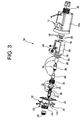
Figure 3 is an exploded view of the first embodiment of the valve system according to the invention; -
Figure 4 is a cross-sectional view along the line IV-IV ofFigure 2 ; -
Figure 5 is a view, on a larger scale, of the details indicated by the line V-V inFigure 4 ; and -
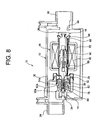
Figures 6 to 9 show schematic views of a sequence of operating configurations which the first embodiment of the valve system shown in the preceding figures is able to assume; -
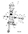
Figure 10 is an exploded view of a second embodiment of the valve system according to the present invention; -
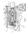
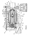
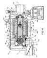
Figures 11 to 14 show schematic views of a sequence of operating configurations which the second embodiment of the valve system is able to assume; -
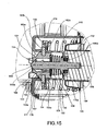
Figure 15 shows a detailed view of a portion of the second embodiment of the valve system; -
Figure 16 is a diagram showing an example of a characteristic curve for the flow rate of a fluid passing through the valve system expressed as a function of the intensity of an excitation current; and -
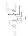
Figure 17 is a diagram illustrating the fluid flow of the valve system according to the present invention; -
Figure 18 shows a longitudinally sectioned view of a first constructional variation of the first valve device and applicable to the first or second embodiment of the valve system; -
Figure 19 is a cross-sectional view ofFigure 18 along the line XIX-XIX; -
Figure 20 shows a longitudinally sectioned view of a second constructional variant of the first inlet valve device and applicable to the first or second embodiments illustrated above; and -
Figure 21 is a cross-sectional view ofFigure 20 along the line XX-XX. - In the detailed description which follows terms or expressions such as "axial" or "axially", "radial" or "radially", "inwards" and "outwards" are understood as referring to the central axis A-A shown in
Figure 4 . - With reference in particular to
Figures 1 to 5 , 10 denotes a first example of embodiment of the valve system according to the present invention. Thisvalve system 10 is suitable for controlling the supply of a fluid from a supply source to a user apparatus. In a particularly advantageous manner thevalve system 10 is intended to be used for controlling the supply of a gas in a supply device, for example for a burner. - With reference in particular to
Figure 3 , thevalve system 10 comprises ahousing 12 which includes aninlet valve device 14, anelectromagnetic actuating device 16 and anoutlet valve device 18. - With reference in particular to
Figures 3 and4 , it can be seen that thehousing 12 is for example formed by a first substantially parallelepiped, hollow,container body 12a connected to a substantiallyrectangular cover 12b by means offixing screws 20. Aseal 22 is suitably arranged between thecontainer 12a and thecover 12b - The
cover 12b of thehousing 12 comprises aninlet joint 24, while anoutlet joint 26 is located at the opposite end of thecontainer 12a. Theinlet joint 24 and theoutlet joint 26 are intended, respectively, to receive a fluid flow from the external supply source (not shown) and to supply this fluid flow to a user apparatus (not shown). Afilter 28 is also installed inside the mouth of theinlet joint 24. - As can be seen more clearly in
Figures 4 and5 , theinlet joint 24 is in fluid communication by means of thefirst valve device 14 with amiddle section 30 which in turn communicates via thesecond valve device 18 with theoutlet joint 26. - With reference in particular to
Figures 3 and4 , thefirst valve device 14 comprises a firstmovable unit 32, a secondmovable unit 34 and afirst closing spring 36 and a shut-offspring 38. - With reference in particular to
Figures 4 and5 , the firstmovable unit 32 comprises preferably anouter cup member 40, aninner cup member 42 and anactuating stem 44. - The
outer cup member 40 has a hollow flared shape with at one axial end a first substantially planar bearingportion 46 extending radially. At the other axial end, theouter cup member 40 widens into an outer flangedportion 48 which is directed outwards. The actuatingstem 44 is mounted so as to be coaxial with thebearing portion 46. - The
inner cup member 42 also has a hollow flared shape, but comprises internally a push-piece 50 which has in the vicinity of its distal end a modulating shut-offsurface 50a with a substantially frustoconical shape. The push-piece 50 also has anaxial cavity 51 inside which the actuatingstem 44 is seated. Thedistal end 44a of the actuatingstem 44 bears against thebottom 51a of thecavity 51. Awasher 53 is stably fixed around the distal end of the push-piece 50. - In a similar manner to the
outer cup member 40, theinner cup member 42 also includes at an axial end a second bearingportion 52 which extends radially outwards from the push-piece 50 and has a substantially planar shape. At the other axial end, theinner cup member 42 widens into a second flangedportion 54 which has a first intercepting shut-offsurface 54a. - During assembly the
outer cup member 40 and theinner cup member 42 are in contact with each other via the respective bearingportions - The actuating
stem 44 has a diametrally widenedportion 44b which is arranged inside arecess 56 formed between the bearingportions outer cup member 40 and theinner cup member 42. - The second
movable unit 34 comprises asleeve 58 with an axial cavity aligned with theinner cup member 42. Thesleeve 58 has externally along an axially middle section thereof a first radiallyouter shoulder 60 inside which aperipheral seal 62 is inserted. Thesleeve 58 houses and guides slidably inside it the push-piece 50 and in turn is partially inserted with the possibility of relative sliding within theinner cup member 42 inside the annular interstice situated between said push-piece 50 and the second flangedportion 54. The shut-offspring 38 is arranged between the second bearingportion 52 and thefirst shoulder 60. - On the opposite side to that directed towards the
inner cup member 42, thesleeve 58 also has atapered nose piece 65 which has at its end asecond shoulder 63 arranged radially more inwards than thefirst shoulder 60. Furthermore thetapered nose piece 65 has an axial cavity containing a first modulatingvalve seat 64 associated with the first modulating shut-offsurface 50a, while an axially directed side of theseal 62 provides a firstintercepting valve seat 62a for the first intercepting shut-offsurface 54a. - The
tapered nose piece 65 also has a radially external side surface which defines a second modulating shut-off surface 65a, the operation of which will be clarified below in the remainder of the present description. Furthermore, four rod-shaped ends 68 (only two of which are visible) extend from thetapered nose piece 65, from diametrically opposite positions, and merge together in anannular guide ring 66. - The
cover 12b has internally afrustoconical pin 70 which during assembly passes through an axial opening defined in theannular guide ring 66. Preferably but not necessarily, anopposition spring 72, which helps to keep the push-piece 50 and thesleeve 58 in their respective relative positions is arranged between thewasher 53 and thefrustoconical pin 70. - The
cover 12b comprises furthermoretubular walls 74 which surround thefrustoconical pin 70 and are intended to guide thesleeve 58 in an axially sliding manner. The tubularinner walls 74 provide a secondintercepting valve seat 76 defined at their axial end which during assembly is directed towards theseal 62. Therefore on a side opposite to the firstintercepting valve seat 62a, theseal 62 has a second shut-off surface 62b which is suitable for making bearing contact against the secondintercepting valve seat 76. - Furthermore the
tubular walls 74 have a second modulatingvalve seat 77 formed by their radially inner surface which operationally faces the second modulating shut-offsurface 65a of thetapered nose piece 65 of the sleeve. - As will become clear from the remainder of the present description, the
first valve device 14 is able to provide modulated regulation of the fluid flow supplied from theinlet joint 24 and directed towards themiddle section 30. - With reference in particular to
Figures 3 and4 , theelectromagnetic actuating device 16 is contained in a fluid tight manner inside themiddle section 30 and comprises atubular part 78 with a widenedportion 80 fitted around the tubularinner walls 74 of thecover 12a of thehousing 12 by means of afirst seal 82, and anarrow portion 84. - The
actuating device 16 also comprises a first core and a second core offerromagnetic material narrow portion 84 and separated in a fluid-tight manner by a fixedstop portion 90. Thenarrow portion 84 is surrounded by aninduction coil 92 embedded in ahollow body 93 and is therefore sealingly closed with respect to themiddle section 30. Thehollow body 93 is fixed to thecontainer 12b via fastening means 95 (seeFigures 3 and4 ) which are known per se. - The actuating
stem 44 is stably fixed to thefirst core 86, while asecond closing spring 94 is arranged between thesecond core 88 and thestop portion 90. It should be noted that asecond seal 91 is located along a central section of the fixedstop portion 90, being arranged between the outer surface of thisstop portion 90 and the inner surface of thetubular part 78. - The first and
second seals tubular part 78 in the direction defined by the axis A-A. - The
outlet valve device 18 comprises an outlet shut-off member 96 with a metallic support 97 which are mounted on thesecond core 88 and anoutlet valve seat 98 formed in thehousing 12 and facing the outlet joint 26. Therefore, theoutlet valve device 18 allows (on/off type) interception of the fluid supplied from themiddle section 30 and directed into the outlet joint 26. - As can be seen in
Figures 1 to 5 , the first andsecond cores tubular part 78 in the direction of the same axis A-A (Figure 4 ) and in opposite senses. Theactuating device 16 is connected to an external control device (not shown) able to modulate suitably the intensity I of the excitation current flowing inside thecoil 92. - With reference to
Figures 6 to 9 , the operating principle of thevalve device 10 illustrated in the previous figures will now be described. These figures show schematically thevalve device 10 with the sole aim of illustrating its various operating configurations and therefore may have a number of small structural differences compared toFigures 1 to 5 , these not altering, however, the mode of operation thereof. - With reference to
Figure 6 , thevalve device 10 is shown in a completely closed configuration, where the first andsecond valve devices Figures 4 and5 ). - In this condition, the
first closing spring 36 pushes the firstmovable unit 32 so that the intercepting shut-offsurface 54a bears against the interceptingvalve seat 62a provided by theseal 62. - In turn, the first
movable unit 32 pushes theseal 62 so that its main inlet shut-offsurface 62b bears against the maininlet valve seat 76. - Moreover, the
second closing spring 94 keeps the outlet shut-off member 96 against the respectiveoutlet valve seat 98. - Consequently, the fluid entering into the inlet joint 24 is unable to access the
middle section 30 and the latter is not in fluid communication with the outlet joint 26. - With reference to
Figure 7 , thevalve system 10 is shown in a preliminary open configuration, where theinlet valve device 14 is in the completely closed condition, while theoutlet valve device 18 is in a completely open condition. - In this situation the
induction coil 92 is passed through by an electric current which has a intensity I less than a first supply threshold I1 (see alsoFigure 15 ). - On the one hand, the intensity I<I1 of the electric current is sufficient to excite the
second core 88, moving it from an extracted position (Figures 4 ,5 and6 ) into a retracted position (Figure 7 ), overcoming the resilient recall force of thesecond closing spring 94. In this way the outlet shut-off member 96 is recalled and raised from theoutlet valve seat 98, establishing fluid communication between themiddle section 30 and the outlet joint 26. - On the other hand this intensity I<I1 is insufficient to move the
first core 86, since thefirst closing spring 36 has dimensions suitable for opposing a resilient recall force greater than that exerted by thesecond closing spring 94 and greater than the electromagnetic force acting on thefirst core 86. Therefore, the fluid flow between the inlet joint 24 and themiddle section 30 is prevented. - With reference to
Figure 8 , thevalve system 10 is shown in a first modulated open configuration, where theinlet valve device 14 is in a first modulated open condition and theoutlet valve device 18 is in a completely open condition. - In this situation the
induction coil 92 is passed through by an electric current I which has an intensity I greater than the first supply threshold I1, but less than the second supply threshold I2 (seeFigure 15 ). - Compared to that which occurs in the preliminary open configuration, the intensity I1<I<I2 is sufficient to move the
first core 86 from a first extracted position (Figures 4 ,5 ,6 and7 ) into a partially retracted position (Figure 8 ) since the size of thefirst closing spring 36 is selected in such a way that the electromagnet force acting on thefirst core 86 overcomes the resilient recall force exerted by thefirst closing spring 36. - Consequently, the actuating
stem 44, which is displaceably locked with thefirst core 86, "drives" theouter cup 40 owing to the bearing action of the widenedportion 44b against the bearingportion 46. In this way the first intercepting shut-offsurface 54a is raised from the first interceptingvalve seat 62a of theseal 62, while the first modulating shut-offsurface 50a moves away from the firstmodulating valve seat 64. At the same time the shut-offspring 38 continues to exert a pressure on thefirst shoulder 60 and keeps the second intercepting shut-offsurface 62b pressed against the second interceptingvalve seat 76. - In this way the fluid supplied from the inlet joint 24 flows radially inwards inside the interstice formed in this modulated open configuration between the first and second
movable units surface 54a and the first interceptingvalve seat 62a. The fluid then flows through a second smaller annular aperture which has a cross-section which can be modulated depending on the travel of thefirst core 86 and is formed between the first modulating shut-offsurface 50a and the firstmodulating valve seat 64. - Consequently, the fluid flows radially outwards from the
sleeve 58 along themiddle section 30 and is free to pass through the outlet joint 26. - In short, owing to the action of the
inlet valve device 14, the fluid supplied from the inlet joint 24 undergoes various changes in direction along its path inside thehousing 12 relative to the direction defined by the axis A-A. - Modulation of the fluid flow passing through the
first valve device 14 is dependent upon the current which passes through theinduction coil 92. In fact the intensity I1<I<I2 of the current is related to the degree of displacement of the first modulating shut-offsurface 50a away from the firstmodulating valve seat 64. - Referring to
Figures 15 and16 it can be noted that the flow rate Φ of the fluid passing through thefirst valve device 14 is a function of the current I, following a first section of a characteristic curve C1 which increases with an increase in the intensity of the current I. Along the first section of the characteristic curve C1 it can be seen that, for current intensity values I1<I<I2, the fluid flow rate Φ increases with a rate of increase k1. In this example of embodiment the first section of the characteristic curve C1 is substantially rectilinear, although the progression is to be regarded as purely indicative and not definitive. It is desirable to obtain a value for the rate of increase k1 which is as small as possible and an amplitude of the range I1<I<I2 which is as wide as possible so as to be able to obtain a greater "sensitivity" during control of the fluid flow rate Φ. - When the current intensity I is increased to reach the second supply threshold I2, the first
movable unit 32 is arranged so that thewasher 53 bears against thesecond shoulder 63 formed in the taperednose piece 65 of thesleeve 58. - With reference to
Figure 9 , thevalve system 10 is shown in a second modulated open configuration, where thefirst valve device 14 is in a second modulated open condition and thesecond valve device 18 is in a completely open condition. - In this situation the
induction coil 92 is passed through by an electric current I which has an intensity I greater than the second supply threshold I2. Compared to that which occurs in the modulated open configuration, the current I>I2 allows movement of the firstmovable unit 32 beyond the partially retracted portion of thefirst core 86 shown inFigure 8 . Owing to the bearing contact between thewasher 53 and thesecond shoulder 63, the secondmovable unit 34 is displaceably locked with the firstmovable unit 32 and therefore the second intercepting shut-offsurface 62b of theseal 62 is raised from the second interceptingvalve seat 76. - In this way, the fluid supplied from the inlet joint 24, in addition to flowing within the interstice formed between the first and second
movable units surface 62b of theseal 62 and the second interceptingvalve seat 76. Then the fluid passes through a fourth aperture present between the second modulating shut-offsurface 65a of the taperednose piece 65 of thesleeve 58 and the secondmodulating valve seat 77. In a similar manner to that which occurs in the operating configuration shown inFigure 8 , this fourth aperture allows modulation of the fluid flow rate Φ as a function of the current intensity I. - Referring to
Figures 15 and16 it can be noted that, for current intensity values I>I2, the fluid flow rate Φ follows a second section of the characteristic curve C2 which increases with an increase in the current intensity I. It should be noted that, as in the case of the first section of the characteristic curve C1, the progression of the second section of the characteristic curve C2 is to be regarded as purely indicative and not definitive. - From an examination of the second section of the characteristic curve C2 it can be seen that the fluid flow rate Φ increases with a rate of increase k2 greater than the first rate of increase k1 associated with the first section of the characteristic curve C1. This situation is due to the fact that, in the second modulated open condition, the cross-section of the fourth aperture present between the second modulating shut-off
surface 65a and the secondmodulating valve seat 77 is proportionally greater than the second aperture existing between the first modulating shut-offsurface 50a and the firstmodulating valve seat 64. - Therefore, this
valve system 10 may be set to two different modulated open conditions. In the first modulated open condition, shown inFigure 8 , it can be understood how thevalve system 10 allows precise and sensitive regulation of the fluid flow rate between the inlet joint 24 and the outlet joint 26. Instead, in the second modulated open condition shown inFigure 9 , it can be understood how thevalve system 10 allows "less sensitive" regulation of the fluid flow than that which is achieved for the first modulated open condition. - When the
electromagnetic actuating device 16 is de-energised, thevalve system 10 assumes again the initial completely closed configuration shown inFigures 4 to 6 by means of the action of thesprings - With reference to
Figures 10 to 15 , a second embodiment of the valve system according to the present invention is shown. Parts which are similar or analogous to those in the previous embodiment are indicated by the same reference numbers and letters preceded by 1. - For the sake of brevity, details which are identical or similar to those in the previous embodiment will not be described below, but some of the main characteristic features which differ from the valve system illustrated in the previous figures will be highlighted.
- Firstly reference is made to the constructional details of the first valve device, shown more clearly in
Figure 15 . - Differently from the first embodiment described above, the
cover 112b is mounted on top of thecontainer body 112a. - By way of a further difference from the first embodiment, the first
movable unit 132 does not have theinner cup member 42, the function of which is performed directly by the (outer)cup member 140. In this connection, thecup member 140 has an end projection directed in the radial direction and comprising a first substantiallyradial flange section 154 and asecond flange section 148 axially removed from the remainder of thecup member 140. Thefirst flange section 154 has the first interceptingsurface 154a, while thesecond flange section 148 bears against thefirst closing spring 136. - Differently from the first embodiment, the modulating shut-off
surface 150a is provided on the distal end of thestem 144. - Again differently from the first embodiment, the
washer 53 is not present and its "driving" function is performed by aradial projection 153 present along an axially middle portion of thestem 144. The abovementioned radial projection engages inside a correspondinggroove 153a formed in the secondmovable unit 134. - Differently from the first embodiment, the second
movable unit 134 has asleeve 158 with no regions which have the same function as thefirst shoulder 60 and thesecond shoulder 63. In fact, the shut-offspring 138 presses directly against an annular recessedportion 160 of thesleeve 158 and, as already described above, in the absence of thewasher 53 there is no longer the need for a corresponding shoulder. - Differently from the first embodiment, the
sleeve 158 does not have theannular guide ring 66, but has instead a plurality ofend teeth 168 projecting axially and shorter than the rod-shaped ends 68. - Differently from the first embodiment, the
frustoconical pin 70 andopposition spring 72, which have an essentially centring and guiding function, are absent. A function similar to that of the abovementioned parts is performed by theradial projection 153 and theaxial groove 153a. - A further difference from the first embodiment consists in replacement of the
inner walls 74 by a fixingbracket 174 made of metallic material and suitable for guiding the secondmovable unit 134. In a manner similar to that achieved in the first embodiment by means of theinner walls 74, the mountingbracket 174 also provides the second interceptingvalve seat 176 and the secondmodulating valve seat 177. In this way, the absence of theinner walls 74 simplifies the method for manufacture of thecover 112a and therefore theinner housing 112 which is typically performed by means of die-casting or similar processing methods. - By way of a further difference, it can be seen that a
seal 186a is located between thestem 144, thefirst core 186 and the bearingportion 146 of thecup member 140. - In this second embodiment of the system according to the present invention certain differences as regards the
actuating device 116 may also be noted. In order to appreciate these differences, reference should be made toFigures 10 to 14 . - Differently from the first embodiment, the
electromagnetic actuating device 16 comprises a firsttubular part 178a and a secondtubular part 178b. The firsttubular part 178a at one axial end is pressed against the mountingbracket 174 via anannular seal 182, while aclosed end wall 189 is present at the other axial end. Theend wall 189 of the firsttubular part 178a has a substantially finger-like shape which matches atapered end 186a of the firstferromagnetic core 186, when the latter is in the retracted position (seeFigure 14 ). Furthermore it can be noted how the secondtubular part 178b instead has a hollow through-shape and slidably houses inside it the secondferromagnetic core 188. The latter has a substantially frustoconicalaxial cavity 188a which matches the finger-like end wall 189 of the firsttubular part 178a. Furthermore, first and second noise-suppression elements tapered end 186a and the end wall of theaxial cavity 188a. The enlarged heads of the noise-suppression elements like end wall 189 and have the function of dampening the impact of theferromagnetic cores - Owing to this particular structure of the
actuating device 116 there is no need to use the fixedstop part 90 with the associatedseal 93, as instead occurs in the first embodiment. In this way assembly of thesystem 110 is simplified. A further advantage which arises as a result of the absence of the fixedstop part 90 is the improved efficiency of the magnetic circuit since it is possible to increase the size of thecores tubular parts - Moreover, as can be better appreciated with reference to
Figure 10 , the second embodiment of thesystem 110 envisages transverse mounting of the components inside thehousing 112 relative to the longitudinal axis A-A. Instead, with reference toFigure 3 , thefirst embodiment 10 envisages assembly substantially in the axial direction and parallel to the longitudinal axis A-A. - In any case, in both embodiments it can be noted how the
electromagnetic actuating device 16 is advantageously intended to be passed over externally by the fluid flow passing through themiddle section 30 and to have a convective heat exchange relationship with this fluid flow. - With reference to
Figures 18 and 19 , 214 denotes a possible constructional variation of the firstinlet valve device 114 of the second embodiment of thesystem 110. Parts which are similar or analogous to those of the second embodiment are indicated by the same reference numbers and letters, but preceded by the number 2 instead of 1. It can be noted how theinlet valve device 214 is also applicable to the first embodiment of thesystem 10. - For the sake of brevity, details which are identical or similar to those in the second embodiment of the system will not be described below, but some of the main characteristic features which differ from said embodiment will be highlighted.
- As can be seen in
Figure 18 , differently from the second embodiment, thefirst core 286 is integral with thesingle cup member 240. Thecup member 240 has substantially the same characteristic features as thecup member 140 of the second embodiment of the system. - Compared to the second embodiment, a different mechanism is used to guide the
actuating stem 244. In fact, in place of theradial projection 153 and thegroove 153a, thesleeve 258 has a first inner ring of guiding ribs orflanges 253 projecting radially inside the cavity of saidsleeve 258 and extending axially. The radially inner ends of the guidingflanges 253 are adapted to the outer side surface of theactuating stem 244 so as to guide the movement thereof. Furthermore, thesleeve 258 has a plurality of engaginglugs 253a which project in the direction of themovable core 286. These engaginglugs 253a are operationally intended to engage against driving portions (not visible in the figures) projecting radially inside the cavity defined by thecup 240. In this way, the bearing contact between the abovementioned driving portions and the engaging lugs has the same function as the bearing contact between theradial projection 153 and thegroove 153a (second embodiment shown inFigure 14 ) and between thewasher 53 and the bearing surface 63 (first embodiment shown inFigure 5 ), namely allows the transition from the first modulated open condition into the second modulated open condition. - By way of a further difference from the second embodiment, the
actuating stem 244 is not embedded in theferromagnetic core 286, but has a radiallyenlarged contact base 244a with a substantially convex end wall which is supported by the flat bearing surface of thecore 286. The shut-offspring 238 is arranged between the bearingbase 244a and thesleeve 258. Consequently the presence of theseal 186a is no longer required. - With reference to
Figures 20 and 21 , 314 denotes a possible constructional variant of the firstinlet valve device 214 of the variation of embodiment shown inFigures 18 and 19 . Parts which are similar or analogous to those of said variation of embodiment are indicated by the same reference numbers and letters, but have the number 3 instead of 2 in front. It can be noted how theinlet valve device 314 is compatible both with the first embodiment of thesystem 10 and with the second embodiment of thesystem 110. - For the sake of brevity, details which are identical or similar to those in the abovementioned first variation of embodiment shown in
Figures 18 and 19 will not be described below, but some of the main characteristic features which differ from said embodiment will be highlighted. - Differently from that shown in
Figures 18 and 19 , the end part of theactuating stem 344 comprises a radiallyenlarged portion 344a followed by an axial mushroom-shaped tail-piece 344b which has a narrower cross-section than the remainder of theactuating stem 344. Furthermore asupport part 387 is arranged between the core 386 and theactuating stem 344 and has a convexbearing end wall 387a which bears against the flat bearing surface of thecore 386 inside thecup 340. Thebearing part 387 has acentral recess 387b housing with interference the axial tail-piece 344b. The shut-offspring 338 is arranged between thesupport part 387 andsleeve 358, being housed inside a radially external region of thissupport part 387. Furthermore afurther positioning spring 385 is arranged between the radiallyenlarged portion 344a and anannular channel 387c formed around therecess 387b. - One of the advantages of the first and second variations of embodiment of the
valve device stem movable core movable core movable unit base 244a or the end wall of 387a and the flat surface of therespective core stem inlet valve device valve system 10. - In further variants not shown, which are applicable to both the first embodiment and the second embodiment, it may be envisaged that the
actuating device middle section housing - In other variants not shown, which are applicable to both the first embodiment and the second embodiment, the
valve system inlet valve device middle section middle section - Naturally, without modifying the principle of the invention, the embodiments and the constructional details may be greatly varied with respect to that described and illustrated purely by way of a non-limiting example, without thereby departing from the scope of the invention as defined in the accompanying claims.
Claims (25)
- Valve system (10; 110), in particular for controlling the supply of a fluid from a supply source to a user apparatus, said system comprising:a housing (12; 112) includingan inlet joint (24; 124) and an outlet joint (26; 126) intended to receive an incoming fluid flow and to discharge said fluid flow, respectively; anda middle section (30; 130) in fluid communication with the inlet joint (24; 124) and the outlet joint (26; 126), respectively;- inlet and outlet valve means (14; 114; 214; 314; 18; 118) arranged between the inlet joint (24; 124) and the middle section (30; 130) and between the middle section (30; 130) and the outlet joint (26; 126); and- electromagnetic actuating means (16; 116) designed to be passed through by an electric excitation current having an intensity (I) which can be modulated so that the actuating means (16; 116) arrange the inlet valve means (14; 114; 214; 314) in a modulated open condition where said fluid flow rate (Φ) increases with an increase in the intensity (I) of said current;
said electromagnetic actuating means (16; 116) being designed to be activated by a current with a modulated intensity (I);
the valve system (10; 110) being characterized in that
the inlet valve means (14; 114) comprise first and second inlet valves (54, 62; 62, 76) provided with first and second resilient closing means (36; 38), respectively tending to retain said inlet valves (54, 62; 62, 76) in a closed condition, and in that
the electromagnetic actuating means (16; 116) comprise one solenoid (92; 192) arranged for controlling both said inlet valves (54, 62; 62, 76) by controlling a first movable ferromagnetic core (86; 186; 286; 386) which is designed to assume
a rest position in which both inlet valves (54, 62; 62; 76) are closed, when said solenoid (92; 192) is deenergized, and
first and second working positions in which the first inlet valve (54, 62) and both inlet valves (54, 62; 62, 76), respectively, assume a modulated open condition, when the current (I) in said solenoid (92; 192) is modulated within first and second ranges of values, respectively. - Valve system according to Claim 1, in which in said first and second ranges of values the solenoid current (I) is increased in accordance with a first and second rate of increase (k1; k2), respectively, said first rate of increase (k1) being less than said second rate of increase (k2).
- Valve system according to Claim 1 or 2, in which the first movable unit (32; 132; 232; 332) and the second movable unit (34; 134; 234; 334) are mounted so as to be slidable relative to each other.
- System according to Claim 3, in which the first movable unit (32; 132; 232; 332) and the second movable unit (34; 134; 234; 334) are mounted so as to be coaxial with each other.
- Valve system according to any one of Claims 1 to 4, in which the first movable unit (32; 132; 232; 332) defines a first intercepting shut-off surface (54a; 154a; 254a; 354a) and the second movable unit (34; 134; 234; 334) defines a first intercepting valve seat (62a; 162a; 262a, 362a), said first resilient closing means (36; 136; 236; 336) tending to push the first intercepting shut-off surface (54a; 154a; 254a; 354a) against the first intercepting valve seat (62a; 162a; 262a; 362a).
- Valve system according to Claim 5, in which said actuating means (16) raise the intercepting shut-off surface (54a; 154a; 254a; 354a) from the first intercepting valve seat (62a; 162a; 262a; 362a) when the current intensity (I) is greater than a first minimum threshold value (I1) suitable for opposing the action of the first closing spring (36; 136; 236; 336).
- Valve system according to Claim 5 or 6, in which the first movable unit (32; 132; 232; 332) also defines a first modulating shut-off surface (50a; 150a; 250a; 350a) and the second movable unit (34; 134; 234; 334) defines a first modulating valve seat (64; 164; 264, 364), said first resilient closing means (36; 136; 236; 336) tending to reduce the distance between the fust modulating shut-off surface (50a; 150a; 250a; 350a) and the first modulating valve seat (64; 164; 264; 364).
- Valve system according to Claim 7, in which said actuating means (16) separate the first modulating shut-off surface (50a; 150a; 250a; 350a) from the first modulating valve seat (64; 164; 264; 364) and modulate the fluid flow rate (Φ) in accordance with a first section of a characteristic curve (C1) when said current intensity (I) lies between a first minimum threshold value (I1) and a second maximum threshold value (I2).
- Valve system according to Claim 7 or 8, in which the second movable unit (34; 134; 234; 334) also defines a second intercepting shut-off surface (62b; 162b; 262b; 362b) and the housing (12; 112) defines a second intercepting valve seat (76; 176), said inlet valve means (14; 114; 214; 314) also comprising second resillient closing means (38; 138; 238; 338) tending to retain the second intercepting shut-off surface (62b; 162b; 262b; 362b) against the second intercepting valve seat (76; 176).
- Valve system according to Claim 9, in which the first intercepting valve seat (62a; 162a; 262a; 362a) is integral with the second intercepting shut-off surface (62b; 162b; 262b; 362b).
- Valve system according to Claim 9 or 10, in which said second resilient closing means (38; 138; 238; 338) are arranged between the first movable unit (32; 132; 232; 332) and the second movable unit (34; 134; 234; 334).
- Valve system according to any one of Claims 9 to 11, in which the first movable unit (32; 132; 232; 332) causes raising of the second intercepting shut-off surface (62b; 162b; 262b; 362b) from the second intercepting valve seat (76; 176) when the actuating means (16; 116) are passed through by a current with an intensity (I) greater than a second maximum threshold value (I2).
- Valve system according to either one of Claims 11 or 12, in which the second movable unit (32; 132; 232; 332) also defines a second modulating shut-off surface (65a; 165a; 265a; 365a) and the housing (12; 112) defines a second modulating valve seat (77; 177), said first resilient closing means (36; 136; 236; 336) tending to reduce the distance between the second modulating shut-off surface (65a; 165a; 265a; 365a) and the second modulating valve seat (77; 177).
- Valve system according to Claims 8 and 13, in which said actuating means (16) separate the second modulating shut-off surface (65a; 165a; 265a; 365a) from the second modulating valve seat (77; 177) and modulate the fluid flow rate (Φ) in accordance with a second section of the characteristic curve (C2) when the current intensity (I) is greater than said maximum threshold value (I2).
- Valve system according to any one of Claims 7 to 14, in which the first intercepting shut-off surface (54a; 154a; 254a; 354a) and the first intercepting valve seat (62a; 162a; 262a; 362a) are located upstream of the first modulating shut-off surface (50a; 150a; 250a; 350a) and the associated first modulating valve seat (64; 164; 264; 364).
- Valve system according to Claim 15, in which the first intercepting shut-off surface (54a; 154a; 254a; 354a) and the first intercepting valve seat (62a; 162a; 262a; 362a) are located in a radially external position with respect to the first modulating shut-off surface (50a; 150a; 250a; 350a) and the associated first modulating valve seat (64; 164; 264; 364).
- Valve system according to any one of Claims 13 to 16, in which the second intercepting shut-off surface (62b; 162b; 262b; 362b) and the second intercepting valve seat (76; 176) are located upstream of the second modulating shut-off surface (65a; 165a; 265a; 365a) and the associated second modulating valve seat (77; 177).
- Valve system according to Claim 17, in which the second intercepting shut-off surface (62b; 162b; 262b; 362b) and the second shut-off valve seat (76; 176) are located in a radially external position with respect to the second modulating shut-off surface (65a; 165a; 265a; 365a) and the associated second modulating valve seat (77; 177).
- Valve system according to any one of the preceding claims, in which the electromagnetic actuating means (16; 116) are located internally in a fluid-tight manner in the middle section (30; 130) of the housing (12; 112).
- Valve system according to any one of Claims 1 to 18, in which the electromagnetic actuating means are located outside of the middle section of the housing (12).
- Valve system according to any of the preceding Claims, in which the first movable unit (232; 332) also comprises a part mounted so as to be pivotable with respect to the first ferromagnetic core (286; 386) and the remainder of said first movable unit (232; 332) and guided by said second movable unit (234; 334).
- Valve system according to Claim 21, in which the actuating means (16; 116) also comprise a second ferromagnetic core (88; 188) surrounded by the solenoid (92; 192) and designed to operate the outlet valve means (18; 118).
- Valve system according to Claim 22, in which the first core (86; 186; 286; 386) and the second core (88; 188) are displaceable in opposite senses along the same direction (A-A).
- Valve system according to Claim 23, in which the first core (86) and the second core (88) are axially displaceable in a fluid-tight manner by a fixed stop member (90).
- System according to Claim, 19, in which said electromagnetic actuating means (16, 116) are intended to be passed over externally by the fluid flow passing through the middle section (30; 130) and to have a convective heat exchange relationship with said fluid flow.
Priority Applications (1)
| Application Number | Priority Date | Filing Date | Title |
|---|---|---|---|
| PL09711590T PL2247880T3 (en) | 2008-02-22 | 2009-02-20 | Valve system, in particular for controlling the supply of a fluid from a supply source to a user apparatus |
Applications Claiming Priority (2)
| Application Number | Priority Date | Filing Date | Title |
|---|---|---|---|
| IT000134A ITTO20080134A1 (en) | 2008-02-22 | 2008-02-22 | VALVE SYSTEM, PARTICULARLY FOR THE CONTROL OF THE DISTRIBUTION OF A FLUID FROM A POWER SOURCE TO A USER APPLIANCE |
| PCT/IB2009/050700 WO2009104158A2 (en) | 2008-02-22 | 2009-02-20 | Valve system, in particular for controlling the supply of a fluid from a supply source to a user apparatus |
Publications (3)
| Publication Number | Publication Date |
|---|---|
| EP2247880A2 EP2247880A2 (en) | 2010-11-10 |
| EP2247880B1 true EP2247880B1 (en) | 2011-10-26 |
| EP2247880B8 EP2247880B8 (en) | 2012-04-25 |
Family
ID=40292008
Family Applications (1)
| Application Number | Title | Priority Date | Filing Date |
|---|---|---|---|
| EP09711590A Not-in-force EP2247880B8 (en) | 2008-02-22 | 2009-02-20 | Valve system, in particular for controlling the supply of a fluid from a supply source to a user apparatus |
Country Status (7)
| Country | Link |
|---|---|
| EP (1) | EP2247880B8 (en) |
| CN (1) | CN101978203B (en) |
| AT (1) | ATE530827T1 (en) |
| ES (1) | ES2372669T3 (en) |
| IT (1) | ITTO20080134A1 (en) |
| PL (1) | PL2247880T3 (en) |
| WO (1) | WO2009104158A2 (en) |
Families Citing this family (3)
| Publication number | Priority date | Publication date | Assignee | Title |
|---|---|---|---|---|
| ITTO20111148A1 (en) * | 2011-12-14 | 2013-06-15 | Elbi Int Spa | SOLENOID PILOT VALVE FOR A HYDRAULIC VALVE, PARTICULARLY FOR APPLIANCES |
| WO2016133974A1 (en) | 2015-02-17 | 2016-08-25 | Enfield Technologies, Inc. | Solenoid apparatus |
| DE102017203703A1 (en) * | 2017-03-07 | 2018-09-13 | Robert Bosch Gmbh | Valve arrangement for a solenoid valve and corresponding solenoid valve |
Family Cites Families (4)
| Publication number | Priority date | Publication date | Assignee | Title |
|---|---|---|---|---|
| US5450876A (en) * | 1994-05-11 | 1995-09-19 | Marotta Scientific Controls, Inc. | Magnetically linked valve construction |
| EP1106922A1 (en) * | 1999-12-02 | 2001-06-13 | Vanni Gallocchio | Safety and/or flow control valve, particularly for gas |
| FR2821915B1 (en) * | 2001-03-06 | 2004-03-05 | App S Electro Mecaniques Du Fa | GAS FLOW CONTROL AND SECURITY DEVICE |
| DE102006041872B3 (en) * | 2006-08-31 | 2007-12-20 | Saia-Burgess Dresden Gmbh | Gas regulation and safety valve for burner of gas heating mechanism, has housing with closing units, where one of closing units is driven from spindle nut system, and other unit has sealing body, which is connected with anchor |
-
2008
- 2008-02-22 IT IT000134A patent/ITTO20080134A1/en unknown
-
2009
- 2009-02-20 CN CN2009801059264A patent/CN101978203B/en not_active Expired - Fee Related
- 2009-02-20 WO PCT/IB2009/050700 patent/WO2009104158A2/en not_active Ceased
- 2009-02-20 PL PL09711590T patent/PL2247880T3/en unknown
- 2009-02-20 ES ES09711590T patent/ES2372669T3/en active Active
- 2009-02-20 EP EP09711590A patent/EP2247880B8/en not_active Not-in-force
- 2009-02-20 AT AT09711590T patent/ATE530827T1/en not_active IP Right Cessation
Also Published As
| Publication number | Publication date |
|---|---|
| WO2009104158A3 (en) | 2010-08-05 |
| ATE530827T1 (en) | 2011-11-15 |
| CN101978203A (en) | 2011-02-16 |
| PL2247880T3 (en) | 2012-03-30 |
| ITTO20080134A1 (en) | 2009-08-23 |
| CN101978203B (en) | 2013-10-16 |
| EP2247880B8 (en) | 2012-04-25 |
| WO2009104158A9 (en) | 2010-09-23 |
| EP2247880A2 (en) | 2010-11-10 |
| ES2372669T3 (en) | 2012-01-25 |
| WO2009104158A2 (en) | 2009-08-27 |
Similar Documents
| Publication | Publication Date | Title |
|---|---|---|
| US11682776B2 (en) | Metering valve and jet pump unit for controlling a gaseous medium | |
| JP4020477B2 (en) | Pressure fluid pressure adjustment method and proportional variable force solenoid pressure adjustment valve | |
| EP2247880B8 (en) | Valve system, in particular for controlling the supply of a fluid from a supply source to a user apparatus | |
| EP2215406B1 (en) | Multifunctional safety valve device with incorporated proportional pressure regulator | |
| KR102478295B1 (en) | Proportional valves for controlling gaseous media | |
| JP6103150B2 (en) | Extraction valve and how to use the extraction valve | |
| CA2459088A1 (en) | Leak-resistant solenoid valve | |
| CN100414156C (en) | valves for controlling fluids | |
| KR20010034287A (en) | Hydraulic magnetically actuated seat valve, especially for motor vehicle braking systems | |
| EP3006796B1 (en) | Dual plunger solenoid valve | |
| RU2000129145A (en) | GAS VALVE AND METHOD OF GAS PULSE SUPPLY | |
| EP3919795B1 (en) | Electromagnetic gas valve | |
| CN105579696B (en) | Fluid injection valve | |
| EP1907737B1 (en) | Liquid flow valve with a bistable electromagnetic control assembly | |
| CN107429850A (en) | Valve For Controlling The Flow Of A Fluid | |
| EP0669499B1 (en) | Device for regulating and controlling the flow of gas to burners of domestic boilers | |
| CN112747162A (en) | Gas proportional valve | |
| GB1574996A (en) | Valve | |
| KR20210016376A (en) | Valves for fluid, preferably gas | |
| DK173042B1 (en) | Solenoid valve | |
| KR200459709Y1 (en) | Direct-acting type Electric Valve | |
| CN114761715B (en) | Valve for fluids, preferably gases | |
| RU2169874C2 (en) | Shut-off valve | |
| WO2019115828A1 (en) | Pilot controlled electromagnetic valve with auxiliary piston | |
| WO2007098790A1 (en) | A valve unit for controlling a combustible gas supply |
Legal Events
| Date | Code | Title | Description |
|---|---|---|---|
| PUAI | Public reference made under article 153(3) epc to a published international application that has entered the european phase |
Free format text: ORIGINAL CODE: 0009012 |
|
| 17P | Request for examination filed |
Effective date: 20100824 |
|
| AK | Designated contracting states |
Kind code of ref document: A2 Designated state(s): AT BE BG CH CY CZ DE DK EE ES FI FR GB GR HR HU IE IS IT LI LT LU LV MC MK MT NL NO PL PT RO SE SI SK TR |
|
| AX | Request for extension of the european patent |
Extension state: AL BA RS |
|
| GRAP | Despatch of communication of intention to grant a patent |
Free format text: ORIGINAL CODE: EPIDOSNIGR1 |
|
| DAX | Request for extension of the european patent (deleted) | ||
| GRAS | Grant fee paid |
Free format text: ORIGINAL CODE: EPIDOSNIGR3 |
|
| GRAA | (expected) grant |
Free format text: ORIGINAL CODE: 0009210 |
|
| AK | Designated contracting states |
Kind code of ref document: B1 Designated state(s): AT BE BG CH CY CZ DE DK EE ES FI FR GB GR HR HU IE IS IT LI LT LU LV MC MK MT NL NO PL PT RO SE SI SK TR |
|
| REG | Reference to a national code |
Ref country code: GB Ref legal event code: FG4D |
|
| REG | Reference to a national code |
Ref country code: CH Ref legal event code: EP |
|
| REG | Reference to a national code |
Ref country code: IE Ref legal event code: FG4D |
|
| REG | Reference to a national code |
Ref country code: DE Ref legal event code: R096 Ref document number: 602009003330 Country of ref document: DE Effective date: 20120119 |
|
| REG | Reference to a national code |
Ref country code: ES Ref legal event code: FG2A Ref document number: 2372669 Country of ref document: ES Kind code of ref document: T3 Effective date: 20120125 |
|
| REG | Reference to a national code |
Ref country code: NL Ref legal event code: T3 |
|
| LTIE | Lt: invalidation of european patent or patent extension |
Effective date: 20111026 |
|
| REG | Reference to a national code |
Ref country code: PL Ref legal event code: T3 |
|
| REG | Reference to a national code |
Ref country code: AT Ref legal event code: MK05 Ref document number: 530827 Country of ref document: AT Kind code of ref document: T Effective date: 20111026 |
|
| PG25 | Lapsed in a contracting state [announced via postgrant information from national office to epo] |
Ref country code: BE Free format text: LAPSE BECAUSE OF FAILURE TO SUBMIT A TRANSLATION OF THE DESCRIPTION OR TO PAY THE FEE WITHIN THE PRESCRIBED TIME-LIMIT Effective date: 20111026 Ref country code: LT Free format text: LAPSE BECAUSE OF FAILURE TO SUBMIT A TRANSLATION OF THE DESCRIPTION OR TO PAY THE FEE WITHIN THE PRESCRIBED TIME-LIMIT Effective date: 20111026 Ref country code: NO Free format text: LAPSE BECAUSE OF FAILURE TO SUBMIT A TRANSLATION OF THE DESCRIPTION OR TO PAY THE FEE WITHIN THE PRESCRIBED TIME-LIMIT Effective date: 20120126 Ref country code: IS Free format text: LAPSE BECAUSE OF FAILURE TO SUBMIT A TRANSLATION OF THE DESCRIPTION OR TO PAY THE FEE WITHIN THE PRESCRIBED TIME-LIMIT Effective date: 20120226 |
|
| PG25 | Lapsed in a contracting state [announced via postgrant information from national office to epo] |
Ref country code: SE Free format text: LAPSE BECAUSE OF FAILURE TO SUBMIT A TRANSLATION OF THE DESCRIPTION OR TO PAY THE FEE WITHIN THE PRESCRIBED TIME-LIMIT Effective date: 20111026 Ref country code: HR Free format text: LAPSE BECAUSE OF FAILURE TO SUBMIT A TRANSLATION OF THE DESCRIPTION OR TO PAY THE FEE WITHIN THE PRESCRIBED TIME-LIMIT Effective date: 20111026 Ref country code: SI Free format text: LAPSE BECAUSE OF FAILURE TO SUBMIT A TRANSLATION OF THE DESCRIPTION OR TO PAY THE FEE WITHIN THE PRESCRIBED TIME-LIMIT Effective date: 20111026 Ref country code: GR Free format text: LAPSE BECAUSE OF FAILURE TO SUBMIT A TRANSLATION OF THE DESCRIPTION OR TO PAY THE FEE WITHIN THE PRESCRIBED TIME-LIMIT Effective date: 20120127 Ref country code: LV Free format text: LAPSE BECAUSE OF FAILURE TO SUBMIT A TRANSLATION OF THE DESCRIPTION OR TO PAY THE FEE WITHIN THE PRESCRIBED TIME-LIMIT Effective date: 20111026 Ref country code: PT Free format text: LAPSE BECAUSE OF FAILURE TO SUBMIT A TRANSLATION OF THE DESCRIPTION OR TO PAY THE FEE WITHIN THE PRESCRIBED TIME-LIMIT Effective date: 20120227 |
|
| PG25 | Lapsed in a contracting state [announced via postgrant information from national office to epo] |
Ref country code: CY Free format text: LAPSE BECAUSE OF FAILURE TO SUBMIT A TRANSLATION OF THE DESCRIPTION OR TO PAY THE FEE WITHIN THE PRESCRIBED TIME-LIMIT Effective date: 20111026 |
|
| PG25 | Lapsed in a contracting state [announced via postgrant information from national office to epo] |
Ref country code: SK Free format text: LAPSE BECAUSE OF FAILURE TO SUBMIT A TRANSLATION OF THE DESCRIPTION OR TO PAY THE FEE WITHIN THE PRESCRIBED TIME-LIMIT Effective date: 20111026 Ref country code: CZ Free format text: LAPSE BECAUSE OF FAILURE TO SUBMIT A TRANSLATION OF THE DESCRIPTION OR TO PAY THE FEE WITHIN THE PRESCRIBED TIME-LIMIT Effective date: 20111026 Ref country code: EE Free format text: LAPSE BECAUSE OF FAILURE TO SUBMIT A TRANSLATION OF THE DESCRIPTION OR TO PAY THE FEE WITHIN THE PRESCRIBED TIME-LIMIT Effective date: 20111026 Ref country code: DK Free format text: LAPSE BECAUSE OF FAILURE TO SUBMIT A TRANSLATION OF THE DESCRIPTION OR TO PAY THE FEE WITHIN THE PRESCRIBED TIME-LIMIT Effective date: 20111026 Ref country code: BG Free format text: LAPSE BECAUSE OF FAILURE TO SUBMIT A TRANSLATION OF THE DESCRIPTION OR TO PAY THE FEE WITHIN THE PRESCRIBED TIME-LIMIT Effective date: 20120126 |
|
| PG25 | Lapsed in a contracting state [announced via postgrant information from national office to epo] |
Ref country code: RO Free format text: LAPSE BECAUSE OF FAILURE TO SUBMIT A TRANSLATION OF THE DESCRIPTION OR TO PAY THE FEE WITHIN THE PRESCRIBED TIME-LIMIT Effective date: 20111026 Ref country code: IT Free format text: LAPSE BECAUSE OF FAILURE TO SUBMIT A TRANSLATION OF THE DESCRIPTION OR TO PAY THE FEE WITHIN THE PRESCRIBED TIME-LIMIT Effective date: 20111026 |
|
| PLBE | No opposition filed within time limit |
Free format text: ORIGINAL CODE: 0009261 |
|
| STAA | Information on the status of an ep patent application or granted ep patent |
Free format text: STATUS: NO OPPOSITION FILED WITHIN TIME LIMIT |
|
| PG25 | Lapsed in a contracting state [announced via postgrant information from national office to epo] |
Ref country code: MC Free format text: LAPSE BECAUSE OF NON-PAYMENT OF DUE FEES Effective date: 20120229 |
|
| 26N | No opposition filed |
Effective date: 20120727 |
|
| REG | Reference to a national code |
Ref country code: IE Ref legal event code: MM4A |
|
| REG | Reference to a national code |
Ref country code: DE Ref legal event code: R097 Ref document number: 602009003330 Country of ref document: DE Effective date: 20120727 |
|
| PG25 | Lapsed in a contracting state [announced via postgrant information from national office to epo] |
Ref country code: AT Free format text: LAPSE BECAUSE OF FAILURE TO SUBMIT A TRANSLATION OF THE DESCRIPTION OR TO PAY THE FEE WITHIN THE PRESCRIBED TIME-LIMIT Effective date: 20111026 Ref country code: IE Free format text: LAPSE BECAUSE OF NON-PAYMENT OF DUE FEES Effective date: 20120220 |
|
| PG25 | Lapsed in a contracting state [announced via postgrant information from national office to epo] |
Ref country code: MK Free format text: LAPSE BECAUSE OF FAILURE TO SUBMIT A TRANSLATION OF THE DESCRIPTION OR TO PAY THE FEE WITHIN THE PRESCRIBED TIME-LIMIT Effective date: 20111026 |
|
| PG25 | Lapsed in a contracting state [announced via postgrant information from national office to epo] |
Ref country code: FI Free format text: LAPSE BECAUSE OF FAILURE TO SUBMIT A TRANSLATION OF THE DESCRIPTION OR TO PAY THE FEE WITHIN THE PRESCRIBED TIME-LIMIT Effective date: 20111026 |
|
| PG25 | Lapsed in a contracting state [announced via postgrant information from national office to epo] |
Ref country code: MT Free format text: LAPSE BECAUSE OF FAILURE TO SUBMIT A TRANSLATION OF THE DESCRIPTION OR TO PAY THE FEE WITHIN THE PRESCRIBED TIME-LIMIT Effective date: 20111026 |
|
| REG | Reference to a national code |
Ref country code: CH Ref legal event code: PL |
|
| PG25 | Lapsed in a contracting state [announced via postgrant information from national office to epo] |
Ref country code: LI Free format text: LAPSE BECAUSE OF NON-PAYMENT OF DUE FEES Effective date: 20130228 Ref country code: CH Free format text: LAPSE BECAUSE OF NON-PAYMENT OF DUE FEES Effective date: 20130228 |
|
| PG25 | Lapsed in a contracting state [announced via postgrant information from national office to epo] |
Ref country code: LU Free format text: LAPSE BECAUSE OF NON-PAYMENT OF DUE FEES Effective date: 20120220 |
|
| PG25 | Lapsed in a contracting state [announced via postgrant information from national office to epo] |
Ref country code: HU Free format text: LAPSE BECAUSE OF FAILURE TO SUBMIT A TRANSLATION OF THE DESCRIPTION OR TO PAY THE FEE WITHIN THE PRESCRIBED TIME-LIMIT Effective date: 20090220 |
|
| REG | Reference to a national code |
Ref country code: FR Ref legal event code: PLFP Year of fee payment: 8 |
|
| REG | Reference to a national code |
Ref country code: FR Ref legal event code: PLFP Year of fee payment: 9 |
|
| REG | Reference to a national code |
Ref country code: FR Ref legal event code: PLFP Year of fee payment: 10 |
|
| PGFP | Annual fee paid to national office [announced via postgrant information from national office to epo] |
Ref country code: ES Payment date: 20200302 Year of fee payment: 12 Ref country code: GB Payment date: 20200219 Year of fee payment: 12 |
|
| PGFP | Annual fee paid to national office [announced via postgrant information from national office to epo] |
Ref country code: FR Payment date: 20200228 Year of fee payment: 12 Ref country code: TR Payment date: 20200209 Year of fee payment: 12 |
|
| PGFP | Annual fee paid to national office [announced via postgrant information from national office to epo] |
Ref country code: DE Payment date: 20200430 Year of fee payment: 12 Ref country code: NL Payment date: 20200430 Year of fee payment: 12 |
|
| PGFP | Annual fee paid to national office [announced via postgrant information from national office to epo] |
Ref country code: PL Payment date: 20210115 Year of fee payment: 13 |
|
| REG | Reference to a national code |
Ref country code: DE Ref legal event code: R119 Ref document number: 602009003330 Country of ref document: DE |
|
| GBPC | Gb: european patent ceased through non-payment of renewal fee |
Effective date: 20210220 |
|
| REG | Reference to a national code |
Ref country code: NL Ref legal event code: MM Effective date: 20210301 |
|
| PG25 | Lapsed in a contracting state [announced via postgrant information from national office to epo] |
Ref country code: NL Free format text: LAPSE BECAUSE OF NON-PAYMENT OF DUE FEES Effective date: 20210301 |
|
| PG25 | Lapsed in a contracting state [announced via postgrant information from national office to epo] |
Ref country code: DE Free format text: LAPSE BECAUSE OF NON-PAYMENT OF DUE FEES Effective date: 20210901 Ref country code: FR Free format text: LAPSE BECAUSE OF NON-PAYMENT OF DUE FEES Effective date: 20210228 Ref country code: GB Free format text: LAPSE BECAUSE OF NON-PAYMENT OF DUE FEES Effective date: 20210220 |
|
| REG | Reference to a national code |
Ref country code: ES Ref legal event code: FD2A Effective date: 20220513 |
|
| PG25 | Lapsed in a contracting state [announced via postgrant information from national office to epo] |
Ref country code: TR Free format text: LAPSE BECAUSE OF NON-PAYMENT OF DUE FEES Effective date: 20210220 |
|
| PG25 | Lapsed in a contracting state [announced via postgrant information from national office to epo] |
Ref country code: ES Free format text: LAPSE BECAUSE OF NON-PAYMENT OF DUE FEES Effective date: 20210221 |
|
| PG25 | Lapsed in a contracting state [announced via postgrant information from national office to epo] |
Ref country code: PL Free format text: LAPSE BECAUSE OF NON-PAYMENT OF DUE FEES Effective date: 20220220 |