EP1907737B1 - Liquid flow valve with a bistable electromagnetic control assembly - Google Patents
Liquid flow valve with a bistable electromagnetic control assembly Download PDFInfo
- Publication number
- EP1907737B1 EP1907737B1 EP06777871A EP06777871A EP1907737B1 EP 1907737 B1 EP1907737 B1 EP 1907737B1 EP 06777871 A EP06777871 A EP 06777871A EP 06777871 A EP06777871 A EP 06777871A EP 1907737 B1 EP1907737 B1 EP 1907737B1
- Authority
- EP
- European Patent Office
- Prior art keywords
- armature
- valve
- core
- magnetic pole
- stable position
- Prior art date
- Legal status (The legal status is an assumption and is not a legal conclusion. Google has not performed a legal analysis and makes no representation as to the accuracy of the status listed.)
- Active
Links
- 239000007788 liquid Substances 0.000 title claims abstract description 20
- 230000005291 magnetic effect Effects 0.000 claims abstract description 72
- 230000004907 flux Effects 0.000 claims abstract description 29
- 230000003993 interaction Effects 0.000 abstract 1
- 239000012528 membrane Substances 0.000 description 9
- 230000006835 compression Effects 0.000 description 2
- 238000007906 compression Methods 0.000 description 2
- 239000003302 ferromagnetic material Substances 0.000 description 1
- 239000011810 insulating material Substances 0.000 description 1
- 239000011347 resin Substances 0.000 description 1
- 229920005989 resin Polymers 0.000 description 1
- 230000000717 retained effect Effects 0.000 description 1
- 230000035939 shock Effects 0.000 description 1
Images


Classifications
-
- F—MECHANICAL ENGINEERING; LIGHTING; HEATING; WEAPONS; BLASTING
- F16—ENGINEERING ELEMENTS AND UNITS; GENERAL MEASURES FOR PRODUCING AND MAINTAINING EFFECTIVE FUNCTIONING OF MACHINES OR INSTALLATIONS; THERMAL INSULATION IN GENERAL
- F16K—VALVES; TAPS; COCKS; ACTUATING-FLOATS; DEVICES FOR VENTING OR AERATING
- F16K31/00—Actuating devices; Operating means; Releasing devices
- F16K31/12—Actuating devices; Operating means; Releasing devices actuated by fluid
- F16K31/36—Actuating devices; Operating means; Releasing devices actuated by fluid in which fluid from the circuit is constantly supplied to the fluid motor
- F16K31/40—Actuating devices; Operating means; Releasing devices actuated by fluid in which fluid from the circuit is constantly supplied to the fluid motor with electrically-actuated member in the discharge of the motor
- F16K31/402—Actuating devices; Operating means; Releasing devices actuated by fluid in which fluid from the circuit is constantly supplied to the fluid motor with electrically-actuated member in the discharge of the motor acting on a diaphragm
- F16K31/404—Actuating devices; Operating means; Releasing devices actuated by fluid in which fluid from the circuit is constantly supplied to the fluid motor with electrically-actuated member in the discharge of the motor acting on a diaphragm the discharge being effected through the diaphragm and being blockable by an electrically-actuated member making contact with the diaphragm
-
- F—MECHANICAL ENGINEERING; LIGHTING; HEATING; WEAPONS; BLASTING
- F16—ENGINEERING ELEMENTS AND UNITS; GENERAL MEASURES FOR PRODUCING AND MAINTAINING EFFECTIVE FUNCTIONING OF MACHINES OR INSTALLATIONS; THERMAL INSULATION IN GENERAL
- F16K—VALVES; TAPS; COCKS; ACTUATING-FLOATS; DEVICES FOR VENTING OR AERATING
- F16K31/00—Actuating devices; Operating means; Releasing devices
- F16K31/02—Actuating devices; Operating means; Releasing devices electric; magnetic
- F16K31/06—Actuating devices; Operating means; Releasing devices electric; magnetic using a magnet, e.g. diaphragm valves, cutting off by means of a liquid
- F16K31/08—Actuating devices; Operating means; Releasing devices electric; magnetic using a magnet, e.g. diaphragm valves, cutting off by means of a liquid using a permanent magnet
- F16K31/082—Actuating devices; Operating means; Releasing devices electric; magnetic using a magnet, e.g. diaphragm valves, cutting off by means of a liquid using a permanent magnet using a electromagnet and a permanent magnet
Definitions
- the present invention relates to a liquid flow on-off valve with a bistable electromagnetic control assembly.
- the present invention relates to a membrane-type liquid flow on-off valve with a bistable electromagnetic control assembly, wherein the membrane has a liquid flow orifice, so that the pressure of the liquid itself keeps the valve closed.
- Patent Application EP 1,416,207 A valve of this type is illustrated in Patent Application EP 1,416,207 . More specifically, the liquid flow on-off valve with a bistable electromagnetic control assembly described in Patent Application EP 1, 416,207 comprises an auxiliary channel; and an auxiliary shutter, which is activated by the electromagnetic control assembly to selectively cut off flow along the auxiliary channel.
- the electromagnetic control assembly comprises a yoke; a coil; a core inside the coil; an armature movable between a first stable position contacting the core, and a second stable position a given distance from the core; and a permanent magnet for generating electromagnetic flux along the yoke, the core, and the armature.
- the coil is supplied with pulses of opposite polarity.
- a pulse of a first polarity moves the armature into the first stable position, in which it is held by the electromagnetic flux generated by the permanent magnet located directly over the core.
- a pulse of a second polarity opposite the first, moves the armature into the second stable position, in which it is held by a compression spring located between the core and the armature.
- the force exerted by the spring must be calibrated precisely for the armature to be held contacting the core by the force of the magnetic flux generated by the permanent magnet, and, at the same time, must be capable of overcoming the force of the magnetic flux generated by the permanent magnet, when the armature is in the second stable position.
- liquid flow on-off valve with a bistable electromagnetic control assembly is disclosed in EP 0,717,220 A1 , according to which the yoke comprises a first portion fitted about the coil and defining, in use, a first and a second magnetic pole; and a second portion separated from the first portion by a permanent magnet and defining a third magnetic pole.
- the first, second, and third magnetic pole are arranged successively along said axis, from the core towards the armature.
- the above-identified liquid flow on-off valve still needs a spring to keep the valve in one of the two stable positions.
- a liquid flow on-off valve with a bistable electromagnetic control assembly the valve being characterized in that the first magnetic pole faces the core, the second magnetic pole faces the armature, and the third magnetic pole faces neither the core nor the armature so that the first and second stable position are maintained solely by the magnetic flux generated by the permanent magnet and conducted selectively through the yoke, the core, and the armature as a function of the position of the armature
- number 1 indicates as a whole a liquid flow on-off valve with a bistable electromagnetic control assembly 2, so that valve 1 is kept open (first stable position, Figure 2 ) or closed (second stable position, Figure 1 ) with no electric power to electromagnetic control assembly 2.
- Valve 1 extends along an axis A, and comprises a valve body 3; a cover 4 fitted to valve body 3; a shutter 5 movable along axis A; and a membrane 6 fixed to valve body 3 and shutter 5.
- Shutter 5 is integral with a cup-shaped body 7 housing electromagnetic control assembly 2, which therefore moves along axis A together with shutter 5.
- Valve body 3 comprises a lateral wall 8; a bottom wall 9 (the terms “lateral” and “bottom” as used herein refer solely to the way in which the valve is shown in the accompanying drawings, it being understood that valve 1 may be oriented any way); and a tube 10 projecting from bottom wall 9.. Openings 11 are formed in bottom wall 9 and define a liquid inlet channel 12, while tube 10 defines an outlet channel 13. Lateral wall 8 is closed by cover 4, which defines, inside valve body 3, a gap 14 communicating at all times with inlet channel 12, regardless of the operating position of valve 1.
- a compression spring 15 is located between cover 4 and assembly 2, and pushes electromagnetic control assembly 2, cup-shaped body 7 and shutter 5, and membrane 6 onto the end of tube 10 to prevent liquid flow from inlet channel 12 to outlet channel 13 ( Figure 1 ).
- Membrane 6 is annular, and comprises an outer seal 16 fixed to valve body 3, between lateral wall 8 and bottom wall 9; and an inner seal 17 fixed to shutter 5 and, in the example shown, housed inside a cavity 18 formed between shutter 5 and cup-shaped body 7, which in fact are formed in one piece.
- Membrane 6 also has three holes 19, which are equally spaced about axis A, are located at corresponding openings 11 at one end, and are connected to one another, at the other end, by an annular channel formed in membrane 6.
- the annular channel is connected to a channel 20 formed in cup-shaped body 7 and in turn connected to gap 14, so that gap 14 in valve body 3 communicates with inlet channel 12, regardless of the operating position.of valve 1.
- Shutter 5 comprises a cylindrical body 21, which slides along axis A inside tube 10; and a central tube 22 defining a channel 23, which can be selectively opened to connect outlet channel 13 to gap 14, and therefore to inlet channel 12.
- holes 19, channel 20, gap 14, and channel 23 define an auxiliary channel connecting inlet channel 12 and outlet channel 13, and which can be cut off selectively by an auxiliary shutter 24 controlled by electromagnetic control assembly 2.
- auxiliary shutter 24 is integral with an armature 25 movable along axis A and forming part of electromagnetic control assembly 2, which comprises a cylindrical body 26, of axis A, having two outer annular flanges 27 and 28.
- Cylindrical body 26 is made of insulating material, and is fitted to cup-shaped body 7 with a seal 29 and resin 30 to isolate from the liquid a compartment 31 housing a coil 32, a yoke 33, and a permanent magnet 34.
- Electromagnetic control assembly 2 also comprises a core 35 fixed inside cylindrical body 26 and having a face 36 located along axis A, between flanges 27 and 28. Core 35 and armature 25 are coaxial and housed inside cylindrical body 26.
- Coil 32 surrounds cylindrical body 26, and is housed between flanges 27 and 28 and a cylindrical wall 37 which forms part of yoke 33.
- yoke 33 also comprises a ring 38 located at flange 27, on the opposite side to coil 32, and contacting one end of cylindrical wall 37; a ring 39 contacting flange 28 and the opposite end of cylindrical wall 37; and a ring 40 surrounding cylindrical body 26 and separated from ring 39 by permanent magnet 34.
- Rings 38, 39, 40 are bored disks of ferromagnetic material, the respective inner cylindrical faces 41, 42, 43 of which define respective magnetic poles P1, P2, P3. Magnetic pole P1 contacts core 35 directly, while magnetic poles P2, P3 contact the outer face of cylindrical body 26.
- Magnetic poles P1, P2, P3 are arranged successively along axis A in the direction from core 35 to armature 25. More specifically, the first magnetic pole P1 faces core 35; the second magnetic pole P2 faces armature 25; and the third magnetic pole P3 faces tube 22, and neither core 35 nor armature 25. The distance between magnetic poles P2 and P3 is much smaller than that between magnetic poles P1 and P2.
- the exact position of second magnetic pole P2 along axis A is substantially selected as a function of the length of armature 25 along axis A, and so that, when armature 25 is in the first stable position ( Figure 2 ), the magnetic flux through second magnetic pole P2 is negligible with respect to the magnetic flux generated by permanent magnet 34 through first and third magnetic pole P1 and P3; and, when armature 25 is in the second stable position ( Figure 1 ), the magnetic flux through first magnetic pole P1 is negligible with respect to the magnetic flux generated by the permanent magnet through second and third magnetic pole P2 and P3.
- Permanent magnet 34 is also in the form of a ring (bored disk), is substantially the same thickness as rings 38, 39, 40, but has an inside diameter substantially larger than the inside diameters of rings 38, 39, 40, and an outside diameter substantially equal to the diameter of ring 39.
- Valve 1 in Figure 1 is shown in a second stable position, in which flow between inlet channel 12 and outlet channel 13 is cut off by shutter 5; and flow along the auxiliary channel - defined by gap 14, holes 19 in the membrane, channel 20, and channel 23 - is also cut off by auxiliary shutter 24, which is pressed onto tube 22 by the magnetic flux generated by permanent magnet 24 through magnetic poles P2 and P3 and acting on armature 25.
- auxiliary shutter 24 is pressed onto tube 22 by the magnetic flux generated by permanent magnet 24 through magnetic poles P2 and P3 and acting on armature 25.
- Valve 1 is therefore retained in the first stable position solely by the action of permanent magnet 34.
- a pulse transmitted to coil 32, to generate magnetic flux discordant with respect to that generated by permanent magnet 34, produces magnetic flux through magnetic poles P1 and P2 to detach armature 25 from core 35, while permanent magnet 34 produces magnetic flux between poles P2 and P3 to press armature 25 and auxiliary shutter 24 onto tube 22.
- the predominant magnetic flux is that acting between poles P2 and P3, so that auxiliary shutter 24 is closed, thus closing and maintaining the second stable position of valve 1.
- Valve 1 in Figure 3 substantially differs from the Figure 1 valve as regards certain parts of electromagnetic control assembly 2. More specifically, permanent magnet 34 is replaced by two annular permanent magnets 44 and 45 connected along axis A. Magnetic pole P3 is defined by an L-section ring 46 substantially comprising a portion 47 perpendicular to axis A, and a portion 48 coaxial with axis A and having a face 49 extending about axis A and defining third magnetic pole P3. The magnetic flux generated by the two permanent magnets 44 and 45 is greater than that generated by one magnet 34.
Landscapes
- Engineering & Computer Science (AREA)
- General Engineering & Computer Science (AREA)
- Mechanical Engineering (AREA)
- Physics & Mathematics (AREA)
- Electromagnetism (AREA)
- Magnetically Actuated Valves (AREA)
- Fluid-Driven Valves (AREA)
Abstract
Description
- The present invention relates to a liquid flow on-off valve with a bistable electromagnetic control assembly.
- More specifically, the present invention relates to a membrane-type liquid flow on-off valve with a bistable electromagnetic control assembly, wherein the membrane has a liquid flow orifice, so that the pressure of the liquid itself keeps the valve closed.
- A valve of this type is illustrated in Patent Application
EP 1,416,207 . More specifically, the liquid flow on-off valve with a bistable electromagnetic control assembly described in Patent ApplicationEP 1, 416,207 comprises an auxiliary channel; and an auxiliary shutter, which is activated by the electromagnetic control assembly to selectively cut off flow along the auxiliary channel. The electromagnetic control assembly, in turn, comprises a yoke; a coil; a core inside the coil; an armature movable between a first stable position contacting the core, and a second stable position a given distance from the core; and a permanent magnet for generating electromagnetic flux along the yoke, the core, and the armature. - The coil is supplied with pulses of opposite polarity. A pulse of a first polarity moves the armature into the first stable position, in which it is held by the electromagnetic flux generated by the permanent magnet located directly over the core. And a pulse of a second polarity, opposite the first, moves the armature into the second stable position, in which it is held by a compression spring located between the core and the armature. The force exerted by the spring must be calibrated precisely for the armature to be held contacting the core by the force of the magnetic flux generated by the permanent magnet, and, at the same time, must be capable of overcoming the force of the magnetic flux generated by the permanent magnet, when the armature is in the second stable position. Bearing in mind that the travel of the armature of a valve of the type described is measurable in tenths of a millimetre, selecting the right spring is obviously a difficult task. Moreover, the slightest mechanical shock may move the armature from the first to the second stable position, and vice versa, even with no pulse being supplied to the coil.
- Another type of liquid flow on-off valve with a bistable electromagnetic control assembly is disclosed in
EP 0,717,220 A1 , according to which the yoke comprises a first portion fitted about the coil and defining, in use, a first and a second magnetic pole; and a second portion separated from the first portion by a permanent magnet and defining a third magnetic pole. The first, second, and third magnetic pole are arranged successively along said axis, from the core towards the armature. Despite the provision of three magnetic poles, the above-identified liquid flow on-off valve still needs a spring to keep the valve in one of the two stable positions. - In document
US 4,948,090 is disclosed a flow on-off valve with a bi-stable electromagnetic control assembly without spring and comprising two coils and two permanent magnets. As a consequence, the above-identified liquid flow on-off valve is complicated and expensive. - It is an object of the present invention to provide a liquid flow on-off valve with a bistable electromagnetic control assembly, designed to eliminate the drawbacks of the known art.
- According to the present invention, there is provided a liquid flow on-off valve with a bistable electromagnetic control assembly, the valve being characterized in that the first magnetic pole faces the core, the second magnetic pole faces the armature, and the third magnetic pole faces neither the core nor the armature so that the first and second stable position are maintained solely by the magnetic flux generated by the permanent magnet and conducted selectively through the yoke, the core, and the armature as a function of the position of the armature
- Preferred embodiments, of the invention will be described by way of example with reference to the accompanying drawings, in which:
-
Figure 1 shows an enlarged longitudinal section, with parts removed for clarity, of a valve set to a second stable position and in accordance with a first embodiment of the present invention; -
Figure 2 shows a longitudinal section of theFigure 1 valve in a first stable position; -
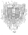
Figure 3 shows an enlarged longitudinal section, with parts removed for clarity, of a valve set to the second stable position and in accordance with a second embodiment of the present invention; -
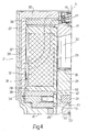
Figure 4 shows a larger-scale longitudinal section, with parts removed for clarity, of a detail inFigure 1 . - With reference to
Figures 1 and2 , number 1 indicates as a whole a liquid flow on-off valve with a bistableelectromagnetic control assembly 2, so that valve 1 is kept open (first stable position,Figure 2 ) or closed (second stable position,Figure 1 ) with no electric power toelectromagnetic control assembly 2. - Valve 1 extends along an axis A, and comprises a
valve body 3; acover 4 fitted tovalve body 3; ashutter 5 movable along axis A; and amembrane 6 fixed tovalve body 3 andshutter 5. Shutter 5 is integral with a cup-shaped body 7 housingelectromagnetic control assembly 2, which therefore moves along axis A together withshutter 5. -
Valve body 3 comprises alateral wall 8; a bottom wall 9 (the terms "lateral" and "bottom" as used herein refer solely to the way in which the valve is shown in the accompanying drawings, it being understood that valve 1 may be oriented any way); and atube 10 projecting frombottom wall 9..Openings 11 are formed inbottom wall 9 and define aliquid inlet channel 12, whiletube 10 defines anoutlet channel 13.Lateral wall 8 is closed bycover 4, which defines, insidevalve body 3, agap 14 communicating at all times withinlet channel 12, regardless of the operating position of valve 1. Acompression spring 15 is located betweencover 4 andassembly 2, and pusheselectromagnetic control assembly 2, cup-shaped body 7 andshutter 5, andmembrane 6 onto the end oftube 10 to prevent liquid flow frominlet channel 12 to outlet channel 13 (Figure 1 ).Membrane 6 is annular, and comprises anouter seal 16 fixed tovalve body 3, betweenlateral wall 8 andbottom wall 9; and aninner seal 17 fixed toshutter 5 and, in the example shown, housed inside acavity 18 formed betweenshutter 5 and cup-shaped body 7, which in fact are formed in one piece.Membrane 6 also has threeholes 19, which are equally spaced about axis A, are located atcorresponding openings 11 at one end, and are connected to one another, at the other end, by an annular channel formed inmembrane 6. The annular channel is connected to achannel 20 formed in cup-shaped body 7 and in turn connected togap 14, so thatgap 14 invalve body 3 communicates withinlet channel 12, regardless of the operating position.of valve 1. -
Shutter 5 comprises acylindrical body 21, which slides along axisA inside tube 10; and acentral tube 22 defining achannel 23, which can be selectively opened to connectoutlet channel 13 togap 14, and therefore to inletchannel 12. In other words,holes 19,channel 20,gap 14, andchannel 23 define an auxiliary channel connectinginlet channel 12 andoutlet channel 13, and which can be cut off selectively by anauxiliary shutter 24 controlled byelectromagnetic control assembly 2. - With reference to
Figure 4 ,auxiliary shutter 24 is integral with anarmature 25 movable along axis A and forming part ofelectromagnetic control assembly 2, which comprises acylindrical body 26, of axis A, having two outerannular flanges Cylindrical body 26 is made of insulating material, and is fitted to cup-shaped body 7 with aseal 29 and resin 30 to isolate from the liquid acompartment 31 housing acoil 32, ayoke 33, and apermanent magnet 34.Electromagnetic control assembly 2 also comprises acore 35 fixed insidecylindrical body 26 and having aface 36 located along axis A, betweenflanges Core 35 andarmature 25 are coaxial and housed insidecylindrical body 26.Coil 32 surroundscylindrical body 26, and is housed betweenflanges cylindrical wall 37 which forms part ofyoke 33. In addition tocylindrical wall 37,yoke 33 also comprises aring 38 located atflange 27, on the opposite side tocoil 32, and contacting one end ofcylindrical wall 37; aring 39 contactingflange 28 and the opposite end ofcylindrical wall 37; and aring 40 surroundingcylindrical body 26 and separated fromring 39 bypermanent magnet 34.Rings cylindrical faces core 35 directly, while magnetic poles P2, P3 contact the outer face ofcylindrical body 26. Magnetic poles P1, P2, P3 are arranged successively along axis A in the direction fromcore 35 toarmature 25. More specifically, the first magnetic pole P1 facescore 35; the second magnetic pole P2 facesarmature 25; and the third magnetic poleP3 faces tube 22, and neithercore 35 norarmature 25. The distance between magnetic poles P2 and P3 is much smaller than that between magnetic poles P1 and P2. - The exact position of second magnetic pole P2 along axis A is substantially selected as a function of the length of
armature 25 along axis A, and so that, whenarmature 25 is in the first stable position (Figure 2 ), the magnetic flux through second magnetic pole P2 is negligible with respect to the magnetic flux generated bypermanent magnet 34 through first and third magnetic pole P1 and P3; and, whenarmature 25 is in the second stable position (Figure 1 ), the magnetic flux through first magnetic pole P1 is negligible with respect to the magnetic flux generated by the permanent magnet through second and third magnetic pole P2 and P3. -
Permanent magnet 34 is also in the form of a ring (bored disk), is substantially the same thickness asrings rings ring 39. - Valve 1 in
Figure 1 is shown in a second stable position, in which flow betweeninlet channel 12 andoutlet channel 13 is cut off byshutter 5; and flow along the auxiliary channel - defined bygap 14,holes 19 in the membrane,channel 20, and channel 23 - is also cut off byauxiliary shutter 24, which is pressed ontotube 22 by the magnetic flux generated bypermanent magnet 24 through magnetic poles P2 and P3 and acting onarmature 25. By virtue ofholes 19 connectinggap 14 andinlet channel 12, the pressure of the liquid ininlet channel 12 equals the pressure of the liquid ingap 14, and, by virtue of the difference between the surfaces on different sides ofmembrane 6, keepsshutter 5 in the second stable position. - When a pulse is transmitted to
coil 32 to generate magnetic flux concordant with that generated bypermanent magnet 34, the total magnetic flux travels through poles P1 and P3, and the flux through magnetic pole P2 becomes negligible. Consequently,armature 25 adheres tocore 35, andauxiliary shutter 24 is detached fromtube 22 and connectsgap 14 tooutlet channel 13, so that the pressure ingap 14 falls before the pressure ininlet channel 12, and the liquid acting onmembrane 6 overcomes the force ofspring 15 and raises cup-shaped body 7 ofshutter 5 andelectromagnetic assembly 2. - At the end of the pulse to coil 32, which is intrinsically instantaneous,
armature 25 is held contactingcore 35 by the magnetic flux generated bypermanent magnet 34, and which predominantly closes through magnetic poles P1 and P3, whereas the magnetic flux through magnetic pole P2 is negligible. Valve 1 is therefore retained in the first stable position solely by the action ofpermanent magnet 34. - At this point, a pulse transmitted to
coil 32, to generate magnetic flux discordant with respect to that generated bypermanent magnet 34, produces magnetic flux through magnetic poles P1 and P2 to detacharmature 25 fromcore 35, whilepermanent magnet 34 produces magnetic flux between poles P2 and P3 to pressarmature 25 andauxiliary shutter 24 ontotube 22. At the end of the pulse, the predominant magnetic flux is that acting between poles P2 and P3, so thatauxiliary shutter 24 is closed, thus closing and maintaining the second stable position of valve 1. - In the
Figure 3 embodiment, the same reference numbers as in the above description of the first embodiment are used to indicate the same component parts, except for those differing substantially from the first embodiment. Valve 1 inFigure 3 substantially differs from theFigure 1 valve as regards certain parts ofelectromagnetic control assembly 2. More specifically,permanent magnet 34 is replaced by two annularpermanent magnets 44 and 45 connected along axis A. Magnetic pole P3 is defined by an L-section ring 46 substantially comprising aportion 47 perpendicular to axis A, and aportion 48 coaxial with axis A and having a face 49 extending about axis A and defining third magnetic pole P3. The magnetic flux generated by the twopermanent magnets 44 and 45 is greater than that generated by onemagnet 34.
Claims (15)
- A liquid flow on-off valve with a bistable electromagnetic control assembly (2), the valve comprising an auxiliary channel (14, 19, 20, 23); an auxiliary shutter (24) activated by the electromagnetic control assembly (2) to selectively cut off flow along the auxiliary channel (14, 19, 20, 23); the electromagnetic control assembly (2), in turn comprising a yoke (33); a coil (32) cooperating with said yoke (33); a core (35) inside said coil (32); a permanent magnet (34; 44, 45) cooperating with said yoke (33); and an armature (25) movable, along an axis (A), between a first stable position contacting said core (35), and a second stable position wherein said armature (25) is a given distance from said core (35); the yoke (33) comprising a first portion (37, 38, 39) fitted about said coil (32) and defining, in use, a first and a second magnetic pole (P1, P2); and a second portion (40; 46) separated from the first portion by the permanent magnet (34; 44, 45) and defining a third magnetic pole (P3); the first, second, and third magnetic pole (P1, P2, P3) being arranged successively along said axis (A), from the core (35) towards the armature (25); the valve being characterized in that the first magnetic pole (P1) faces the core (35), the second magnetic pole (P2) faces the armature (25), and the third magnetic pole (P3) faces neither the core (35) nor the armature (25) so that the first and second stable position are maintained solely by the magnetic flux generated by the permanent magnet (34; 44, 45) and conducted selectively through the yoke (33), the core (35), and the armature (25) as a function of the position of the armature (25).
- A valve as claimed in Claim 1, characterized in that the permanent magnet (34; 44, 45), the core (35), the armature (25), and the yoke (33) are so designed that the magnetic flux is guided along a first path, when the armature (25) is in the first stable position, the first path of the magnetic flux maintaining the armature (25) in the first stable position, and is guided along a second path, when the armature (25) is in the second stable position, the second path of the magnetic flux maintaining the armature (25) in the second stable position.
- A valve as claimed in Claim 1 or 2, characterized by having no springs for determining either the first or second stable position.
- A valve as claimed in any one of the foregoing Claims, characterized in that the permanent magnet (34; 44, 45) is substantially on a level with the auxiliary shutter (24) along said axis (A); the auxiliary shutter (24) being located at the free end of the armature (25).
- A valve as claimed in any one of the foregoing Claims, characterized in that the core (35) is of a length, along said axis (A), greater than the length of the armature (25) along said axis (A).
- A valve as claimed in Claim 5, characterized in that the length of the core (35) is substantially one and a half times the length of the armature (25) along said axis (A).
- A valve as claimed in any one of the foregoing Claims, characterized in that the distance between the second and third magnetic pole (P2, P3) is much smaller than the distance between the first and second magnetic pole (P1, P2).
- A valve as claimed in any one of the foregoing Claims, characterized in that the position of the first and second magnetic pole (P1, P2) along said axis (A) is selected as a function of the length of the armature along said axis (A), and so that, when the armature (25) is in the first stable position, the magnetic flux through the second magnetic pole (P2) is negligible with respect to the magnetic flux through the first and third magnetic pole (P1, P3), and, when the armature (25) is in the second stable position, the magnetic flux through the first magnetic pole (P1) is negligible with respect to the magnetic flux through the second and third magnetic pole (P2, P3).
- A valve as claimed in any one the foregoing Claims, characterized in that the first, second, and third magnetic poles (P1, P2, P3) are defined by inner faces (41, 42, 43; 41, 42, 49) of respective first, second, and third rings (38, 39, 40; 38, 39, 46).
- A valve as claimed in Claim 9 characterized in that the third ring (40; 46) has an outside diameter smaller than the outside diameter of the first and second ring (38, 39).
- A valve as claimed in Claim 9 or 10, characterized in that the permanent magnet (34) is defined by a magnetic ring gripped between the second and third ring (39, 40).
- A valve as claimed in Claim 9 or 10, characterized in that the permanent magnet (44, 45) comprises two magnetic rings gripped between the second and third ring (39, 46).
- A valve as claimed in Claim 11 or 12, characterized in that the magnetic ring has an outside diameter equal to the outside diameter of the first and second ring (38, 39).
- A valve as claimed in Claim 11 or 12, characterized in that the magnetic ring has an inside diameter much smaller than the inside diameters of the first, second, and third ring (38, 39, 40; 38, 39, 46).
- A valve as claimed in Claim 9, characterized in that the third ring (46) has an L-shaped cross section.
Applications Claiming Priority (2)
| Application Number | Priority Date | Filing Date | Title |
|---|---|---|---|
| IT001404A ITMI20051404A1 (en) | 2005-07-21 | 2005-07-21 | LIQUID FLOW INTERCEPT VALVE WITH BI-STABLE TYPE ELECTROMAGNET GROUP |
| PCT/EP2006/064477 WO2007010026A1 (en) | 2005-07-21 | 2006-07-20 | Liquid flow valve with a bistable electromagnetic control assembly |
Publications (2)
| Publication Number | Publication Date |
|---|---|
| EP1907737A1 EP1907737A1 (en) | 2008-04-09 |
| EP1907737B1 true EP1907737B1 (en) | 2009-05-27 |
Family
ID=37054518
Family Applications (1)
| Application Number | Title | Priority Date | Filing Date |
|---|---|---|---|
| EP06777871A Active EP1907737B1 (en) | 2005-07-21 | 2006-07-20 | Liquid flow valve with a bistable electromagnetic control assembly |
Country Status (7)
| Country | Link |
|---|---|
| EP (1) | EP1907737B1 (en) |
| CN (1) | CN101258352A (en) |
| AT (1) | ATE432437T1 (en) |
| DE (1) | DE602006007004D1 (en) |
| IL (1) | IL188888A0 (en) |
| IT (1) | ITMI20051404A1 (en) |
| WO (1) | WO2007010026A1 (en) |
Families Citing this family (10)
| Publication number | Priority date | Publication date | Assignee | Title |
|---|---|---|---|---|
| GB0919645D0 (en) * | 2009-11-10 | 2009-12-23 | Sentec Ltd | Flux switched fuel injector |
| IT1403285B1 (en) * | 2010-12-23 | 2013-10-17 | Rpe Srl | GROUP DISPENSER OF A LIQUID OR A MIXTURE OF LIQUIDS |
| GB201207289D0 (en) * | 2011-06-14 | 2012-06-06 | Sentec Ltd | Flux switch actuator |
| IL217006A0 (en) * | 2011-12-15 | 2012-02-29 | Haim Morgenstein | An apparatus and method for generating electricity in hydraulic systems |
| DE102012221047A1 (en) * | 2012-11-19 | 2014-05-22 | Hansgrohe Se | Valve head for a sanitary fitting |
| CN105179791B (en) * | 2015-08-25 | 2016-06-01 | 北京控制工程研究所 | A Monostable Axial Flow Solenoid Valve Based on Uncoupled Permanent Magnet Bias |
| CN106401457B (en) * | 2016-11-14 | 2018-07-10 | 郑州神利达钻采设备有限公司 | Hydrodynamic force oil-well rig and its method of work |
| US20180313463A1 (en) * | 2017-04-26 | 2018-11-01 | Robertshaw Controls Company | Pilot operated valve with extended insert |
| FR3087935B1 (en) * | 2018-10-26 | 2021-05-14 | Moving Magnet Tech | BISTABLE SINGLE POLE BALLISTIC ACTUATOR |
| IT202000000907A1 (en) * | 2020-01-17 | 2021-07-17 | Seprio Plast Zn S R L | SAFETY SOLENOID VALVE FOR FLUIDS WITH CONTROLLED OPENING |
Family Cites Families (5)
| Publication number | Priority date | Publication date | Assignee | Title |
|---|---|---|---|---|
| US4948090A (en) * | 1989-09-27 | 1990-08-14 | Chen Chge San | Induction type automatic-controlled fluid faucet |
| IT1271264B (en) * | 1994-12-14 | 1997-05-27 | Claber Spa | SOLENOID VALVE FOR IRRIGATION UNITS |
| EP0791939B1 (en) * | 1995-09-08 | 2003-08-13 | Toto Ltd. | Solenoid and solenoid valve |
| DE19958888A1 (en) * | 1999-12-07 | 2001-06-13 | Sheng Chih Sheng | Bidirectional electro magnetic linear actuator for valve, has armature located in exciting coil with permanent magnets for providing holding force at end sections |
| EP1416207A1 (en) * | 2002-10-30 | 2004-05-06 | Rpe S.R.L. | Membrane valve with a pilot solenoid valve |
-
2005
- 2005-07-21 IT IT001404A patent/ITMI20051404A1/en unknown
-
2006
- 2006-07-20 AT AT06777871T patent/ATE432437T1/en not_active IP Right Cessation
- 2006-07-20 DE DE602006007004T patent/DE602006007004D1/en active Active
- 2006-07-20 EP EP06777871A patent/EP1907737B1/en active Active
- 2006-07-20 WO PCT/EP2006/064477 patent/WO2007010026A1/en active Application Filing
- 2006-07-20 CN CNA2006800323355A patent/CN101258352A/en active Pending
-
2008
- 2008-01-20 IL IL188888A patent/IL188888A0/en unknown
Also Published As
| Publication number | Publication date |
|---|---|
| ITMI20051404A1 (en) | 2007-01-22 |
| IL188888A0 (en) | 2008-04-13 |
| ATE432437T1 (en) | 2009-06-15 |
| EP1907737A1 (en) | 2008-04-09 |
| DE602006007004D1 (en) | 2009-07-09 |
| CN101258352A (en) | 2008-09-03 |
| WO2007010026A1 (en) | 2007-01-25 |
Similar Documents
| Publication | Publication Date | Title |
|---|---|---|
| EP1907737B1 (en) | Liquid flow valve with a bistable electromagnetic control assembly | |
| US5497135A (en) | Bistable electromagnet, particularly an electromagnetic valve | |
| CN109672963B (en) | Acoustic channel element with valve and transducer with acoustic channel element | |
| EP2567131B1 (en) | Electromagnetically operated switching devices and methods of actuation thereof | |
| EP3919796B1 (en) | Solenoid valve for gas | |
| US4506701A (en) | Solenoid-operated valve for selecting one of two pressure sources | |
| US6489870B1 (en) | Solenoid with improved pull force | |
| US8567440B2 (en) | Solenoid operated valve | |
| WO2002043083A2 (en) | Latching solenoid with improved pull force | |
| JP6258008B2 (en) | solenoid valve | |
| KR101492532B1 (en) | Solenoid valve | |
| US20020000530A1 (en) | Proportional solenoid-controlled fluid valve assembly without non-magnetic alignment support element | |
| JP2013217465A (en) | Solenoid valve | |
| US8413950B2 (en) | Actuating solenoid and non-stick disk | |
| JP4207209B2 (en) | solenoid valve | |
| CN102446613A (en) | Solenoid device and driver assistance device | |
| JP2015094414A (en) | Electromagnetic valve | |
| US10916398B2 (en) | Electromagnetic relay | |
| US7145424B2 (en) | Solenoid assembly | |
| JPH08200537A (en) | Solenoid | |
| JP2897386B2 (en) | Solenoid switching valve | |
| JPH10238648A (en) | Solenoid valve | |
| JP3251085B2 (en) | solenoid valve | |
| JP7455053B2 (en) | solenoid valve | |
| JP4482402B2 (en) | Solenoid valve device |
Legal Events
| Date | Code | Title | Description |
|---|---|---|---|
| PUAI | Public reference made under article 153(3) epc to a published international application that has entered the european phase |
Free format text: ORIGINAL CODE: 0009012 |
|
| 17P | Request for examination filed |
Effective date: 20080131 |
|
| AK | Designated contracting states |
Kind code of ref document: A1 Designated state(s): AT BE BG CH CY CZ DE DK EE ES FI FR GB GR HU IE IS IT LI LT LU LV MC NL PL PT RO SE SI SK TR |
|
| GRAP | Despatch of communication of intention to grant a patent |
Free format text: ORIGINAL CODE: EPIDOSNIGR1 |
|
| DAX | Request for extension of the european patent (deleted) | ||
| GRAS | Grant fee paid |
Free format text: ORIGINAL CODE: EPIDOSNIGR3 |
|
| GRAA | (expected) grant |
Free format text: ORIGINAL CODE: 0009210 |
|
| AK | Designated contracting states |
Kind code of ref document: B1 Designated state(s): AT BE BG CH CY CZ DE DK EE ES FI FR GB GR HU IE IS IT LI LT LU LV MC NL PL PT RO SE SI SK TR |
|
| REG | Reference to a national code |
Ref country code: GB Ref legal event code: FG4D |
|
| REG | Reference to a national code |
Ref country code: CH Ref legal event code: EP |
|
| REG | Reference to a national code |
Ref country code: IE Ref legal event code: FG4D |
|
| REF | Corresponds to: |
Ref document number: 602006007004 Country of ref document: DE Date of ref document: 20090709 Kind code of ref document: P |
|
| PG25 | Lapsed in a contracting state [announced via postgrant information from national office to epo] |
Ref country code: PT Free format text: LAPSE BECAUSE OF FAILURE TO SUBMIT A TRANSLATION OF THE DESCRIPTION OR TO PAY THE FEE WITHIN THE PRESCRIBED TIME-LIMIT Effective date: 20090927 Ref country code: FI Free format text: LAPSE BECAUSE OF FAILURE TO SUBMIT A TRANSLATION OF THE DESCRIPTION OR TO PAY THE FEE WITHIN THE PRESCRIBED TIME-LIMIT Effective date: 20090527 Ref country code: AT Free format text: LAPSE BECAUSE OF FAILURE TO SUBMIT A TRANSLATION OF THE DESCRIPTION OR TO PAY THE FEE WITHIN THE PRESCRIBED TIME-LIMIT Effective date: 20090527 Ref country code: LT Free format text: LAPSE BECAUSE OF FAILURE TO SUBMIT A TRANSLATION OF THE DESCRIPTION OR TO PAY THE FEE WITHIN THE PRESCRIBED TIME-LIMIT Effective date: 20090527 |
|
| NLV1 | Nl: lapsed or annulled due to failure to fulfill the requirements of art. 29p and 29m of the patents act | ||
| PG25 | Lapsed in a contracting state [announced via postgrant information from national office to epo] |
Ref country code: SE Free format text: LAPSE BECAUSE OF FAILURE TO SUBMIT A TRANSLATION OF THE DESCRIPTION OR TO PAY THE FEE WITHIN THE PRESCRIBED TIME-LIMIT Effective date: 20090827 Ref country code: PL Free format text: LAPSE BECAUSE OF FAILURE TO SUBMIT A TRANSLATION OF THE DESCRIPTION OR TO PAY THE FEE WITHIN THE PRESCRIBED TIME-LIMIT Effective date: 20090527 Ref country code: IS Free format text: LAPSE BECAUSE OF FAILURE TO SUBMIT A TRANSLATION OF THE DESCRIPTION OR TO PAY THE FEE WITHIN THE PRESCRIBED TIME-LIMIT Effective date: 20090927 Ref country code: SI Free format text: LAPSE BECAUSE OF FAILURE TO SUBMIT A TRANSLATION OF THE DESCRIPTION OR TO PAY THE FEE WITHIN THE PRESCRIBED TIME-LIMIT Effective date: 20090527 Ref country code: LV Free format text: LAPSE BECAUSE OF FAILURE TO SUBMIT A TRANSLATION OF THE DESCRIPTION OR TO PAY THE FEE WITHIN THE PRESCRIBED TIME-LIMIT Effective date: 20090527 Ref country code: NL Free format text: LAPSE BECAUSE OF FAILURE TO SUBMIT A TRANSLATION OF THE DESCRIPTION OR TO PAY THE FEE WITHIN THE PRESCRIBED TIME-LIMIT Effective date: 20090527 |
|
| PG25 | Lapsed in a contracting state [announced via postgrant information from national office to epo] |
Ref country code: ES Free format text: LAPSE BECAUSE OF FAILURE TO SUBMIT A TRANSLATION OF THE DESCRIPTION OR TO PAY THE FEE WITHIN THE PRESCRIBED TIME-LIMIT Effective date: 20090907 Ref country code: RO Free format text: LAPSE BECAUSE OF FAILURE TO SUBMIT A TRANSLATION OF THE DESCRIPTION OR TO PAY THE FEE WITHIN THE PRESCRIBED TIME-LIMIT Effective date: 20090527 Ref country code: CZ Free format text: LAPSE BECAUSE OF FAILURE TO SUBMIT A TRANSLATION OF THE DESCRIPTION OR TO PAY THE FEE WITHIN THE PRESCRIBED TIME-LIMIT Effective date: 20090527 Ref country code: EE Free format text: LAPSE BECAUSE OF FAILURE TO SUBMIT A TRANSLATION OF THE DESCRIPTION OR TO PAY THE FEE WITHIN THE PRESCRIBED TIME-LIMIT Effective date: 20090527 Ref country code: DK Free format text: LAPSE BECAUSE OF FAILURE TO SUBMIT A TRANSLATION OF THE DESCRIPTION OR TO PAY THE FEE WITHIN THE PRESCRIBED TIME-LIMIT Effective date: 20090527 |
|
| PG25 | Lapsed in a contracting state [announced via postgrant information from national office to epo] |
Ref country code: SK Free format text: LAPSE BECAUSE OF FAILURE TO SUBMIT A TRANSLATION OF THE DESCRIPTION OR TO PAY THE FEE WITHIN THE PRESCRIBED TIME-LIMIT Effective date: 20090527 Ref country code: MC Free format text: LAPSE BECAUSE OF NON-PAYMENT OF DUE FEES Effective date: 20090731 Ref country code: BE Free format text: LAPSE BECAUSE OF FAILURE TO SUBMIT A TRANSLATION OF THE DESCRIPTION OR TO PAY THE FEE WITHIN THE PRESCRIBED TIME-LIMIT Effective date: 20090527 |
|
| PG25 | Lapsed in a contracting state [announced via postgrant information from national office to epo] |
Ref country code: BG Free format text: LAPSE BECAUSE OF FAILURE TO SUBMIT A TRANSLATION OF THE DESCRIPTION OR TO PAY THE FEE WITHIN THE PRESCRIBED TIME-LIMIT Effective date: 20090827 |
|
| PLBE | No opposition filed within time limit |
Free format text: ORIGINAL CODE: 0009261 |
|
| STAA | Information on the status of an ep patent application or granted ep patent |
Free format text: STATUS: NO OPPOSITION FILED WITHIN TIME LIMIT |
|
| REG | Reference to a national code |
Ref country code: FR Ref legal event code: ST Effective date: 20100331 |
|
| REG | Reference to a national code |
Ref country code: IE Ref legal event code: MM4A |
|
| PG25 | Lapsed in a contracting state [announced via postgrant information from national office to epo] |
Ref country code: FR Free format text: LAPSE BECAUSE OF NON-PAYMENT OF DUE FEES Effective date: 20090731 |
|
| 26N | No opposition filed |
Effective date: 20100302 |
|
| PG25 | Lapsed in a contracting state [announced via postgrant information from national office to epo] |
Ref country code: IE Free format text: LAPSE BECAUSE OF NON-PAYMENT OF DUE FEES Effective date: 20090720 |
|
| PG25 | Lapsed in a contracting state [announced via postgrant information from national office to epo] |
Ref country code: GR Free format text: LAPSE BECAUSE OF FAILURE TO SUBMIT A TRANSLATION OF THE DESCRIPTION OR TO PAY THE FEE WITHIN THE PRESCRIBED TIME-LIMIT Effective date: 20090828 |
|
| REG | Reference to a national code |
Ref country code: CH Ref legal event code: PL |
|
| GBPC | Gb: european patent ceased through non-payment of renewal fee |
Effective date: 20100720 |
|
| PG25 | Lapsed in a contracting state [announced via postgrant information from national office to epo] |
Ref country code: LI Free format text: LAPSE BECAUSE OF NON-PAYMENT OF DUE FEES Effective date: 20100731 Ref country code: CH Free format text: LAPSE BECAUSE OF NON-PAYMENT OF DUE FEES Effective date: 20100731 Ref country code: LU Free format text: LAPSE BECAUSE OF NON-PAYMENT OF DUE FEES Effective date: 20090720 |
|
| PG25 | Lapsed in a contracting state [announced via postgrant information from national office to epo] |
Ref country code: HU Free format text: LAPSE BECAUSE OF FAILURE TO SUBMIT A TRANSLATION OF THE DESCRIPTION OR TO PAY THE FEE WITHIN THE PRESCRIBED TIME-LIMIT Effective date: 20091128 |
|
| PG25 | Lapsed in a contracting state [announced via postgrant information from national office to epo] |
Ref country code: GB Free format text: LAPSE BECAUSE OF NON-PAYMENT OF DUE FEES Effective date: 20100720 |
|
| PG25 | Lapsed in a contracting state [announced via postgrant information from national office to epo] |
Ref country code: TR Free format text: LAPSE BECAUSE OF FAILURE TO SUBMIT A TRANSLATION OF THE DESCRIPTION OR TO PAY THE FEE WITHIN THE PRESCRIBED TIME-LIMIT Effective date: 20090527 |
|
| PG25 | Lapsed in a contracting state [announced via postgrant information from national office to epo] |
Ref country code: CY Free format text: LAPSE BECAUSE OF FAILURE TO SUBMIT A TRANSLATION OF THE DESCRIPTION OR TO PAY THE FEE WITHIN THE PRESCRIBED TIME-LIMIT Effective date: 20090527 |
|
| P01 | Opt-out of the competence of the unified patent court (upc) registered |
Effective date: 20230418 |
|
| PGFP | Annual fee paid to national office [announced via postgrant information from national office to epo] |
Ref country code: DE Payment date: 20240730 Year of fee payment: 19 |
|
| PGFP | Annual fee paid to national office [announced via postgrant information from national office to epo] |
Ref country code: IT Payment date: 20240704 Year of fee payment: 19 |