EP2247493B1 - Vehicle coupling for producing a mechanical bond between a first and a second vehicle - Google Patents
Vehicle coupling for producing a mechanical bond between a first and a second vehicle Download PDFInfo
- Publication number
- EP2247493B1 EP2247493B1 EP09704350A EP09704350A EP2247493B1 EP 2247493 B1 EP2247493 B1 EP 2247493B1 EP 09704350 A EP09704350 A EP 09704350A EP 09704350 A EP09704350 A EP 09704350A EP 2247493 B1 EP2247493 B1 EP 2247493B1
- Authority
- EP
- European Patent Office
- Prior art keywords
- vehicle
- coupling
- metal foam
- coupling according
- vehicle coupling
- Prior art date
- Legal status (The legal status is an assumption and is not a legal conclusion. Google has not performed a legal analysis and makes no representation as to the accuracy of the status listed.)
- Active
Links
Images


Classifications
-
- B—PERFORMING OPERATIONS; TRANSPORTING
- B62—LAND VEHICLES FOR TRAVELLING OTHERWISE THAN ON RAILS
- B62D—MOTOR VEHICLES; TRAILERS
- B62D53/00—Tractor-trailer combinations; Road trains
- B62D53/04—Tractor-trailer combinations; Road trains comprising a vehicle carrying an essential part of the other vehicle's load by having supporting means for the front or rear part of the other vehicle
- B62D53/08—Fifth wheel traction couplings
-
- B—PERFORMING OPERATIONS; TRANSPORTING
- B62—LAND VEHICLES FOR TRAVELLING OTHERWISE THAN ON RAILS
- B62D—MOTOR VEHICLES; TRAILERS
- B62D29/00—Superstructures, understructures, or sub-units thereof, characterised by the material thereof
- B62D29/001—Superstructures, understructures, or sub-units thereof, characterised by the material thereof characterised by combining metal and synthetic material
- B62D29/002—Superstructures, understructures, or sub-units thereof, characterised by the material thereof characterised by combining metal and synthetic material a foamable synthetic material or metal being added in situ
-
- B—PERFORMING OPERATIONS; TRANSPORTING
- B62—LAND VEHICLES FOR TRAVELLING OTHERWISE THAN ON RAILS
- B62D—MOTOR VEHICLES; TRAILERS
- B62D53/00—Tractor-trailer combinations; Road trains
- B62D53/04—Tractor-trailer combinations; Road trains comprising a vehicle carrying an essential part of the other vehicle's load by having supporting means for the front or rear part of the other vehicle
- B62D53/08—Fifth wheel traction couplings
- B62D53/0885—Comprising devices to limit or to compensate for wear or excessive play; Lubricating, shock absorbing, bearing devices, or the like
Definitions
- the invention relates to a vehicle coupling for establishing a mechanical connection between a first and a second vehicle, wherein the vehicle coupling comprises a coupling body.
- vehicle coupling is well known.
- the coupling body and the components cooperating therewith are usually manufactured by casting from steel or ductile iron or also welded from sheet metal parts.
- the resulting robust construction is necessary for the high expected operating forces to avoid deformation and to ensure maximum wear protection.
- these previously applied constructions are disadvantageous in that the weight of the vehicle clutch is very high, which in turn adversely affects the curb weight of the vehicle, so that at a given maximum permissible total weight a correspondingly lower payload is available.
- Another disadvantage of cast components is the risk of formation of inclusions and voids, particularly in areas of locally required metal buildup.
- the invention has the object, a vehicle clutch with a comparison with known
- the object is achieved with a vehicle clutch, wherein at least one structural region of the coupling body is formed from a metal foam.
- the main advantage of the metal foam lies in the very high strength at a significantly reduced density compared to steel.
- the metal foam is made from a blowing agent and a metal powder added thereto, wherein the metal powder is usually made of aluminum or steel. After combining and mixing the blowing agent with the metal powder, a first shaping process followed by foaming follows. Due to the foam structure results in an extremely low volume density with only slightly reduced strength of the metal foam.
- the coupling body comprises a coupling plate of a fifth wheel.
- the coupling body may also be formed from a coupling jaw of a trailer or bolt coupling.
- the metal foam has a coating wholly or partly.
- the metal coupling made of metal foam or the correspondingly formed areas have a comparatively rough surface, which can be smoothed by a coating.
- the coating can increase the corrosion resistance.
- the coating can be formed, for example, from a filling paint.
- an encapsulation or foam coating with a plastic. This can be partially applied to the entire vehicle clutch or partially. In particular, individual components may be completely encapsulated with the coating.
- the structural region is formed in a sandwich construction.
- the sandwich construction is a construction in which several layers of different properties are embedded in a material.
- the sandwich design refers to a form of lightweight construction, in which the components consist of force-absorbing cover layers, which are held by a relatively soft, usually lightweight, core material at a distance. These parts are very flexible and bulky at low weight. The core material transmits occurring shear forces and supports the cover layers.
- the metal foam should form the core, which is connected to at least one cover layer of steel and / or plastic and / or aluminum. It should be used at locations where a closed-pore surface is needed, for example, to achieve low coefficients of friction, a conventional steel sheet or possibly also a plastic layer used.
- the structural region advantageously comprises a metal foam support element formed on the coupling body.
- a support element is understood to be a rib structure reinforcing the coupling plate or the coupling jaw. In a fifth wheel, this is arranged on the underside of the clutch plate, with a coupling jaw on the outside of the conically widened entry opening.
- the support element is connected by an adhesive layer to the coupling body.
- the adhesive layer can be made by means of a plastic compound, which is preferably fiber-reinforced.
- thermoplastics or thermosets Suitable materials for the plastic composition are thermoplastics or thermosets.
- a thermoplastic deforms when heated and retains its shape when cooled.
- the best known thermoplastics are polypropylene, polyethylene, polyester, polyvinyl chloride and polyamide.
- Thermosets also called duromers, are plastics that can not be deformed after they have hardened.
- Thermosets are hard, glass-like polymer materials that are three-dimensionally firmly cross-linked by chemical valence bonds. The crosslinking takes place during the mixing of precursors with branching points and is thermally activated either at room temperature with the aid of catalysts chemically or at high temperatures.
- a plastic foam can also be used as the plastic compound.
- a metal foam is particularly well suited for creating an adhesive layer.
- the metal foam is arranged in a lying in the power flow portion of the coupling body according to a preferred embodiment.
- the metal foam is formed with a bearing point and / or mounting hole.
- the bearings are on a fifth wheel at opposite lateral positions for supporting the coupling plate to underlying bearing blocks arranged.
- the mounting holes can be formed for example as a threaded insert part.
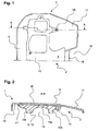
- FIG. 1 shows a bottom view of a coupling plate 4 of a fifth wheel, on which the invention is explained representative of all coupling body 1.
- the clutch plate 4 has on its rear side 15 a retraction opening 16, in which a not shown kingpin of a trailer can be retracted in the usual manner in the fifth wheel.
- the retraction opening 16 is bounded on both sides by a coupling horn 17, wherein in the illustration of FIG. 1 only the right in the direction of travel coupling horn 17 can be seen.
- the support element 10 comprises a substantially horizontally extending base plate 10a, are formed on the vertical wall portions 10b.
- FIG. 2 can be removed, the support member 10 is bonded by means of an adhesive layer 11 under the coupling plate 4.
- the adhesive layer 11 is essentially limited to the contact region of the support element 10 to the coupling plate 4.
- the metal foam 3 of the support element 10 allows a particularly simple introduction, for example, a mounting hole 14. In These can then be screwed to the coupling body 1 further units or components of the closure mechanism.
- FIG. 3 shows a further embodiment in which the support member 10 is provided in addition to the adhesive layer 11 with a coating 5.
- the coating 5 is applied as a foam 6 and surrounds the support member 10 almost completely. Only an area around the mounting hole 14 is excluded from the foam 6, so that there the metal foam 3 forms an externally accessible surface. This surface made of metal foam 3 allows higher surface pressures for the components to be screwed to the fastening bore 14.
- FIG. 4 a further embodiment with a coupling plate 4 in a sandwich construction 7 is shown.
- the upper side 20 of the coupling plate 4 has, as the upper cover layer 9a, a metal plate in order to ensure a resistant bearing region 18 with low coefficients of friction.
- a support plate, not shown on it, can thus slide on the bearing area 18 with little wear.
- the metal foam 3 was introduced directly as the core 8 of the sandwich construction, which forms a frictional connection with the cover layer 9a after curing.
- the sandwich construction 7 has a lower cover layer 9b, which likewise adheres directly to the metal foam 3.
- the lower cover layer 9b may in particular be a plastic layer.
- the lower cover layer 9b is connected via an adhesive layer 11 with the additional support element 10 made of metal foam 3. Also at In this embodiment, a completely cast-in or foam-fitted attachment of the support element 10 is possible.
- FIG. 5 shows an alternative attachment of the support member 10 to the coupling plate 4 by means of a plurality of connecting elements, of which screws 12 are exemplified. These enforced the coupling plate 4 in the vertical direction completely and are held stationary on the bottom 19 with a nut.
- an adhesive layer 11 can be completely dispensed with.
Abstract
Description
Die Erfindung betrifft eine Fahrzeugkupplung zum Herstellen einer mechanischen Verbindung zwischen einem ersten und einem zweiten Fahrzeug, wobei die Fahrzeugkupplung einen Kupplungskörper umfasst. Eine derartige Fahrzeugkupplung ist allgemein bekannt.The invention relates to a vehicle coupling for establishing a mechanical connection between a first and a second vehicle, wherein the vehicle coupling comprises a coupling body. Such a vehicle coupling is well known.
Der Kupplungskörper und die damit zusammenwirkenden Bauteile werden üblicherweise gießtechnisch aus Stahl- oder Sphäroguss hergestellt oder auch aus Blechteilen geschweißt. Die daraus resultierende robuste Bauweise ist bei den hohen zu erwartenden Betriebskräften notwendig, um Verformungen zu vermeiden und einen maximalen Verschleißschutz zu gewährleisten. Diese bisher angewandten Bauweisen sind jedoch insofern nachteilig, als dass das Eigengewicht der Fahrzeugkupplung sehr hoch ist, was sich wiederum nachteilig auf das Leergewicht des Fahrzeugs auswirkt, so dass bei einem vorgegebenen maximal zulässigen Gesamtgewicht eine entsprechend geringere Nutzlast zur Verfügung steht. Ein weiterer Nachteil von Gussbauteilen liegt in dem Risiko der Bildung von Einschlüssen und Lunkem insbesondere in Bereichen lokal erforderlicher Metallanhäufungen.The coupling body and the components cooperating therewith are usually manufactured by casting from steel or ductile iron or also welded from sheet metal parts. The resulting robust construction is necessary for the high expected operating forces to avoid deformation and to ensure maximum wear protection. However, these previously applied constructions are disadvantageous in that the weight of the vehicle clutch is very high, which in turn adversely affects the curb weight of the vehicle, so that at a given maximum permissible total weight a correspondingly lower payload is available. Another disadvantage of cast components is the risk of formation of inclusions and voids, particularly in areas of locally required metal buildup.
Demzufolge lag der Erfindung die Aufgabe zugrunde, eine Fahrzeugkupplung mit einem gegenüber bekanntenAccordingly, the invention has the object, a vehicle clutch with a comparison with known
Fahrzeugkupplungen deutlicht verringerten Eigengewicht bereitzustellen.Vehicle clutches clearly lower weight to provide.
Die Aufgabe wird erfindungsgemäß mit einer Fahrzeugkupplung gelöst, bei der mindestens ein struktureller Bereich des Kupplungskörpers aus einem Metallschaum gebildet ist. Der wesentliche Vorteil des Metallschaumes liegt in der sehr hohen Festigkeit bei einem gegenüber Stahl deutlich verringerten Raumgewicht.The object is achieved with a vehicle clutch, wherein at least one structural region of the coupling body is formed from a metal foam. The main advantage of the metal foam lies in the very high strength at a significantly reduced density compared to steel.
Der Metallschaum wird aus einem Treibmittel und einem diesem zugesetzten Metallpulver hergestellt, wobei das Metallpulver meist aus Aluminium oder Stahl besteht. Nach dem Zusammenführen und Mischen des Treibmittels mit dem Metallpulver folgen ein erster Formgebungsprozess und ein anschließendes Aufschäumen. Durch die Schaumstruktur ergibt sich eine äußerst geringe Volumendichte bei nur geringfügig verringerter Festigkeit des Metallschaums.The metal foam is made from a blowing agent and a metal powder added thereto, wherein the metal powder is usually made of aluminum or steel. After combining and mixing the blowing agent with the metal powder, a first shaping process followed by foaming follows. Due to the foam structure results in an extremely low volume density with only slightly reduced strength of the metal foam.
Vorzugsweise umfasst der Kupplungskörper eine Kupplungsplatte einer Sattelkupplung. Alternativ hierzu kann der Kupplungskörper auch aus einem Kupplungsmaul einer Anhänger- oder Bolzenkupplung gebildet sein.Preferably, the coupling body comprises a coupling plate of a fifth wheel. Alternatively, the coupling body may also be formed from a coupling jaw of a trailer or bolt coupling.
Es hat sich als günstig herausgestellt, wenn der Metallschaum ganz oder teilweise eine Beschichtung aufweist. Die aus Metallschaum gefertigte Fahrzeugkupplung beziehungsweise die entsprechend ausgebildeten Bereiche weisen eine vergleichsweise raue Oberfläche auf, die durch eine Beschichtung geglättet werden kann. Darüber hinaus lässt sich durch die Beschichtung die Korrosionsbeständigkeit erhöhen. Die Beschichtung kann beispielsweise aus einem Fülllack gebildet sein.It has proved to be advantageous if the metal foam has a coating wholly or partly. The metal coupling made of metal foam or the correspondingly formed areas have a comparatively rough surface, which can be smoothed by a coating. In addition, the coating can increase the corrosion resistance. The coating can be formed, for example, from a filling paint.
Ebenso ist es möglich, die Beschichtung aus einer Umspritzung oder Umschäumung mit einem Kunststoff vorzusehen. Diese kann teilweise um die gesamte Fahrzeugkupplung oder partiell aufgebracht sein. Insbesondere können einzelne Bauteile vollständig mit der Beschichtung gekapselt sein.Likewise, it is possible to provide the coating of an encapsulation or foam coating with a plastic. This can be partially applied to the entire vehicle clutch or partially. In particular, individual components may be completely encapsulated with the coating.
Zweckmäßigerweise ist der strukturelle Bereich in einer Sandwich-Bauweise gebildet. Die Sandwichbauweise ist eine Bauweise, bei der mehrere Schichten verschiedener Eigenschaften in einem Werkstoff eingebettet werden. Als Konstruktionsweise bezeichnet die Sandwichbauweise eine Form des Leichtbaus, bei dem die Bauteile aus kraftaufnehmenden Decklagen bestehen, die durch einen relativ weichen, meist leichten, Kemwerkstoff auf Abstand gehalten werden. Diese Teile sind bei geringem Gewicht sehr biege- und beulsteif. Das Kernmaterial überträgt auftretende Schubkräfte und stützt die Deckschichten.Conveniently, the structural region is formed in a sandwich construction. The sandwich construction is a construction in which several layers of different properties are embedded in a material. As a construction method, the sandwich design refers to a form of lightweight construction, in which the components consist of force-absorbing cover layers, which are held by a relatively soft, usually lightweight, core material at a distance. These parts are very flexible and bulky at low weight. The core material transmits occurring shear forces and supports the cover layers.
Bei der Sandwich-Bauweise sollte der Metallschaum den Kern bilden, welcher mit mindestens einer Decklage aus Stahl und/oder Kunststoff und/oder Aluminium verbunden ist. Dabei soll an Stellen, an denen eine geschlossenporige Oberfläche benötigt wird, um zum Beispiel niedrige Reibwerte zu erreichen, ein herkömmliches Stahlblech oder gegebenenfalls auch eine Kunststoffschicht zum Einsatz kommen.In the sandwich construction of the metal foam should form the core, which is connected to at least one cover layer of steel and / or plastic and / or aluminum. It should be used at locations where a closed-pore surface is needed, for example, to achieve low coefficients of friction, a conventional steel sheet or possibly also a plastic layer used.
Alternativ oder zusätzlich zu der Sandwich-Bauweise umfasst der strukturelle Bereich vorteilhafterweise ein an dem Kupplungskörper ausgebildetes Stützelement aus Metallschaum. Unter einem Stützelement wird eine die Kupplungsplatte oder das Kupplungsmaul verstärkende Rippenstruktur verstanden. Bei einer Sattelkupplung ist diese an der Unterseite der Kupplungsplatte angeordnet, bei einem Kupplungsmaul auf der Außenseite der konisch aufgeweiteten Einfahröffnung.Alternatively or in addition to the sandwich construction, the structural region advantageously comprises a metal foam support element formed on the coupling body. A support element is understood to be a rib structure reinforcing the coupling plate or the coupling jaw. In a fifth wheel, this is arranged on the underside of the clutch plate, with a coupling jaw on the outside of the conically widened entry opening.
Günstigerweise ist das Stützelement durch eine Klebeschicht mit dem Kupplungskörper verbunden. Die Klebeschicht kann mittels einer Kunststoffmasse erfolgen, die vorzugsweise faserverstärkt ist.Conveniently, the support element is connected by an adhesive layer to the coupling body. The adhesive layer can be made by means of a plastic compound, which is preferably fiber-reinforced.
Als Materialien für die Kunststoffmasse eignen sich Thermoplaste oder Duroplaste. Ein thermoplastischer Kunststoff verformt sich bei Wärme und behält beim Erkalten seine Form bei. Die bekanntesten Thermoplaste sind Polypropylen, Polyethylen, Polyester, Polyvinylchlorid und Polyamid. Duroplaste, auch Duromere genannt, sind Kunststoffe, die nach ihrer Aushärtung nicht mehr verformt werden können. Duroplaste sind harte, glasartige Polymerwerkstoffe, die über chemische Hauptvalenzbindungen dreidimensional fest vernetzt sind. Die Vernetzung erfolgt beim Mischen von Vorprodukten mit Verzweigungsstellen und wird entweder bei Raumtemperatur mit Hilfe von Katalysatoren chemisch oder bei hohen Temperaturen thermisch aktiviert.Suitable materials for the plastic composition are thermoplastics or thermosets. A thermoplastic deforms when heated and retains its shape when cooled. The best known thermoplastics are polypropylene, polyethylene, polyester, polyvinyl chloride and polyamide. Thermosets, also called duromers, are plastics that can not be deformed after they have hardened. Thermosets are hard, glass-like polymer materials that are three-dimensionally firmly cross-linked by chemical valence bonds. The crosslinking takes place during the mixing of precursors with branching points and is thermally activated either at room temperature with the aid of catalysts chemically or at high temperatures.
Als Kunststoffmasse kann insbesondere auch ein Kunststoffschaum verwendet werden. Ebenso ist auch die Verwendung eines Metallschaumes besonders gut für das Erstellen einer Klebeschicht geeignet.In particular, a plastic foam can also be used as the plastic compound. Similarly, the use of a metal foam is particularly well suited for creating an adhesive layer.
Weitere Möglichkeiten, das Stützelement mit dem Kupplungskörper zu verbinden, bestehen im thermischen Fugen oder in einer Schraubbeziehungsweise Nietverbindung.Other ways to connect the support member to the coupling body, exist in thermal joints or in a Schraubbeziehungsweise rivet.
Wegen der hohen Biegesteifigkeit ist gemäß einer bevorzugten Ausführungsform der Metallschaum in einem im Kraftfluss liegenden Abschnitt des Kupplungskörpers angeordnet.Because of the high bending stiffness, the metal foam is arranged in a lying in the power flow portion of the coupling body according to a preferred embodiment.
Vorteilhafterweise ist der Metallschaum mit einer Lagerstelle und/oder Befestigungsbohrung ausgebildet. Die Lagerstellen sind an einer Sattelkupplung an gegenüberliegenden seitlichen Positionen zum Abstützen der Kupplungsplatte an darunter befindlichen Lagerböcken angeordnet. Die Befestigungsbohrungen können beispielsweise als Gewindeeinsatzteil ausgebildet sein.Advantageously, the metal foam is formed with a bearing point and / or mounting hole. The bearings are on a fifth wheel at opposite lateral positions for supporting the coupling plate to underlying bearing blocks arranged. The mounting holes can be formed for example as a threaded insert part.
Zum besseren Verständnis wird die Erfindung nachfolgend anhand von insgesamt 5 Figuren näher erläutert. Es zeigen die:
- Fig. 1:
- Eine teilweise Unteransicht auf eine Kupplungsplatte einer Sattelkupplung;
- Fig. 2:
- einen Querschnitt längs der Schnittlinie A-A in
Fig. 1 gemäß einer ersten Ausführungsform mit einem an die Kupplungsplatte geklebten Stützelement; - Fig. 3:
- einen Querschnitt längs der Schnittlinie A-A in
Fig. 1 gemäß einer zweiten Ausführungsform mit einem umschäumten Stützelement; - Fig. 4:
- einen Querschnitt längs der Schnittlinie A-A in
Fig. 1 gemäß einer dritten Ausführungsform mit einer Kupplungsplatte in Sandwich-Bauweise und - Fig. 5:
- einen Querschnitt längs der Schnittlinie A-A in
Fig. 1 gemäß einer vierten Ausführungsform mit einem an die Kupplungsplatte geschraubten Stützelement.
- Fig. 1:
- A partial bottom view of a coupling plate of a fifth wheel;
- Fig. 2:
- a cross section along the section line AA in
Fig. 1 according to a first embodiment with a glued to the coupling plate support member; - 3:
- a cross section along the section line AA in
Fig. 1 according to a second embodiment with a foam-coated support member; - 4:
- a cross section along the section line AA in
Fig. 1 according to a third embodiment with a coupling plate in sandwich construction and - Fig. 5:
- a cross section along the section line AA in
Fig. 1 according to a fourth embodiment with a screwed to the coupling plate support member.
Die
Die Kupplungsplatte 4 weist auf ihrer hinteren Seite 15 eine Einfahröffnung 16 auf, in welche ein nicht gezeigter Königszapfen eines Aufliegers in gewöhnlicher Weise in die Sattelkupplung eingefahren werden kann. Die Einfahröffnung 16 ist beidseitig durch ein Kupplungshorn 17 begrenzt, wobei in der Darstellung der
Im Fahrbetrieb stützt sich die Unterseite des ebenfalls nicht gezeigten Aufliegers an dem Lagerbereich 18 (siehe
Das Stützelement 10 umfasst eine sich im Wesentlichen horizontal erstreckende Grundplatte 10a, auf der senkrecht stehende Wandabschnitte 10b ausgebildet sind.The
Wie der
Die
In der
Unter der oberen Decklage 9a wurde als Kern 8 der Sandwich-Bauweise unmittelbar der Metallschaum 3 eingebracht, welcher nach dem Aushärten eine kraftschlüssige Verbindung mit der Decklage 9a eingeht. Darüber hinaus weist die Sandwich-Bauweise 7 eine untere Decklage 9b auf, welche ebenfalls unmittelbar auf dem Metallschaum 3 haftet. Die untere Decklage 9b kann insbesondere eine Kunststoffschicht sein.Under the
Die untere Decklage 9b ist über eine Klebeschicht 11 mit dem zusätzlichen Stützelement 10 aus Metallschaum 3 verbunden. Auch bei dieser Ausführungsform ist eine vollständig eingegossene oder umschäumte Anbringung des Stützelementes 10 möglich.The
Die
- 11
- Kupplungskörperclutch body
- 22
- struktureller Bereichstructural area
- 33
- Metallschaummetal foam
- 44
- Kupplungsplatteclutch plate
- 55
- Beschichtungcoating
- 66
- Umschäumungfoam casing
- 77
- Sandwich-BauweiseSandwich
- 88th
- Kerncore
- 9a9a
- obere Decklageupper cover layer
- 9b9b
- untere Decklagelower cover layer
- 1010
- Stützelementsupport element
- 10a10a
- Grundplattebaseplate
- 10b10b
- senkrechter Wandabschnittvertical wall section
- 1111
- Klebeschichtadhesive layer
- 1212
- Schraubescrew
- 1313
- Lagerstelledepository
- 1414
- Befestigungsbohrungmounting hole
- 1515
- hintere Seiterear side
- 1616
- Einfahröffnungentry opening
- 1717
- Kupplungshornclutch Horn
- 1818
- Lagerbereichstorage area
- 1919
- Unterseitebottom
- 2020
- Oberseitetop
Claims (14)
- Vehicle coupling for producing a mechanical connection between a first and a second vehicle, the vehicle coupling comprising a coupling member (1),
characterised in that
at least one structural region (2) of the coupling member (1) is produced from a metal foam (3). - Vehicle coupling according to claim 1, characterised in that the coupling member (1) comprises a coupling plate (4).
- Vehicle coupling according to claim 1, characterised in that the coupling member (1) comprises a coupling jaw.
- Vehicle coupling according to any one of claims 1 to 3, characterised in that the metal foam (3) completely or partially has a coating (5).
- Vehicle coupling according to claim 4, characterised in that the coating (5) is formed from a filler varnish.
- Vehicle coupling according to claim 4, characterised in that the coating (5) is formed by means of a spray-coating or a foam-coating (6) with a plastics material.
- Vehicle coupling according to any one of claims 1 to 6, characterised in that the structural region (2) is formed in a sandwich-like construction (7).
- Vehicle coupling according to claim 7, characterised in that, with the sandwich-like construction (7), the metal foam (3) forms the core (8) which is connected to at least one covering layer (9a, 9b) of steel and/or plastics material and/or aluminium.
- Vehicle coupling according to any one of claims 1 to 8, characterised in that the structural region (2) comprises a support element (10) of metal foam (3) that is constructed on the coupling member (1).
- Vehicle coupling according to claim 9, characterised in that the support element (10) is connected to the coupling member (1) by means of an adhesive layer (11).
- Vehicle coupling according to claim 9, characterised in that the support element (10) is connected to the coupling member (1) by means of thermal joining.
- Vehicle coupling according to claim 9, characterised in that the support element (10) is connected to the coupling member (1) by means of screws (12) or rivets.
- Vehicle coupling according to any one of claims 1 to 12, characterised in that the metal foam (3) is arranged in a portion of the coupling member (1) located in the force path.
- Vehicle coupling according to any one of claims 1 to 13, characterised in that the metal foam (3) is constructed so as to have a bearing location (13) and/or securing hole (14).
Priority Applications (1)
| Application Number | Priority Date | Filing Date | Title |
|---|---|---|---|
| PL09704350T PL2247493T3 (en) | 2008-01-26 | 2009-01-22 | Vehicle coupling for producing a mechanical bond between a first and a second vehicle |
Applications Claiming Priority (2)
| Application Number | Priority Date | Filing Date | Title |
|---|---|---|---|
| DE102008006203A DE102008006203B4 (en) | 2008-01-26 | 2008-01-26 | Vehicle coupling for establishing a mechanical connection between a first and a second vehicle |
| PCT/EP2009/050701 WO2009092755A1 (en) | 2008-01-26 | 2009-01-22 | Vehicle coupling for producing a mechanical bond between a first and a second vehicle |
Publications (2)
| Publication Number | Publication Date |
|---|---|
| EP2247493A1 EP2247493A1 (en) | 2010-11-10 |
| EP2247493B1 true EP2247493B1 (en) | 2012-06-06 |
Family
ID=40404057
Family Applications (1)
| Application Number | Title | Priority Date | Filing Date |
|---|---|---|---|
| EP09704350A Active EP2247493B1 (en) | 2008-01-26 | 2009-01-22 | Vehicle coupling for producing a mechanical bond between a first and a second vehicle |
Country Status (13)
| Country | Link |
|---|---|
| US (1) | US8382146B2 (en) |
| EP (1) | EP2247493B1 (en) |
| JP (1) | JP5314703B2 (en) |
| CN (1) | CN101925503B (en) |
| AU (1) | AU2009207684B2 (en) |
| BR (1) | BRPI0906709B1 (en) |
| CA (1) | CA2711746C (en) |
| DE (1) | DE102008006203B4 (en) |
| ES (1) | ES2386522T3 (en) |
| MX (1) | MX2010008073A (en) |
| PL (1) | PL2247493T3 (en) |
| RU (1) | RU2470819C2 (en) |
| WO (1) | WO2009092755A1 (en) |
Families Citing this family (7)
| Publication number | Priority date | Publication date | Assignee | Title |
|---|---|---|---|---|
| EP2148683A4 (en) * | 2007-04-25 | 2012-09-12 | Proventiv Therapeutics Llc | Method of safely and effectively treating and preventing secondary hyperparathyroidism in chronic kidney disease |
| DE102008006204B4 (en) * | 2008-01-26 | 2011-03-17 | Jost-Werke Gmbh | vehicle clutch |
| DE102013105235A1 (en) | 2013-05-22 | 2014-11-27 | Jan Hunger | Fifth wheel plate and fifth wheel |
| US11429913B2 (en) | 2013-08-02 | 2022-08-30 | Connectwise, Llc | Systems and methods for converting sales opportunities to service tickets, sales orders, and projects |
| US9327782B2 (en) * | 2013-12-09 | 2016-05-03 | Fontaine Fifth Wheel | Fifth wheel locking mechanism |
| US9738333B2 (en) * | 2014-02-07 | 2017-08-22 | Fontaine Fifth Wheel Company | Fifth wheel locking mechanism |
| US10059387B2 (en) * | 2014-12-11 | 2018-08-28 | Nsd Innovations, Llc | Fifth wheel hitch and associated systems and methods |
Family Cites Families (48)
| Publication number | Priority date | Publication date | Assignee | Title |
|---|---|---|---|---|
| GB1185370A (en) * | 1967-12-18 | 1970-03-25 | Robert James Amos | A Coupling for Connecting Members for Rotation together about an Axis. |
| US3704924A (en) * | 1971-03-12 | 1972-12-05 | Randy W Lowry | Removable wear plate for fifth wheel |
| SU507478A1 (en) * | 1971-05-31 | 1976-03-25 | Всесоюзный научно-исследовательский институт строительного и дорожного машиностроения | Coupling device for towing semi-trailer road-building machines |
| US3859821A (en) * | 1972-06-22 | 1975-01-14 | Vanmark Corp | Flexible coupling |
| US3924909A (en) * | 1975-01-20 | 1975-12-09 | Amsted Ind Inc | Fifth wheel |
| DE3007896C2 (en) * | 1980-03-01 | 1985-03-07 | Daimler-Benz Ag, 7000 Stuttgart | Connection connection for hollow shafts formed by fiber plastic pipes, in particular for motor vehicles |
| US4752081A (en) * | 1987-08-31 | 1988-06-21 | Reeners Donald G | Fifth wheel bearing plate cover with inboard protective skip plates |
| US4801159A (en) * | 1987-09-10 | 1989-01-31 | Central Plastics Company | Anodeless riser assembly |
| JPH01127451A (en) * | 1987-11-11 | 1989-05-19 | Hitachi Ltd | Vehicle floor member |
| DE4020090A1 (en) * | 1990-06-23 | 1992-01-09 | Gert Peschel | Back-varnishing of glass - by applying acrylic] varnish paint to one side of glass and covering surface with paint absorbable material |
| AU1097292A (en) * | 1991-03-13 | 1992-09-17 | Holland Hitch Company | Slide plate fifth wheel |
| CA2066331C (en) * | 1992-04-16 | 1995-05-30 | Stewart Huehn | Composite fifth wheel bearing plate |
| US6190263B1 (en) * | 1993-11-30 | 2001-02-20 | Toray Industries, Inc. | Propeller shaft including compressive load transmitting section |
| US5431424A (en) * | 1994-04-07 | 1995-07-11 | Colwell; J. Bruce | Fifth wheel slip plate |
| DE4418533C2 (en) * | 1994-05-27 | 1996-04-11 | Hunger Walter Dr Ing E H | Fifth wheel coupling, method for producing a fifth wheel coupling and use of a plate |
| US5522613A (en) * | 1994-09-28 | 1996-06-04 | Holland Hitch Company | Self lubicating fifth wheel hitch |
| US5620770A (en) * | 1995-06-01 | 1997-04-15 | Superior Environmental Products, Inc. | Fifth wheel insert, laminate composite and method of construction |
| BR9708940A (en) * | 1996-05-10 | 1999-08-03 | Henkel Kgaa | Reinforced structural member insert for a hollow structural beam and process of reinforcing a hollow structural member |
| DE19720109A1 (en) * | 1996-05-14 | 1997-11-20 | Werdau Fahrzeugwerk | Lightweight support for vehicles |
| DE29611243U1 (en) * | 1996-06-27 | 1996-09-05 | Gema Metalldecken Ag | Metal element for ceilings and walls |
| JP3305214B2 (en) * | 1996-11-15 | 2002-07-22 | 日野自動車株式会社 | Apparatus for releasing a kingpin from a vehicle coupling coupler |
| DE29800006U1 (en) | 1998-01-02 | 1999-05-06 | Karmann Gmbh W | Component, in particular body component for motor vehicles |
| DE19813635A1 (en) * | 1998-03-27 | 1999-09-30 | Jost Werke Ag | Fifth wheel |
| DE19814275B4 (en) | 1998-03-31 | 2008-11-13 | Jost-Werke Gmbh | fifth wheel |
| EP1022164B1 (en) * | 1999-01-25 | 2003-10-29 | Scambia Industrial Developments Aktiengesellschaft | Towing device and hitch |
| JP2003511228A (en) * | 1999-10-14 | 2003-03-25 | マイクロリス・コーポレイシヨン | Filter housing |
| SE516661C2 (en) * | 1999-11-12 | 2002-02-12 | Scania Cv Ab | Coupling device comprising turntable |
| JP2001146163A (en) * | 1999-11-19 | 2001-05-29 | Narita Seisakusho:Kk | Door for rolling stock |
| NL1014116C2 (en) * | 2000-01-19 | 2001-07-20 | Corus Aluminium Walzprod Gmbh | Method and device for forming a laminate of compressed metal powder with a foaming agent between two metal layers, and product formed therewith. |
| AU1666701A (en) * | 2000-02-23 | 2001-08-30 | Holland Hitch Company | Fifth wheel lock release |
| DE10021232B4 (en) * | 2000-04-29 | 2014-05-15 | Westfalia-Automotive Gmbh | trailer hitch |
| US7416204B2 (en) * | 2000-06-09 | 2008-08-26 | Saf-Holland, Inc. | Lightweight narrow-span fifth wheel |
| AU2002303436A1 (en) * | 2001-04-25 | 2002-11-05 | The Holland Group, Inc. | Fifth wheel lube plate having a perforated support member |
| JP2003040152A (en) * | 2001-07-31 | 2003-02-13 | Tcm Corp | Towing tractor having side shift device |
| US6476322B1 (en) * | 2001-09-05 | 2002-11-05 | Donal Joseph Dunne | Conduits |
| US6786533B2 (en) * | 2001-09-24 | 2004-09-07 | L&L Products, Inc. | Structural reinforcement system having modular segmented characteristics |
| US6837365B1 (en) * | 2002-10-28 | 2005-01-04 | Gregory J. Forbin | Formable article of manufacture |
| FR2847846B1 (en) * | 2002-11-28 | 2006-06-16 | Usinor | METALLIC SANDWICH |
| DE10260531B4 (en) * | 2002-12-21 | 2016-11-24 | Volkswagen Ag | Device for creating a support between a body component and at least one adjacent mounting part of motor vehicles |
| KR100584488B1 (en) * | 2003-03-21 | 2006-05-29 | 주식회사 성우하이텍 | Method for fabricating a vehicle bumper beam using liquid aluminum foam and bumper beam produced by the same |
| US6986713B2 (en) * | 2003-08-20 | 2006-01-17 | Gkn Driveline North America, Inc. | Propeller shaft |
| WO2005028220A1 (en) * | 2003-08-28 | 2005-03-31 | Metternich Heinz-Ruediger | Coupling device for connecting a tractor engine to a trailer vehicle |
| CA2575746C (en) * | 2004-08-02 | 2011-03-01 | Tac Technologies, Llc | Engineered structural members and methods for constructing same |
| CA2650992A1 (en) * | 2005-05-04 | 2006-11-09 | Groep Stevens International | Support panel structure |
| DE102006007129B4 (en) * | 2006-02-16 | 2009-01-02 | Daimler Ag | Fifth wheel for connecting a tractor to a semi-trailer |
| DE102008006204B4 (en) * | 2008-01-26 | 2011-03-17 | Jost-Werke Gmbh | vehicle clutch |
| CN101556128A (en) * | 2009-05-13 | 2009-10-14 | 西安亚美模具有限公司 | Method for manufacturing high-elastic anti-shock light-weight composite armor plate |
| US8544885B2 (en) * | 2009-12-10 | 2013-10-01 | Deere & Company | Folding parking stand |
-
2008
- 2008-01-26 DE DE102008006203A patent/DE102008006203B4/en active Active
-
2009
- 2009-01-22 RU RU2010135581/11A patent/RU2470819C2/en not_active IP Right Cessation
- 2009-01-22 AU AU2009207684A patent/AU2009207684B2/en not_active Ceased
- 2009-01-22 CA CA2711746A patent/CA2711746C/en active Active
- 2009-01-22 BR BRPI0906709-4A patent/BRPI0906709B1/en not_active IP Right Cessation
- 2009-01-22 WO PCT/EP2009/050701 patent/WO2009092755A1/en active Application Filing
- 2009-01-22 US US12/864,128 patent/US8382146B2/en active Active
- 2009-01-22 EP EP09704350A patent/EP2247493B1/en active Active
- 2009-01-22 CN CN200980103192.6A patent/CN101925503B/en active Active
- 2009-01-22 PL PL09704350T patent/PL2247493T3/en unknown
- 2009-01-22 JP JP2010543493A patent/JP5314703B2/en not_active Expired - Fee Related
- 2009-01-22 MX MX2010008073A patent/MX2010008073A/en active IP Right Grant
- 2009-01-22 ES ES09704350T patent/ES2386522T3/en active Active
Also Published As
| Publication number | Publication date |
|---|---|
| EP2247493A1 (en) | 2010-11-10 |
| BRPI0906709B1 (en) | 2019-11-19 |
| PL2247493T3 (en) | 2012-11-30 |
| CA2711746C (en) | 2015-03-31 |
| CA2711746A1 (en) | 2009-07-30 |
| CN101925503B (en) | 2017-02-08 |
| US8382146B2 (en) | 2013-02-26 |
| AU2009207684B2 (en) | 2013-07-18 |
| JP2011509880A (en) | 2011-03-31 |
| BRPI0906709A2 (en) | 2015-06-30 |
| DE102008006203B4 (en) | 2011-03-17 |
| WO2009092755A1 (en) | 2009-07-30 |
| MX2010008073A (en) | 2010-08-04 |
| JP5314703B2 (en) | 2013-10-16 |
| AU2009207684A1 (en) | 2009-07-30 |
| DE102008006203A1 (en) | 2009-08-06 |
| US20110025019A1 (en) | 2011-02-03 |
| RU2010135581A (en) | 2012-03-10 |
| CN101925503A (en) | 2010-12-22 |
| ES2386522T3 (en) | 2012-08-22 |
| RU2470819C2 (en) | 2012-12-27 |
Similar Documents
| Publication | Publication Date | Title |
|---|---|---|
| EP2247493B1 (en) | Vehicle coupling for producing a mechanical bond between a first and a second vehicle | |
| EP2709858B1 (en) | Carrier used as a chassis component | |
| EP1150878B1 (en) | Structural support | |
| DE69822483T3 (en) | Load bearing vehicle roof and method for its production | |
| DE102018213456A1 (en) | Design features of uneven material reinforced blanks and bar blanks for forming | |
| DE102006056167B4 (en) | Lightweight molded part with support core and corresponding manufacturing process | |
| DE10361717A1 (en) | High roof construction of a vehicle | |
| DE102017100826B3 (en) | Achsträger in hybrid construction | |
| DE102013010332A1 (en) | Sandwich component for body e.g. floor structure of motor car, has amplification profile arranged within component at side edge of component such that top face and underside of profile are covered by fiber reinforced plastic covering layers | |
| DE10134372A1 (en) | Hybrid metal and fiber reinforced plastic component manufacture, for use in automobiles, involves simultaneous curing and bonding of the plastic part onto the metal structure | |
| EP2247492B1 (en) | Vehicle clutch | |
| DE10260531B4 (en) | Device for creating a support between a body component and at least one adjacent mounting part of motor vehicles | |
| EP3007958A1 (en) | Axle support for a motor vehicle having a reinforcing element made of fibrous composite material | |
| EP1306292B1 (en) | Carrying element, especially for a vehicule structure | |
| EP1733953B1 (en) | Modular arrangement defining a cavity in a motor vehicle | |
| EP2383170A1 (en) | Device for reinforcing hollow profiles or u-shaped profiles and reinforced profile | |
| WO2005032793A1 (en) | Method for producing a composite structure and the thus obtained structure | |
| WO2018077710A1 (en) | Multi-layered structural component, method for production thereof, and uses thereof | |
| EP1838569A1 (en) | Metal-reinforced hybrid structure | |
| DE19814275B4 (en) | fifth wheel | |
| EP3168116B1 (en) | Flat vehicle bodywork section | |
| DE112019002953B4 (en) | Brake pad, disc brake assembly and vehicle | |
| DE102018113141A1 (en) | B-pillar for a motor vehicle body and motor vehicle body with such a B-pillar | |
| DE102007062326A1 (en) | Floor for boot of motor vehicle, has multiple layer composite slab to which locking bolt is attached for fixing floor within body of vehicle, and hollow cavity surrounding entire periphery for accommodating component of locking bolt | |
| DE102010023073A1 (en) | Structural component for body of motor vehicle, has molded part made of metal and reinforcement part made of plastic, where reinforcement part has molding corresponding with molded part in sections |
Legal Events
| Date | Code | Title | Description |
|---|---|---|---|
| PUAI | Public reference made under article 153(3) epc to a published international application that has entered the european phase |
Free format text: ORIGINAL CODE: 0009012 |
|
| 17P | Request for examination filed |
Effective date: 20100826 |
|
| AK | Designated contracting states |
Kind code of ref document: A1 Designated state(s): AT BE BG CH CY CZ DE DK EE ES FI FR GB GR HR HU IE IS IT LI LT LU LV MC MK MT NL NO PL PT RO SE SI SK TR |
|
| AX | Request for extension of the european patent |
Extension state: AL BA RS |
|
| DAX | Request for extension of the european patent (deleted) | ||
| GRAP | Despatch of communication of intention to grant a patent |
Free format text: ORIGINAL CODE: EPIDOSNIGR1 |
|
| GRAS | Grant fee paid |
Free format text: ORIGINAL CODE: EPIDOSNIGR3 |
|
| GRAA | (expected) grant |
Free format text: ORIGINAL CODE: 0009210 |
|
| AK | Designated contracting states |
Kind code of ref document: B1 Designated state(s): AT BE BG CH CY CZ DE DK EE ES FI FR GB GR HR HU IE IS IT LI LT LU LV MC MK MT NL NO PL PT RO SE SI SK TR |
|
| REG | Reference to a national code |
Ref country code: GB Ref legal event code: FG4D Free format text: NOT ENGLISH |
|
| REG | Reference to a national code |
Ref country code: AT Ref legal event code: REF Ref document number: 560875 Country of ref document: AT Kind code of ref document: T Effective date: 20120615 Ref country code: CH Ref legal event code: EP |
|
| REG | Reference to a national code |
Ref country code: IE Ref legal event code: FG4D Free format text: LANGUAGE OF EP DOCUMENT: GERMAN |
|
| REG | Reference to a national code |
Ref country code: NL Ref legal event code: T3 |
|
| REG | Reference to a national code |
Ref country code: DE Ref legal event code: R096 Ref document number: 502009003743 Country of ref document: DE Effective date: 20120802 |
|
| REG | Reference to a national code |
Ref country code: ES Ref legal event code: FG2A Ref document number: 2386522 Country of ref document: ES Kind code of ref document: T3 Effective date: 20120822 |
|
| REG | Reference to a national code |
Ref country code: SE Ref legal event code: TRGR |
|
| PG25 | Lapsed in a contracting state [announced via postgrant information from national office to epo] |
Ref country code: NO Free format text: LAPSE BECAUSE OF FAILURE TO SUBMIT A TRANSLATION OF THE DESCRIPTION OR TO PAY THE FEE WITHIN THE PRESCRIBED TIME-LIMIT Effective date: 20120906 Ref country code: FI Free format text: LAPSE BECAUSE OF FAILURE TO SUBMIT A TRANSLATION OF THE DESCRIPTION OR TO PAY THE FEE WITHIN THE PRESCRIBED TIME-LIMIT Effective date: 20120606 Ref country code: CY Free format text: LAPSE BECAUSE OF FAILURE TO SUBMIT A TRANSLATION OF THE DESCRIPTION OR TO PAY THE FEE WITHIN THE PRESCRIBED TIME-LIMIT Effective date: 20120606 Ref country code: LT Free format text: LAPSE BECAUSE OF FAILURE TO SUBMIT A TRANSLATION OF THE DESCRIPTION OR TO PAY THE FEE WITHIN THE PRESCRIBED TIME-LIMIT Effective date: 20120606 |
|
| REG | Reference to a national code |
Ref country code: LT Ref legal event code: MG4D Effective date: 20120606 |
|
| PG25 | Lapsed in a contracting state [announced via postgrant information from national office to epo] |
Ref country code: HR Free format text: LAPSE BECAUSE OF FAILURE TO SUBMIT A TRANSLATION OF THE DESCRIPTION OR TO PAY THE FEE WITHIN THE PRESCRIBED TIME-LIMIT Effective date: 20120606 Ref country code: LV Free format text: LAPSE BECAUSE OF FAILURE TO SUBMIT A TRANSLATION OF THE DESCRIPTION OR TO PAY THE FEE WITHIN THE PRESCRIBED TIME-LIMIT Effective date: 20120606 Ref country code: SI Free format text: LAPSE BECAUSE OF FAILURE TO SUBMIT A TRANSLATION OF THE DESCRIPTION OR TO PAY THE FEE WITHIN THE PRESCRIBED TIME-LIMIT Effective date: 20120606 Ref country code: GR Free format text: LAPSE BECAUSE OF FAILURE TO SUBMIT A TRANSLATION OF THE DESCRIPTION OR TO PAY THE FEE WITHIN THE PRESCRIBED TIME-LIMIT Effective date: 20120907 |
|
| REG | Reference to a national code |
Ref country code: PL Ref legal event code: T3 |
|
| PG25 | Lapsed in a contracting state [announced via postgrant information from national office to epo] |
Ref country code: EE Free format text: LAPSE BECAUSE OF FAILURE TO SUBMIT A TRANSLATION OF THE DESCRIPTION OR TO PAY THE FEE WITHIN THE PRESCRIBED TIME-LIMIT Effective date: 20120606 Ref country code: CZ Free format text: LAPSE BECAUSE OF FAILURE TO SUBMIT A TRANSLATION OF THE DESCRIPTION OR TO PAY THE FEE WITHIN THE PRESCRIBED TIME-LIMIT Effective date: 20120606 Ref country code: SK Free format text: LAPSE BECAUSE OF FAILURE TO SUBMIT A TRANSLATION OF THE DESCRIPTION OR TO PAY THE FEE WITHIN THE PRESCRIBED TIME-LIMIT Effective date: 20120606 Ref country code: IS Free format text: LAPSE BECAUSE OF FAILURE TO SUBMIT A TRANSLATION OF THE DESCRIPTION OR TO PAY THE FEE WITHIN THE PRESCRIBED TIME-LIMIT Effective date: 20121006 Ref country code: RO Free format text: LAPSE BECAUSE OF FAILURE TO SUBMIT A TRANSLATION OF THE DESCRIPTION OR TO PAY THE FEE WITHIN THE PRESCRIBED TIME-LIMIT Effective date: 20120606 |
|
| PG25 | Lapsed in a contracting state [announced via postgrant information from national office to epo] |
Ref country code: PT Free format text: LAPSE BECAUSE OF FAILURE TO SUBMIT A TRANSLATION OF THE DESCRIPTION OR TO PAY THE FEE WITHIN THE PRESCRIBED TIME-LIMIT Effective date: 20121008 |
|
| PLBE | No opposition filed within time limit |
Free format text: ORIGINAL CODE: 0009261 |
|
| STAA | Information on the status of an ep patent application or granted ep patent |
Free format text: STATUS: NO OPPOSITION FILED WITHIN TIME LIMIT |
|
| PG25 | Lapsed in a contracting state [announced via postgrant information from national office to epo] |
Ref country code: DK Free format text: LAPSE BECAUSE OF FAILURE TO SUBMIT A TRANSLATION OF THE DESCRIPTION OR TO PAY THE FEE WITHIN THE PRESCRIBED TIME-LIMIT Effective date: 20120606 |
|
| 26N | No opposition filed |
Effective date: 20130307 |
|
| REG | Reference to a national code |
Ref country code: DE Ref legal event code: R097 Ref document number: 502009003743 Country of ref document: DE Effective date: 20130307 |
|
| PG25 | Lapsed in a contracting state [announced via postgrant information from national office to epo] |
Ref country code: BG Free format text: LAPSE BECAUSE OF FAILURE TO SUBMIT A TRANSLATION OF THE DESCRIPTION OR TO PAY THE FEE WITHIN THE PRESCRIBED TIME-LIMIT Effective date: 20120906 |
|
| PG25 | Lapsed in a contracting state [announced via postgrant information from national office to epo] |
Ref country code: MC Free format text: LAPSE BECAUSE OF NON-PAYMENT OF DUE FEES Effective date: 20130131 |
|
| REG | Reference to a national code |
Ref country code: CH Ref legal event code: PL |
|
| REG | Reference to a national code |
Ref country code: IE Ref legal event code: MM4A |
|
| PG25 | Lapsed in a contracting state [announced via postgrant information from national office to epo] |
Ref country code: LI Free format text: LAPSE BECAUSE OF NON-PAYMENT OF DUE FEES Effective date: 20130131 Ref country code: CH Free format text: LAPSE BECAUSE OF NON-PAYMENT OF DUE FEES Effective date: 20130131 |
|
| PG25 | Lapsed in a contracting state [announced via postgrant information from national office to epo] |
Ref country code: IE Free format text: LAPSE BECAUSE OF NON-PAYMENT OF DUE FEES Effective date: 20130122 |
|
| PG25 | Lapsed in a contracting state [announced via postgrant information from national office to epo] |
Ref country code: MT Free format text: LAPSE BECAUSE OF FAILURE TO SUBMIT A TRANSLATION OF THE DESCRIPTION OR TO PAY THE FEE WITHIN THE PRESCRIBED TIME-LIMIT Effective date: 20120606 |
|
| REG | Reference to a national code |
Ref country code: AT Ref legal event code: MM01 Ref document number: 560875 Country of ref document: AT Kind code of ref document: T Effective date: 20140122 |
|
| PG25 | Lapsed in a contracting state [announced via postgrant information from national office to epo] |
Ref country code: AT Free format text: LAPSE BECAUSE OF NON-PAYMENT OF DUE FEES Effective date: 20140122 |
|
| PG25 | Lapsed in a contracting state [announced via postgrant information from national office to epo] |
Ref country code: LU Free format text: LAPSE BECAUSE OF NON-PAYMENT OF DUE FEES Effective date: 20130122 Ref country code: HU Free format text: LAPSE BECAUSE OF FAILURE TO SUBMIT A TRANSLATION OF THE DESCRIPTION OR TO PAY THE FEE WITHIN THE PRESCRIBED TIME-LIMIT; INVALID AB INITIO Effective date: 20090122 Ref country code: MK Free format text: LAPSE BECAUSE OF FAILURE TO SUBMIT A TRANSLATION OF THE DESCRIPTION OR TO PAY THE FEE WITHIN THE PRESCRIBED TIME-LIMIT Effective date: 20120606 |
|
| REG | Reference to a national code |
Ref country code: FR Ref legal event code: PLFP Year of fee payment: 8 |
|
| REG | Reference to a national code |
Ref country code: FR Ref legal event code: PLFP Year of fee payment: 9 |
|
| REG | Reference to a national code |
Ref country code: DE Ref legal event code: R082 Ref document number: 502009003743 Country of ref document: DE Representative=s name: MEHLER ACHLER PATENTANWAELTE PARTNERSCHAFT MBB, DE Ref country code: DE Ref legal event code: R081 Ref document number: 502009003743 Country of ref document: DE Owner name: JOST-WERKE DEUTSCHLAND GMBH, DE Free format text: FORMER OWNER: JOST-WERKE GMBH, 63263 NEU-ISENBURG, DE |
|
| REG | Reference to a national code |
Ref country code: FR Ref legal event code: PLFP Year of fee payment: 10 |
|
| REG | Reference to a national code |
Ref country code: FR Ref legal event code: CD Owner name: JOST-WERKE DEUTSCHLAND GMBH, DE Effective date: 20171229 |
|
| PGFP | Annual fee paid to national office [announced via postgrant information from national office to epo] |
Ref country code: PL Payment date: 20181219 Year of fee payment: 11 |
|
| PGFP | Annual fee paid to national office [announced via postgrant information from national office to epo] |
Ref country code: ES Payment date: 20190214 Year of fee payment: 11 |
|
| GBPC | Gb: european patent ceased through non-payment of renewal fee |
Effective date: 20200122 |
|
| REG | Reference to a national code |
Ref country code: BE Ref legal event code: MM Effective date: 20200131 |
|
| PG25 | Lapsed in a contracting state [announced via postgrant information from national office to epo] |
Ref country code: GB Free format text: LAPSE BECAUSE OF NON-PAYMENT OF DUE FEES Effective date: 20200122 |
|
| PG25 | Lapsed in a contracting state [announced via postgrant information from national office to epo] |
Ref country code: BE Free format text: LAPSE BECAUSE OF NON-PAYMENT OF DUE FEES Effective date: 20200131 |
|
| REG | Reference to a national code |
Ref country code: ES Ref legal event code: FD2A Effective date: 20210604 |
|
| PG25 | Lapsed in a contracting state [announced via postgrant information from national office to epo] |
Ref country code: ES Free format text: LAPSE BECAUSE OF NON-PAYMENT OF DUE FEES Effective date: 20200123 |
|
| REG | Reference to a national code |
Ref country code: DE Ref legal event code: R082 Ref document number: 502009003743 Country of ref document: DE Representative=s name: WSL PATENTANWAELTE PARTNERSCHAFT MBB, DE |
|
| PG25 | Lapsed in a contracting state [announced via postgrant information from national office to epo] |
Ref country code: PL Free format text: LAPSE BECAUSE OF NON-PAYMENT OF DUE FEES Effective date: 20200122 |
|
| PGFP | Annual fee paid to national office [announced via postgrant information from national office to epo] |
Ref country code: FR Payment date: 20230125 Year of fee payment: 15 |
|
| PGFP | Annual fee paid to national office [announced via postgrant information from national office to epo] |
Ref country code: TR Payment date: 20230102 Year of fee payment: 15 Ref country code: SE Payment date: 20230122 Year of fee payment: 15 Ref country code: IT Payment date: 20230131 Year of fee payment: 15 Ref country code: DE Payment date: 20230126 Year of fee payment: 15 |
|
| PGFP | Annual fee paid to national office [announced via postgrant information from national office to epo] |
Ref country code: NL Payment date: 20230125 Year of fee payment: 15 |