EP2246827A1 - Coin delivery machine - Google Patents
Coin delivery machine Download PDFInfo
- Publication number
- EP2246827A1 EP2246827A1 EP08704080A EP08704080A EP2246827A1 EP 2246827 A1 EP2246827 A1 EP 2246827A1 EP 08704080 A EP08704080 A EP 08704080A EP 08704080 A EP08704080 A EP 08704080A EP 2246827 A1 EP2246827 A1 EP 2246827A1
- Authority
- EP
- European Patent Office
- Prior art keywords
- coin
- coins
- separating roller
- transporting belt
- unit
- Prior art date
- Legal status (The legal status is an assumption and is not a legal conclusion. Google has not performed a legal analysis and makes no representation as to the accuracy of the status listed.)
- Withdrawn
Links
Images



Classifications
-
- G—PHYSICS
- G07—CHECKING-DEVICES
- G07D—HANDLING OF COINS OR VALUABLE PAPERS, e.g. TESTING, SORTING BY DENOMINATIONS, COUNTING, DISPENSING, CHANGING OR DEPOSITING
- G07D3/00—Sorting a mixed bulk of coins into denominations
- G07D3/14—Apparatus driven under control of coin-sensing elements
-
- G—PHYSICS
- G07—CHECKING-DEVICES
- G07D—HANDLING OF COINS OR VALUABLE PAPERS, e.g. TESTING, SORTING BY DENOMINATIONS, COUNTING, DISPENSING, CHANGING OR DEPOSITING
- G07D1/00—Coin dispensers
- G07D1/02—Coin dispensers giving change
-
- G—PHYSICS
- G07—CHECKING-DEVICES
- G07D—HANDLING OF COINS OR VALUABLE PAPERS, e.g. TESTING, SORTING BY DENOMINATIONS, COUNTING, DISPENSING, CHANGING OR DEPOSITING
- G07D3/00—Sorting a mixed bulk of coins into denominations
- G07D3/02—Sorting coins by means of graded apertures
-
- G—PHYSICS
- G07—CHECKING-DEVICES
- G07D—HANDLING OF COINS OR VALUABLE PAPERS, e.g. TESTING, SORTING BY DENOMINATIONS, COUNTING, DISPENSING, CHANGING OR DEPOSITING
- G07D3/00—Sorting a mixed bulk of coins into denominations
- G07D3/16—Sorting a mixed bulk of coins into denominations in combination with coin-counting
Definitions
- the present invention relates to a coin feeding device which feeds coins one by one.
- a coin feeding device which can store coins and feed coins one by one is used.
- This coin feeding device has a coin storing unit storing coins not aligned, a transporting belt which transports coins is provided on the bottom surface of the coin storing unit, and a separating roller is disposed above and opposed to the transporting direction of the transporting belt via a clearance in which coins pass in a single-layered state.
- This separating roller rotates in a direction opposite to the moving direction of the upper surface of the transporting belt to restrict coins fed by the transporting belt to be in a single-layered state.
- coins when feeding coins, coins may jam between the transporting belt and the separating roller. As causes of this coin jam, a plurality of coins enter and are stuck between the transporting belt and the separating roller while overlapping each other, coins are larger in diameter or thickness than coins to be handled, or are deformed coins, and in this case, the coins cannot pass through and are stuck between the transporting belt and the separating roller.
- the coin jam may be eliminated by returning the coins causing the coin jam to the inside of the coin storing unit by rotating the transporting belt in a direction opposite to the transporting direction, however, if the coins are tightly stuck, the transporting belt cannot be rotated in the opposite direction.
- the coin jam is eliminated by pushing back the coins causing the coin jam to the inside of the coin storing unit by inserting an exclusive removing jig between the transporting belt and the separating roller from the feeding direction.
- the present invention has been made in view of these circumstances, and an object thereof is to provide a coin feeding device which can easily eliminate coin jam and easily remove coins causing the coin jam.
- a coin feeding device includes a transporting belt which transports coins; a separating roller which is opposed to the transporting belt via a clearance in which coins pass through in a single-layered state and restricts the coins fed by the transporting belt to be in a single-layered state; and a moving unit which moves at least one of the transporting belt and the separating roller in a direction to expand the clearance between the transporting belt and the separating roller.
- the moving unit rotatably moves the separating roller around a predetermined pivot in a direction to expand the clearance between the separating roller and the transporting belt.
- the moving unit slides the separating roller in a direction to expand the clearance between the separating roller and the transporting belt.
- the moving unit rotatably moves at least a part of the transporting belt around a predetermined pivot in a direction to expand the clearance between the transporting belt and the separating roller.
- the moving unit slides at least a part of the transporting belt in a direction to expand the clearance between the transporting belt and the separating roller.
- At least one of the transporting belt and the separating roller can be moved in a direction to expand the clearance between the transporting belt and the separating roller by the moving unit, so that coin jam can be easily eliminated, and coins causing the coin jam can be easily removed.
- coin jam can be easily eliminated and coins causing the coin jam can be easily removed by withdrawing the separating roller by rotatably moving the separating roller around the predetermined pivot by the moving unit.
- coin jam can be easily eliminated and coins causing the coin jam can be easily removed by withdrawing the separating roller by sliding the separating roller by the moving unit.
- coin jam can be easily eliminated and coins causing the coin jam can be easily removed by withdrawing at least a part of the transporting belt by rotatably moving the part around the predetermined pivot by the moving unit.
- coin jam can be easily eliminated and coins causing the coin jam can be easily removed by withdrawing at least a part of the transporting belt by sliding the part by the moving unit.
- FIG. 1 A first embodiment is shown in Figs. 1 to Fig. 4 .
- Fig. 4 is a perspective view of a coin handling machine 11.
- This coin handling machine 11 is electrically connected to, for example, a POS register, and can be used as an automatic change dispenser capable of automatically depositing and dispensing coins.
- the machine body 12 of the coin handling machine 11 includes a frame body 13 having a front face opened and a main body unit 14 capable of being drawn out from the front face of the frame body 13.
- a coin inlet 15 into which coins are input is formed on the upper face of the main body unit 14.
- a coin dispensing outlet 16 from which coins are dispensed from the inside of the machine body 12 is formed, and on the front face left side of the main body unit 14, a reject port 17 to which coins unacceptable into the machine body 12 are returned is formed.
- the main body unit 14 includes a feeding unit 21 which receives coins (shown by the reference symbol C in the figures) input from the coin inlet 15 and feeds the coins one by one, a deposit transport unit 22 which transports coins fed from the feeding unit 21 rearward from the front side at the left side upper portion of the main body unit 14, a recognition unit 23 which recognizes coins to be transported by the deposit transport unit 22, a pluralityof sorting units 24 which sort coins being transported by the deposit transport unit 22 by sorting according to results of recognition by the recognition unit 23, stackers 26 as a plurality of coin feeding devices, which are successively disposed from the front side to the rear side of the machine body 12, having coin storing units 25 which can store coins sorted by the sorting units 24 and feed the stored coins one by one to the right side of the main body unit 14, and a dispensing transport unit 27 which is disposed at the right side lower portion of the machine body 12 and transports coins fed from the coin storing units 25 to the coin dispensing outlet
- the feeding unit 21 includes a rotary disk 30 which rotates around a rotation axis at a position inclined at a predetermined angle with respect to the horizontal direction, a hopper 31 which pools coins not aligned between the hopper and the surface of the rotary disk 30, and a delivery disk 32 which delivers coins one by one from the upper portion of the rotary disk 30 to the deposit transport unit 22.
- the rotarydisk 30 is inclined so that the left side becomes higher and the right side becomes lower as viewed from the front face of the machine body 12, and is rotated by driving of a motor in a feed rotating direction (counterclockwise in Fig. 2 and Fig. 3 ) to feed coins to the deposit transport unit 22.
- a plurality of picking-up members 33 projecting from the surface of the rotary disk 30 are disposed at a predetermined pitch along the circumferential direction.
- the delivery disk 32 is arranged to deliver the coins picked up to the upper region on the rotary disk 30 by the picking-up members 33 to the deposit transport unit 22 one by one.
- the deposit transport unit 22 includes a deposit transport path 36 formed from the front side to the rear side at the left side upper portion of the main body unit 14.
- This deposit transport path 36 is flush with the surface of the rotary disk 30 and is inclined so that the left side is higher and the right side is lower as viewed from the front face of the machine body 12 similar to the inclination of the rotary disk 30.
- a deposit transporting belt 38 is disposed by pulleys 37 disposed at the start endportion and the terminal endportion of the deposit transport path 36.
- the deposit transporting belt 38 rotates in the transporting direction to transport coins from the start end to the terminal end of the deposit transport path 36 by driving the pulleys 37 by motors.
- projections not shown which push and transport coins one by one are provided so as to project at a predetermined pitch along the belt longitudinal direction.
- the rotation of the deposit transporting belt 38 and coin feeding by the rotary disk 30 and the delivery disk 32 of the feeding unit 21 are interlocked with each other, and coins fed from the feeding unit 21 are received one by one between projections adjacent to each other of the deposit transporting belt 38.
- the recognition unit 23 and the plurality of sorting units 24 are disposed in order along the transporting direction from the front side to the rear side.
- the recognition unit 23 detects materials and diameters, etc., of coins to be transported in the deposit transport path 36, and recognizes whether the coins are acceptable into the machine body 12 and denominations, etc., of acceptable coins.
- a sorting unit 24 positioned at a sorting position on the most upstream side in the transporting direction of the deposit transport path 36 is a rejected coin sorting unit 24 which sorts coins unacceptable into the machine body 12, and the sorting units 24 at apluralityof sortingpositions on the more transportation downstream side are denomination-specific sorting units 24 which sort coins acceptable into the machine body 12, and all sorting units are formed to have the same structure.
- a sorting hole 41 enabling coins to be sorted is formed on the path surface of the deposit transport path 36, and a gate 42 which opens and closes the sorting hole 41 is disposed.
- This gate 42 allows coins being transported in the deposit transport path 36 to pass through when the gate 42 is at a coin passing position at which the gate 42 closes the sorting hole 41, and sorts coins being transported in the deposit transport path 36 into the sorting hole 41 when the gate 42 is at a coin sorting position at which the gate 42 opens the sorting hole 41.
- the gate 42 is forcibly switched between the coin passing position and the coin sorting position by an electric driving unit such as a solenoid or a motor not shown.
- Coins sorted by the rejected coin sorting unit 24 are guided to a reject port 17 by a chute not shown.
- Coins sorted by the denomination-specific sorting units 24 are stored in the coin storing units 25 disposed corresponding to the sorting units 24 below the sorting units 24.
- the stackers 26 are arranged in the front-rear direction inside a stacker storing unit 46 formed in the region below the deposit transport unit 22 of the main body unit 14.
- each stacker 26 On each stacker 26, on the upper portion, a storing frame 50 forming two coin storing units 25 is formed, and on the lower portion, feeding mechanisms 51 which feed coins (shown by the reference symbol C in Figs. 1 ) one by one from the coin storing units 25 are disposed.
- a partitioning member 52 which partitions the interior of the storing frame 50 into two is formed, and by this partitioning member 52, two coin storing units 25 which store coins not aligned are formed.
- receiving ports 53 which receive coins sorted by the sorting units 24 of the deposit transport units 22 positioned above are formed.
- the feeding mechanism 51 of the stacker 26 includes a transporting belt 57 disposed on the bottom portion of the coin storing unit 25 of the storing frame 50.
- This transporting belt 57 is suspended by rollers 58 and 59 which are axially supported in the horizontal direction at upstream side and downstream side positions in the coin transporting direction and rotatable, and suspended so as to incline and rise from the upstream side to the downstream side in the coin transporting direction, that is, from the deposit transport unit 22 on the left side toward the dispensing transport unit 27 on the right side.
- the upper surface portion of the transporting belt 57 in contact with coins is supported by a guide not shown disposed under the upper surface.
- the reference numeral 60 denotes a guide roller which guides the lower side portion of the transporting belt 57.
- Coins in the coin storing unit 25 are supported on the upper surface of the transporting belt 57, the transporting belt 57 rotates together with the roller 59 driven to rotate by a motor not shown, and transports coins in the coin storing unit 25 to the dispensing transport unit 27.
- a coin feeding port 62 from which coins in the coin storing unit 25 are fed one by one to the dispensing transport unit 27 by the transporting belt 57 is formed.
- a separating roller (reverse roller) 65 is disposed so as to be opposed to the transporting belt 57 via a clearance 64 which allows coins to pass through in a single-layered state.
- a driving force of a motor not shown is transmitted to this separating roller 65 and the separating roller rotates in a direction opposite to the direction of coin transportation by the transporting belt 57 to restrict coins fed by the transporting belt 57 one by one.
- the separating roller 65 is supported by a moving unit 66 which rotatably moves the separating roller 65 between a home position as a restricting position at which the separating roller 65 keeps a predetermined clearance as the clearance 64 between the separating roller 65 and the transporting belt 57 and restricts coins fed by the transporting belt 57 one by one, and a withdrawn position at which the separating roller 65 expands the clearance 64 between the separating roller 65 and the transporting belt 57.
- This moving unit 66 includes a moving member 68 supported on the storing frame 50 of the stacker 26 so as to swing in the up-down direction around an axis 67, and the separating roller 65 is supported rotatably on this moving member 68.
- the moving member 68 is locked at the restricting position by a lock mechanism not shown, and is allowed to rotatably move to the withdrawn position on the upper side by releasing the lock by this lock mechanism.
- a stopper mechanism 70 which restricts feeding of coins from the coin feeding port 62 is disposed above the transporting belt 57 and closer to the coin feeding port 62 than the separating roller 65.
- This stopper mechanism 70 includes a stopper 71 and a solenoid 72 which advances and retreats the stopper 71 to and from the coin feeding port 62 from above, and the stopper 71 enters the coin feeding port 62 to restrict feeding of coins, and the stopper 71 withdraws from the inside of the coin feeding port 62 to allow coins to be fed.
- the solenoid 72 is attached to the moving member 68 and moves integrally with the separating roller 65.
- a sensor 74 as a coin detection unit which detects coins fed by passing through the coin feeding port 62 is provided.
- This sensor 74 projects and receives detection light through the lateral portion of the transporting belt 57 between an upper sensor unit 75 disposed above the transporting belt 57 and a lower sensor unit 76 disposed below the transporting belt 57 and detects feeding of coins based on detection light shaded by passage of the fed coins.
- the upper sensor unit 75 is attached to the moving member 68 and moves integrally with the separating roller 65.
- the dispensing transport unit 27 includes a dispensing transporting belt not shown disposed along the front-rear direction of the main body unit 14, and places coins ejected from the coin feeding ports 62 of the plurality of coin storing units 25 on the dispensing transporting belt and transports the coins to the coin dispensing outlet 16 ahead.
- Coins input into the coin inlet 15 are received in the feeding unit 21.
- the rotary disk 30 and the delivery disk 32 rotate, and coins are picked up one by one by picking-up members 33 projecting from the surface of the rotary disk 30, and fed one by one to the deposit transport path 36 of the deposit transport unit 22 by the delivery disk 32.
- the deposit transporting belt 38 rotates, and coins fed one by one from the feeding unit 21 into the deposit transport path 36 are transported while being pushed by the projections of the deposit transporting belt 38.
- the rejected coin is sorted from the deposit transport path 36 by the rejected coin sorting unit 24 positioned on the most upstream side in the transporting direction of the deposit transport path 36 and returned to the reject port 17.
- the recognition unit 23 when a coin is a normal coin acceptable into the machine body 12, the coin is transported to the position of the sorting unit 24 of the corresponding sort set in advance and sorted from the deposit transport path 36 to the coin storing unit 25 of the stacker 26.
- the coins sorted by the denomination-specific sorting units 24 drop from the receiving ports 53 of the coin storing units 25 of the corresponding sorts into the coin storing units 25, and stored on the transporting belts 57 or on coins which have already been stored.
- the coins fed from the coin feeding port 62 of the coin storing unit 25 are dispensed to the coin dispensing outlet 16 by the dispensing transport unit 27.
- the coins when feeding coins from the coin storing unit 25 of the stacker 26, the coins may jam between the transporting belt 57 and the separating roller 65. As causes of this coin jam, in the case where a plurality of coins overlapping each other enter between the transporting belt 57 and the separating roller 65 and are stuck, the coins are larger in diameter or thickness than the coins to be handled, or the coins are deformed coins, the coins cannot pass through the clearance between the transporting belt 57 and the separating roller 65 and are stuck.
- the lock of the moving member 68 by the lock mechanism at the restricting position is released and the moving member 68 is rotatably moved to the withdrawn position around the axis 67 as shown in Fig. 1(b) .
- the clearance 64 between the separating roller 65 and the transporting belt 57 gradually expands while the separating roller 65 moves toward the coin feeding port 62 opposite to the coin storing unit 25 on which the coin jam has occurred, so that even if coins are tightly stuck between the transporting belt 57 and the separating roller 65, the separating roller 65 can be rotatably moved to the withdrawn position together with the moving member 68, and the stuck state of the coins can be eliminated.
- the solenoid 72 and the upper sensor unit 75 disposed above of the coin feeding port 62 are integrally withdrawn together with the separating roller 65 and the region above the coin feeding port 62 can be widely opened, so that the coins causing the coin j am can be exposed to the coin feeding port 62.
- the coin jam can be eliminated by removing the coins causing the coin jam through the coin feeding port 62.
- the moving member 68 is rotatably moved and returned to the restricting position and locked by the lock mechanism.
- the coin jam can be easily eliminated by moving the separating roller 65 by the moving unit 66 without using an exclusive removing jig.
- the moving unit 66 is not limited to rotatably moving the separating roller 65 around the axis 67 in a direction to expand the clearance 64 between the separating roller 65 and the transporting belt 57, but may slide the separating roller 65 in a direction to expand the clearance 64 between the separating roller 65 and the transporting belt 57 as in the second embodiment shown in Fig. 5 .
- This moving unit 66 includes a groove portion 81 provided along the up-down direction on the storing frame 50 of the stacker 26 and a moving member 83 supported slidably in the up-down direction via a slide axis 82 engaging movably along the groove portion 81, and the separating roller 65, the solenoid 72 and the upper sensor unit 75 are attached integrally to the moving member 83.
- This moving member 83 is also locked by a lock mechanism not shown at a restricting position, and is allowed to slide to the withdrawn position on the upper side by releasing the lock by the lock mechanism.
- the separating roller 65 moves in a direction to expand the clearance 64 between the separating roller 65 and the transporting belt 57, so that even if coins are tightly stuck between the transporting belt 57 and the separating roller 65, the separating roller 65 can be slid to the withdrawn position on the upper side together with the moving member 68, so that the stuck state of the coins can be eliminated.
- the solenoid 72 and the upper sensor unit 75 disposed above the coin feeding port 62 can be withdrawn integrally together with the separating roller 65 and the region above the coin feeding port 62 can be widely opened, so that the coins causing a coin jam can be exposed to the coin feeding port 62.
- the moving unit 66 is not limited to moving the separating roller 65 in a direction to expand the clearance 64 between the separating roller 65 and the transporting belt 57, but may move the transporting belt 57 in a direction to expand the clearance 64 between the transporting belt 57 and the separating roller 65 as in the third embodiment shown in Figs. 6 .
- the roller 59 positioned on the end portion in the transporting direction of the transporting belt 57 below the coin feeding port 62 is supported on a moving member not shown which rotatably moves around a predetermined axis or supported on a supporting member not shown which slides. Accordingly, the end portion in the transporting direction of the transporting belt 57 positioned below the coin feeding port 62 can be moved between a home position as a restricting position at which coins fed by the transporting belt 57 are restricted one by one by keeping the clearance 64 between the transporting belt 57 and the separating roller 65 as predetermined, and a withdrawn position on the lower side at which the clearance 64 between the transporting belt 57 and the separating roller 65 is expanded.
- This moving member is also locked by a lock mechanism not shown at the restricting position, and is allowed to move to the withdrawn position by releasing the lock by the lock mechanism.
- the transporting belt 57 moves in a direction to expand the clearance 64 between the transporting belt 57 and the separating roller 65, so that even if coins are tightly stuck between the transporting belt 57 and the separating roller 65, the transporting belt 57 can be moved to the withdrawn position on the lower side together with the moving member, so that the stuck state of the coins can be eliminated.
- the transporting belt 57 by moving the transporting belt 57 to the withdrawn position, the region below the coin feeding port 62 can be widely opened, so that the coins causing a coin jam can be exposed to the coin feeding port 62.
- the separating roller 65 may be rotated in another direction such as the lateral direction, and in addition to the method in which the separating roller 65 is slid upward, the separating roller 65 may be slid in the axial direction or slid to the coin feeding side, and moreover, the separating roller 65 may be arranged to be removed to the upper side or the coin feeding side with respect to the stacker 26.
- both of the separating roller 65 and the transporting belt 57 may be arranged to move in a direction to expand the clearance 64.
- a coin feeding device of the present invention is used for, in addition to coin storing units which store coins by sorting and feeding them, all other feeding structures which feed coins one by one by using a transporting belt and a separating roller, such as a feeding unit which receives input coins and feeds them.
Landscapes
- Physics & Mathematics (AREA)
- General Physics & Mathematics (AREA)
- Slot Machines And Peripheral Devices (AREA)
Abstract
Description
- The present invention relates to a coin feeding device which feeds coins one by one.
- Conventionally, in a coin handling machine such as a coin depositing and dispensing machine, a coin feeding device which can store coins and feed coins one by one is used.
- This coin feeding device has a coin storing unit storing coins not aligned, a transporting belt which transports coins is provided on the bottom surface of the coin storing unit, and a separating roller is disposed above and opposed to the transporting direction of the transporting belt via a clearance in which coins pass in a single-layered state. This separating roller rotates in a direction opposite to the moving direction of the upper surface of the transporting belt to restrict coins fed by the transporting belt to be in a single-layered state.
- In the coin feeding device having this structure, when feeding coins, coins may jam between the transporting belt and the separating roller. As causes of this coin jam, a plurality of coins enter and are stuck between the transporting belt and the separating roller while overlapping each other, coins are larger in diameter or thickness than coins to be handled, or are deformed coins, and in this case, the coins cannot pass through and are stuck between the transporting belt and the separating roller.
- When a coin jam occurs, the coin jam may be eliminated by returning the coins causing the coin jam to the inside of the coin storing unit by rotating the transporting belt in a direction opposite to the transporting direction, however, if the coins are tightly stuck, the transporting belt cannot be rotated in the opposite direction. In this case, the coin jam is eliminated by pushing back the coins causing the coin jam to the inside of the coin storing unit by inserting an exclusive removing jig between the transporting belt and the separating roller from the feeding direction.
- There is another structure in which coin jam hardly occurs by configuring the portion of the transporting belt opposed to the separating roller to withdraw downward when coins almost jam between the transporting belt and the separating roller (for example, refer to Patent document 1). However, in this structure, coin jam cannot be completely prevented, and when a coin jam occurs, the coin jam must be eliminated by using, for example, the exclusive removing jig as described above.
- Patent document 1: Japanese Laid-Open Patent Publication No.
2002-245506 Fig. 3 ) - In the conventional coin feeding device, when coins jam between the transporting belt and the separating roller, the coin jam must be eliminated by pushing back the coins causing the coin jam to the inside of the coin storing unit by inserting an exclusive removing jig between the transporting belt and the separating roller from the feeding direction, so that the coin jam cannot be easily eliminated.
- When coins causing the coin jam cannot pass through between the transporting belt and the separating roller like coins large in diameter, thick, or deformed coins, even if the coins are just returned to the inside of the coin storing unit, coin jam occurs again, and therefore, the coins must be found among many coins stored in the coin storing unit and removed, so that this is troublesome.
- The present invention has been made in view of these circumstances, and an object thereof is to provide a coin feeding device which can easily eliminate coin jam and easily remove coins causing the coin jam.
- A coin feeding device according to
Claim 1 of the present invention includes a transporting belt which transports coins; a separating roller which is opposed to the transporting belt via a clearance in which coins pass through in a single-layered state and restricts the coins fed by the transporting belt to be in a single-layered state; and a moving unit which moves at least one of the transporting belt and the separating roller in a direction to expand the clearance between the transporting belt and the separating roller. - With a coin feeding device according to Claim 2 of the present invention, in the coin feeding device according to
Claim 1 of the present invention, the moving unit rotatably moves the separating roller around a predetermined pivot in a direction to expand the clearance between the separating roller and the transporting belt. - With a coin feeding device according to Claim 3 of the present invention, in the coin feeding device according to
Claim 1 of the present invention, the moving unit slides the separating roller in a direction to expand the clearance between the separating roller and the transporting belt. - With a coin feeding device according to Claim 4 of the present invention, in the coin feeding device according to
Claim 1 of the present invention, the moving unit rotatably moves at least a part of the transporting belt around a predetermined pivot in a direction to expand the clearance between the transporting belt and the separating roller. - With a coin feeding device according to Claim 5 of the present invention, in the coin feeding device according to
Claim 1 of the present invention, the moving unit slides at least a part of the transporting belt in a direction to expand the clearance between the transporting belt and the separating roller. - With the coin feeding device according to
Claim 1 of the present invention, at least one of the transporting belt and the separating roller can be moved in a direction to expand the clearance between the transporting belt and the separating roller by the moving unit, so that coin jam can be easily eliminated, and coins causing the coin jam can be easily removed. - With the coin feeding device according to Claim 2 of the present invention, in addition to the advantages of the coin feeding device according to
Claim 1 of the present invention, coin jam can be easily eliminated and coins causing the coin jam can be easily removed by withdrawing the separating roller by rotatably moving the separating roller around the predetermined pivot by the moving unit. - With the coin feeding device according to Claim 3 of the present invention, in addition to the advantages of the coin feeding device according to
Claim 1 of the present invention, coin jam can be easily eliminated and coins causing the coin jam can be easily removed by withdrawing the separating roller by sliding the separating roller by the moving unit. - With the coin feeding device according to Claim 4 of the present invention, in addition to the advantages of the coin feeding device according to
Claim 1 of the present invention, coin jam can be easily eliminated and coins causing the coin jam can be easily removed by withdrawing at least a part of the transporting belt by rotatably moving the part around the predetermined pivot by the moving unit. - With the coin feeding device according to Claim 5 of the present invention, in addition to the advantages of the coin feeding device according to
Claim 1 of the present invention, coin jam can be easily eliminated and coins causing the coin jam can be easily removed by withdrawing at least a part of the transporting belt by sliding the part by the moving unit. -
-
Figs. 1 show a coin feeding device according to a first embodiment of the present invention, andFig. 1(a) is a sectional view in use andFig. 1(b) is a sectional view showing a state where the separating roller is withdrawn. -
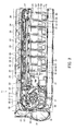
Fig. 2 is a plan view showing an internal structure of a coin handling machine to which the same coin feeding device is applied. -
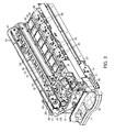
Fig. 3 is a perspective view showing the internal structure of the same coin handling machine. -
Fig. 4 is a perspective view of the same coin handling machine. -
Figs. 5 show a coin feeding device according to a second embodiment of the present invention, andFig. 5(a) is a sectional view in use andFig. 5(b) is a sectional view of a state where a separating roller is withdrawn. -
Figs. 6 show a coin feeding device according to a third embodiment of the present invention, andFig. 6(a) is a sectional view in use andFig. 6(b) is a sectional view of a state where a transporting belt is withdrawn. -
- 26
- Stacker as coin feeding device
- 57
- Transporting belt
- 65
- Separating roller
- 66
- Moving unit
- Hereinafter, embodiments of the present invention will be described with reference to the drawings.
- A first embodiment is shown in
Figs. 1 to Fig. 4 . -
Fig. 4 is a perspective view of acoin handling machine 11. Thiscoin handling machine 11 is electrically connected to, for example, a POS register, and can be used as an automatic change dispenser capable of automatically depositing and dispensing coins. - The
machine body 12 of thecoin handling machine 11 includes aframe body 13 having a front face opened and amain body unit 14 capable of being drawn out from the front face of theframe body 13. - A
coin inlet 15 into which coins are input is formed on the upper face of themain body unit 14. On the front face right side of themain body unit 14, acoin dispensing outlet 16 from which coins are dispensed from the inside of themachine body 12 is formed, and on the front face left side of themain body unit 14, areject port 17 to which coins unacceptable into themachine body 12 are returned is formed. - Next, as shown in
Fig. 2 andFig. 3 , themain body unit 14 includes afeeding unit 21 which receives coins (shown by the reference symbol C in the figures) input from thecoin inlet 15 and feeds the coins one by one, adeposit transport unit 22 which transports coins fed from thefeeding unit 21 rearward from the front side at the left side upper portion of themain body unit 14, arecognition unit 23 which recognizes coins to be transported by thedeposit transport unit 22, apluralityof sorting units 24 which sort coins being transported by thedeposit transport unit 22 by sorting according to results of recognition by therecognition unit 23,stackers 26 as a plurality of coin feeding devices, which are successively disposed from the front side to the rear side of themachine body 12, havingcoin storing units 25 which can store coins sorted by thesorting units 24 and feed the stored coins one by one to the right side of themain body unit 14, and a dispensingtransport unit 27 which is disposed at the right side lower portion of themachine body 12 and transports coins fed from thecoin storing units 25 to thecoin dispensing outlet 16 positioned ahead. - Then, the
feeding unit 21 includes arotary disk 30 which rotates around a rotation axis at a position inclined at a predetermined angle with respect to the horizontal direction, ahopper 31 which pools coins not aligned between the hopper and the surface of therotary disk 30, and adelivery disk 32 which delivers coins one by one from the upper portion of therotary disk 30 to thedeposit transport unit 22. - The rotarydisk 30 is inclined so that the left side becomes higher and the right side becomes lower as viewed from the front face of the
machine body 12, and is rotated by driving of a motor in a feed rotating direction (counterclockwise inFig. 2 andFig. 3 ) to feed coins to thedeposit transport unit 22. On the surface of therotary disk 30, a plurality of picking-upmembers 33 projecting from the surface of therotary disk 30 are disposed at a predetermined pitch along the circumferential direction. When therotary disk 30 rotates in the feed rotating direction, the picking-upmembers 33 hold and pick up the coins one by one to the upper region of therotary disk 30. - The
delivery disk 32 is arranged to deliver the coins picked up to the upper region on therotary disk 30 by the picking-upmembers 33 to thedeposit transport unit 22 one by one. - Next, the
deposit transport unit 22 includes adeposit transport path 36 formed from the front side to the rear side at the left side upper portion of themain body unit 14. Thisdeposit transport path 36 is flush with the surface of therotary disk 30 and is inclined so that the left side is higher and the right side is lower as viewed from the front face of themachine body 12 similar to the inclination of therotary disk 30. - Along the
deposit transport path 36, adeposit transporting belt 38 is disposed bypulleys 37 disposed at the start endportion and the terminal endportion of thedeposit transport path 36. Thedeposit transporting belt 38 rotates in the transporting direction to transport coins from the start end to the terminal end of thedeposit transport path 36 by driving thepulleys 37 by motors. On the surface of thedeposit transporting belt 38 opposed to the path surface of thedeposit transport path 36, projections not shown which push and transport coins one by one are provided so as to project at a predetermined pitch along the belt longitudinal direction. - The rotation of the
deposit transporting belt 38 and coin feeding by therotary disk 30 and thedelivery disk 32 of thefeeding unit 21 are interlocked with each other, and coins fed from thefeeding unit 21 are received one by one between projections adjacent to each other of thedeposit transporting belt 38. - In the
deposit transport path 36, therecognition unit 23 and the plurality of sortingunits 24 are disposed in order along the transporting direction from the front side to the rear side. - Next, the
recognition unit 23 detects materials and diameters, etc., of coins to be transported in thedeposit transport path 36, and recognizes whether the coins are acceptable into themachine body 12 and denominations, etc., of acceptable coins. - Next, among the plurality of sorting
units 24, a sortingunit 24 positioned at a sorting position on the most upstream side in the transporting direction of thedeposit transport path 36 is a rejectedcoin sorting unit 24 which sorts coins unacceptable into themachine body 12, and the sortingunits 24 at apluralityof sortingpositions on the more transportation downstream side are denomination-specific sorting units 24 which sort coins acceptable into themachine body 12, and all sorting units are formed to have the same structure. - In each sorting
unit 24, a sortinghole 41 enabling coins to be sorted is formed on the path surface of thedeposit transport path 36, and agate 42 which opens and closes the sortinghole 41 is disposed. Thisgate 42 allows coins being transported in thedeposit transport path 36 to pass through when thegate 42 is at a coin passing position at which thegate 42 closes the sortinghole 41, and sorts coins being transported in thedeposit transport path 36 into the sortinghole 41 when thegate 42 is at a coin sorting position at which thegate 42 opens the sortinghole 41. Thegate 42 is forcibly switched between the coin passing position and the coin sorting position by an electric driving unit such as a solenoid or a motor not shown. - Coins sorted by the rejected
coin sorting unit 24 are guided to areject port 17 by a chute not shown. Coins sorted by the denomination-specific sorting units 24 are stored in thecoin storing units 25 disposed corresponding to the sortingunits 24 below the sortingunits 24. - Next, as shown in
Figs. 1 , thestackers 26 are arranged in the front-rear direction inside astacker storing unit 46 formed in the region below thedeposit transport unit 22 of themain body unit 14. - On each
stacker 26, on the upper portion, a storingframe 50 forming twocoin storing units 25 is formed, and on the lower portion, feedingmechanisms 51 which feed coins (shown by the reference symbol C inFigs. 1 ) one by one from thecoin storing units 25 are disposed. - In the storing
frame 50 of thestacker 26, a partitioningmember 52 which partitions the interior of the storingframe 50 into two is formed, and by this partitioningmember 52, twocoin storing units 25 which store coins not aligned are formed. On the upper surfaces of thecoin storing units 25, receivingports 53 which receive coins sorted by the sortingunits 24 of thedeposit transport units 22 positioned above are formed. - The
feeding mechanism 51 of thestacker 26 includes a transportingbelt 57 disposed on the bottom portion of thecoin storing unit 25 of the storingframe 50. This transportingbelt 57 is suspended byrollers deposit transport unit 22 on the left side toward the dispensingtransport unit 27 on the right side. Further, the upper surface portion of the transportingbelt 57 in contact with coins is supported by a guide not shown disposed under the upper surface. Thereference numeral 60 denotes a guide roller which guides the lower side portion of the transportingbelt 57. Coins in thecoin storing unit 25 are supported on the upper surface of the transportingbelt 57, the transportingbelt 57 rotates together with theroller 59 driven to rotate by a motor not shown, and transports coins in thecoin storing unit 25 to the dispensingtransport unit 27. - At the end portion in the direction of coin transportation by the transporting
belt 57, acoin feeding port 62 from which coins in thecoin storing unit 25 are fed one by one to the dispensingtransport unit 27 by the transportingbelt 57 is formed. - Above the transporting
belt 57 near thecoin feeding port 62, a separating roller (reverse roller) 65 is disposed so as to be opposed to the transportingbelt 57 via aclearance 64 which allows coins to pass through in a single-layered state. A driving force of a motor not shown is transmitted to this separatingroller 65 and the separating roller rotates in a direction opposite to the direction of coin transportation by the transportingbelt 57 to restrict coins fed by the transportingbelt 57 one by one. - The separating
roller 65 is supported by a movingunit 66 which rotatably moves the separatingroller 65 between a home position as a restricting position at which the separatingroller 65 keeps a predetermined clearance as theclearance 64 between the separatingroller 65 and the transportingbelt 57 and restricts coins fed by the transportingbelt 57 one by one, and a withdrawn position at which the separatingroller 65 expands theclearance 64 between the separatingroller 65 and the transportingbelt 57. This movingunit 66 includes a movingmember 68 supported on the storingframe 50 of thestacker 26 so as to swing in the up-down direction around anaxis 67, and the separatingroller 65 is supported rotatably on this movingmember 68. The movingmember 68 is locked at the restricting position by a lock mechanism not shown, and is allowed to rotatably move to the withdrawn position on the upper side by releasing the lock by this lock mechanism. - Above the transporting
belt 57 and closer to thecoin feeding port 62 than the separatingroller 65, astopper mechanism 70 which restricts feeding of coins from thecoin feeding port 62 is disposed. Thisstopper mechanism 70 includes astopper 71 and asolenoid 72 which advances and retreats thestopper 71 to and from thecoin feeding port 62 from above, and thestopper 71 enters thecoin feeding port 62 to restrict feeding of coins, and thestopper 71 withdraws from the inside of thecoin feeding port 62 to allow coins to be fed. Thesolenoid 72 is attached to the movingmember 68 and moves integrally with the separatingroller 65. - At the
coin feeding port 62, for counting the number of fed coins, asensor 74 as a coin detection unit which detects coins fed by passing through thecoin feeding port 62 is provided. Thissensor 74 projects and receives detection light through the lateral portion of the transportingbelt 57 between anupper sensor unit 75 disposed above the transportingbelt 57 and alower sensor unit 76 disposed below the transportingbelt 57 and detects feeding of coins based on detection light shaded by passage of the fed coins. Theupper sensor unit 75 is attached to the movingmember 68 and moves integrally with the separatingroller 65. - Next, as shown in
Fig. 2 andFig. 3 , the dispensingtransport unit 27 includes a dispensing transporting belt not shown disposed along the front-rear direction of themain body unit 14, and places coins ejected from thecoin feeding ports 62 of the plurality ofcoin storing units 25 on the dispensing transporting belt and transports the coins to thecoin dispensing outlet 16 ahead. - Next, operations of the
coin handling machine 11 of the present embodiment will be described. - First, a depositing operation will be described.
- Coins input into the
coin inlet 15 are received in thefeeding unit 21. In thefeeding unit 21, in response to start of a depositing operation, therotary disk 30 and thedelivery disk 32 rotate, and coins are picked up one by one by picking-upmembers 33 projecting from the surface of therotary disk 30, and fed one by one to thedeposit transport path 36 of thedeposit transport unit 22 by thedelivery disk 32. - In the
deposit transport unit 22 , thedeposit transporting belt 38 rotates, and coins fed one by one from thefeeding unit 21 into thedeposit transport path 36 are transported while being pushed by the projections of thedeposit transporting belt 38. - Coins to be transported in the
deposit transport path 36 are recognized by therecognition unit 23. - As a result of recognition by the
recognition unit 23, when a coin is unacceptable into themachine body 12, that is, a rejected coin, the rejected coin is sorted from thedeposit transport path 36 by the rejectedcoin sorting unit 24 positioned on the most upstream side in the transporting direction of thedeposit transport path 36 and returned to thereject port 17. - As a result of recognition by the
recognition unit 23, when a coin is a normal coin acceptable into themachine body 12, the coin is transported to the position of the sortingunit 24 of the corresponding sort set in advance and sorted from thedeposit transport path 36 to thecoin storing unit 25 of thestacker 26. - The coins sorted by the denomination-
specific sorting units 24 drop from the receivingports 53 of thecoin storing units 25 of the corresponding sorts into thecoin storing units 25, and stored on the transportingbelts 57 or on coins which have already been stored. - When no coin is recognized by the
recognition unit 23 for a predetermined time, it is judged that handling of coins input into thecoin inlet 15 has been completed, and driving of thefeeding unit 21 and thedeposit transport unit 22 is stopped and the depositing operation is ended. - Next, a dispensing operation will be described.
- For example, in response to a signal of a dispensing command from the POS register, in the
coin storing unit 25 of thestacker 26 storing coins of the corresponding sort to be dispensed, by rotating the transportingbelt 57 and rotating the separatingroller 65 reversely, the coins not aligned on the transportingbelt 57 are fed one by one from thecoin feeding port 62. Based on detection by thesensor 74, when the number of fed coins of the corresponding sort reaches the number of coins to be dispensed, feeding of coins is forcibly stopped by thestopper mechanism 70. - The coins fed from the
coin feeding port 62 of thecoin storing unit 25 are dispensed to thecoin dispensing outlet 16 by the dispensingtransport unit 27. - As shown in
Fig. 1(a) , when feeding coins from thecoin storing unit 25 of thestacker 26, the coins may jam between the transportingbelt 57 and the separatingroller 65. As causes of this coin jam, in the case where a plurality of coins overlapping each other enter between the transportingbelt 57 and the separatingroller 65 and are stuck, the coins are larger in diameter or thickness than the coins to be handled, or the coins are deformed coins, the coins cannot pass through the clearance between the transportingbelt 57 and the separatingroller 65 and are stuck. - To eliminate the coin jam, the lock of the moving
member 68 by the lock mechanism at the restricting position is released and the movingmember 68 is rotatably moved to the withdrawn position around theaxis 67 as shown inFig. 1(b) . - When rotatably moving the moving
member 68 to the withdrawn position, theclearance 64 between the separatingroller 65 and the transportingbelt 57 gradually expands while the separatingroller 65 moves toward thecoin feeding port 62 opposite to thecoin storing unit 25 on which the coin jam has occurred, so that even if coins are tightly stuck between the transportingbelt 57 and the separatingroller 65, the separatingroller 65 can be rotatably moved to the withdrawn position together with the movingmember 68, and the stuck state of the coins can be eliminated. - Further, by rotatably moving the moving
member 68 to the withdrawn position, thesolenoid 72 and theupper sensor unit 75 disposed above of thecoin feeding port 62 are integrally withdrawn together with the separatingroller 65 and the region above thecoin feeding port 62 can be widely opened, so that the coins causing the coin j am can be exposed to thecoin feeding port 62. - Therefore, the coin jam can be eliminated by removing the coins causing the coin jam through the
coin feeding port 62. - After the coin jam is eliminated, as shown in
Fig. 1(a) , the movingmember 68 is rotatably moved and returned to the restricting position and locked by the lock mechanism. - Thus, even if coins jam between the transporting
belt 57 and the separatingroller 65, the coin jam can be easily eliminated by moving the separatingroller 65 by the movingunit 66 without using an exclusive removing jig. - When the coins causing a coin jam are coins with the potential for causing a coin jam, which cannot pass through the clearance between the transporting belt and the separating roller, such as large-diameter coins, thick coins, and deformed coins, if the coins causing a coin jam are only returned into the
coin storing unit 25 by an exclusive removing jig as in the conventional case, coin jam is caused again, and in order to prevent this, coins with the potential for causing a coin jam must be found among many coins stored in thecoin storing unit 25 and taken out, and this is troublesome. On the other hand, by moving the separatingroller 65 by the movingunit 66, the coins with the potential for causing a coin jam can be easily identified and removed through thecoin feeding port 62. - The moving
unit 66 is not limited to rotatably moving the separatingroller 65 around theaxis 67 in a direction to expand theclearance 64 between the separatingroller 65 and the transportingbelt 57, but may slide the separatingroller 65 in a direction to expand theclearance 64 between the separatingroller 65 and the transportingbelt 57 as in the second embodiment shown inFig. 5 . - This moving
unit 66 includes agroove portion 81 provided along the up-down direction on the storingframe 50 of thestacker 26 and a movingmember 83 supported slidably in the up-down direction via aslide axis 82 engaging movably along thegroove portion 81, and the separatingroller 65, thesolenoid 72 and theupper sensor unit 75 are attached integrally to the movingmember 83. This movingmember 83 is also locked by a lock mechanism not shown at a restricting position, and is allowed to slide to the withdrawn position on the upper side by releasing the lock by the lock mechanism. - Then, as shown in
Fig. 5(a) , when feeding coins from thecoin storing unit 25 of thestacker 26, in order to eliminate coin jam occurring between the transportingbelt 57 and the separatingroller 65, the lock of the movingmember 83 by the lock mechanism at the restricting position is released, and as shown inFig. 5(b) , the movingmember 68 is slid to the withdrawn position on the upper side along thegroove portion 81 with which theslide axis 82 engages. - When sliding the moving
member 83 to the withdrawn position, the separatingroller 65 moves in a direction to expand theclearance 64 between the separatingroller 65 and the transportingbelt 57, so that even if coins are tightly stuck between the transportingbelt 57 and the separatingroller 65, the separatingroller 65 can be slid to the withdrawn position on the upper side together with the movingmember 68, so that the stuck state of the coins can be eliminated. - Moreover, by sliding the moving
member 68 to the withdrawn position, thesolenoid 72 and theupper sensor unit 75 disposed above thecoin feeding port 62 can be withdrawn integrally together with the separatingroller 65 and the region above thecoin feeding port 62 can be widely opened, so that the coins causing a coin jam can be exposed to thecoin feeding port 62. - Therefore, by removing coins causing a coin jam through the
coin feeding port 62, the coin jam can be eliminated. - After the coin jam is eliminated, as shown in
Fig. 5(a) , the movingmember 68 is slid and returned to the restricting position on the lower side, and locked by the lock mechanism. - Therefore, in this case, as in the case where the separating
roller 65 is rotatably moved, coin jam can also be easily eliminated. - The moving
unit 66 is not limited to moving the separatingroller 65 in a direction to expand theclearance 64 between the separatingroller 65 and the transportingbelt 57, but may move the transportingbelt 57 in a direction to expand theclearance 64 between the transportingbelt 57 and the separatingroller 65 as in the third embodiment shown inFigs. 6 . - With this moving
unit 66, theroller 59 positioned on the end portion in the transporting direction of the transportingbelt 57 below thecoin feeding port 62 is supported on a moving member not shown which rotatably moves around a predetermined axis or supported on a supporting member not shown which slides. Accordingly, the end portion in the transporting direction of the transportingbelt 57 positioned below thecoin feeding port 62 can be moved between a home position as a restricting position at which coins fed by the transportingbelt 57 are restricted one by one by keeping theclearance 64 between the transportingbelt 57 and the separatingroller 65 as predetermined, and a withdrawn position on the lower side at which theclearance 64 between the transportingbelt 57 and the separatingroller 65 is expanded. This moving member is also locked by a lock mechanism not shown at the restricting position, and is allowed to move to the withdrawn position by releasing the lock by the lock mechanism. - As shown in
Fig. 6(a) , when feeding coins from thecoin storing unit 25 of thestacker 26, in order to eliminate coin jam occurring between the transportingbelt 57 and the separatingroller 65, the lock of the moving member by the lock mechanism at the restricting position is released, and as shown inFig. 6(b) , the moving member is moved to the withdrawn position on the lower side by rotation or sliding. - When moving the moving member to the withdrawn position, the transporting
belt 57 moves in a direction to expand theclearance 64 between the transportingbelt 57 and the separatingroller 65, so that even if coins are tightly stuck between the transportingbelt 57 and the separatingroller 65, the transportingbelt 57 can be moved to the withdrawn position on the lower side together with the moving member, so that the stuck state of the coins can be eliminated. - Further, by moving the transporting
belt 57 to the withdrawn position, the region below thecoin feeding port 62 can be widely opened, so that the coins causing a coin jam can be exposed to thecoin feeding port 62. - Therefore, by removing coins causing a coin jam from the
coin feeding port 62, the coin jam can be eliminated. - After the coin jam is eliminated, as shown in
Fig. 6(a) , the moving member is moved and returned to the restricting position on the upper side, and locked by the lock mechanism. - Therefore, in this case, coin jam can also be easily eliminated as in the case where the separating
roller 65 is moved. - As an embodiment for expanding the
clearance 64 between the separatingroller 65 and the transportingbelt 57 by moving the separatingroller 65 by the movingunit 66, in addition to the method in which the separatingroller 65 is rotatably moved upward, the separatingroller 65 may be rotated in another direction such as the lateral direction, and in addition to the method in which the separatingroller 65 is slid upward, the separatingroller 65 may be slid in the axial direction or slid to the coin feeding side, and moreover, the separatingroller 65 may be arranged to be removed to the upper side or the coin feeding side with respect to thestacker 26. - Alternatively, both of the separating
roller 65 and the transportingbelt 57 may be arranged to move in a direction to expand theclearance 64. - A coin feeding device of the present invention is used for, in addition to coin storing units which store coins by sorting and feeding them, all other feeding structures which feed coins one by one by using a transporting belt and a separating roller, such as a feeding unit which receives input coins and feeds them.
Claims (5)
- A coin feeding device comprising:a transporting belt which transports coins;a separating roller which is opposed to the transporting belt via a clearance in which coins pass through in a single-layered state and restricts the coins fed by the transporting belt to be in a single-layered state; anda moving unit which moves at least one of the transporting belt and the separating roller in a direction to expand the clearance between the transporting belt and the separating roller.
- The coin feeding device according to Claim 1, wherein
the moving unit rotatably moves the separating roller around a predetermined pivot in a direction to expand the clearance between the separating roller and the transporting belt. - The coin feeding device according to Claim 1, wherein
the moving unit slides the separating roller in a direction to expand the clearance between the separating roller and the transporting belt. - The coin feeding device according to Claim 1, wherein
the moving unit rotatably moves at least a part of the transporting belt around a predetermined pivot in a direction to expand the clearance between the transporting belt and the separating roller. - The coin feeding device according to Claim 1, wherein
the moving unit slides at least a part of the transporting belt in a direction to expand the clearance between the transporting belt and the separating roller.
Applications Claiming Priority (1)
| Application Number | Priority Date | Filing Date | Title |
|---|---|---|---|
| PCT/JP2008/051298 WO2009095995A1 (en) | 2008-01-29 | 2008-01-29 | Coin delivery machine |
Publications (2)
| Publication Number | Publication Date |
|---|---|
| EP2246827A1 true EP2246827A1 (en) | 2010-11-03 |
| EP2246827A4 EP2246827A4 (en) | 2012-11-14 |
Family
ID=40912364
Family Applications (1)
| Application Number | Title | Priority Date | Filing Date |
|---|---|---|---|
| EP08704080A Withdrawn EP2246827A4 (en) | 2008-01-29 | 2008-01-29 | Coin delivery machine |
Country Status (4)
| Country | Link |
|---|---|
| US (1) | US8961276B2 (en) |
| EP (1) | EP2246827A4 (en) |
| JP (1) | JPWO2009095995A1 (en) |
| WO (1) | WO2009095995A1 (en) |
Cited By (2)
| Publication number | Priority date | Publication date | Assignee | Title |
|---|---|---|---|---|
| EP2672468A1 (en) * | 2012-06-04 | 2013-12-11 | Wincor Nixdorf International GmbH | Device for separating coins with a reverse roller and a brush pair assembly for separating coins lying beside each other |
| CN106251481A (en) * | 2015-11-28 | 2016-12-21 | 华南理工大学 | A kind of coin segregation apparatus |
Families Citing this family (7)
| Publication number | Priority date | Publication date | Assignee | Title |
|---|---|---|---|---|
| US8522950B2 (en) * | 2011-09-09 | 2013-09-03 | Outerwall Inc. | Debris diverter for coin counting machine and associated method of manufacture and operation |
| US9036890B2 (en) | 2012-06-05 | 2015-05-19 | Outerwall Inc. | Optical coin discrimination systems and methods for use with consumer-operated kiosks and the like |
| US8550227B1 (en) * | 2012-09-12 | 2013-10-08 | Outerwall Inc. | Auto-positioning sensors for coin counting devices |
| US8967361B2 (en) | 2013-02-27 | 2015-03-03 | Outerwall Inc. | Coin counting and sorting machines |
| US9022841B2 (en) | 2013-05-08 | 2015-05-05 | Outerwall Inc. | Coin counting and/or sorting machines and associated systems and methods |
| US9443367B2 (en) | 2014-01-17 | 2016-09-13 | Outerwall Inc. | Digital image coin discrimination for use with consumer-operated kiosks and the like |
| JP7402071B2 (en) * | 2020-02-13 | 2023-12-20 | 東芝テック株式会社 | Coin transport device and coin change machine |
Family Cites Families (14)
| Publication number | Priority date | Publication date | Assignee | Title |
|---|---|---|---|---|
| US3760099A (en) | 1971-11-01 | 1973-09-18 | Tektronix Inc | Video amplifier for a color television apparatus |
| JPS5539496Y2 (en) * | 1975-10-30 | 1980-09-16 | ||
| JPS5323481A (en) * | 1976-08-17 | 1978-03-03 | Taiwa Sangiyou Kk | Method and device for conveying and loading shape material etc* |
| JPS63183744A (en) | 1987-01-26 | 1988-07-29 | Nabeya:Kk | Production of porous casting |
| JPS63183744U (en) * | 1987-02-09 | 1988-11-25 | ||
| US4920730A (en) * | 1987-08-31 | 1990-05-01 | Nihon Kinsen Kikai Kabushiki Kaisha | Coin wrapping apparatus |
| JPH0761639A (en) * | 1993-08-30 | 1995-03-07 | Murata Mach Ltd | Paper sheet feeder |
| KR100445563B1 (en) * | 1996-05-30 | 2005-05-16 | 아사히 세이코 가부시키가이샤 | Coin classification apparatus |
| US6264021B1 (en) * | 1996-10-21 | 2001-07-24 | Bell & Howell Mail & Messaging Technologies Company | High speed envelope packing apparatus |
| JP3481816B2 (en) * | 1997-03-25 | 2003-12-22 | 東芝テック株式会社 | Coin separation and delivery device |
| JP2002245506A (en) | 2001-02-20 | 2002-08-30 | Glory Ltd | Hard money delivery device |
| JP4604155B2 (en) * | 2003-04-24 | 2010-12-22 | 旭精工株式会社 | Coin separator |
| JP4421879B2 (en) * | 2003-11-20 | 2010-02-24 | 株式会社湯山製作所 | Medicine pack carrier |
| JP4758190B2 (en) * | 2005-09-29 | 2011-08-24 | グローリー株式会社 | Coin feeding and conveying device |
-
2008
- 2008-01-29 JP JP2009551346A patent/JPWO2009095995A1/en active Pending
- 2008-01-29 US US12/735,556 patent/US8961276B2/en not_active Expired - Fee Related
- 2008-01-29 WO PCT/JP2008/051298 patent/WO2009095995A1/en not_active Ceased
- 2008-01-29 EP EP08704080A patent/EP2246827A4/en not_active Withdrawn
Cited By (2)
| Publication number | Priority date | Publication date | Assignee | Title |
|---|---|---|---|---|
| EP2672468A1 (en) * | 2012-06-04 | 2013-12-11 | Wincor Nixdorf International GmbH | Device for separating coins with a reverse roller and a brush pair assembly for separating coins lying beside each other |
| CN106251481A (en) * | 2015-11-28 | 2016-12-21 | 华南理工大学 | A kind of coin segregation apparatus |
Also Published As
| Publication number | Publication date |
|---|---|
| JPWO2009095995A1 (en) | 2011-05-26 |
| WO2009095995A1 (en) | 2009-08-06 |
| US8961276B2 (en) | 2015-02-24 |
| EP2246827A4 (en) | 2012-11-14 |
| US20100330892A1 (en) | 2010-12-30 |
Similar Documents
| Publication | Publication Date | Title |
|---|---|---|
| US8961276B2 (en) | Coin feeding device | |
| EP2270755B1 (en) | Coin processing device | |
| EP2249316B1 (en) | Coin transporting device | |
| EP2131333B1 (en) | Coin dispensing device and coin processing machine | |
| WO2008072544A1 (en) | Coin receiving and discharging device | |
| EP2026294B1 (en) | Coin receiving/dispensing machine | |
| US8498736B2 (en) | Coin handling machine | |
| CN101379531B (en) | coin dispenser | |
| JP4988748B2 (en) | Coin storage and dispensing device | |
| JP3058150B2 (en) | Paper handling equipment | |
| WO2008072545A1 (en) | Coin handling device | |
| JP5988804B2 (en) | Coin processing equipment | |
| JP3247185B2 (en) | Coin processing equipment | |
| EP3716231B1 (en) | Coin handling apparatus | |
| JP2972513B2 (en) | Coin depositing and dispensing machine | |
| JP4936993B2 (en) | Bar metal storage device | |
| EP2383704A1 (en) | Coin dispenser | |
| JP5073217B2 (en) | Coin deposit and withdrawal machine | |
| JP2007279909A (en) | Coin feeding device | |
| JP2008293246A (en) | Money bar storage device | |
| JP2000251105A (en) | Coin distributing device and coin clasifying machine | |
| HK1113846A1 (en) | Bill processor | |
| HK1113846B (en) | Bill processor |
Legal Events
| Date | Code | Title | Description |
|---|---|---|---|
| PUAI | Public reference made under article 153(3) epc to a published international application that has entered the european phase |
Free format text: ORIGINAL CODE: 0009012 |
|
| 17P | Request for examination filed |
Effective date: 20100729 |
|
| AK | Designated contracting states |
Kind code of ref document: A1 Designated state(s): AT BE BG CH CY CZ DE DK EE ES FI FR GB GR HR HU IE IS IT LI LT LU LV MC MT NL NO PL PT RO SE SI SK TR |
|
| AX | Request for extension of the european patent |
Extension state: AL BA MK RS |
|
| DAX | Request for extension of the european patent (deleted) | ||
| A4 | Supplementary search report drawn up and despatched |
Effective date: 20121015 |
|
| RIC1 | Information provided on ipc code assigned before grant |
Ipc: G07D 3/02 20060101ALI20121009BHEP Ipc: G07D 3/14 20060101ALI20121009BHEP Ipc: G07F 19/00 20060101ALI20121009BHEP Ipc: G07D 13/00 20060101AFI20121009BHEP Ipc: G07D 3/16 20060101ALI20121009BHEP Ipc: G07D 1/02 20060101ALI20121009BHEP |
|
| 17Q | First examination report despatched |
Effective date: 20151222 |
|
| STAA | Information on the status of an ep patent application or granted ep patent |
Free format text: STATUS: THE APPLICATION IS DEEMED TO BE WITHDRAWN |
|
| 18D | Application deemed to be withdrawn |
Effective date: 20180801 |