EP2246728A1 - Head mounted display - Google Patents
Head mounted display Download PDFInfo
- Publication number
- EP2246728A1 EP2246728A1 EP09275031A EP09275031A EP2246728A1 EP 2246728 A1 EP2246728 A1 EP 2246728A1 EP 09275031 A EP09275031 A EP 09275031A EP 09275031 A EP09275031 A EP 09275031A EP 2246728 A1 EP2246728 A1 EP 2246728A1
- Authority
- EP
- European Patent Office
- Prior art keywords
- image
- user
- eye
- optical
- bearing light
- Prior art date
- Legal status (The legal status is an assumption and is not a legal conclusion. Google has not performed a legal analysis and makes no representation as to the accuracy of the status listed.)
- Ceased
Links
- 230000003287 optical effect Effects 0.000 claims abstract description 53
- 210000003128 head Anatomy 0.000 description 9
- 210000001747 pupil Anatomy 0.000 description 6
- 238000004364 calculation method Methods 0.000 description 2
- 238000004088 simulation Methods 0.000 description 2
- 238000010276 construction Methods 0.000 description 1
- 239000011159 matrix material Substances 0.000 description 1
- 230000004297 night vision Effects 0.000 description 1
- 230000000644 propagated effect Effects 0.000 description 1
- 230000001902 propagating effect Effects 0.000 description 1
- 230000001681 protective effect Effects 0.000 description 1
- 229910000679 solder Inorganic materials 0.000 description 1
- 230000001502 supplementing effect Effects 0.000 description 1
- 230000000007 visual effect Effects 0.000 description 1
Images



Classifications
-
- G—PHYSICS
- G02—OPTICS
- G02B—OPTICAL ELEMENTS, SYSTEMS OR APPARATUS
- G02B27/00—Optical systems or apparatus not provided for by any of the groups G02B1/00 - G02B26/00, G02B30/00
- G02B27/01—Head-up displays
- G02B27/017—Head mounted
- G02B27/0172—Head mounted characterised by optical features
-
- G—PHYSICS
- G02—OPTICS
- G02B—OPTICAL ELEMENTS, SYSTEMS OR APPARATUS
- G02B27/00—Optical systems or apparatus not provided for by any of the groups G02B1/00 - G02B26/00, G02B30/00
- G02B27/42—Diffraction optics, i.e. systems including a diffractive element being designed for providing a diffractive effect
- G02B27/4205—Diffraction optics, i.e. systems including a diffractive element being designed for providing a diffractive effect having a diffractive optical element [DOE] contributing to image formation, e.g. whereby modulation transfer function MTF or optical aberrations are relevant
-
- G—PHYSICS
- G02—OPTICS
- G02B—OPTICAL ELEMENTS, SYSTEMS OR APPARATUS
- G02B27/00—Optical systems or apparatus not provided for by any of the groups G02B1/00 - G02B26/00, G02B30/00
- G02B27/01—Head-up displays
- G02B27/0101—Head-up displays characterised by optical features
- G02B2027/0123—Head-up displays characterised by optical features comprising devices increasing the field of view
-
- G—PHYSICS
- G02—OPTICS
- G02B—OPTICAL ELEMENTS, SYSTEMS OR APPARATUS
- G02B27/00—Optical systems or apparatus not provided for by any of the groups G02B1/00 - G02B26/00, G02B30/00
- G02B27/0081—Optical systems or apparatus not provided for by any of the groups G02B1/00 - G02B26/00, G02B30/00 with means for altering, e.g. enlarging, the entrance or exit pupil
Definitions
- Prior art head-mounted display apparatus employs a flat waveguide between the user's eye and a visor of a helmet, which waveguide acts as a combiner and expands a pupil of image-bearing light to present an image to the user.
- These displays must be made small and compact because they must fit into the restricted space between the user's eye and the helmet, and this can lead to cost and complexity.
- images are projected onto the inner surface of a visor and reflected from it so as to be visible to the wearer.
- the diffraction means may comprise an input diffractive element and an output diffractive element.
- the apparatus may comprise a respective image-bearing light source for each diffraction means, the light source being dispersed such that relative angular movement of the light sources about an axis of symmetry of the optical element adjusts the inter-pupillary spacing of the images presented to the user's eyes.
- Figures 5A to 5D show various forms of image-generating light sources which may be used in the invention.
- light from a point source 50 passes through a beam splitter 52 to illuminate the surface of a reflective display panel 54.
- Light reflected from the panel, now image-bearing, is reflected at the beam splitter through a focussing lens 60 to the input diffracting element 34 at thence to the user's eye 18 as already described.
- the structure once again contains curved fringes (grating lines) that allow for a bulk diffraction along the prime axis of the waveguide 20 but with a spherical component to give focussing power.
- This spherical focussing component again curves the fringes to give an azimuth component of diffraction and also contains a variable pitch of fringe in the vertical axis to give a focussing component in the elevation axis.
- a typical known flat waveguide display 62 ( figure 6A ) has the capability of allowing a wide field of view in the axis parallel to the diffractive element structure 64.
- this waveguide is not pupil-forming and consequently the edge 66 of the field of view does not fall usefully within the exit pupil 68 of the display.
- an extremely large waveguide would be required to avoid vignetting at the edge of the field of view, leading to difficulties in accommodating it within head or helmet-mounted apparatus.
- the optical system of the present invention is pupil-forming, and so a compact display with a wide field of view can be provided as shown in figure 6B .
Landscapes
- Physics & Mathematics (AREA)
- General Physics & Mathematics (AREA)
- Optics & Photonics (AREA)
Abstract
A helmet or head-mounted apparatus has a visor or other curved optical element in front of at least one eye of a wearer, which element also is used as a waveguide. Image-bearing light is injected into the waveguide via an input diffractive element, and propagates through the visor to an output diffractive element which releases the light. The optical powers of the curved waveguide and the input and output diffractive elements are selected so that the released light is delivered as an image to the user's eye.
Description
- This invention relates to a head-mounted display apparatus, in which a display is provided on a surface through which a wearer of the apparatus views the outside world. Included in the term "head-mounted display apparatus" are visors, goggles and spectacles worn directly on the head, and also such articles carried indirectly on the head by being mounted on a helmet, or other head gear. It also includes visors, goggles and viewing windows which are built into helmets or other head gear.
- The invention is applicable to equipment worn by military personnel, in particular infantrymen and crews of armoured fighting vehicles, aircrew and other airborne personnel (whether civil or military) who wear helmets, divers, and other personnel to whom visual information must be transmitted under difficult conditions. Examples are fire-fighters and other emergency services personnel, and the police.
- The invention may also be applicable to head-mounted virtual reality display apparatus, in which a display is provided to a wearer of the apparatus via a surface which obscures his view of the outside world.
- Prior art head-mounted display apparatus employs a flat waveguide between the user's eye and a visor of a helmet, which waveguide acts as a combiner and expands a pupil of image-bearing light to present an image to the user. These displays must be made small and compact because they must fit into the restricted space between the user's eye and the helmet, and this can lead to cost and complexity.
- In other known apparatus, images are projected onto the inner surface of a visor and reflected from it so as to be visible to the wearer.
- Precise positioning of the apparatus on the head is necessary for these devices to work. This is not always achievable especially when the helmet may have to be donned quickly under field conditions, e.g. when used by ground troops.
- The present invention seeks to provide alternatives to these prior art solutions, which may avoid some of the disadvantages thereof.
- According to the invention a head-mounted or helmet-mounted display apparatus comprising a curved optical element which in use is disposed in front of an eye of a user and which is configured to operate as a waveguide, a source of image-bearing light, and diffraction means for propagation of image-bearing light through the optical element and for releasing the image-bearing light from the optical element, optical element and the diffraction means having optical powers such that the released light provides a viable image to the user's eye.
- As noted above, in many embodiments of the invention, the curved optical element may be a transparent element through which the user views the outside world.
- The image-bearing light may be introduced into the optical element for propagation therethrough via an input reflective, diffractive or transmissive element.
- The diffraction means may comprise an input diffractive element and an output diffractive element.
- At least the output diffractive element may have spherical optical power in azimuth and elevation relative to the user's eye.
- The spherical optical power may be provided by non-parallel diffractive features of the output diffractive element.
- The diffractive features may comprise a curved grating or other curved diffractive component.
- The output diffractive element may have an angular bandwidth which is less than the angular field of view of the visible image provided to the user's eye, the angle of diffraction of the output diffractive element varying across the element so as to present the image to the user's eye.
- Preferably an optical axis of a waveguide formed within the optical element lies in a plane containing a sagittal axis of symmetry of the optical element and an eye of the user.
- The source of image-bearing light may comprise a display panel and means for illuminating it, or a self-illuminating display panel.
- Preferably the optical powers of optical element and the diffraction means are such that image bearing light passes from the image-bearing light source to the input diffractive element of the diffraction means without being acted upon by an element having optical power.
- The apparatus may comprise further said diffraction means configured with the optical element to provide a visible image to the user's other eye.
- The apparatus may comprise a respective image-bearing light source for each diffraction means, the light source being dispersed such that relative angular movement of the light sources about an axis of symmetry of the optical element adjusts the inter-pupillary spacing of the images presented to the user's eyes.
- There may be a common light source for each diffraction means, and means for switching the image-bearing light repeatedly between the first and further diffraction means whereby to provide a visible image to each of the user's eyes. The switching means may be an input element which is common to the first and further diffraction means, and switchable between them.
- The image-bearing light source may be configured to modify the image synchronously with switching of the image-bearing light whereby to provide a pair of binocular images to the user's eyes.
- The invention will now be described merely by way of example with reference to the accompanying drawings, wherein
-
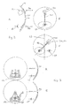
Figure 1A , B, C and D show various forms of head-mounted apparatus, of whichFigure 1A in prior art andFigures 1B, 1C and 1D are according to the invention; -
Figures 2A and 2B are diagrammatic side and front views of the embodiment ofFigure 1B , andFigure 2C in a variation of the embodiment ofFigure 2B ; -
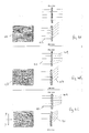
Figures 3A and 3B , and4A and 4B illustrate a principle used in the invention; -
Figures 5A to 5D illustrate various embodiments of the invention; -
Figures 6A, 6B, 7A and 7B explain features of the invention,Figures 6A and 7A being prior art, and -
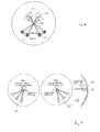
Figures 7 ,8 and 9 illustrate further embodiments of the invention. - Referring to
Figure 1A , a solder is shown wearing ahelmet 10 having acurved visor 12, through which he views the outside world. Supported from the helmet by structure not shown is alight source 14 from which projects upwards a flat slab-like waveguide 16, which is disposed under the visor in front of the user'seye 18. An image from thesource 14 is propagated through the waveguide and diffracted out to the user's eye as a visible image. Whilst effective, this arrangement can be costly, and the presence of the waveguide close to the user's eye can present a hazard. - In an embodiment of the invention shown in
figure 1B ,part 20 of the curved visor of the helmet is itself used as the waveguide. Thelight source 14 is shown here mounted outside the helmet, but it can be placed inside subject to space being available, and to it being located so as not to present a hazard to the user. - This concept can be extended to cases where a protective helmet is not necessary, or can be worn separately from the display apparatus. Thus in
figure 1C , a pair of goggles, which can be worn alone or under a visorless helmet, comprises a curved visor 22, held onto the user's head by an elasticated strap 24. A portion 26 of the visor is configured to operate as a waveguide, receiving image-bearing light from asource 14 and delivering it to the user'seye 18. Similarly infigure 1D , the curved lens portions 28 of a pair ofspectacles 30 include a waveguide portion 32 driven by alight source 14 to deliver an image to the user'seye 18. - Referring to
figures 2A and 2B , thevisor 12 offigure 1B comprises an input diffractive element or grating 34, an output diffractive element or grating 36 angularly spaced from the input element vertically around the visor. Thewaveguide portion 20 of the visor lies between the input and output diffractive elements. Thelight source 14 delivers image-bearing light to theinput element 34, from which it propagates through thewaveguide portion 20, under total internal reflection, to theoutput element 36 at thence is delivered to the user'seye 18.Figure 2C shows a preferred arrangement in which thelight source 14 is diagonally offset around the visor so that it is disposed above theother eye 38 of the user. The waveguide portion, the axis of which is shown at 40 infigure 2C passes through an axis ofsymmetry 42 of thewaveguide portion 20 of thevisor 14, lying in themid-sagittal plane 43 of the user's head. The visor, at least in this region, is of spherical shape, and is symmetrical about themid-sagittal plane 43. This allows the use of a single continuous curved visor structure rather than having to deploy a visor made of several non-continuous surfaces. - The invention requires a pupil of image-bearing light to be conveyed from the image source to the user's eye. This is achieved by supplementing the optical power inherent in the curvature of the
waveguide portion 20 of the visor 14 (it is of constant thickness between parallel curved surfaces) with optical power in at least theoutput diffracting element 36, and if appropriate in the input diffracting element as well. In this embodiment, the extra optical power is obtained by adding spherical power in the azimuthal plane of the outputdiffractive element 36 in front of the eye. Thus the spherical power is provided in both azimuth and elevation relative to the user'seye 18. Referring tofigure 3A , here it is illustrated that a conventional straight-ruledgrating 44 would not converge diffracting light to a pupil at the user's eye. If the grating instead has increased spherical power, as showing at 46 infigure 3B , convergence to a pupil at the eye is achieved. The spherical power is provided by curving thegrating lines 48 upwards gradually across their length and varying their spacing relative to the centre of the grating, thereby providing a diffractive component orthogonally to the main sideways extent of the grating lines. - In more detail,
figure 4A shows how theconventional grating 44 offigure 3A diffracts parallel rays oflight 45 incident anywhere on its surface through the same angle so that they remain parallel after diffraction. In other words the grating has zero optical power (infinite focal length). Infigure 4B , thegrating lines 48 are curved upwards, whilst maintaining the same even spacing as thegrating lines 44 offigure 3A . Incident parallel rays remain parallel after diffraction when viewed in elevation as at 47, but are convergent when viewed in the azimuthal plane. When additionally the spacing of the grating lines is reduced as a function of the distance y from the horizontal centre line of the grating (figure 4C ), parallel incident rays also are convergent after diffraction in the elevational plane. Thus the grating can be given spherical and/or cylindrical optical power. - By applying these principles to the grating lines of the output and/or input
diffractive elements portion 20 of the visor which acts as a waveguide is of part-spherical shape and of constant thickness. It thereby has spherical optical power with respect to light propagating through it from the input to the output diffractive elements. The optical powers of the waveguide and these two elements are chosen and combined using optical calculation methods or by iterative simulation so that theelements -
Figures 5A to 5D show various forms of image-generating light sources which may be used in the invention. Infigure 5A , light from apoint source 50 passes through a beam splitter 52 to illuminate the surface of areflective display panel 54. Light reflected from the panel, now image-bearing, is reflected at the beam splitter through a focussinglens 60 to theinput diffracting element 34 at thence to the user'seye 18 as already described. - In
figure 5B thedisplay panel 54 is transmissive rather than reflective. Light from thesource 50 passes through the display panel and thelens 60 to theinput diffracting element 34 as before. - In
figure 5C thedisplay panel 54 is self-illuminated. For example it may be an organic light emitting diode matrix. Light from the display passes through thelens 60 to the inputdiffractive element 34. - In a preferred form of the invention, the functionality of the focussing
lens 60 is achieved within the diffracting means 34, 36 and thewaveguide 20. For example the focussing power of the lens may be achieved in theinput diffracting element 34. The complex optical power of thelens system 60, which would otherwise be used to collimate the image on thedisplay panel 54 into the waveguide can be contained within theinput diffracting element 34. Once again this is achieved through the use of a complex diffracting fringe structure that is not just a plane linear grating. The exact power required depends on the shape and form of the curved waveguide and the optical power contained within theoutput diffracting element 36. Regardless of the exact prescription of this optical power the structure once again contains curved fringes (grating lines) that allow for a bulk diffraction along the prime axis of thewaveguide 20 but with a spherical component to give focussing power. This spherical focussing component again curves the fringes to give an azimuth component of diffraction and also contains a variable pitch of fringe in the vertical axis to give a focussing component in the elevation axis. - Then as shown in
figure 5D , thelens 60 can be omitted, simplifying the optical architecture and achieving apparatus of lower mass, volume and complexity. - A typical known flat waveguide display 62 (
figure 6A ) has the capability of allowing a wide field of view in the axis parallel to thediffractive element structure 64. However this waveguide is not pupil-forming and consequently theedge 66 of the field of view does not fall usefully within theexit pupil 68 of the display. Also, an extremely large waveguide would be required to avoid vignetting at the edge of the field of view, leading to difficulties in accommodating it within head or helmet-mounted apparatus. In contrast the optical system of the present invention is pupil-forming, and so a compact display with a wide field of view can be provided as shown infigure 6B . - The present invention also can be advantageous in that it can be implemented using only lower angular bandwidth gratings.
Figure 7A is an enlarged view of part of the prior art structure offigure 1A . Anoutput diffraction element 70 of the slab waveguide 16 is required to have a full angular bandwidth ϕ at every point on the diffraction element ifrays 72 at the margins of the field of view are to be resolved within the compass of the user's eye. This brings with it the disadvantage that extraneous light (for example, sunlight) passing through the waveguide 16 from the outside world may couple into the diffractive element and be directed to the user's eye. This can be distracting and may veil the user's view of the display and of the outside world. - In the present invention, however, as shown in
figure 7B , the outputdiffractive element 36 may be displaced from the pupil at the user's eye, so that each part of the diffractive element need have only a relatively narrow angular bandwidth θ centred around the angle at which that part of the element is required to diffract image-bearing light to the user'seye 18. For example theregion element 36 all have the same angular bandwidth, but the spherical power of theelement 36 is such that each region diffracts light received from within thewaveguide 20 at a different angle so as to deliver it to the user's eye. Thus rays diffracted atregion 74 are directed at an angle x to the normal at the surface of theelement 36, whereas rays diffracted atregion 78 are directed almost normally to the element surface. Rays atregion 76 are at an intermediate angle. By limiting the angular bandwidth of the diffractive elements in this manner, less solar energy will be coupled to the eye via the waveguide element. - The invention has so far been described in the context of presenting an image to one eye of the viewer. However it is well adapted for bi-ocular or binocular applications. Thus,
figure 2C shows an embodiment in which theimage source 14 andinput diffracting element 34 are disposed over one eye of the user, and an image is transmitted to his other eye. The arrangement can be replicated for the other eye as shown infigure 8 , where an additional image source 80 provides image bearing light to further input and output gratings arranged to diffract the light diagonally through thecentral waveguiding part 20 of the visor and thence to the user'sother eye 38. The propagation paths of the light passing to the user'seyes symmetry 42 of the visor. By making the input and output diffractive elements of each path oversized and optimised, it is possible then to allow for relative rotational movement of the light sources around theaxis 42. This permits variations in the inter-pupillary distance (eye spacing) of different wearers of the same apparatus to be accommodated, as illustrated in exaggerated form infigure 8 . This facility is particularly useful for helmet-mounted equipment which may be used by more than one person, for example by foot soldiers, or where the helmet has to be donned quickly and not always into a repeatable position on the user's head. The images delivered to the user's two eyes can be identical (i.e. a bi-ocular arrangement); this is suitable for the presentation of data. Alternatively, two slightly different images may be prevented (left eye and right eye images) so as to provide a binocular or stereoscopic image giving an impression of depth. Such images for example can be obtained in a night-vision system from a pair of helmet-mounted infra-red cameras. Alternatively, the image can be video or graphical information supplied from elsewhere. -
Figure 9 shows another embodiment which provides bi-ocular or binocular images. There is asingle image source 82, and a switchable inputdiffractive element 84 common to both left and right eye image systems. This element is positioned on the sagittal axis of the visor and has extending from it waveguides 20 through the visor to respective right and left eyeoutput diffractive gratings 36, 36'. In a bi-ocular arrangement, the image source provides continuous image-bearing light to the inputdiffractive element 84. This element switches the light between the left and right eye paths, typically at about 50-60Hz to avoid flicker. An identical image thus is provided to both eyes. For binocular images, theimage source 82 is switched in synchronisation with thediffractive element 84, and provides slightly different images to each eye. - The invention also includes any novel features or construction of features herein disclosed, regardless of whether specifically claimed. The abstract is repeated here as part of the specification.
- A helmet- or head-mounted apparatus has a visor or other curved optical element in front of at least one eye of a wearer, which element also is used as a waveguide. Image-bearing light is injected into the waveguide via an input diffractive element, and propagates through the visor to an output diffractive element which releases the light. The optical powers of the curved waveguide and the input and output diffractive elements are selected so that the released light is delivered as an image to the user's eye.
Claims (15)
- A head-mounted or helmet-mounted display apparatus comprising a curved optical element which in use is disposed in front of an eye of a user and which is configured to operate as a waveguide, a source of image-bearing light, and diffraction means for propagation of image-bearing light through the optical element and for releasing the image bearing light from the optical element, the optical element and the diffraction means having optical powers such that the released light provides a visible image to the user's eye.
- The apparatus of claim 1 wherein the diffraction means comprises an input diffractive element and an output diffractive element.
- The apparatus of claim 2 wherein at least the output diffractive element has spherical optical power in azimuth and elevation relative to the user's eye.
- The apparatus of claim 3 where in spherical optical power is provided by non-parallel diffractive features of the output diffractive element.
- The apparatus of claim 4 wherein the diffractive features comprise a curved diffractive component.
- The apparatus of any of claims 2 to 5 wherein the output diffractive element has an angular bandwidth which is less than the angular field of view of the visible image provided to the user's eye, the angle of diffraction of the output diffractive element varying across the element so as to present the image to the user's eye.
- The apparatus of any preceding claim wherein an optical axis of a waveguide formed within the optical element lies in a plane containing a sagittal axis of symmetry of the optical element and an eye of the user.
- The apparatus of any preceding claim wherein the source of the image-bearing light comprises a display panel and means for illuminating it, or a self-illuminating display panel.
- The apparatus of any preceding claim wherein the optical powers of the optical element and the diffraction means are such that image-bearing light passes from the image-bearing light source to the diffraction means without being acted upon by an element having optical power.
- The apparatus of any preceding claim comprising a further said diffraction means configured with the optical element to provide a visible image to the user's other eye.
- The apparatus of claim 10 comprising a respective image-bearing light source for each diffraction means, the light sources being disposed such that relative angular movement of the light sources about an axis of symmetry of the optical element adjusts the inter-pupillary spacing of the image presented to the user's eyes.
- The apparatus of claim 10 comprising a common light source for each diffraction means, and means for switching the image-bearing light repeatedly between the first and further diffraction means whereby to provide a visible image to each of the user's eyes.
- The apparatus of claim 12 wherein the switching means is an input element which is common to both the first and the further diffraction means, and switchable between them.
- The apparatus of claim 12 or claim 13 wherein the image-bearing light source is configured to modify the image synchronously with switching of the image-bearing light whereby to provide a pair of binocular images to the main eyes.
- The apparatus of any preceding claim wherein the curved optical element is a transparent element through which the user views the outside world.
Priority Applications (10)
| Application Number | Priority Date | Filing Date | Title |
|---|---|---|---|
| EP09275031A EP2246728A1 (en) | 2009-04-29 | 2009-04-29 | Head mounted display |
| CA2760382A CA2760382C (en) | 2009-04-29 | 2010-04-27 | Head mounted display |
| US13/266,986 US8842368B2 (en) | 2009-04-29 | 2010-04-27 | Head mounted display |
| AU2010243329A AU2010243329B2 (en) | 2009-04-29 | 2010-04-27 | Head mounted display |
| ES10718666T ES2929791T3 (en) | 2009-04-29 | 2010-04-27 | head mounted display |
| PCT/GB2010/050683 WO2010125378A1 (en) | 2009-04-29 | 2010-04-27 | Head mounted display |
| EP10718666.0A EP2425291B1 (en) | 2009-04-29 | 2010-04-27 | Head mounted display |
| IL216052A IL216052A (en) | 2009-04-29 | 2011-10-30 | Head mounted display |
| US14/467,696 US9618751B2 (en) | 2009-04-29 | 2014-08-25 | Head mounted display |
| US14/467,675 US9618750B2 (en) | 2009-04-29 | 2014-08-25 | Head mounted display |
Applications Claiming Priority (1)
| Application Number | Priority Date | Filing Date | Title |
|---|---|---|---|
| EP09275031A EP2246728A1 (en) | 2009-04-29 | 2009-04-29 | Head mounted display |
Publications (1)
| Publication Number | Publication Date |
|---|---|
| EP2246728A1 true EP2246728A1 (en) | 2010-11-03 |
Family
ID=41016945
Family Applications (1)
| Application Number | Title | Priority Date | Filing Date |
|---|---|---|---|
| EP09275031A Ceased EP2246728A1 (en) | 2009-04-29 | 2009-04-29 | Head mounted display |
Country Status (1)
| Country | Link |
|---|---|
| EP (1) | EP2246728A1 (en) |
Cited By (14)
| Publication number | Priority date | Publication date | Assignee | Title |
|---|---|---|---|---|
| DE102010041343A1 (en) * | 2010-09-24 | 2012-03-29 | Carl Zeiss Ag | display device |
| DE102011007812A1 (en) * | 2011-04-20 | 2012-10-25 | Carl Zeiss Ag | Information display device in form of information eyeglass, has lens attached to holding device and positioned in mounted state on head between eye of user and multi-function glass |
| DE102011007811A1 (en) * | 2011-04-20 | 2012-10-25 | Carl Zeiss Ag | Display device i.e. multi-functional information glass, has multi-functional glass comprising coupling region and uncoupling region, where coupling region images formed image as intermediate image into image plane lying in glass |
| EP2529268A1 (en) * | 2010-01-25 | 2012-12-05 | BAE Systems Plc | Projection display |
| DE102012213685A1 (en) * | 2012-08-02 | 2014-05-22 | Carl Zeiss Ag | display device |
| US9729767B2 (en) | 2013-03-22 | 2017-08-08 | Seiko Epson Corporation | Infrared video display eyewear |
| EP3149539A4 (en) * | 2014-05-30 | 2018-02-07 | Magic Leap, Inc. | Methods and systems for generating virtual content display with a virtual or augmented reality apparatus |
| CN109116566A (en) * | 2018-09-06 | 2019-01-01 | 北京理工大学 | A kind of nearly eye display device |
| WO2019038374A1 (en) * | 2017-08-24 | 2019-02-28 | Carl Zeiss Ag | CURVED LIGHT GUIDE, PICTURE OPTICS AND HMD |
| CN109407326A (en) * | 2018-12-31 | 2019-03-01 | 上海鲲游光电科技有限公司 | A kind of augmented reality display system and its manufacturing method based on diffraction integrator |
| CN110806645A (en) * | 2019-11-20 | 2020-02-18 | 深圳惠牛科技有限公司 | Grating waveguide for augmented reality |
| US10983346B2 (en) | 2017-09-07 | 2021-04-20 | Microsoft Technology Licensing, Llc | Display apparatuses, systems and methods including curved waveguides |
| WO2023104959A1 (en) * | 2021-12-10 | 2023-06-15 | Meta Materials Inc. | Display devices incorporating metalenses |
| GB2617810B (en) * | 2022-01-20 | 2024-06-26 | Trulife Optics Ltd | Eyeglass lens with waveguide |
Citations (5)
| Publication number | Priority date | Publication date | Assignee | Title |
|---|---|---|---|---|
| US5543968A (en) * | 1992-06-26 | 1996-08-06 | Gec-Marconi Limited | Helmet mounted display systems |
| US20030086135A1 (en) * | 2001-04-13 | 2003-05-08 | Tetsuhide Takeyama | Observation optical system |
| US6577411B1 (en) * | 1996-11-12 | 2003-06-10 | Planop-Planar Optics Ltd. | Optical system for alternative or simultaneous direction of light originating from two scenes to the eye of a viewer |
| WO2007029032A1 (en) * | 2005-09-07 | 2007-03-15 | Bae Systems Plc | A projection display with two plate-like, co-planar waveguides including gratings |
| DE102007021036A1 (en) * | 2007-05-04 | 2008-11-06 | Carl Zeiss Ag | Display device and display method for binocular display of a multicolor image |
-
2009
- 2009-04-29 EP EP09275031A patent/EP2246728A1/en not_active Ceased
Patent Citations (5)
| Publication number | Priority date | Publication date | Assignee | Title |
|---|---|---|---|---|
| US5543968A (en) * | 1992-06-26 | 1996-08-06 | Gec-Marconi Limited | Helmet mounted display systems |
| US6577411B1 (en) * | 1996-11-12 | 2003-06-10 | Planop-Planar Optics Ltd. | Optical system for alternative or simultaneous direction of light originating from two scenes to the eye of a viewer |
| US20030086135A1 (en) * | 2001-04-13 | 2003-05-08 | Tetsuhide Takeyama | Observation optical system |
| WO2007029032A1 (en) * | 2005-09-07 | 2007-03-15 | Bae Systems Plc | A projection display with two plate-like, co-planar waveguides including gratings |
| DE102007021036A1 (en) * | 2007-05-04 | 2008-11-06 | Carl Zeiss Ag | Display device and display method for binocular display of a multicolor image |
Cited By (27)
| Publication number | Priority date | Publication date | Assignee | Title |
|---|---|---|---|---|
| EP2529268A1 (en) * | 2010-01-25 | 2012-12-05 | BAE Systems Plc | Projection display |
| DE102010041343A1 (en) * | 2010-09-24 | 2012-03-29 | Carl Zeiss Ag | display device |
| DE102010041343B4 (en) * | 2010-09-24 | 2020-10-29 | tooz technologies GmbH | Display device with a holding device that can be placed on the head of a user |
| DE102011007812B4 (en) * | 2011-04-20 | 2018-02-15 | Carl Zeiss Smart Optics Gmbh | display device |
| DE102011007812A1 (en) * | 2011-04-20 | 2012-10-25 | Carl Zeiss Ag | Information display device in form of information eyeglass, has lens attached to holding device and positioned in mounted state on head between eye of user and multi-function glass |
| DE102011007811A1 (en) * | 2011-04-20 | 2012-10-25 | Carl Zeiss Ag | Display device i.e. multi-functional information glass, has multi-functional glass comprising coupling region and uncoupling region, where coupling region images formed image as intermediate image into image plane lying in glass |
| DE102011007811B4 (en) * | 2011-04-20 | 2015-10-22 | Carl Zeiss Ag | display device |
| DE102012213685B4 (en) * | 2012-08-02 | 2020-12-24 | tooz technologies GmbH | Display device |
| DE102012213685A1 (en) * | 2012-08-02 | 2014-05-22 | Carl Zeiss Ag | display device |
| US9470896B2 (en) | 2012-08-02 | 2016-10-18 | Carl Zeiss Smart Optics Gmbh | Display device |
| US9729767B2 (en) | 2013-03-22 | 2017-08-08 | Seiko Epson Corporation | Infrared video display eyewear |
| US10218884B2 (en) | 2013-03-22 | 2019-02-26 | Seiko Epson Corporation | Infrared video display eyewear |
| EP3149539A4 (en) * | 2014-05-30 | 2018-02-07 | Magic Leap, Inc. | Methods and systems for generating virtual content display with a virtual or augmented reality apparatus |
| US12092815B2 (en) | 2014-05-30 | 2024-09-17 | Magic Leap, Inc. | Methods and systems for generating virtual content display with a virtual or augmented reality apparatus |
| US10175478B2 (en) | 2014-05-30 | 2019-01-08 | Magic Leap, Inc. | Methods and systems for generating virtual content display with a virtual or augmented reality apparatus |
| US11243395B2 (en) | 2014-05-30 | 2022-02-08 | Magic Leap, Inc. | Methods and systems for generating virtual content display with a virtual or augmented reality apparatus |
| CN111065954A (en) * | 2017-08-24 | 2020-04-24 | 图茨技术股份有限公司 | Bending Light Guides, Imaging Optical Units, and HMDs |
| WO2019038374A1 (en) * | 2017-08-24 | 2019-02-28 | Carl Zeiss Ag | CURVED LIGHT GUIDE, PICTURE OPTICS AND HMD |
| US11385465B2 (en) | 2017-08-24 | 2022-07-12 | tooz technologies GmbH | Curved light guide, imaging optical unit and HMD |
| US10983346B2 (en) | 2017-09-07 | 2021-04-20 | Microsoft Technology Licensing, Llc | Display apparatuses, systems and methods including curved waveguides |
| CN109116566A (en) * | 2018-09-06 | 2019-01-01 | 北京理工大学 | A kind of nearly eye display device |
| CN109407326A (en) * | 2018-12-31 | 2019-03-01 | 上海鲲游光电科技有限公司 | A kind of augmented reality display system and its manufacturing method based on diffraction integrator |
| CN110806645A (en) * | 2019-11-20 | 2020-02-18 | 深圳惠牛科技有限公司 | Grating waveguide for augmented reality |
| WO2021098374A1 (en) * | 2019-11-20 | 2021-05-27 | 深圳惠牛科技有限公司 | Grating waveguide for augmented reality |
| WO2023104959A1 (en) * | 2021-12-10 | 2023-06-15 | Meta Materials Inc. | Display devices incorporating metalenses |
| GB2617810B (en) * | 2022-01-20 | 2024-06-26 | Trulife Optics Ltd | Eyeglass lens with waveguide |
| JP2025502401A (en) * | 2022-01-20 | 2025-01-24 | トゥルーライフ オプティクス リミテッド | Spectacle lens having a waveguide |
Similar Documents
| Publication | Publication Date | Title |
|---|---|---|
| CA2760382C (en) | Head mounted display | |
| US10955676B2 (en) | Head mounted imaging apparatus with optical coupling | |
| CN208092344U (en) | A kind of nearly eye display optical system of simple eye big visual field and head-mounted display apparatus | |
| US9274339B1 (en) | Worn display system and method without requiring real time tracking for boresight precision | |
| US7525735B2 (en) | High resolution head mounted projection display | |
| US7295377B2 (en) | Compensating head mounted display device | |
| EP3243098B1 (en) | Head mounted imaging apparatus with curved lenslet array | |
| DK3215884T3 (en) | MAIN MOUNTED VIEW SYSTEM WITH CROSSED OPTICS | |
| WO2018140198A1 (en) | A head up display with an angled light pipe | |
| CN108803023A (en) | The nearly eye display module of simple eye big visual field, display methods and head-mounted display apparatus | |
| KR20180005170A (en) | How to improve your display | |
| EP2465004A2 (en) | Head up display system | |
| CN102540465A (en) | Optical system of helmet displayer | |
| US10732407B1 (en) | Near eye head up display system and method with fixed combiner | |
| JP2001514764A (en) | Optical system to guide light from two scenes to the observer's eye alternatively or simultaneously | |
| US10642038B1 (en) | Waveguide based fused vision system for a helmet mounted or head worn application | |
| CN102914871B (en) | The binary optical system of canister respirator Helmet Mounted Display | |
| CN102928980B (en) | The binary optical system of respirator Helmet Mounted Display | |
| Bakholdin et al. | Systems design of augmented-reality collimator displays | |
| GB2501292A (en) | A display | |
| Romanova et al. | Analysis of optical schemes of HMD systems for the possibility of their using in binocular or biocular displays in the aircraft industry | |
| HK1241034A1 (en) | Head-borne viewing system comprising crossed optics |
Legal Events
| Date | Code | Title | Description |
|---|---|---|---|
| PUAI | Public reference made under article 153(3) epc to a published international application that has entered the european phase |
Free format text: ORIGINAL CODE: 0009012 |
|
| AK | Designated contracting states |
Kind code of ref document: A1 Designated state(s): AT BE BG CH CY CZ DE DK EE ES FI FR GB GR HR HU IE IS IT LI LT LU LV MC MK MT NL NO PL PT RO SE SI SK TR |
|
| STAA | Information on the status of an ep patent application or granted ep patent |
Free format text: STATUS: THE APPLICATION HAS BEEN REFUSED |
|
| 18R | Application refused |
Effective date: 20101203 |