EP2246483A1 - Ground surface access assemblies - Google Patents
Ground surface access assemblies Download PDFInfo
- Publication number
- EP2246483A1 EP2246483A1 EP10250420A EP10250420A EP2246483A1 EP 2246483 A1 EP2246483 A1 EP 2246483A1 EP 10250420 A EP10250420 A EP 10250420A EP 10250420 A EP10250420 A EP 10250420A EP 2246483 A1 EP2246483 A1 EP 2246483A1
- Authority
- EP
- European Patent Office
- Prior art keywords
- frame
- reinforcement
- cover
- reinforcement part
- spacer
- Prior art date
- Legal status (The legal status is an assumption and is not a legal conclusion. Google has not performed a legal analysis and makes no representation as to the accuracy of the status listed.)
- Granted
Links
- 230000000712 assembly Effects 0.000 title description 11
- 238000000429 assembly Methods 0.000 title description 11
- 230000002787 reinforcement Effects 0.000 claims abstract description 85
- 125000006850 spacer group Chemical group 0.000 claims description 38
- 239000000463 material Substances 0.000 description 9
- 238000012360 testing method Methods 0.000 description 6
- 230000009467 reduction Effects 0.000 description 4
- 238000003860 storage Methods 0.000 description 4
- 230000008901 benefit Effects 0.000 description 3
- 238000000034 method Methods 0.000 description 3
- 229910001018 Cast iron Inorganic materials 0.000 description 2
- 238000005266 casting Methods 0.000 description 2
- 238000010276 construction Methods 0.000 description 2
- 230000004048 modification Effects 0.000 description 2
- 238000012986 modification Methods 0.000 description 2
- 230000007935 neutral effect Effects 0.000 description 2
- 230000032258 transport Effects 0.000 description 2
- 229910001141 Ductile iron Inorganic materials 0.000 description 1
- 239000004593 Epoxy Substances 0.000 description 1
- 239000004411 aluminium Substances 0.000 description 1
- XAGFODPZIPBFFR-UHFFFAOYSA-N aluminium Chemical compound [Al] XAGFODPZIPBFFR-UHFFFAOYSA-N 0.000 description 1
- 229910052782 aluminium Inorganic materials 0.000 description 1
- 230000001419 dependent effect Effects 0.000 description 1
- 238000004519 manufacturing process Methods 0.000 description 1
- 239000004570 mortar (masonry) Substances 0.000 description 1
- 229920003023 plastic Polymers 0.000 description 1
- 239000004033 plastic Substances 0.000 description 1
- 239000011347 resin Substances 0.000 description 1
- 229920005989 resin Polymers 0.000 description 1
- 239000011435 rock Substances 0.000 description 1
Images


Classifications
-
- E—FIXED CONSTRUCTIONS
- E02—HYDRAULIC ENGINEERING; FOUNDATIONS; SOIL SHIFTING
- E02D—FOUNDATIONS; EXCAVATIONS; EMBANKMENTS; UNDERGROUND OR UNDERWATER STRUCTURES
- E02D29/00—Independent underground or underwater structures; Retaining walls
- E02D29/12—Manhole shafts; Other inspection or access chambers; Accessories therefor
- E02D29/14—Covers for manholes or the like; Frames for covers
-
- B—PERFORMING OPERATIONS; TRANSPORTING
- B65—CONVEYING; PACKING; STORING; HANDLING THIN OR FILAMENTARY MATERIAL
- B65D—CONTAINERS FOR STORAGE OR TRANSPORT OF ARTICLES OR MATERIALS, e.g. BAGS, BARRELS, BOTTLES, BOXES, CANS, CARTONS, CRATES, DRUMS, JARS, TANKS, HOPPERS, FORWARDING CONTAINERS; ACCESSORIES, CLOSURES, OR FITTINGS THEREFOR; PACKAGING ELEMENTS; PACKAGES
- B65D90/00—Component parts, details or accessories for large containers
- B65D90/10—Manholes; Inspection openings; Covers therefor
-
- E—FIXED CONSTRUCTIONS
- E02—HYDRAULIC ENGINEERING; FOUNDATIONS; SOIL SHIFTING
- E02D—FOUNDATIONS; EXCAVATIONS; EMBANKMENTS; UNDERGROUND OR UNDERWATER STRUCTURES
- E02D29/00—Independent underground or underwater structures; Retaining walls
- E02D29/12—Manhole shafts; Other inspection or access chambers; Accessories therefor
- E02D29/14—Covers for manholes or the like; Frames for covers
- E02D29/1409—Covers for manholes or the like; Frames for covers adjustable in height or inclination
Definitions
- the present invention relates to ground surface access assemblies, and covers and frames therefor.
- Ground surface access assemblies such as gullies and manhole covers and frames are used in areas such as roadway services to provide access to underground services such as, for instance, drainage services and cable ducting.
- Such assemblies are commonly formed of cast iron and include a frame defining an access opening and a cover which is mounted to the frame in the opening.
- the assemblies have to be constructed to withstand a specified test regime which includes withstanding a test load, the amount of which is dependent on the particular location and trafficking for which the assembly is designed.
- testing regime applicable to ground surface access assemblies for use in locations such as roadways is currently set out in European Standard EN 124.
- an assembly In testing, an assembly must withstand a specified design load applied through a pad or plate to the cover or covers over the central part of the opening without an undue amount of deformation. Further constraints on the designers of such assemblies include ensuring that the product can be relatively easily manufactured; that product weight is minimised for cost and handling reasons; ensuring ease and safety of stacking of products for efficient transportation and storage; and ensuring ease of use for installers.
- the terms “upper” and “lower” are used relative to the orientation of a ground surface access assembly in an in use condition, in which the frame is supported on a support surface.
- a ground surface access assembly including a frame defining an access opening, a cover mountable to the frame within the opening, the cover including a substantially planar part and a reinforcement arrangement, the reinforcement arrangement including a first reinforcement part projecting upwardly from an upper surface in use of the planar part and a second reinforcement part projecting downwardly from a lower surface in use of the planar part.
- a cover for a ground surface access assembly including a frame defining an access opening, the cover mountable to the frame within the opening, the cover including a substantially planar part and a reinforcement arrangement, the reinforcement arrangement including a first reinforcement part projecting upwardly from an upper surface in use of the planar part and a second reinforcement part projecting downwardly from a lower surface in use of the planar part.
- the cover may include a raised, upwardly projecting surface pattern which is formed on the upper surface, and the first reinforcement part may form at least part of the raised pattern.
- the shape and location of the first reinforcement part when viewed in plan corresponds with the shape and location of second reinforcement part, so that the second reinforcement part is located substantially oppositely and below the first reinforcement part.
- the first and second reinforcement parts may in use under load act together, and may act substantially as a simple beam.
- the maximum width of the first reinforcement part may be greater than the maximum width of the second reinforcement part.
- the assembly may include a plurality of covers, and may include two covers.
- the or each cover may be substantially triangular in plan.
- the or each cover may include a plurality of mountings, and may include three mountings.
- the first reinforcement part may project above the upper surface by a first reinforcement part projection height of at least 2mm.
- the first reinforcement part projection height may be less than 6mm, and may be approximately 4mm.
- the frame includes a plurality of side walls and a plurality of spacer projections, which may extend downwardly from the side walls to space the side walls from a support surface.
- a frame for a ground surface access assembly including a plurality of side walls and a plurality of spacer projections, which extend downwardly from the side walls to space the side walls from a support surface.
- the side walls may include an upstanding part, and may include a flange part, which may extend outwardly from a lower part in use of the upstanding part.
- Each spacer projection may extend from an in use lower surface of the flange part.
- the spacer projections may be located outboard of the upstanding part, so that when stacked the upstanding part of one frame locates between the spacer projections of an adjacent frame.
- the frame may include at least three spacer projections.
- Each spacer projection may project by a spacer projection height of at least 5mm. Possibly, the spacer projection height is not more than 15mm, and may be approximately 10 mm.
- Figs 1 to 3 show a ground surface access assembly 10, the assembly 10 including a frame 14 defining an access opening 50 and a pair of substantially identical covers 22 mountable to the frame 14 within the opening 50.
- the frame 14 and the covers 22 could be formed by casting, and could be formed of cast iron, and could be formed of ductile iron.
- Each of the covers 22 is substantially triangular in plan, having a pair of corners 54 which subtend an angle of substantially 45° and a 90° corner 56, each cover 22 including a relatively long hypotenuse side 58 which extends between the 45° corners 54 and a pair of relatively short sides 60, each of which extend between one of the 45° corners 54 and the 90° corner 56.
- Each cover 22 includes a mounting 34 projecting downwardly from the lower surface 20 at each of the corners 54, 56.
- Each cover 22 includes a substantially planar part 24 and a reinforcement arrangement 52, the reinforcement arrangement 52 including a first reinforcement part 16 which projects upwardly from an upper surface 26 of the planar part 24 and a second reinforcement part 30 which projects downwardly from a lower surface 28 of the planar part 24.
- the first reinforcement part 16 includes a main beam part 62 which extends substantially along a curved line extending between the two 45° corners 54, a pair of secondary reinforcement parts 64 which extend from the main beam part 62 towards the 90° corner 56, and a keyhole reinforcement part 66.
- the first reinforcement part 16 forms a raised, upwardly projecting surface pattern 70 on the upper surface 26.
- the surface pattern 70 could also include other projecting elements, which could be in the form of text and/or other shapes, and which could be of a different height to the first reinforcement part 16. The other projecting elements would not form part of the first reinforcement part 16.
- the first reinforcement part 16 projects upwardly from the upper surface 26 by a first reinforcement part projection height 68.
- the first reinforcement part projection height could be at least 2 mm, and could be less than 6 mm, and optimally could be approximately 4 mm.
- the second reinforcement part 30 includes a main beam part 72 which extends substantially along a curved line extending between the mountings 34 of the two 45° corners 54, a pair of secondary reinforcement parts 74, which extend from the main beam part 72 towards the mounting 34 of the 90° corner 56, and a keyhole reinforcement part 76.
- the reinforcement arrangement 52 also includes other reinforcement features 78 projecting downwardly from the lower surface 28, which could be in the form of auxiliary beams, webs, etc, which do not form part of the second reinforcement part 30.
- planar part 24, the first reinforcement part 16 and the second reinforcement part 30 are formed integrally.
- the shape and location of the first reinforcement part 16 when viewed in plan as shown in Figs 4 and 5 corresponds with the shape and location of the second reinforcement part 30, so that the second reinforcement part 30 is located substantially oppositely and below the first reinforcement part 16.
- the second reinforcement of main beam part 72 is substantially directly below the first reinforcement main beam part 62 as shown in figure 6
- the second reinforcement secondary parts 74 are substantially directly below the first reinforcement secondary parts 64.
- this provides the advantage that when subjected to test loading, in which a test load is applied through a pad or plate to the covers 22 above the central part of the opening 50, the first and second reinforcement parts 16, 30 act together as a simple beam.
- the first reinforcement part 16 extends the depth of the second reinforcement part 30 to increase the effective load-bearing capacity of the cover 22.
- a first reinforcement part 16 having a first reinforcement part projection height 68 of approximately 4 mm resulted in movement of the position of the neutral axis in a loading condition upwards by approximately 2 mm, when compared with the position of the neutral axis of a cover without a first reinforcement part 16, increasing the second moment of area for the portion in tension and resulting in an increase in load bearing capacity of 3.5 tonnes, an increase of 8.5%.
- the increase in load-bearing capacity permits the designer to reduce the weight of material in the cover 22, resulting in a cost saving.
- the width 80 of the first reinforcement part 16 is greater than the width 82 of the second reinforcement part 30 to allow for a degree of mismatch during the casting process of mould parts.
- the width 80 of the first reinforcement part 16 is approximately 2 mm greater than the width 82 of the second reinforcement part 30.
- the frame 14 includes a plurality of sidewalls 18, the sidewalls 18 including an upstanding part 42 and a flange part 44 which extends outwardly from a lower part in use of the upstanding part 42.
- the frame 14 includes a plurality of spacer projections 46 which extend downwardly from and in use lower surface 48 of the flange part 44.
- the frame 14 includes four spacer projections 46, each spacer projection 40 being located at a corner of the frame 14.
- Each spacer projection 46 extends inwardly from an outermost edge of the flange part 44 to a position which is located outboard of the upstanding part 42 in the vertical plane.
- Each spacer projection 46 projects by a spacer projection height 86.
- the spacer projection height 86 could be at least 5 mm, and could be no more than 15 mm. In one example, the spacer projection height 46 could be approximately 10 mm.
- Figure 3 shows the ground surface access assembly 10 in use.
- the frame 14 is located on a support surface 20.
- the spacer projections 46 space the sidewalls 18 from the support surface 20.
- a gap 84 is defined between the spacer projections 46, the lower surface 48 of the flange part 44 and the support surface 20.
- a bedding layer of a settable material such as mortar, resin concrete or an epoxy material is applied to the support surface 20, and the frame 14 located in the settable material so that the spacer projections 46 contact the support surface 20.
- the settable material fills the gap 84.
- the gap 84 is arranged so that, when filled, the settable material conforms to a specified minimum thickness.
- the spacer projections 46 permit a reduction in frame material weight, while permitting the overall height of the frame to be maintained, so that the depth of construction of the ground surface access assembly 10 of the invention is similar to that of a conventional ground surface access assembly.
- the overall height of a conventional frame is approximately 102 mm, while in the frame of the invention, the height of the sidewalls 18 could be approximately 92 mm and the spacer projection height 86 could be approximately 10 mm.
- a ground surface access assembly conforming to class D400 of European Standard EN 124 which included spacer projections 46 and first and second reinforcement parts 16, 30 had a weight of 65 kg, in comparison with a similar, conventional ground surface access assembly, which had a weight of 75 kg, a reduction in weight of over 13%.
- the assembly could include any suitable number of covers, and could include a single cover.
- the assembly, the frame and the cover or covers could be of any suitable size, shape and configuration. For example, when viewed in plan, the assembly could be substantially triangular, square, rectangular or circular in shape.
- the assembly, the frame and the cover or covers could be formed by any suitable method or combination of methods, and could be formed of any suitable material, such as aluminium or plastics.
- the reinforcement arrangement could include any suitable number of reinforcement parts, and the reinforcement parts could include any suitable number of elements, of any suitable size, shape or configuration.
- the assembly could include any suitable number of spacer projections, which could be of any suitable size, shape or configuration. To ensure non-rock mounting, the minimum number of spacer projections should be three.
- a ground surface access assembly including a cover and a frame which provides a number of advantages over conventional assemblies.
- the combination of the reinforcement arrangement of the invention with the spacer projections permits a significant reduction in weight to be achieved, reducing both manufacturing and transport costs and reducing handling risks on site, while providing an access assembly which can be manufactured using conventional materials and methods, and storage density is also increased, reducing storage costs.
Abstract
Description
- The present invention relates to ground surface access assemblies, and covers and frames therefor.
- Ground surface access assemblies such as gullies and manhole covers and frames are used in areas such as roadway services to provide access to underground services such as, for instance, drainage services and cable ducting. Such assemblies are commonly formed of cast iron and include a frame defining an access opening and a cover which is mounted to the frame in the opening. The assemblies have to be constructed to withstand a specified test regime which includes withstanding a test load, the amount of which is dependent on the particular location and trafficking for which the assembly is designed.
- The testing regime applicable to ground surface access assemblies for use in locations such as roadways is currently set out in European Standard EN 124. In testing, an assembly must withstand a specified design load applied through a pad or plate to the cover or covers over the central part of the opening without an undue amount of deformation. Further constraints on the designers of such assemblies include ensuring that the product can be relatively easily manufactured; that product weight is minimised for cost and handling reasons; ensuring ease and safety of stacking of products for efficient transportation and storage; and ensuring ease of use for installers.
- In this specification, the terms "upper" and "lower" are used relative to the orientation of a ground surface access assembly in an in use condition, in which the frame is supported on a support surface.
- According to a first aspect of the present invention, there is provided a ground surface access assembly, the assembly including a frame defining an access opening, a cover mountable to the frame within the opening, the cover including a substantially planar part and a reinforcement arrangement, the reinforcement arrangement including a first reinforcement part projecting upwardly from an upper surface in use of the planar part and a second reinforcement part projecting downwardly from a lower surface in use of the planar part.
- According to a second aspect of the present invention, there is provided a cover for a ground surface access assembly, the assembly including a frame defining an access opening, the cover mountable to the frame within the opening, the cover including a substantially planar part and a reinforcement arrangement, the reinforcement arrangement including a first reinforcement part projecting upwardly from an upper surface in use of the planar part and a second reinforcement part projecting downwardly from a lower surface in use of the planar part.
- The cover may include a raised, upwardly projecting surface pattern which is formed on the upper surface, and the first reinforcement part may form at least part of the raised pattern.
- Possibly, the shape and location of the first reinforcement part when viewed in plan corresponds with the shape and location of second reinforcement part, so that the second reinforcement part is located substantially oppositely and below the first reinforcement part. Hence, the first and second reinforcement parts may in use under load act together, and may act substantially as a simple beam.
- The maximum width of the first reinforcement part may be greater than the maximum width of the second reinforcement part.
- The assembly may include a plurality of covers, and may include two covers. The or each cover may be substantially triangular in plan. The or each cover may include a plurality of mountings, and may include three mountings.
- The first reinforcement part may project above the upper surface by a first reinforcement part projection height of at least 2mm. The first reinforcement part projection height may be less than 6mm, and may be approximately 4mm.
- Possibly, the frame includes a plurality of side walls and a plurality of spacer projections, which may extend downwardly from the side walls to space the side walls from a support surface.
- According to a third aspect of the present invention, there is provided a frame for a ground surface access assembly, the frame including a plurality of side walls and a plurality of spacer projections, which extend downwardly from the side walls to space the side walls from a support surface.
- The side walls may include an upstanding part, and may include a flange part, which may extend outwardly from a lower part in use of the upstanding part. Each spacer projection may extend from an in use lower surface of the flange part. The spacer projections may be located outboard of the upstanding part, so that when stacked the upstanding part of one frame locates between the spacer projections of an adjacent frame.
- The frame may include at least three spacer projections.
- Each spacer projection may project by a spacer projection height of at least 5mm. Possibly, the spacer projection height is not more than 15mm, and may be approximately 10 mm.
- An embodiment of the present invention will now be described by way of example only and with reference to the accompanying drawings, in which:-
-
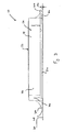
Fig. 1 is a perspective view of a ground surface access assembly; -
Fig. 2 is a perspective view from below of the ground surface access assembly ofFig 1 ; -
Fig. 3 is a side view of the ground surface access assembly; -
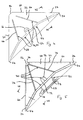
Fig. 4 is a view from above of a cover; -
Fig. 5 is a view from below of the cover offigure 4 ; -
Fig. 6 is a sectional view of part of the cover ofFigs 4 and 5 , as indicated by the section line VI-VI inFigs 4 and 5 . -
Figs 1 to 3 show a groundsurface access assembly 10, theassembly 10 including aframe 14 defining anaccess opening 50 and a pair of substantially identical covers 22 mountable to theframe 14 within theopening 50. - The
frame 14 and thecovers 22 could be formed by casting, and could be formed of cast iron, and could be formed of ductile iron. - Each of the
covers 22 is substantially triangular in plan, having a pair ofcorners 54 which subtend an angle of substantially 45° and a 90°corner 56, eachcover 22 including a relativelylong hypotenuse side 58 which extends between the 45°corners 54 and a pair of relativelyshort sides 60, each of which extend between one of the 45°corners 54 and the 90°corner 56. Eachcover 22 includes amounting 34 projecting downwardly from thelower surface 20 at each of thecorners - Each
cover 22 includes a substantiallyplanar part 24 and areinforcement arrangement 52, thereinforcement arrangement 52 including afirst reinforcement part 16 which projects upwardly from anupper surface 26 of theplanar part 24 and asecond reinforcement part 30 which projects downwardly from alower surface 28 of theplanar part 24. - The
first reinforcement part 16 includes amain beam part 62 which extends substantially along a curved line extending between the two 45°corners 54, a pair ofsecondary reinforcement parts 64 which extend from themain beam part 62 towards the 90°corner 56, and akeyhole reinforcement part 66. - In the embodiment shown, the
first reinforcement part 16 forms a raised, upwardly projectingsurface pattern 70 on theupper surface 26. In other examples, thesurface pattern 70 could also include other projecting elements, which could be in the form of text and/or other shapes, and which could be of a different height to thefirst reinforcement part 16. The other projecting elements would not form part of thefirst reinforcement part 16. - As shown in
figure 6 , thefirst reinforcement part 16 projects upwardly from theupper surface 26 by a first reinforcementpart projection height 68. In one example, the first reinforcement part projection height could be at least 2 mm, and could be less than 6 mm, and optimally could be approximately 4 mm. - The
second reinforcement part 30 includes amain beam part 72 which extends substantially along a curved line extending between themountings 34 of the two 45°corners 54, a pair ofsecondary reinforcement parts 74, which extend from themain beam part 72 towards themounting 34 of the 90°corner 56, and a keyhole reinforcement part 76. - The
reinforcement arrangement 52 also includes other reinforcement features 78 projecting downwardly from thelower surface 28, which could be in the form of auxiliary beams, webs, etc, which do not form part of thesecond reinforcement part 30. - The
planar part 24, thefirst reinforcement part 16 and thesecond reinforcement part 30 are formed integrally. - The shape and location of the
first reinforcement part 16 when viewed in plan as shown inFigs 4 and 5 corresponds with the shape and location of thesecond reinforcement part 30, so that thesecond reinforcement part 30 is located substantially oppositely and below thefirst reinforcement part 16. Thus, the second reinforcement ofmain beam part 72 is substantially directly below the first reinforcementmain beam part 62 as shown infigure 6 , and similarly the second reinforcementsecondary parts 74 are substantially directly below the first reinforcementsecondary parts 64. The applicant has found that this provides the advantage that when subjected to test loading, in which a test load is applied through a pad or plate to the covers 22 above the central part of theopening 50, the first andsecond reinforcement parts first reinforcement part 16 extends the depth of thesecond reinforcement part 30 to increase the effective load-bearing capacity of thecover 22. - In one example, a
first reinforcement part 16 having a first reinforcementpart projection height 68 of approximately 4 mm resulted in movement of the position of the neutral axis in a loading condition upwards by approximately 2 mm, when compared with the position of the neutral axis of a cover without afirst reinforcement part 16, increasing the second moment of area for the portion in tension and resulting in an increase in load bearing capacity of 3.5 tonnes, an increase of 8.5%. The increase in load-bearing capacity permits the designer to reduce the weight of material in thecover 22, resulting in a cost saving. - As shown in
figure 6 , thewidth 80 of thefirst reinforcement part 16 is greater than thewidth 82 of thesecond reinforcement part 30 to allow for a degree of mismatch during the casting process of mould parts. In one example, thewidth 80 of thefirst reinforcement part 16 is approximately 2 mm greater than thewidth 82 of thesecond reinforcement part 30. - The
frame 14 includes a plurality ofsidewalls 18, thesidewalls 18 including anupstanding part 42 and aflange part 44 which extends outwardly from a lower part in use of theupstanding part 42. Theframe 14 includes a plurality ofspacer projections 46 which extend downwardly from and in uselower surface 48 of theflange part 44. In the embodiment shown infigure 2 , theframe 14 includes fourspacer projections 46, each spacer projection 40 being located at a corner of theframe 14. Eachspacer projection 46 extends inwardly from an outermost edge of theflange part 44 to a position which is located outboard of theupstanding part 42 in the vertical plane. This provides the advantage at that, when stacked, theupstanding part 42 of oneframe 14 can locate between thespacer projections 46 of anadjacent frame 14, providing a degree of interlock betweenadjacent frames 14 in a stack, and thus improving the stability of the stack, and also providing a degree of nesting between frames, reducing the overall height of the stack and increasing the storage density. - Each
spacer projection 46 projects by a spacer projection height 86. The spacer projection height 86 could be at least 5 mm, and could be no more than 15 mm. In one example, thespacer projection height 46 could be approximately 10 mm. -
Figure 3 shows the groundsurface access assembly 10 in use. Theframe 14 is located on asupport surface 20. Thespacer projections 46 space thesidewalls 18 from thesupport surface 20. A gap 84 is defined between thespacer projections 46, thelower surface 48 of theflange part 44 and thesupport surface 20. - In use in construction, a bedding layer of a settable material such as mortar, resin concrete or an epoxy material is applied to the
support surface 20, and theframe 14 located in the settable material so that thespacer projections 46 contact thesupport surface 20. The settable material fills the gap 84. The gap 84 is arranged so that, when filled, the settable material conforms to a specified minimum thickness. - The
spacer projections 46 permit a reduction in frame material weight, while permitting the overall height of the frame to be maintained, so that the depth of construction of the groundsurface access assembly 10 of the invention is similar to that of a conventional ground surface access assembly. In one example, the overall height of a conventional frame is approximately 102 mm, while in the frame of the invention, the height of thesidewalls 18 could be approximately 92 mm and the spacer projection height 86 could be approximately 10 mm. - The requirement to stack ground surface access assemblies on top of each other imposes a further constraint upon the designer, in that it is important for stability that when stacked, adjacent assemblies make contact between respective sidewalls, rather than between the downwardly extending reinforcement parts and upper surfaces of covers, which could cause rocking and instability. Providing
spacer projections 46 which permit nesting of adjacent assemblies would, in the absence of any other modification, increase the risk of contact between cover parts rather than sidewalls. The provision of thereinforcement arrangement 52 of the present invention permits a reduction in projection height of the second reinforcementmain beam part 72, reducing the risk of contact between cover parts. Thus, there is a synergy between the provision of thespacer projections 46 and the provision of thereinforcement arrangement 52. - In one example, a ground surface access assembly conforming to class D400 of European Standard EN 124 which included
spacer projections 46 and first andsecond reinforcement parts - Various modifications could be made without departing from the scope of the invention. The assembly could include any suitable number of covers, and could include a single cover. The assembly, the frame and the cover or covers could be of any suitable size, shape and configuration. For example, when viewed in plan, the assembly could be substantially triangular, square, rectangular or circular in shape. The assembly, the frame and the cover or covers could be formed by any suitable method or combination of methods, and could be formed of any suitable material, such as aluminium or plastics.
- The reinforcement arrangement could include any suitable number of reinforcement parts, and the reinforcement parts could include any suitable number of elements, of any suitable size, shape or configuration.
- The assembly could include any suitable number of spacer projections, which could be of any suitable size, shape or configuration. To ensure non-rock mounting, the minimum number of spacer projections should be three.
- There is thus provided a ground surface access assembly including a cover and a frame which provides a number of advantages over conventional assemblies. The combination of the reinforcement arrangement of the invention with the spacer projections permits a significant reduction in weight to be achieved, reducing both manufacturing and transport costs and reducing handling risks on site, while providing an access assembly which can be manufactured using conventional materials and methods, and storage density is also increased, reducing storage costs.
Claims (15)
- A cover (22) for a ground surface access assembly (10), characterised in that the assembly includes a frame (14) defining an access opening (50), the cover mountable to the frame within the opening, the cover including a substantially planar part (24) and a reinforcement arrangement (52), the reinforcement arrangement including a first reinforcement part (16) projecting upwardly from an upper surface (26) in use of the planar part and a second reinforcement part (30) projecting downwardly from a lower surface (28) in use of the planar part.
- A cover according to claim 1, in which the cover includes a raised, upwardly projecting surface pattern (70) which is formed on the upper surface, and the first reinforcement part forms at least part of the raised pattern.
- A cover according to claims 1 or 2, in which the shape and location of the first reinforcement part when viewed in plan corresponds with the shape and location of the second reinforcement part, so that the second reinforcement part is located substantially oppositely and below the first reinforcement part.
- A cover according to any of the preceding claims, in which the maximum width of the first reinforcement part is greater than the maximum width of the second reinforcement part.
- A cover according to any of the preceding claims, in which the first reinforcement part projects above the upper surface by a first reinforcement part projection height of at least 2mm.
- A cover according to any of the preceding claims, in which the first reinforcement part projection height is less than 6mm.
- A frame (14) for a ground surface access assembly (10), characterised in that the frame includes a plurality of side walls (18) and a plurality of spacer projections (46), which extend downwardly from the side walls to space the side walls from a support surface (20).
- A frame according to claim 7, in which the side walls include an upstanding part (42), and a flange part (44) which extends outwardly from a lower part in use of the upstanding part, and each spacer projection extends from an in use lower surface (48) of the flange part (44).
- A frame according to claim 8, in which the spacer projections are located outboard of the upstanding part, so that when stacked the upstanding part of one frame locates between the spacer projections of an adjacent frame.
- A frame according to any of claims 7 to 9, in which the frame includes at least three spacer projections.
- A frame according to any of claims 7 to 10, in which each spacer projection projects by a spacer projection height (86) of at least 5mm.
- A frame according to any of claims 7 to 11, in which the spacer projection height is not more than 15mm.
- A frame according to any of claims 7 to 12, in which the spacer projection height is approximately 10 mm.
- A ground surface access assembly characterised in that the assembly includes a frame (14) defining an access opening (50) and a cover (22) mountable to the frame within the opening, in which the cover is as defined in any of claims 1 to 6, and the frame is as defined in any of claims 7 to 13.
- An assembly according to claim 14, in which the assembly includes a plurality of covers, and may include two covers.
Applications Claiming Priority (1)
| Application Number | Priority Date | Filing Date | Title |
|---|---|---|---|
| GB0903821A GB2468480B (en) | 2009-03-06 | 2009-03-06 | Ground surface access assemblies |
Publications (2)
| Publication Number | Publication Date |
|---|---|
| EP2246483A1 true EP2246483A1 (en) | 2010-11-03 |
| EP2246483B1 EP2246483B1 (en) | 2013-07-10 |
Family
ID=40600567
Family Applications (1)
| Application Number | Title | Priority Date | Filing Date |
|---|---|---|---|
| EP20100250420 Active EP2246483B1 (en) | 2009-03-06 | 2010-03-08 | Ground surface access assemblies |
Country Status (2)
| Country | Link |
|---|---|
| EP (1) | EP2246483B1 (en) |
| GB (1) | GB2468480B (en) |
Families Citing this family (1)
| Publication number | Priority date | Publication date | Assignee | Title |
|---|---|---|---|---|
| GB201415380D0 (en) * | 2014-08-29 | 2014-10-15 | Wrekin Holdings Ltd | Ground surface access assemblies |
Citations (3)
| Publication number | Priority date | Publication date | Assignee | Title |
|---|---|---|---|---|
| EP0808951A1 (en) * | 1996-05-24 | 1997-11-26 | Norinco | Hinged manhole cover on a frame |
| EP1752584A2 (en) * | 2005-08-02 | 2007-02-14 | Atlanta Impex Limited | Access cover |
| EP1870524A2 (en) * | 2006-06-20 | 2007-12-26 | Wrekin Welding Fabrication & Engineering Limited | Surface access assemblies |
Family Cites Families (3)
| Publication number | Priority date | Publication date | Assignee | Title |
|---|---|---|---|---|
| GB247853A (en) * | 1925-09-04 | 1926-02-25 | Francis Shanley | Improvements in manholes |
| GB2374373B (en) * | 2001-04-12 | 2005-02-09 | Wrekin Welding & Fabrication E | Ground surface access assemblies |
| GB2444769A (en) * | 2006-12-12 | 2008-06-18 | Wrekin Welding & Fabrication E | Ground surface access assembly |
-
2009
- 2009-03-06 GB GB0903821A patent/GB2468480B/en not_active Expired - Fee Related
-
2010
- 2010-03-08 EP EP20100250420 patent/EP2246483B1/en active Active
Patent Citations (3)
| Publication number | Priority date | Publication date | Assignee | Title |
|---|---|---|---|---|
| EP0808951A1 (en) * | 1996-05-24 | 1997-11-26 | Norinco | Hinged manhole cover on a frame |
| EP1752584A2 (en) * | 2005-08-02 | 2007-02-14 | Atlanta Impex Limited | Access cover |
| EP1870524A2 (en) * | 2006-06-20 | 2007-12-26 | Wrekin Welding Fabrication & Engineering Limited | Surface access assemblies |
Also Published As
| Publication number | Publication date |
|---|---|
| GB0903821D0 (en) | 2009-04-22 |
| GB2468480A (en) | 2010-09-15 |
| EP2246483B1 (en) | 2013-07-10 |
| GB2468480B (en) | 2014-01-08 |
Similar Documents
| Publication | Publication Date | Title |
|---|---|---|
| AU2014401974B2 (en) | Percolation block element, percolation block, and transport unit | |
| EP1207987B1 (en) | Lost mould element for manufacturing reinforced concrete flat slabs | |
| CA2840139C (en) | Manhole cover | |
| EP3088319A1 (en) | Pallet | |
| EP2246483B1 (en) | Ground surface access assemblies | |
| CN111255639A (en) | Bearing structural member for wind power blade and preparation method thereof | |
| US7866915B2 (en) | Covering for an access aperture, and related assemblies | |
| KR102292294B1 (en) | Construction method of internal reinforcement of bridge girder | |
| CA2298535A1 (en) | A frame for a manhole cover | |
| GB2477296A (en) | Wall section for a free standing wall | |
| KR101916744B1 (en) | Upper structure of bridge with improved stiffness, and Bridge construction method using it | |
| EP2792794B1 (en) | Ground surface access assemblies | |
| KR101486140B1 (en) | Block frame | |
| JP2010133111A (en) | Cover member for water storage tank, and water storage tank | |
| WO2008007981A1 (en) | Access cover | |
| GB2376495A (en) | Frame arrangement for ground surface access assembly | |
| KR102061515B1 (en) | Synthetic girders with increased flexural stiffness and section modulus, temporary structures and bridges using composite girders | |
| US20220168923A1 (en) | Precast concrete pullbox with knockout section | |
| KR20140120097A (en) | Manhole cover structure with plastic body | |
| JP5588328B2 (en) | Lid fixing structure and lid fixing method | |
| CN218617723U (en) | Packaging pallet | |
| US9809935B2 (en) | Rail of a drainage channel | |
| JP2004161319A (en) | Carrying container | |
| KR20220025763A (en) | Deep Depth Deck-Plate And Reinforcement Composition Used for the Same | |
| KR20230134384A (en) | Slab deck and structure system including slab |
Legal Events
| Date | Code | Title | Description |
|---|---|---|---|
| PUAI | Public reference made under article 153(3) epc to a published international application that has entered the european phase |
Free format text: ORIGINAL CODE: 0009012 |
|
| AK | Designated contracting states |
Kind code of ref document: A1 Designated state(s): AT BE BG CH CY CZ DE DK EE ES FI FR GB GR HR HU IE IS IT LI LT LU LV MC MK MT NL NO PL PT RO SE SI SK SM TR |
|
| AX | Request for extension of the european patent |
Extension state: AL BA ME RS |
|
| 17P | Request for examination filed |
Effective date: 20110503 |
|
| GRAP | Despatch of communication of intention to grant a patent |
Free format text: ORIGINAL CODE: EPIDOSNIGR1 |
|
| GRAS | Grant fee paid |
Free format text: ORIGINAL CODE: EPIDOSNIGR3 |
|
| GRAA | (expected) grant |
Free format text: ORIGINAL CODE: 0009210 |
|
| AK | Designated contracting states |
Kind code of ref document: B1 Designated state(s): AT BE BG CH CY CZ DE DK EE ES FI FR GB GR HR HU IE IS IT LI LT LU LV MC MK MT NL NO PL PT RO SE SI SK SM TR |
|
| REG | Reference to a national code |
Ref country code: GB Ref legal event code: FG4D |
|
| REG | Reference to a national code |
Ref country code: AT Ref legal event code: REF Ref document number: 621064 Country of ref document: AT Kind code of ref document: T Effective date: 20130715 Ref country code: CH Ref legal event code: EP |
|
| REG | Reference to a national code |
Ref country code: IE Ref legal event code: FG4D |
|
| REG | Reference to a national code |
Ref country code: DE Ref legal event code: R096 Ref document number: 602010008388 Country of ref document: DE Effective date: 20130905 |
|
| PG25 | Lapsed in a contracting state [announced via postgrant information from national office to epo] |
Ref country code: SI Free format text: LAPSE BECAUSE OF FAILURE TO SUBMIT A TRANSLATION OF THE DESCRIPTION OR TO PAY THE FEE WITHIN THE PRESCRIBED TIME-LIMIT Effective date: 20130710 |
|
| REG | Reference to a national code |
Ref country code: AT Ref legal event code: MK05 Ref document number: 621064 Country of ref document: AT Kind code of ref document: T Effective date: 20130710 |
|
| REG | Reference to a national code |
Ref country code: NL Ref legal event code: VDEP Effective date: 20130710 |
|
| REG | Reference to a national code |
Ref country code: LT Ref legal event code: MG4D |
|
| PG25 | Lapsed in a contracting state [announced via postgrant information from national office to epo] |
Ref country code: AT Free format text: LAPSE BECAUSE OF FAILURE TO SUBMIT A TRANSLATION OF THE DESCRIPTION OR TO PAY THE FEE WITHIN THE PRESCRIBED TIME-LIMIT Effective date: 20130710 Ref country code: SE Free format text: LAPSE BECAUSE OF FAILURE TO SUBMIT A TRANSLATION OF THE DESCRIPTION OR TO PAY THE FEE WITHIN THE PRESCRIBED TIME-LIMIT Effective date: 20130710 Ref country code: CY Free format text: LAPSE BECAUSE OF FAILURE TO SUBMIT A TRANSLATION OF THE DESCRIPTION OR TO PAY THE FEE WITHIN THE PRESCRIBED TIME-LIMIT Effective date: 20130710 Ref country code: LT Free format text: LAPSE BECAUSE OF FAILURE TO SUBMIT A TRANSLATION OF THE DESCRIPTION OR TO PAY THE FEE WITHIN THE PRESCRIBED TIME-LIMIT Effective date: 20130710 Ref country code: NO Free format text: LAPSE BECAUSE OF FAILURE TO SUBMIT A TRANSLATION OF THE DESCRIPTION OR TO PAY THE FEE WITHIN THE PRESCRIBED TIME-LIMIT Effective date: 20131010 Ref country code: IS Free format text: LAPSE BECAUSE OF FAILURE TO SUBMIT A TRANSLATION OF THE DESCRIPTION OR TO PAY THE FEE WITHIN THE PRESCRIBED TIME-LIMIT Effective date: 20131110 Ref country code: HR Free format text: LAPSE BECAUSE OF FAILURE TO SUBMIT A TRANSLATION OF THE DESCRIPTION OR TO PAY THE FEE WITHIN THE PRESCRIBED TIME-LIMIT Effective date: 20130710 Ref country code: BE Free format text: LAPSE BECAUSE OF FAILURE TO SUBMIT A TRANSLATION OF THE DESCRIPTION OR TO PAY THE FEE WITHIN THE PRESCRIBED TIME-LIMIT Effective date: 20130710 Ref country code: PT Free format text: LAPSE BECAUSE OF FAILURE TO SUBMIT A TRANSLATION OF THE DESCRIPTION OR TO PAY THE FEE WITHIN THE PRESCRIBED TIME-LIMIT Effective date: 20131111 |
|
| PG25 | Lapsed in a contracting state [announced via postgrant information from national office to epo] |
Ref country code: FI Free format text: LAPSE BECAUSE OF FAILURE TO SUBMIT A TRANSLATION OF THE DESCRIPTION OR TO PAY THE FEE WITHIN THE PRESCRIBED TIME-LIMIT Effective date: 20130710 Ref country code: GR Free format text: LAPSE BECAUSE OF FAILURE TO SUBMIT A TRANSLATION OF THE DESCRIPTION OR TO PAY THE FEE WITHIN THE PRESCRIBED TIME-LIMIT Effective date: 20131011 Ref country code: PL Free format text: LAPSE BECAUSE OF FAILURE TO SUBMIT A TRANSLATION OF THE DESCRIPTION OR TO PAY THE FEE WITHIN THE PRESCRIBED TIME-LIMIT Effective date: 20130710 Ref country code: LV Free format text: LAPSE BECAUSE OF FAILURE TO SUBMIT A TRANSLATION OF THE DESCRIPTION OR TO PAY THE FEE WITHIN THE PRESCRIBED TIME-LIMIT Effective date: 20130710 Ref country code: NL Free format text: LAPSE BECAUSE OF FAILURE TO SUBMIT A TRANSLATION OF THE DESCRIPTION OR TO PAY THE FEE WITHIN THE PRESCRIBED TIME-LIMIT Effective date: 20130710 Ref country code: ES Free format text: LAPSE BECAUSE OF FAILURE TO SUBMIT A TRANSLATION OF THE DESCRIPTION OR TO PAY THE FEE WITHIN THE PRESCRIBED TIME-LIMIT Effective date: 20131021 |
|
| PG25 | Lapsed in a contracting state [announced via postgrant information from national office to epo] |
Ref country code: SK Free format text: LAPSE BECAUSE OF FAILURE TO SUBMIT A TRANSLATION OF THE DESCRIPTION OR TO PAY THE FEE WITHIN THE PRESCRIBED TIME-LIMIT Effective date: 20130710 Ref country code: CZ Free format text: LAPSE BECAUSE OF FAILURE TO SUBMIT A TRANSLATION OF THE DESCRIPTION OR TO PAY THE FEE WITHIN THE PRESCRIBED TIME-LIMIT Effective date: 20130710 Ref country code: DK Free format text: LAPSE BECAUSE OF FAILURE TO SUBMIT A TRANSLATION OF THE DESCRIPTION OR TO PAY THE FEE WITHIN THE PRESCRIBED TIME-LIMIT Effective date: 20130710 Ref country code: EE Free format text: LAPSE BECAUSE OF FAILURE TO SUBMIT A TRANSLATION OF THE DESCRIPTION OR TO PAY THE FEE WITHIN THE PRESCRIBED TIME-LIMIT Effective date: 20130710 Ref country code: RO Free format text: LAPSE BECAUSE OF FAILURE TO SUBMIT A TRANSLATION OF THE DESCRIPTION OR TO PAY THE FEE WITHIN THE PRESCRIBED TIME-LIMIT Effective date: 20130710 |
|
| PLBE | No opposition filed within time limit |
Free format text: ORIGINAL CODE: 0009261 |
|
| STAA | Information on the status of an ep patent application or granted ep patent |
Free format text: STATUS: NO OPPOSITION FILED WITHIN TIME LIMIT |
|
| PG25 | Lapsed in a contracting state [announced via postgrant information from national office to epo] |
Ref country code: IT Free format text: LAPSE BECAUSE OF FAILURE TO SUBMIT A TRANSLATION OF THE DESCRIPTION OR TO PAY THE FEE WITHIN THE PRESCRIBED TIME-LIMIT Effective date: 20130710 |
|
| 26N | No opposition filed |
Effective date: 20140411 |
|
| REG | Reference to a national code |
Ref country code: DE Ref legal event code: R097 Ref document number: 602010008388 Country of ref document: DE Effective date: 20140411 |
|
| PG25 | Lapsed in a contracting state [announced via postgrant information from national office to epo] |
Ref country code: LU Free format text: LAPSE BECAUSE OF FAILURE TO SUBMIT A TRANSLATION OF THE DESCRIPTION OR TO PAY THE FEE WITHIN THE PRESCRIBED TIME-LIMIT Effective date: 20140308 |
|
| REG | Reference to a national code |
Ref country code: CH Ref legal event code: PL |
|
| REG | Reference to a national code |
Ref country code: IE Ref legal event code: MM4A |
|
| PG25 | Lapsed in a contracting state [announced via postgrant information from national office to epo] |
Ref country code: IE Free format text: LAPSE BECAUSE OF NON-PAYMENT OF DUE FEES Effective date: 20140308 Ref country code: CH Free format text: LAPSE BECAUSE OF NON-PAYMENT OF DUE FEES Effective date: 20140331 Ref country code: LI Free format text: LAPSE BECAUSE OF NON-PAYMENT OF DUE FEES Effective date: 20140331 |
|
| PG25 | Lapsed in a contracting state [announced via postgrant information from national office to epo] |
Ref country code: MT Free format text: LAPSE BECAUSE OF FAILURE TO SUBMIT A TRANSLATION OF THE DESCRIPTION OR TO PAY THE FEE WITHIN THE PRESCRIBED TIME-LIMIT Effective date: 20130710 |
|
| REG | Reference to a national code |
Ref country code: FR Ref legal event code: PLFP Year of fee payment: 7 |
|
| PG25 | Lapsed in a contracting state [announced via postgrant information from national office to epo] |
Ref country code: SM Free format text: LAPSE BECAUSE OF FAILURE TO SUBMIT A TRANSLATION OF THE DESCRIPTION OR TO PAY THE FEE WITHIN THE PRESCRIBED TIME-LIMIT Effective date: 20130710 |
|
| PG25 | Lapsed in a contracting state [announced via postgrant information from national office to epo] |
Ref country code: MC Free format text: LAPSE BECAUSE OF FAILURE TO SUBMIT A TRANSLATION OF THE DESCRIPTION OR TO PAY THE FEE WITHIN THE PRESCRIBED TIME-LIMIT Effective date: 20130710 |
|
| PG25 | Lapsed in a contracting state [announced via postgrant information from national office to epo] |
Ref country code: BG Free format text: LAPSE BECAUSE OF FAILURE TO SUBMIT A TRANSLATION OF THE DESCRIPTION OR TO PAY THE FEE WITHIN THE PRESCRIBED TIME-LIMIT Effective date: 20130710 |
|
| PG25 | Lapsed in a contracting state [announced via postgrant information from national office to epo] |
Ref country code: TR Free format text: LAPSE BECAUSE OF FAILURE TO SUBMIT A TRANSLATION OF THE DESCRIPTION OR TO PAY THE FEE WITHIN THE PRESCRIBED TIME-LIMIT Effective date: 20130710 Ref country code: HU Free format text: LAPSE BECAUSE OF FAILURE TO SUBMIT A TRANSLATION OF THE DESCRIPTION OR TO PAY THE FEE WITHIN THE PRESCRIBED TIME-LIMIT; INVALID AB INITIO Effective date: 20100308 |
|
| REG | Reference to a national code |
Ref country code: FR Ref legal event code: PLFP Year of fee payment: 8 |
|
| REG | Reference to a national code |
Ref country code: FR Ref legal event code: PLFP Year of fee payment: 9 |
|
| PG25 | Lapsed in a contracting state [announced via postgrant information from national office to epo] |
Ref country code: MK Free format text: LAPSE BECAUSE OF FAILURE TO SUBMIT A TRANSLATION OF THE DESCRIPTION OR TO PAY THE FEE WITHIN THE PRESCRIBED TIME-LIMIT Effective date: 20130710 |
|
| PGFP | Annual fee paid to national office [announced via postgrant information from national office to epo] |
Ref country code: DE Payment date: 20180403 Year of fee payment: 9 |
|
| REG | Reference to a national code |
Ref country code: DE Ref legal event code: R119 Ref document number: 602010008388 Country of ref document: DE |
|
| PG25 | Lapsed in a contracting state [announced via postgrant information from national office to epo] |
Ref country code: DE Free format text: LAPSE BECAUSE OF NON-PAYMENT OF DUE FEES Effective date: 20191001 |
|
| PGFP | Annual fee paid to national office [announced via postgrant information from national office to epo] |
Ref country code: FR Payment date: 20230331 Year of fee payment: 14 |
|
| PGFP | Annual fee paid to national office [announced via postgrant information from national office to epo] |
Ref country code: GB Payment date: 20230406 Year of fee payment: 14 |
|
| PGFP | Annual fee paid to national office [announced via postgrant information from national office to epo] |
Ref country code: GB Payment date: 20240329 Year of fee payment: 15 |