EP2246479A1 - Equipment for the construction of piles - Google Patents
Equipment for the construction of piles Download PDFInfo
- Publication number
- EP2246479A1 EP2246479A1 EP10159438A EP10159438A EP2246479A1 EP 2246479 A1 EP2246479 A1 EP 2246479A1 EP 10159438 A EP10159438 A EP 10159438A EP 10159438 A EP10159438 A EP 10159438A EP 2246479 A1 EP2246479 A1 EP 2246479A1
- Authority
- EP
- European Patent Office
- Prior art keywords
- tool
- compaction
- shape
- tooth
- excavation
- Prior art date
- Legal status (The legal status is an assumption and is not a legal conclusion. Google has not performed a legal analysis and makes no representation as to the accuracy of the status listed.)
- Granted
Links
Images


Classifications
-
- E—FIXED CONSTRUCTIONS
- E02—HYDRAULIC ENGINEERING; FOUNDATIONS; SOIL SHIFTING
- E02D—FOUNDATIONS; EXCAVATIONS; EMBANKMENTS; UNDERGROUND OR UNDERWATER STRUCTURES
- E02D5/00—Bulkheads, piles, or other structural elements specially adapted to foundation engineering
- E02D5/22—Piles
- E02D5/34—Concrete or concrete-like piles cast in position ; Apparatus for making same
- E02D5/36—Concrete or concrete-like piles cast in position ; Apparatus for making same making without use of mouldpipes or other moulds
-
- E—FIXED CONSTRUCTIONS
- E02—HYDRAULIC ENGINEERING; FOUNDATIONS; SOIL SHIFTING
- E02D—FOUNDATIONS; EXCAVATIONS; EMBANKMENTS; UNDERGROUND OR UNDERWATER STRUCTURES
- E02D7/00—Methods or apparatus for placing sheet pile bulkheads, piles, mouldpipes, or other moulds
- E02D7/22—Placing by screwing down
Abstract
Description
- The present invention relates to an excavation and compaction equipment for the construction of piles.
- From the
European patent EP 0 228 138 it is known an excavation and compaction equipment for the construction of piles comprising an antenna, a rotary table slidingly mounted along the antenna, a drilling rod actuated by the rotary table, and a tool, which is mounted at a lower end of the drilling rod itself. - The tool comprises, in its turn, a central body with an external diameter equal to an external diameter of the rod, an excavation screw integral with the central body, and a displacer element arranged along the rod immediately on the screw for compacting the walls of the excavation during the drilling.
- As it is also described in the patent, the equipment undergoes a torsional moment on the drilling rod and a thrust on the excavation screw relatively elevated because the mass of the soil to be compacted during the excavation by the displacer element is of significant relevance and exerts also a strong resistance to the advancement of the tool in the soil itself. A similar solicitation brings to the need for making an equipment of huge size and, also, to the need of adequate motorizations, whose power, however, is fully used only during the drilling/compaction phase, but not during the extraction of the tool from the excavation, that is during the filling by means of concrete injection through the tool itself.
- When a pile is carried out according to this technology without removal of soil, it is important to obtain a good consolidation of the walls of the excavation and a good anchoring of the pile in the soil.
- In this regard, for increasing the contact surface between pile and soil, a screw groove is carried out in the cylindrical wall creating the so-called "screw displacement pile" or screw pile. During the casting phase, the concrete flows in all the cavity by filling also the helical grooving which has been just grooved in the soil, giving to the pile a screwed shape which improves the anchoring to the soil and therefore its relative carrying capacity.
- Furthermore, the screw pile permits a huge saving on the total quantity of the concrete used because with the same carrying capacity the diameter of the central shaft can be appreciably lower with respect to the one of the piles compacted with a cylindrical surface.
- From the
European patent EP 1 277 887 B1 it is known an equipment for constructing screw piles, but the carrying out of the compaction during the descent phase falls in the above mentioned drawbacks (big thrusts and torques required contemporarily for the advancement, machines having a significant tonnage for bearing the enormous thrusts). Furthermore, the tooth carries out the grooving both during the descent and during the ascent phase when filling with concrete, by increasing at least the relative consumption and the possibility of ostacles or breakings during the descent. On the other hand, during the ascent, the concrete immediately fills the grooving giving to the pile the screw shape, during the descent the groove is probably filled by the following compaction giving thus to the excavation wall a non-homogeneous compaction surface. - From the European patent
EP 1726718 A1 it is known the possibility of carrying out piles through compaction of the soil during the phase of ascent with inversion of the rotation direction, but this does not provide for the possibility of carrying out screw piles. - The standard tools for the compaction in advancement are characterized in that they all have a lower conical tract necessary for the first penetration and enlarging of the soil. This part is provided with screw which makes the material to go back up to the upper tract (characterized in that it has the maximum diameter) until it generates the compaction at the desired diameter. During the ascent, these tools must absolutely continue rotating in the same direction of the advancement phase, because otherwise the soil contained in the conical tract, being in the lower part of the casting, would contaminate the casting drastically reducing the strength of the pile obtained. On the other hand, the technique of tensioned compaction requires a counter-rotation for separating the part of the casting from the one wherein it is contained the soil to be compacted.
- The purpose of the present invention is to provide an excavation and compaction equipment for the construction of screw piles, which is free from the above described disadvantages.
- In order to reach these and other purposes which will be better understood hereinafter, the present invention proposes to make an excavation and compaction equipment for the construction of screw piles according to
claim 1. - The invention will be now described with reference to the attached drawings, which show a non-limiting form of embodiment, wherein:
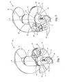
- in
figure 1 and2 it is shown the equipment according to the invention from a bottom and lateral perspective view respectively, in excavation condition (descent); - in
figure 3 and4 it is shown the same equipment offigure 1 and2 in the same perspective views, but in compaction condition (ascent); - in
figure 5-10 it is shown the equipment according to the invention, from a bottom view in the different working conditions. - Excavation and
compaction equipment 10 for the construction of piles shown in the figures is commonly constituted by acentral shaft 11 around which develops at least ascrew 12 provided withcompaction surface 13 and ending with a substantiallysemicircular base 14. - Around the base rotates a
plate 15 substantially semicircular too which, in excavation condition (fig. 1 and2 ), assumes a reclosed position substantially fitting withbase 14, underneath it, whereas in the compaction condition (fig. 3 and4 ) assumes an open position for which, together withbase 14, provides a substantially circular bottom surface and apt to divide the underlying zone used for the pile casting, from the overhanging one used for the compaction. - Furthermore, on
plate 15 are also applieddigging teeth 16, whereas atbase 14 is applied acylindrical appendix 17 having adoor 18 for the outlet of the concrete. - According to the invention, a
tool 19 is hinged onpivot 20 to the lower face ofplate 15 in correspondence with afirst stop 21 fixed to the plate too. - Eventually, a
second stop 22 and acam surface 23 are integral withshaft 11 by the part ofappendix 17 which is subjected to a rotation relative with respect toplate 15. - In the descent or excavation configuration, shown in
figure 1 ,2 and5 ,tooth 19 will find itself reclosed inside the excavation diameter, with itsseat 24 engaged intosecond striker 22 whereasplate 15 is open for the passage of debris alongscrew 12, toward the top of the equipment. - In the ascent or compaction configuration, shown in
figure 3 ,4 and10 ,tooth 19 will find itself open on the outside of the excavation diameter, after having rotated on hingingaxis 20 up to the contact with thefirst stop 21, and withplate 15 closed, that is rotated for creating a circular surface withbase 14, for obstructing the passage of debris towards the lower zone used for the casting. - The outlet of
tooth 19 from the inner shape of the tool is produced by the rotation itself ofplate 15 with respect to the parts integral withshaft 11 which, by forcing the contact betweensecond stop 22 andcorresponding cavity 24 ontooth 19 generates the rotation. - In fact, at the end of the descent phase, before going back up, is anyway performed the inversion of the rotation of axis A of the equipment for causing the closing of
plate 15 and thus permitting the separation between the lower casting zone fromopenable door 18 and the upper compaction zone containing the soil. - As it is shown in
figure 4 , during the ending phase of outlet oftooth 19,cam 23 retains the tooth in locked position, preventing its return rotation. - The passage from the descent condition (excavation) to the ascent one (compaction) is shown in
figures 5-10 wherein it can be seen that when plate 15 (fig. 6 ) begins to rotate for reclosing,tooth 19 leveragingsecond stop 22 begins to protrude from the shape of the equipment by rotating around itspivot 20 and little by little protrudes even more asplate 15 rotates (figures 7 and 8 ), going away fromsecond stop 22. - Finally, (
figures 9 and 10 )tooth 19 begins the sliding oncam 23 striking against the first stop providing the locking of the teeth in this position tillplate 15 begins again the rotation in opening. Thefirst stop 21 has also the function of supportingtooth 19 during the excavation of the grooving, collaborating to the total resistance against the shearing forces. The counter-rotation of onlytooth 19 is instead not permitted by the particular shape of its ending surface in contact withcam 23. - In order to carry out a screw pile shape with the optimal bearing, it is necessary to control the ascent (casting phase) by correlating the rotation speed and the one of the ascent in such a way as to obtain a constant pitch of the helical part. For doing this, a plc control device manages the drilling parameters on the machine by directly monitoring the rotation speed and the ascent speed, correlating them to the quantity of concrete material injected per unit time and retroacting controls on the pump for permitting the constancy of the pitches .
- The possibility of carrying out screw piles by compacting the soil during the ascent of the tool permits to use a traction force much higher than the one applicable during the thrust, with equal weight of the machine permitting, therefore, also the use of machines having reduced size, contributing to the economy of the excavation, and to the easiness of transport of the equipment.
- Furthermore, the movable tooth allows to carry out a faster excavation during the descent and without inconvenients of possible breakings due to the presence of stones or erratic blocks.
- During the excavation phase, in fact, the drilling speed must be the fastest possible, hence the high speeds solicit to a greater extent all the parts in contact with the soil. During the ascent phase, instead, the speed is determined by the maximum pump delivery and, generally, is very slow, hence the protruding tooth is less solicited and can be simplified.
- It is clear that on the same solution of compaction tool which works in tension, it is possible to apply a fixed tooth which always remains protruding for all the phases, but the advantages of a structure which penetrates in the soil without inconvenients of breakings and consequent machine downtimes would be lost.
- In this kind of excavation equipment, taking place anyhow the rotation of the plate and having to keep inverted the direction of rotation during all the ascent phase, it is probable that the grooving carried out during the descent can disturb the one which is being executed during the ascent.
- In fact, in the compaction and casting phase, the ascent must be adequately correlated to all the operating parameters and the presence of a previously executed grooving and having the same sense and direction of the one which is being made, can deflect
tooth 19 by forcing it to go along a path not wanted. These deviations would bring the tool to work with consequent cracks, changes of direction or adjustments to the higher pitch, which would determine a scarce pile quality. In other cases, the presence of a previous grooving could constitute a preferential path for the material injected during the casting phase which would find thus an alternative escape way, flowing towards the upper part. - For these reasons, it is thought that the fixed tooth solution, even if practicable, is not to be preferred.
- The movable tooth is also removable for facilitating the interchangeability in case of wears. The fact that it is removable, permits also to replace it with another which has a different shape, for instance with higher or lower thicknesses for obtaining a "crest" of the screw pile more or less solid. In fact, this one has to be correlated to the kind of soil and to the ascent pitch in such a way as to have a proportion between the section wherein it shearing works the soil (corresponding to the lateral surface comprised between two adjacent crests of cemented screw pile) and the one wherein it shearing works the concrete (crest section of the cemented screw pile).
-
Teeth 19 can be two teeth opposed for balancing the thrusts and obtaining a double spiral for the higher advantage of the carrying capacity and of the saving on the concrete (in this case it is possible to reduce even more the diameter of the central shaft). - Eventually, it is to be noted that the tooth/teeth can also slide between a retracted position within the shape of the tool and one extracted from the shape itself; in fact, it is not important to rotate or translate or anyhow move
tooth 19, but to allow that at least in the compaction condition it protrudes from the shape of the tool.
Claims (7)
- Excavation and compaction equipment for the construction of piles comprising a drilling rod rotating around a rotation axis (A) and a tool (10) mounted at a lower end of the drilling rod; the tool comprising:- a hollow central shaft (11) and provided at its lower end (17) with a door (18) for the outlet of the concrete;- at least a screw (12) integral with the shaft (11);- means for compaction (13) positioned along the screw (12);- a base (14) of substantially semicircular shape made at the lower end of the screw; (12);- at least a plate (15) of a shape such that it superimposes under the base (14) and rotates relatively around the shaft (11) for alternatively assuming an open position, in condition of excavation (descent) wherein it superimposes on the base, and a reclosed position, in condition of compaction (ascent) wherein it forms a surface substantially circular with the base (14);- excavation teeth (16) fixed to the lower end of the tool;
the equipment being characterized in that at least an additional tooth (19) is constrained to the plate (15) that during at least the phase of casting is outside the shape of the tool in the condition of compaction (ascent). - Equipment according to claim 1 wherein the tooth (19) is movable between two extreme positions wherein one inside the shape of the tool in the condition of excavation (descent) and one outside the shape of the tool in the condition of compaction (ascent).
- Equipment according to claim 1 wherein the tooth (19) is rotating between two extreme positions wherein one inside the shape of the tool in the condition of excavation (descent) and one outside the shape of the tool in the condition of compaction (ascent); being provided means for blocking the tooth in said two extreme positions in a releasable way.
- Equipment according to claim 3 characterized in that the means for blocking the tooth (19) are constituted:- by a stop (22) of the shaft (11) wherein it inserts in a seat (24) of the tooth (19) in a releasable way when it is in the position inside the shape of the tool (descent); and- by a cam (23) of the shaft (11) along which the tooth slides blocking the rotation around the pivot (20) and by a stop (21) of the plate (15) against which the tooth abuts when it is in the position outside the shape of the tool (ascent).
- Equipment according to claim 1 characterized in that the tooth (19) is removable and adaptable to all the typologies of the ground.
- Equipment according to claim 1 characterized in that the teeth (19) are two and work one against the other for balancing the cut stresses.
- Equipment according to claim 1 characterized in that it provides a PLC control System that records the parameters of rotation speed, ascent speed and flow rate of compacted material and permits the control of the parameters of the machine and/or the pump for obtaining the required shape of the spiral pile.
Applications Claiming Priority (1)
| Application Number | Priority Date | Filing Date | Title |
|---|---|---|---|
| ITTO2009A000312A IT1394002B1 (en) | 2009-04-21 | 2009-04-21 | EXCAVATION AND CONSTIPATION EQUIPMENT FOR BUILDING SCREW POLES. |
Publications (2)
| Publication Number | Publication Date |
|---|---|
| EP2246479A1 true EP2246479A1 (en) | 2010-11-03 |
| EP2246479B1 EP2246479B1 (en) | 2013-05-29 |
Family
ID=41172388
Family Applications (1)
| Application Number | Title | Priority Date | Filing Date |
|---|---|---|---|
| EP10159438.0A Active EP2246479B1 (en) | 2009-04-21 | 2010-04-09 | Equipment for the construction of piles |
Country Status (3)
| Country | Link |
|---|---|
| US (1) | US8500370B2 (en) |
| EP (1) | EP2246479B1 (en) |
| IT (1) | IT1394002B1 (en) |
Cited By (3)
| Publication number | Priority date | Publication date | Assignee | Title |
|---|---|---|---|---|
| CN110424961A (en) * | 2019-07-03 | 2019-11-08 | 马鞍山力搏机械制造有限公司 | A kind of defeated native formula mining cutter head of punching |
| EP3854942A1 (en) * | 2019-04-03 | 2021-07-28 | McMillan, Jaron Lyell | An assymetric drill tooth |
| LU102150B1 (en) * | 2020-10-21 | 2022-04-22 | Keller Holding Gmbh | Displacement tool for displacing soil |
Families Citing this family (11)
| Publication number | Priority date | Publication date | Assignee | Title |
|---|---|---|---|---|
| US9181674B2 (en) | 2011-06-27 | 2015-11-10 | Hubbell Incorporated | Seismic restraint helical pile systems and method and apparatus for forming same |
| US8943904B2 (en) * | 2013-01-05 | 2015-02-03 | Wayne McILravey | Load cell for screw piling power head |
| US20140190275A1 (en) | 2013-01-05 | 2014-07-10 | Concept Torque Solutions Inc. | Load Cell for Screw Pililng Power Head |
| CA152577S (en) * | 2013-08-22 | 2014-05-20 | Goliathtech Inc | Helix adaptor for a pile |
| US9303455B2 (en) * | 2014-07-12 | 2016-04-05 | Eric John Ivan, SR. | Ice auger assembly incorporating an ice reaming blade |
| US9506295B1 (en) | 2014-10-17 | 2016-11-29 | Berkel & Company Contractors, Inc. | Reversible displacement auger tool |
| US9512588B2 (en) | 2014-10-17 | 2016-12-06 | Berkel & Company Contractors, Inc. | Reversible displacement auger tool |
| JP6567327B2 (en) * | 2015-05-28 | 2019-08-28 | 三谷セキサン株式会社 | Pile hole drilling method, pile hole drill rod |
| US10344441B2 (en) * | 2015-06-01 | 2019-07-09 | West Virginia University | Fiber-reinforced polymer shell systems and methods for encapsulating piles with concrete columns extending below the earth's surface |
| BE1023794B1 (en) * | 2016-07-14 | 2017-07-26 | Proferro Nv | A TIP WITH PROJECTS FOR A GROUND-MOUNTING OPERATION FOR A FOUNDATION POLE |
| CN112282658B (en) * | 2020-11-26 | 2022-02-18 | 西南石油大学 | Continuous drilling and circulating pouring integrated piling tool |
Citations (5)
| Publication number | Priority date | Publication date | Assignee | Title |
|---|---|---|---|---|
| EP0228138A2 (en) | 1985-12-31 | 1987-07-08 | Gaspar Jozef Coelus | Process for placing a concrete pile in the ground and a screw drill and casing to be used in the process |
| EP0747537A1 (en) * | 1995-06-08 | 1996-12-11 | B.V.B.A. Olivier Betonfabriek En Funderingstechnieken | Drive-out drill and method for the realisation of ground screw-piles |
| EP1277887A2 (en) * | 2001-07-17 | 2003-01-22 | Compagnie Du Sol | Displacement drilling tool and equipment using said tool |
| US20060013656A1 (en) * | 2004-07-13 | 2006-01-19 | Berkel & Company Contractors, Inc. | Full-displacement pressure grouted pile system and method |
| EP1726718A1 (en) | 2005-05-20 | 2006-11-29 | SOILMEC S.p.A. | Bit for excavation and compaction equipment for erecting piles, and excavation equipment provided with said bit |
Family Cites Families (8)
| Publication number | Priority date | Publication date | Assignee | Title |
|---|---|---|---|---|
| US2401250A (en) * | 1943-09-30 | 1946-05-28 | Charles W Kandle | Earth drill |
| US4229122A (en) * | 1978-10-10 | 1980-10-21 | Toole Energy Company, Inc. | Hole filling and sealing method and apparatus |
| US4819744A (en) * | 1988-04-18 | 1989-04-11 | Caswell Ty J | Funnel hole ice auger |
| US5013191A (en) * | 1989-01-09 | 1991-05-07 | Katsumi Kitanaka | Cast-in-place piling method and apparatus |
| JP2003328352A (en) * | 2002-05-16 | 2003-11-19 | Asahi Kasei Corp | Steel pipe pile |
| GB2400869B (en) * | 2003-04-22 | 2006-11-15 | Cie Du Sol | Threading equipment |
| DE602006016690D1 (en) * | 2005-07-28 | 2010-10-21 | Soletanche Freyssinet | auger |
| FR2889241B1 (en) * | 2005-07-28 | 2013-05-17 | Cie Du Sol | TARIERE A MOBILE ERGOT |
-
2009
- 2009-04-21 IT ITTO2009A000312A patent/IT1394002B1/en active
-
2010
- 2010-04-09 EP EP10159438.0A patent/EP2246479B1/en active Active
- 2010-04-20 US US12/763,853 patent/US8500370B2/en active Active
Patent Citations (6)
| Publication number | Priority date | Publication date | Assignee | Title |
|---|---|---|---|---|
| EP0228138A2 (en) | 1985-12-31 | 1987-07-08 | Gaspar Jozef Coelus | Process for placing a concrete pile in the ground and a screw drill and casing to be used in the process |
| EP0747537A1 (en) * | 1995-06-08 | 1996-12-11 | B.V.B.A. Olivier Betonfabriek En Funderingstechnieken | Drive-out drill and method for the realisation of ground screw-piles |
| EP1277887A2 (en) * | 2001-07-17 | 2003-01-22 | Compagnie Du Sol | Displacement drilling tool and equipment using said tool |
| EP1277887B1 (en) | 2001-07-17 | 2008-08-27 | Compagnie Du Sol | Displacement drilling tool and equipment using said tool |
| US20060013656A1 (en) * | 2004-07-13 | 2006-01-19 | Berkel & Company Contractors, Inc. | Full-displacement pressure grouted pile system and method |
| EP1726718A1 (en) | 2005-05-20 | 2006-11-29 | SOILMEC S.p.A. | Bit for excavation and compaction equipment for erecting piles, and excavation equipment provided with said bit |
Cited By (5)
| Publication number | Priority date | Publication date | Assignee | Title |
|---|---|---|---|---|
| EP3854942A1 (en) * | 2019-04-03 | 2021-07-28 | McMillan, Jaron Lyell | An assymetric drill tooth |
| EP3904602A1 (en) * | 2019-04-03 | 2021-11-03 | McMillan, Jaron Lyell | No vibration stone column drill |
| CN110424961A (en) * | 2019-07-03 | 2019-11-08 | 马鞍山力搏机械制造有限公司 | A kind of defeated native formula mining cutter head of punching |
| LU102150B1 (en) * | 2020-10-21 | 2022-04-22 | Keller Holding Gmbh | Displacement tool for displacing soil |
| EP3988716A1 (en) * | 2020-10-21 | 2022-04-27 | Keller Holding GmbH | Displacement tool for displacing soil |
Also Published As
| Publication number | Publication date |
|---|---|
| ITTO20090312A1 (en) | 2010-10-22 |
| US8500370B2 (en) | 2013-08-06 |
| US20100263929A1 (en) | 2010-10-21 |
| IT1394002B1 (en) | 2012-05-17 |
| EP2246479B1 (en) | 2013-05-29 |
Similar Documents
| Publication | Publication Date | Title |
|---|---|---|
| EP2246479B1 (en) | Equipment for the construction of piles | |
| US4911581A (en) | Pre-cast concrete pile and method and apparatus for its introduction into the ground | |
| EP1726718B1 (en) | Bit for piling equipment | |
| JP4694542B2 (en) | Method and apparatus for drilling boreholes in soil | |
| US3690109A (en) | Method and means for producing pile or like structural columns in situ | |
| EP1277887B1 (en) | Displacement drilling tool and equipment using said tool | |
| EP0371533B1 (en) | Method for providing concrete foundation piles and hallow earth drill to be used for that purpose | |
| KR20190101519A (en) | Auger screw, auger drive, drilling machine and drilling method using thereof | |
| JP2887702B2 (en) | Method and apparatus for constructing soil cement composite pile | |
| JP4811654B2 (en) | Expanded root construction method and expanded excavator in all-casing method | |
| RU2327007C1 (en) | Method of drill-injection stilt formation | |
| CN110671049B (en) | Drilling and digging pile machine for drilling and pouring rock-soil layer and using method thereof | |
| JP5700611B1 (en) | Underground pile removal method and underground pile removal device | |
| JP2920436B2 (en) | Auger for mid-digging soil cement composite pile | |
| CN102619219B (en) | Drilling construction method for cast-in-place concrete variable threaded tubular pile and drilling tool for implementing drilling construction method | |
| EP0564615A1 (en) | Tunnel-driving machine | |
| CN104879063A (en) | Hole expanding device | |
| JP2015214791A (en) | Auger device and ground improvement method | |
| CN112252308A (en) | Concrete cast-in-place pile with diameter-expanding screw tooth pile section, drill bit device for pile forming and pile forming method | |
| WO2000022244A1 (en) | Auger | |
| CN213709498U (en) | Concrete cast-in-place pile with diameter-expanding screw tooth pile section and drill bit device for pile forming | |
| CN219344644U (en) | Double-bottom sand-bailing drilling bucket | |
| JPH09328985A (en) | Auger drilling control method | |
| CN110410013B (en) | Spiral soil-squeezing drill bit device with torsion door closing function and foundation pile construction method thereof | |
| CA2529648A1 (en) | Method and apparatus for introducing elongate members into the ground |
Legal Events
| Date | Code | Title | Description |
|---|---|---|---|
| PUAI | Public reference made under article 153(3) epc to a published international application that has entered the european phase |
Free format text: ORIGINAL CODE: 0009012 |
|
| AK | Designated contracting states |
Kind code of ref document: A1 Designated state(s): AT BE BG CH CY CZ DE DK EE ES FI FR GB GR HR HU IE IS IT LI LT LU LV MC MK MT NL NO PL PT RO SE SI SK SM TR |
|
| AX | Request for extension of the european patent |
Extension state: AL BA ME RS |
|
| 17P | Request for examination filed |
Effective date: 20110125 |
|
| GRAP | Despatch of communication of intention to grant a patent |
Free format text: ORIGINAL CODE: EPIDOSNIGR1 |
|
| GRAS | Grant fee paid |
Free format text: ORIGINAL CODE: EPIDOSNIGR3 |
|
| GRAA | (expected) grant |
Free format text: ORIGINAL CODE: 0009210 |
|
| AK | Designated contracting states |
Kind code of ref document: B1 Designated state(s): AT BE BG CH CY CZ DE DK EE ES FI FR GB GR HR HU IE IS IT LI LT LU LV MC MK MT NL NO PL PT RO SE SI SK SM TR |
|
| REG | Reference to a national code |
Ref country code: GB Ref legal event code: FG4D |
|
| REG | Reference to a national code |
Ref country code: CH Ref legal event code: EP |
|
| REG | Reference to a national code |
Ref country code: AT Ref legal event code: REF Ref document number: 614494 Country of ref document: AT Kind code of ref document: T Effective date: 20130615 |
|
| REG | Reference to a national code |
Ref country code: IE Ref legal event code: FG4D |
|
| REG | Reference to a national code |
Ref country code: DE Ref legal event code: R096 Ref document number: 602010007228 Country of ref document: DE Effective date: 20130801 |
|
| REG | Reference to a national code |
Ref country code: AT Ref legal event code: MK05 Ref document number: 614494 Country of ref document: AT Kind code of ref document: T Effective date: 20130529 |
|
| REG | Reference to a national code |
Ref country code: LT Ref legal event code: MG4D |
|
| PG25 | Lapsed in a contracting state [announced via postgrant information from national office to epo] |
Ref country code: IS Free format text: LAPSE BECAUSE OF FAILURE TO SUBMIT A TRANSLATION OF THE DESCRIPTION OR TO PAY THE FEE WITHIN THE PRESCRIBED TIME-LIMIT Effective date: 20130929 Ref country code: PT Free format text: LAPSE BECAUSE OF FAILURE TO SUBMIT A TRANSLATION OF THE DESCRIPTION OR TO PAY THE FEE WITHIN THE PRESCRIBED TIME-LIMIT Effective date: 20130930 Ref country code: LT Free format text: LAPSE BECAUSE OF FAILURE TO SUBMIT A TRANSLATION OF THE DESCRIPTION OR TO PAY THE FEE WITHIN THE PRESCRIBED TIME-LIMIT Effective date: 20130529 Ref country code: FI Free format text: LAPSE BECAUSE OF FAILURE TO SUBMIT A TRANSLATION OF THE DESCRIPTION OR TO PAY THE FEE WITHIN THE PRESCRIBED TIME-LIMIT Effective date: 20130529 Ref country code: NO Free format text: LAPSE BECAUSE OF FAILURE TO SUBMIT A TRANSLATION OF THE DESCRIPTION OR TO PAY THE FEE WITHIN THE PRESCRIBED TIME-LIMIT Effective date: 20130829 Ref country code: ES Free format text: LAPSE BECAUSE OF FAILURE TO SUBMIT A TRANSLATION OF THE DESCRIPTION OR TO PAY THE FEE WITHIN THE PRESCRIBED TIME-LIMIT Effective date: 20130909 Ref country code: AT Free format text: LAPSE BECAUSE OF FAILURE TO SUBMIT A TRANSLATION OF THE DESCRIPTION OR TO PAY THE FEE WITHIN THE PRESCRIBED TIME-LIMIT Effective date: 20130529 Ref country code: GR Free format text: LAPSE BECAUSE OF FAILURE TO SUBMIT A TRANSLATION OF THE DESCRIPTION OR TO PAY THE FEE WITHIN THE PRESCRIBED TIME-LIMIT Effective date: 20130830 Ref country code: SE Free format text: LAPSE BECAUSE OF FAILURE TO SUBMIT A TRANSLATION OF THE DESCRIPTION OR TO PAY THE FEE WITHIN THE PRESCRIBED TIME-LIMIT Effective date: 20130529 Ref country code: SI Free format text: LAPSE BECAUSE OF FAILURE TO SUBMIT A TRANSLATION OF THE DESCRIPTION OR TO PAY THE FEE WITHIN THE PRESCRIBED TIME-LIMIT Effective date: 20130529 |
|
| REG | Reference to a national code |
Ref country code: NL Ref legal event code: VDEP Effective date: 20130529 |
|
| PG25 | Lapsed in a contracting state [announced via postgrant information from national office to epo] |
Ref country code: BG Free format text: LAPSE BECAUSE OF FAILURE TO SUBMIT A TRANSLATION OF THE DESCRIPTION OR TO PAY THE FEE WITHIN THE PRESCRIBED TIME-LIMIT Effective date: 20130829 Ref country code: PL Free format text: LAPSE BECAUSE OF FAILURE TO SUBMIT A TRANSLATION OF THE DESCRIPTION OR TO PAY THE FEE WITHIN THE PRESCRIBED TIME-LIMIT Effective date: 20130529 Ref country code: HR Free format text: LAPSE BECAUSE OF FAILURE TO SUBMIT A TRANSLATION OF THE DESCRIPTION OR TO PAY THE FEE WITHIN THE PRESCRIBED TIME-LIMIT Effective date: 20130529 |
|
| PG25 | Lapsed in a contracting state [announced via postgrant information from national office to epo] |
Ref country code: LV Free format text: LAPSE BECAUSE OF FAILURE TO SUBMIT A TRANSLATION OF THE DESCRIPTION OR TO PAY THE FEE WITHIN THE PRESCRIBED TIME-LIMIT Effective date: 20130529 |
|
| PG25 | Lapsed in a contracting state [announced via postgrant information from national office to epo] |
Ref country code: EE Free format text: LAPSE BECAUSE OF FAILURE TO SUBMIT A TRANSLATION OF THE DESCRIPTION OR TO PAY THE FEE WITHIN THE PRESCRIBED TIME-LIMIT Effective date: 20130529 Ref country code: CZ Free format text: LAPSE BECAUSE OF FAILURE TO SUBMIT A TRANSLATION OF THE DESCRIPTION OR TO PAY THE FEE WITHIN THE PRESCRIBED TIME-LIMIT Effective date: 20130529 Ref country code: BE Free format text: LAPSE BECAUSE OF FAILURE TO SUBMIT A TRANSLATION OF THE DESCRIPTION OR TO PAY THE FEE WITHIN THE PRESCRIBED TIME-LIMIT Effective date: 20130529 Ref country code: DK Free format text: LAPSE BECAUSE OF FAILURE TO SUBMIT A TRANSLATION OF THE DESCRIPTION OR TO PAY THE FEE WITHIN THE PRESCRIBED TIME-LIMIT Effective date: 20130529 Ref country code: SK Free format text: LAPSE BECAUSE OF FAILURE TO SUBMIT A TRANSLATION OF THE DESCRIPTION OR TO PAY THE FEE WITHIN THE PRESCRIBED TIME-LIMIT Effective date: 20130529 |
|
| PG25 | Lapsed in a contracting state [announced via postgrant information from national office to epo] |
Ref country code: RO Free format text: LAPSE BECAUSE OF FAILURE TO SUBMIT A TRANSLATION OF THE DESCRIPTION OR TO PAY THE FEE WITHIN THE PRESCRIBED TIME-LIMIT Effective date: 20130529 Ref country code: NL Free format text: LAPSE BECAUSE OF FAILURE TO SUBMIT A TRANSLATION OF THE DESCRIPTION OR TO PAY THE FEE WITHIN THE PRESCRIBED TIME-LIMIT Effective date: 20130529 |
|
| PLBE | No opposition filed within time limit |
Free format text: ORIGINAL CODE: 0009261 |
|
| STAA | Information on the status of an ep patent application or granted ep patent |
Free format text: STATUS: NO OPPOSITION FILED WITHIN TIME LIMIT |
|
| 26N | No opposition filed |
Effective date: 20140303 |
|
| REG | Reference to a national code |
Ref country code: DE Ref legal event code: R097 Ref document number: 602010007228 Country of ref document: DE Effective date: 20140303 |
|
| PG25 | Lapsed in a contracting state [announced via postgrant information from national office to epo] |
Ref country code: LU Free format text: LAPSE BECAUSE OF FAILURE TO SUBMIT A TRANSLATION OF THE DESCRIPTION OR TO PAY THE FEE WITHIN THE PRESCRIBED TIME-LIMIT Effective date: 20140409 Ref country code: MC Free format text: LAPSE BECAUSE OF FAILURE TO SUBMIT A TRANSLATION OF THE DESCRIPTION OR TO PAY THE FEE WITHIN THE PRESCRIBED TIME-LIMIT Effective date: 20130529 |
|
| REG | Reference to a national code |
Ref country code: CH Ref legal event code: PL |
|
| REG | Reference to a national code |
Ref country code: IE Ref legal event code: MM4A |
|
| PG25 | Lapsed in a contracting state [announced via postgrant information from national office to epo] |
Ref country code: LI Free format text: LAPSE BECAUSE OF NON-PAYMENT OF DUE FEES Effective date: 20140430 Ref country code: CH Free format text: LAPSE BECAUSE OF NON-PAYMENT OF DUE FEES Effective date: 20140430 |
|
| PG25 | Lapsed in a contracting state [announced via postgrant information from national office to epo] |
Ref country code: IE Free format text: LAPSE BECAUSE OF NON-PAYMENT OF DUE FEES Effective date: 20140409 |
|
| REG | Reference to a national code |
Ref country code: FR Ref legal event code: PLFP Year of fee payment: 7 |
|
| PG25 | Lapsed in a contracting state [announced via postgrant information from national office to epo] |
Ref country code: MT Free format text: LAPSE BECAUSE OF FAILURE TO SUBMIT A TRANSLATION OF THE DESCRIPTION OR TO PAY THE FEE WITHIN THE PRESCRIBED TIME-LIMIT Effective date: 20130529 |
|
| PG25 | Lapsed in a contracting state [announced via postgrant information from national office to epo] |
Ref country code: SM Free format text: LAPSE BECAUSE OF FAILURE TO SUBMIT A TRANSLATION OF THE DESCRIPTION OR TO PAY THE FEE WITHIN THE PRESCRIBED TIME-LIMIT Effective date: 20130529 |
|
| PG25 | Lapsed in a contracting state [announced via postgrant information from national office to epo] |
Ref country code: CY Free format text: LAPSE BECAUSE OF FAILURE TO SUBMIT A TRANSLATION OF THE DESCRIPTION OR TO PAY THE FEE WITHIN THE PRESCRIBED TIME-LIMIT Effective date: 20130529 |
|
| PG25 | Lapsed in a contracting state [announced via postgrant information from national office to epo] |
Ref country code: HU Free format text: LAPSE BECAUSE OF FAILURE TO SUBMIT A TRANSLATION OF THE DESCRIPTION OR TO PAY THE FEE WITHIN THE PRESCRIBED TIME-LIMIT; INVALID AB INITIO Effective date: 20100409 Ref country code: TR Free format text: LAPSE BECAUSE OF FAILURE TO SUBMIT A TRANSLATION OF THE DESCRIPTION OR TO PAY THE FEE WITHIN THE PRESCRIBED TIME-LIMIT Effective date: 20130529 |
|
| REG | Reference to a national code |
Ref country code: FR Ref legal event code: PLFP Year of fee payment: 8 |
|
| REG | Reference to a national code |
Ref country code: FR Ref legal event code: PLFP Year of fee payment: 9 |
|
| PG25 | Lapsed in a contracting state [announced via postgrant information from national office to epo] |
Ref country code: MK Free format text: LAPSE BECAUSE OF FAILURE TO SUBMIT A TRANSLATION OF THE DESCRIPTION OR TO PAY THE FEE WITHIN THE PRESCRIBED TIME-LIMIT Effective date: 20130529 |
|
| PGFP | Annual fee paid to national office [announced via postgrant information from national office to epo] |
Ref country code: GB Payment date: 20210428 Year of fee payment: 12 |
|
| GBPC | Gb: european patent ceased through non-payment of renewal fee |
Effective date: 20220409 |
|
| PG25 | Lapsed in a contracting state [announced via postgrant information from national office to epo] |
Ref country code: GB Free format text: LAPSE BECAUSE OF NON-PAYMENT OF DUE FEES Effective date: 20220409 |
|
| PGFP | Annual fee paid to national office [announced via postgrant information from national office to epo] |
Ref country code: IT Payment date: 20230426 Year of fee payment: 14 Ref country code: FR Payment date: 20230424 Year of fee payment: 14 Ref country code: DE Payment date: 20230418 Year of fee payment: 14 |