EP2246130A1 - Carrying apparatus and hot-rolling apparatus, and carrying method and hot-rolling method - Google Patents
Carrying apparatus and hot-rolling apparatus, and carrying method and hot-rolling method Download PDFInfo
- Publication number
- EP2246130A1 EP2246130A1 EP09701772A EP09701772A EP2246130A1 EP 2246130 A1 EP2246130 A1 EP 2246130A1 EP 09701772 A EP09701772 A EP 09701772A EP 09701772 A EP09701772 A EP 09701772A EP 2246130 A1 EP2246130 A1 EP 2246130A1
- Authority
- EP
- European Patent Office
- Prior art keywords
- conveying
- workpiece
- heating furnace
- retaining
- heat
- Prior art date
- Legal status (The legal status is an assumption and is not a legal conclusion. Google has not performed a legal analysis and makes no representation as to the accuracy of the status listed.)
- Granted
Links
Images

Classifications
-
- B—PERFORMING OPERATIONS; TRANSPORTING
- B21—MECHANICAL METAL-WORKING WITHOUT ESSENTIALLY REMOVING MATERIAL; PUNCHING METAL
- B21C—MANUFACTURE OF METAL SHEETS, WIRE, RODS, TUBES, PROFILES OR LIKE SEMI-MANUFACTURED PRODUCTS OTHERWISE THAN BY ROLLING; AUXILIARY OPERATIONS USED IN CONNECTION WITH METAL-WORKING WITHOUT ESSENTIALLY REMOVING MATERIAL
- B21C51/00—Measuring, gauging, indicating, counting, or marking devices specially adapted for use in the production or manipulation of material in accordance with subclasses B21B - B21F
-
- F—MECHANICAL ENGINEERING; LIGHTING; HEATING; WEAPONS; BLASTING
- F27—FURNACES; KILNS; OVENS; RETORTS
- F27B—FURNACES, KILNS, OVENS OR RETORTS IN GENERAL; OPEN SINTERING OR LIKE APPARATUS
- F27B9/00—Furnaces through which the charge is moved mechanically, e.g. of tunnel type; Similar furnaces in which the charge moves by gravity
- F27B9/14—Furnaces through which the charge is moved mechanically, e.g. of tunnel type; Similar furnaces in which the charge moves by gravity characterised by the path of the charge during treatment; characterised by the means by which the charge is moved during treatment
- F27B9/20—Furnaces through which the charge is moved mechanically, e.g. of tunnel type; Similar furnaces in which the charge moves by gravity characterised by the path of the charge during treatment; characterised by the means by which the charge is moved during treatment the charge moving in a substantially straight path
- F27B9/24—Furnaces through which the charge is moved mechanically, e.g. of tunnel type; Similar furnaces in which the charge moves by gravity characterised by the path of the charge during treatment; characterised by the means by which the charge is moved during treatment the charge moving in a substantially straight path being carried by a conveyor
- F27B9/2407—Furnaces through which the charge is moved mechanically, e.g. of tunnel type; Similar furnaces in which the charge moves by gravity characterised by the path of the charge during treatment; characterised by the means by which the charge is moved during treatment the charge moving in a substantially straight path being carried by a conveyor the conveyor being constituted by rollers (roller hearth furnace)
-
- F—MECHANICAL ENGINEERING; LIGHTING; HEATING; WEAPONS; BLASTING
- F27—FURNACES; KILNS; OVENS; RETORTS
- F27B—FURNACES, KILNS, OVENS OR RETORTS IN GENERAL; OPEN SINTERING OR LIKE APPARATUS
- F27B9/00—Furnaces through which the charge is moved mechanically, e.g. of tunnel type; Similar furnaces in which the charge moves by gravity
- F27B9/30—Details, accessories or equipment specially adapted for furnaces of these types
- F27B9/40—Arrangements of controlling or monitoring devices
-
- F—MECHANICAL ENGINEERING; LIGHTING; HEATING; WEAPONS; BLASTING
- F27—FURNACES; KILNS; OVENS; RETORTS
- F27D—DETAILS OR ACCESSORIES OF FURNACES, KILNS, OVENS OR RETORTS, IN SO FAR AS THEY ARE OF KINDS OCCURRING IN MORE THAN ONE KIND OF FURNACE
- F27D19/00—Arrangements of controlling devices
-
- F—MECHANICAL ENGINEERING; LIGHTING; HEATING; WEAPONS; BLASTING
- F27—FURNACES; KILNS; OVENS; RETORTS
- F27D—DETAILS OR ACCESSORIES OF FURNACES, KILNS, OVENS OR RETORTS, IN SO FAR AS THEY ARE OF KINDS OCCURRING IN MORE THAN ONE KIND OF FURNACE
- F27D21/00—Arrangement of monitoring devices; Arrangement of safety devices
- F27D21/02—Observation or illuminating devices
-
- F—MECHANICAL ENGINEERING; LIGHTING; HEATING; WEAPONS; BLASTING
- F27—FURNACES; KILNS; OVENS; RETORTS
- F27D—DETAILS OR ACCESSORIES OF FURNACES, KILNS, OVENS OR RETORTS, IN SO FAR AS THEY ARE OF KINDS OCCURRING IN MORE THAN ONE KIND OF FURNACE
- F27D3/00—Charging; Discharging; Manipulation of charge
- F27D3/02—Skids or tracks for heavy objects
- F27D3/026—Skids or tracks for heavy objects transport or conveyor rolls for furnaces; roller rails
-
- B—PERFORMING OPERATIONS; TRANSPORTING
- B21—MECHANICAL METAL-WORKING WITHOUT ESSENTIALLY REMOVING MATERIAL; PUNCHING METAL
- B21B—ROLLING OF METAL
- B21B15/00—Arrangements for performing additional metal-working operations specially combined with or arranged in, or specially adapted for use in connection with, metal-rolling mills
- B21B15/0035—Forging or pressing devices as units
- B21B15/005—Lubricating, cooling or heating means
-
- B—PERFORMING OPERATIONS; TRANSPORTING
- B21—MECHANICAL METAL-WORKING WITHOUT ESSENTIALLY REMOVING MATERIAL; PUNCHING METAL
- B21B—ROLLING OF METAL
- B21B39/00—Arrangements for moving, supporting, or positioning work, or controlling its movement, combined with or arranged in, or specially adapted for use in connection with, metal-rolling mills
-
- B—PERFORMING OPERATIONS; TRANSPORTING
- B21—MECHANICAL METAL-WORKING WITHOUT ESSENTIALLY REMOVING MATERIAL; PUNCHING METAL
- B21B—ROLLING OF METAL
- B21B45/00—Devices for surface or other treatment of work, specially combined with or arranged in, or specially adapted for use in connection with, metal-rolling mills
- B21B45/004—Heating the product
Definitions
- the present invention relates to a conveying device, a hot rolling apparatus, a conveying method, and a hot rolling method.
- a hot rolling apparatus which performs the hot rolling of a workpiece such as a steel plate, has included a roughing mill and a finishing mill, and has further included a heating furnace or a heat-retaining/heating furnace, a shearing machine, a winding machine, and the like.
- the above-mentioned hot rolling apparatus first, heats a workpiece by a heating furnace.
- the hot rolling apparatus performs the rough rolling of the workpiece by a roughing mill, conveys the workpiece while reheating the workpiece and retaining the heat of the workpiece by the heat-retaining/heating furnace, cuts front and rear ends of the workpiece by a shearing machine, performs the finish rolling of the workpiece by a finishing mill, and winds the workpiece using a winding machine.
- the conveying roller in the heat-retaining/heating furnace is made of heat-resistant steel so as to withstand high temperatures.
- deformation such as wave or warpage
- the conveying rollers in the heat-retaining/heating furnace receive an impact from the workpiece.
- the internal temperature of the heat-retaining/heating furnace is set so that the strength of the conveying roller does not deteriorate.
- the conveying speed of the workpiece in the heat-retaining/heating furnace is set so that an impact exceeding an impact capable of being withstood by the conveying roller is not applied to the conveying roller.
- the internal temperature is set to 1000°C or less and the conveying speed is set to about 100 m/minute.
- the internal temperature of the heat-retaining/heating furnace and the conveying speed have been limited due to the above-mentioned circumstances, so that the internal temperature of the heat-retaining/heating furnace and the conveying speed could not be increased.
- the internal temperature of the heat-retaining/heating furnace be increased as compared to the current set temperature.
- the conveying speed be increased.
- the conveying speed in the heat-retaining/heating furnace is increased, there occurs a problem that an impact applied to the conveying roller from a deformed portion of the workpiece is increased.
- the internal temperature of the heat-retaining/heating furnace is set to a high temperature, there occurs a problem that the strength of the conveying roller decreases.
- the invention has been made in consideration of the above-mentioned circumstances, and an object of the invention is to provide a conveying device, a hot rolling apparatus, a conveying method, and a hot rolling method that can prevent the breakage of a conveying roller even though the temperature and speed of hot rolling are increased.
- a conveying device that includes a plurality of conveying rollers supported in parallel at predetermined intervals and conveys a workpiece to a heat-retaining/heating furnace from a rolling mill by the conveying rollers.
- the conveying device includes an impact prediction data collecting unit and a control unit. The impact prediction data collecting unit acquires data on the upstream of the heat-retaining/heating furnace.
- the data is used to predict the magnitude of an impact applied to rollers in the furnace, which are positioned in the heat-retaining/heating furnace, of the conveying rollers by the workpiece.
- the control unit predicts the magnitude of an impact from the data, which is acquired by the impact prediction data collecting unit, and adjusts the conveying speed of the workpiece in the heat-retaining/heating furnace according to the magnitude of the impact.
- the impact prediction data collecting unit is provided at a bearing unit that supports at least one of the conveying rollers, and acquires data, which relates to at least one of deformation and vibration of the bearing unit, as the data.
- the impact prediction data collecting unit includes an imaging device, and acquires an image of the workpiece conveyed on the upstream of the heat-retaining/heating furnace, which is photographed by the imaging device, as the data.
- the heat-retaining/heating furnace heats and keeps the workpiece at a temperature of 1000°C or more.
- the maximum conveying speed of the workpiece, which is conveyed by the rollers in the furnace is 200 m/minute or more.
- a hot rolling apparatus for rolling a workpiece, which is heated by a heating furnace, by a roughing mill, conveying the workpiece to a finishing mill while adjusting the temperature of the workpiece by a heat-retaining/heating furnace, and rolling the workpiece by the finishing mill.
- the hot rolling apparatus includes the conveying device according to the first aspect of the invention.
- the conveying method includes predicting the magnitude of an impact that is applied to rollers in the furnace by the workpiece on the upstream of the heat-retaining/heating furnace, and adjusting a conveying speed of the workpiece in the heat-retaining/heating furnace according to the magnitude of the predicted impact.
- the rollers in the furnace are the conveying rollers positioned in the heat-retaining/heating furnace.
- the prediction of the impact is performed on the basis of at least one of deformation and vibration of a bearing unit that supports at least one of the conveying rollers.
- the prediction of the impact is performed on the basis of a photographed image of the workpiece that is conveyed on the upstream of the heat-retaining/heating furnace.
- the heat-retaining/heating furnace heats and keeps the workpiece at a temperature of 1000°C or more.
- the maximum conveying speed of the workpiece, which is conveyed by the rollers in the furnace is 200 m/minute or more.
- a hot rolling method of hot rolling a workpiece includes conveying the workpiece by the conveying method according to the third aspect.
- the magnitude of an impact, which is applied to the roller in the furnace by the workpiece, is predicted on the upstream of the heat-retaining/heating furnace and the conveying speed of the workpiece in the heat-retaining/heating furnace is adjusted according to the predicted magnitude of the impact. Accordingly, it is possible to increase the conveying speed if a small impact is predicted, and to reduce the conveying speed if a large impact is predicted.
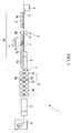
- FIG. 1 is a view showing the schematic structure and functional structure of a conveying device 20 according to an embodiment of the invention and a hot rolling apparatus 1 including the conveying device 20.
- the hot rolling apparatus 1 includes a heating furnace 2, a front table 3, a roughing mill 4, a rear table 5, a heat-retaining/heating furnace 6, a shearing machine 7, a finishing mill 8, a cooling device 9, a winding machine 10, a control unit 11, and an impact prediction data collecting unit 12.
- the heating furnace 2 heats a slab X (workpiece), which contains steel as a main ingredient and copper, up to a temperature suitable for rough rolling before the slab is rolled by the roughing mill 4.
- the front table 3 is disposed at the subsequent stage of the heating furnace 2, and includes a plurality of conveying rollers 3a that is arranged in a line direction.
- the front table 3 conveys the slab X, which is carried out of the heating furnace 2, to the roughing mill 4 and supports the slab X from below when the slab X is repeatedly rolled while being moved back and forth in the roughing mill 4 which is described below.
- the roughing mill 4 includes a pair of rolling rollers 41 and 42 to be rotated, and shapes the slab X into a metal sheet Y (workpiece) by rolling the slab X between the rolling rollers 41 and 42.
- the rolling rollers 41 and 42 are rotationally driven in synchronization with each other, but the rotation directions of the rolling rollers may be reversed. For this reason, it is possible to repeatedly roll the slab while moving back and forth the slab X.
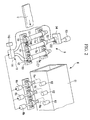
- FIG. 2 is a perspective view of the heat-retaining/heating furnace 6 and the rear table 5.
- the rear table 5 includes a plurality of conveying rollers 5a arranged in a line direction, axle boxes 50 and 51, a drive shaft 52, a motor 53, and a gearbox 54.
- the rear table 5 conveys the metal sheet Y, which is carried out of the roughing mill 4, to the heat-retaining/heating furnace 6 and supports the slab X from below when the slab X is repeatedly rolled while being moved back and forth in the roughing mill 4.
- the conveying rollers 5a are rotatably supported by the axle boxes 50 and 51.
- the drive shaft 52 is connected to the conveying roller 5a, and a driving force of the motor 53 is transmitted to the drive shaft 52 through gears that are received in the gearbox 54.
- the length of the rear table 5 is set to be larger than the length of the slab X that protrudes from the roughing mill 4 in the final back and forth movement of the slab X from the roughing mill 4 toward the heat-retaining/heating furnace 6.
- the final back and forth movement which has been described here, means the back and forth movement (pass before the final pass) of the slab before the slab X is finally moved from the roughing mill 4 to the finishing mill 8. That is, the length of the slab X, which protrudes from the roughing mill 4 in the final back and forth movement, is the length of the slab X, which protrudes from the roughing mill 4 before the slab X is finally moved from the roughing mill 4 to the finishing mill 8 (in the pass before the final pass).
- the length of the rear table 5 is set to be larger than the length of the slab X when the slab X protrudes most from the roughing mill 4 toward the heat-retaining/heating furnace 6. For this reason, the front end of the slab X does not reach the heat-retaining/heating furnace 6 in the rolling of the slab X that is performed at the roughing mill 4, and the slab X is not exposed to an atmosphere in the heat-retaining/heating furnace 6 during the period of the rolling of the slab X that is performed at the roughing mill 4.
- the heat-retaining/heating furnace 6 includes a tunnel furnace 61 and heating burners 62.
- the heat-retaining/heating furnace 6 retains the heat of the metal sheet Y and heats the metal sheet independently of the heating furnace 2, and keeps the metal sheet Y at a temperature of about 1100°C in the hot rolling apparatus 1.
- the heat-retaining/heating furnace 6 has a length (for example, 60 to 70 m) close to the entire length of the metal sheet Y that is carried out of the roughing mill 4.
- the heat-retaining/heating furnace 6 may retain the heat of the metal sheet Y without bending the metal sheet.
- a plurality of conveying rollers 6a (rollers in the furnace) is arranged inside the heat-retaining/heating furnace 6 in the line direction, and the metal sheet Y is movably supported by these conveying rollers 6a.
- the conveying rollers 6a are rotationally driven by the driving forces of drive motors 6b. Further, when the wave or warpage of the metal sheet Y is small, the conveying speed of the metal sheet Y in the heat-retaining/heating furnace 6 of the hot rolling apparatus 1 is about 300 m/minute. When the wave or warpage of the metal sheet Y is large, the conveying speed of the metal sheet in the heat-retaining/heating furnace 6 is lowest, that is, about 100 m/minute.
- the conveying roller 6a is made of heat-resistant steel that has a predetermined strength even at a temperature of 1100°C.
- the conveying device 20 of the hot rolling apparatus 1 includes a front table 3, the rear table 5, the conveying rollers 6a, and the drive motors 6b.
- the shearing machine 7 is provided at the subsequent stage of the heat-retaining/heating furnace 6, and cuts the front end of the metal sheet Y that is carried out of the heat-retaining/heating furnace 6.
- the finishing mill 8 includes a plurality of rolling mills 81 that is formed of a plurality of rolling rollers 8a and is arranged along the line. The finishing mill 8 sets the shape of the metal sheet Y by further rolling the metal sheet Y that is carried out of the heat-retaining/heating furnace 6.
- the cooling device 9 is provided at the subsequent stage of the finishing mill 8, and cools the metal sheet Y of which the shape is set by the finishing mill 8. In this embodiment, the cooling device 9 cools the metal sheet Y by water cooling.
- the winding machine 10 is provided at the subsequent stage of the cooling device 9, and winds the metal sheet Y that is cooled by the cooling device 9.
- the control unit 11 controls the entire operation of the hot rolling apparatus 1, and is electrically connected to the heating furnace 2, the front table 3, the roughing mill 4, the rear table 5, the heat-retaining/heating furnace 6, the shearing machine 7, the finishing mill 8, the cooling device 9, the winding machine 10, and the impact prediction data collecting unit 12.
- the control unit 11 includes a data processor 111 and a data storage unit 112.
- the data processor 111 determines the rotational speed of the conveying rollers 6a by the data input from the impact prediction data collecting unit 12, and controls the drive motors 6b.
- the data storage unit 112 stores the data that are input from the impact prediction data collecting unit 12 through the data processor 111.
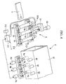
- FIG. 3A shows a front view of the axle box 50 (bearing unit) and FIG. 3B shows a side view of the axle box 50.
- the impact prediction data collecting unit 12 includes the axle box 50, a plate detecting HMD (Hot Metal Detector) 121, and a speed detector 122.
- HMD Hot Metal Detector
- the axle box 50 includes an annular portion 501 and a pedestal portion 502.
- the annular portion 501 is an annular portion that holds the end portion of the conveying roller 5a.
- the pedestal portion 502 extends from a lower portion of the annular portion 501 in a width direction of a shaft, has a substantially trapezoidal shape, and supports the annular portion 501. Since a recess 502a is formed on the lower surface of the pedestal portion 502, the thickness of the pedestal portion is relatively thin.
- a middle portion of the recess 502a is formed substantially along the curvature of the annular portion 501.
- the pedestal portion 502 includes detachable support bolts 502b, which are used to reinforce the thin pedestal portion 502 as necessary, on both sides of the recess 502a.
- the pedestal portion 502 is provided with a strain gauge 502c that is attached to the middle position of the recess 502a, and an accelerometer 502d that is disposed in the recess 502a at a position not overlapping the strain gauge 502c.
- the strain gauge 502c outputs a signal, which corresponds to the strain generated at the middle position of the recess 502a, to the data processor 111.
- the accelerometer 502d outputs a measured value to the data processor 111.
- the plate detecting HMD 121 is provided on the upstream side of the axle box 50. When detecting the metal sheet Y, the plate detecting HMD 121 outputs a signal, which represents that the metal sheet Y approaches the axle box 50, to the data processor 111.
- the speed detector 122 is mounted on the gearbox 54. The speed detector 122 detects the rotational speed of the drive shaft and outputs the rotational speed to the data processor 111.
- the data processor 111 calculates the conveying speed of the metal sheet Y on the basis of the rotational speed of the drive shaft that is input from the speed detector 122.
- the heated slab X is supplied to the roughing mill 4.
- the slab X which is supplied to the roughing mill 4, is repeatedly rolled by the roughing mill 4 while being moved back and forth several times (for example, three times).
- the slab X is shaped into a metal sheet Y.
- the slab X is supported from below by the front table 3 or the rear table 5 and is movable to the left and right sides of the conveying direction of the slab X.
- the metal sheet Y which is shaped by the roughing mill 4, is supplied to the heat-retaining/heating furnace 6 through the rear table 5 at a speed of 100 to 300 m/minute and is kept at a temperature of about 1100°C.
- the metal sheet is further rolled by the finishing mill 8.
- the metal sheet has a desired thickness. Further, after being cooled by the cooling device 9, the metal sheet Y rolled by the finishing mill 8 is wound by the winding machine 10.
- the conveying speed of the metal sheet Y in the heat-retaining/heating furnace 6 is controlled by the control unit 11. A procedure thereof will be described below in detail.
- the control unit 11 predicts the magnitude of an impact, which is applied to the conveying rollers 5a by the metal sheet Y conveyed on the rear table 5, on the basis of the data collected by the impact prediction data collecting unit 12. Specifically, if the plate detecting HMD 121 detects the metal sheet Y and outputs a signal to the data processor 111, the data processor 111 calculates the strain, which is generated at the pedestal portion 502, by a signal input from the strain gauge 502c and calculates vibration, which is generated at the pedestal portion 502, by a signal input from the accelerometer 502d.
- the data processor 111 calculates the magnitude of an impact, which is applied to the conveying rollers 5a by the metal sheet Y, from the strain and vibration, and regards the calculated value as a predictive value of the magnitude of an impact that is applied to the conveying roller 6a by the metal sheet Y.
- the data processor 111 determines an appropriate value of the conveying speed of the metal sheet Y in the heat-retaining/heating furnace 6, on the basis of the predictive value. Moreover, the data processor 111 adjusts the conveying speed of the metal sheet Y in the heat-retaining/heating furnace 6 by controlling the drive motors 6b, and controls the motor 53 so that the conveying speed calculated from the rotational speed input from the speed detector 122 is close to the appropriate value.
- the temperature in the heat-retaining/heating furnace 6 is set to 1100°C that is higher than the temperature in the conventional heat-retaining/heating furnace and the conveying speed of the metal sheet Y is set to 300 m/minute that is about three times as high as the conventional speed of the metal sheet, it is possible to reduce an impact, which is applied to the conveying rollers 6a, by reducing the conveying speed of the metal sheet Y if the magnitude of an impact, which is applied to the conveying rollers 6a by the metal sheet Y, exceeds a value of an impact that can be withstood by the conveying rollers 6a kept (or heated) at a temperature of 1100°C.
- the magnitude of an impact, which is applied to the conveying roller 6a by the metal sheet Y on the upstream of the heat-retaining/heating furnace 6, is predicted and the conveying speed of the metal sheet Y in the heat-retaining/heating furnace 6 is adjusted according to the predicted magnitude of the impact. Accordingly, it is possible to increase the conveying speed if a small impact is predicted, and to reduce the conveying speed if a large impact is predicted.
- FIG. 4 is a perspective view showing an impact prediction data collecting unit 212 of the modification.
- the impact prediction data collecting unit 212 of this modification includes an imaging device 212a instead of the axle box 50 and the plate detecting HMD 121 of the impact prediction data collecting unit 12 of the embodiment. Further, the impact prediction data collecting unit 212 includes the same speed detector 122 as the speed detector 122 of the impact prediction data collecting unit 12 of the embodiment, in addition to the imaging device 212a. Further, the difference between this modification and the embodiment has been as described above, and other portions of the modification are the same as those of the embodiment.
- the imaging device 212a takes an image above the rear table 5, and outputs the photographed image to the data processor 111.
- the data processor 111 analyzes the states of the wave, warpage, and vibration of the metal sheet Y on the basis of the image input from the imaging device 212a, and determines an appropriate value of the conveying speed of the metal sheet Y in the heat-retaining/heating furnace 6, on the basis of the results of analysis. According to this structure, it is possible to obtain the same effects as the embodiment.
- the invention it is possible to prevent the breakage of the roller in the furnace even though the temperature and speed of the hot rolling are increased as a whole, by increasing the processing temperature and appropriately increasing the conveying speed between, particularly, rough rolling and finish rolling of hot rolling.
Landscapes
- Engineering & Computer Science (AREA)
- Mechanical Engineering (AREA)
- General Engineering & Computer Science (AREA)
- Metal Rolling (AREA)
Abstract
Description
- The present invention relates to a conveying device, a hot rolling apparatus, a conveying method, and a hot rolling method.
Priority is claimed on Japanese Patent Application No.2008-008136, filed on January 17, 2008 - In the past, a hot rolling apparatus, which performs the hot rolling of a workpiece such as a steel plate, has included a roughing mill and a finishing mill, and has further included a heating furnace or a heat-retaining/heating furnace, a shearing machine, a winding machine, and the like.
The above-mentioned hot rolling apparatus, first, heats a workpiece by a heating furnace. Then, the hot rolling apparatus performs the rough rolling of the workpiece by a roughing mill, conveys the workpiece while reheating the workpiece and retaining the heat of the workpiece by the heat-retaining/heating furnace, cuts front and rear ends of the workpiece by a shearing machine, performs the finish rolling of the workpiece by a finishing mill, and winds the workpiece using a winding machine. - Meanwhile, the conveying roller in the heat-retaining/heating furnace is made of heat-resistant steel so as to withstand high temperatures.
However, since deformation, such as wave or warpage, occurs at (particularly, a front end portion of) the workpiece that has been subject to the rough rolling, the conveying rollers in the heat-retaining/heating furnace receive an impact from the workpiece. For this reason, the internal temperature of the heat-retaining/heating furnace is set so that the strength of the conveying roller does not deteriorate. Further, the conveying speed of the workpiece in the heat-retaining/heating furnace is set so that an impact exceeding an impact capable of being withstood by the conveying roller is not applied to the conveying roller. Specifically, the internal temperature is set to 1000°C or less and the conveying speed is set to about 100 m/minute.
[Patent Citation 1] Japanese Unexamined Patent Application, First Publication No.H07-88528 - Conventionally, the internal temperature of the heat-retaining/heating furnace and the conveying speed have been limited due to the above-mentioned circumstances, so that the internal temperature of the heat-retaining/heating furnace and the conveying speed could not be increased. However, in terms of metallurgy, it is preferable that the internal temperature of the heat-retaining/heating furnace be increased as compared to the current set temperature. Further, in terms of work efficiency, it is preferable that the conveying speed be increased.
However, if the conveying speed in the heat-retaining/heating furnace is increased, there occurs a problem that an impact applied to the conveying roller from a deformed portion of the workpiece is increased. Moreover, if the internal temperature of the heat-retaining/heating furnace is set to a high temperature, there occurs a problem that the strength of the conveying roller decreases. - The invention has been made in consideration of the above-mentioned circumstances, and an object of the invention is to provide a conveying device, a hot rolling apparatus, a conveying method, and a hot rolling method that can prevent the breakage of a conveying roller even though the temperature and speed of hot rolling are increased.
- In order to solve the above-mentioned problems, a conveying device, a hot rolling apparatus, a conveying method, and a hot rolling method according to the invention have employed the following means.
According to a first aspect of the invention, there is provided a conveying device that includes a plurality of conveying rollers supported in parallel at predetermined intervals and conveys a workpiece to a heat-retaining/heating furnace from a rolling mill by the conveying rollers. The conveying device includes an impact prediction data collecting unit and a control unit. The impact prediction data collecting unit acquires data on the upstream of the heat-retaining/heating furnace. The data is used to predict the magnitude of an impact applied to rollers in the furnace, which are positioned in the heat-retaining/heating furnace, of the conveying rollers by the workpiece. The control unit predicts the magnitude of an impact from the data, which is acquired by the impact prediction data collecting unit, and adjusts the conveying speed of the workpiece in the heat-retaining/heating furnace according to the magnitude of the impact. - Then, in the aspect of the invention, the impact prediction data collecting unit is provided at a bearing unit that supports at least one of the conveying rollers, and acquires data, which relates to at least one of deformation and vibration of the bearing unit, as the data.
- Further, in the aspect of the invention, the impact prediction data collecting unit includes an imaging device, and acquires an image of the workpiece conveyed on the upstream of the heat-retaining/heating furnace, which is photographed by the imaging device, as the data.
- Furthermore, in the aspect of the invention, the heat-retaining/heating furnace heats and keeps the workpiece at a temperature of 1000°C or more.
- Moreover, in the aspect of the invention, the maximum conveying speed of the workpiece, which is conveyed by the rollers in the furnace, is 200 m/minute or more.
- According to a second aspect of the invention, there is provided a hot rolling apparatus for rolling a workpiece, which is heated by a heating furnace, by a roughing mill, conveying the workpiece to a finishing mill while adjusting the temperature of the workpiece by a heat-retaining/heating furnace, and rolling the workpiece by the finishing mill. The hot rolling apparatus includes the conveying device according to the first aspect of the invention.
- According to a third aspect of the invention, there is provided a conveying method of conveying a workpiece to a heat-retaining/heating furnace from a rolling mill by moving the workpiece on a plurality of conveying rollers that is supported in parallel at predetermined intervals. The conveying method includes predicting the magnitude of an impact that is applied to rollers in the furnace by the workpiece on the upstream of the heat-retaining/heating furnace, and adjusting a conveying speed of the workpiece in the heat-retaining/heating furnace according to the magnitude of the predicted impact. The rollers in the furnace are the conveying rollers positioned in the heat-retaining/heating furnace.
- Then, in the aspect of the invention, the prediction of the impact is performed on the basis of at least one of deformation and vibration of a bearing unit that supports at least one of the conveying rollers.
- Further, in the aspect of the invention, the prediction of the impact is performed on the basis of a photographed image of the workpiece that is conveyed on the upstream of the heat-retaining/heating furnace.
- Furthermore, in the aspect of the invention, the heat-retaining/heating furnace heats and keeps the workpiece at a temperature of 1000°C or more.
- Moreover, in the aspect of the invention, the maximum conveying speed of the workpiece, which is conveyed by the rollers in the furnace, is 200 m/minute or more.
- According to a fourth aspect of the invention, there is provided a hot rolling method of hot rolling a workpiece. The hot rolling method includes conveying the workpiece by the conveying method according to the third aspect.
- According to the invention, the magnitude of an impact, which is applied to the roller in the furnace by the workpiece, is predicted on the upstream of the heat-retaining/heating furnace and the conveying speed of the workpiece in the heat-retaining/heating furnace is adjusted according to the predicted magnitude of the impact. Accordingly, it is possible to increase the conveying speed if a small impact is predicted, and to reduce the conveying speed if a large impact is predicted.
Accordingly, even if the strength of the roller in the furnace is decreased as compared to the strength of the roller in the furnace at conventional set temperature due to the increase of the internal temperature of the heat-retaining/heating furnace, it is possible to appropriately increase the conveying speed by grasping the magnitude of the impact, which can be withstood by the roller in the furnace, and adjusting the conveying speed so that an impact larger than the impact is not applied to the roller in the furnace.
Therefore, it is possible to prevent the breakage of the roller in the furnace even though the temperature and speed of the hot rolling are increased as a whole, by increasing the processing temperature and appropriately increasing the conveying speed during the time, particularly, after rough rolling and before finishing rolling of hot rolling. -
-
FIG. 1 is a view showing the schematic structure and functional structure of a conveying device according to an embodiment of the invention and a hot rolling apparatus including the conveying device -
FIG. 2 is a perspective view of a heat-retaining/heating furnace and a rear table of the embodiment. -
FIG. 3A shows a front view of an axle box of the embodiment. -
FIG. 3B shows a side view of an axle box of the embodiment. -
FIG. 4 is a perspective view showing an impact prediction data collecting unit of a modification of the embodiment. -
- 1
- HOT ROLLING APPARATUS
- 2
- HEATING FURNACE
- 3
- FRONT TABLE
- 3a
- CONVEYING ROLLER
- 4
- ROUGHING MILL
- 5
- REAR TABLE
- 5a
- CONVEYING ROLLER
- 50
- AXLE BOX (BEARING UNIT)
- 6
- HEAT-RETAINING/HEATING FURNACE
- 6a
- CONVEYING ROLLER (ROLLER IN A FURNACE)
- 6b
- DRIVE MOTOR
- 11
- CONTROL UNIT
- 12
- IMPACT PREDICTION DATA COLLECTING UNIT
- 20
- CONVEYING DEVICE
- X
- SLAB (WORKPIECE)
- Y
- METAL SHEET (WORKPIECE)
- 212
- IMPACT PREDICTION DATA COLLECTING UNIT
- 212a
- IMAGING DEVICE
- An embodiment of the invention will be described below with reference to drawings.
FIG. 1 is a view showing the schematic structure and functional structure of a conveyingdevice 20 according to an embodiment of the invention and a hot rolling apparatus 1 including the conveyingdevice 20.
As shown in this drawing, the hot rolling apparatus 1 according to this embodiment includes aheating furnace 2, a front table 3, aroughing mill 4, a rear table 5, a heat-retaining/heating furnace 6, a shearing machine 7, a finishingmill 8, acooling device 9, a windingmachine 10, acontrol unit 11, and an impact predictiondata collecting unit 12. - The
heating furnace 2 heats a slab X (workpiece), which contains steel as a main ingredient and copper, up to a temperature suitable for rough rolling before the slab is rolled by theroughing mill 4. - The front table 3 is disposed at the subsequent stage of the
heating furnace 2, and includes a plurality of conveyingrollers 3a that is arranged in a line direction.
The front table 3 conveys the slab X, which is carried out of theheating furnace 2, to theroughing mill 4 and supports the slab X from below when the slab X is repeatedly rolled while being moved back and forth in theroughing mill 4 which is described below. - The
roughing mill 4 includes a pair of rollingrollers rollers rollers - Here, the embodiment of the invention will continue to be described with reference to
FIG. 2 in addition toFIG. 1 .FIG. 2 is a perspective view of the heat-retaining/heating furnace 6 and the rear table 5.
The rear table 5 includes a plurality of conveyingrollers 5a arranged in a line direction,axle boxes drive shaft 52, amotor 53, and agearbox 54. The rear table 5 conveys the metal sheet Y, which is carried out of theroughing mill 4, to the heat-retaining/heating furnace 6 and supports the slab X from below when the slab X is repeatedly rolled while being moved back and forth in theroughing mill 4. - The conveying
rollers 5a are rotatably supported by theaxle boxes drive shaft 52 is connected to the conveyingroller 5a, and a driving force of themotor 53 is transmitted to thedrive shaft 52 through gears that are received in thegearbox 54. - The length of the rear table 5 is set to be larger than the length of the slab X that protrudes from the
roughing mill 4 in the final back and forth movement of the slab X from theroughing mill 4 toward the heat-retaining/heating furnace 6.
Meanwhile, the final back and forth movement, which has been described here, means the back and forth movement (pass before the final pass) of the slab before the slab X is finally moved from theroughing mill 4 to thefinishing mill 8. That is, the length of the slab X, which protrudes from theroughing mill 4 in the final back and forth movement, is the length of the slab X, which protrudes from theroughing mill 4 before the slab X is finally moved from theroughing mill 4 to the finishing mill 8 (in the pass before the final pass). - That is, in the hot rolling apparatus 1, in the case of the final back and forth movement, the length of the rear table 5 is set to be larger than the length of the slab X when the slab X protrudes most from the
roughing mill 4 toward the heat-retaining/heating furnace 6.
For this reason, the front end of the slab X does not reach the heat-retaining/heating furnace 6 in the rolling of the slab X that is performed at theroughing mill 4, and the slab X is not exposed to an atmosphere in the heat-retaining/heating furnace 6 during the period of the rolling of the slab X that is performed at theroughing mill 4. - The heat-retaining/
heating furnace 6 includes atunnel furnace 61 andheating burners 62. The heat-retaining/heating furnace 6 retains the heat of the metal sheet Y and heats the metal sheet independently of theheating furnace 2, and keeps the metal sheet Y at a temperature of about 1100°C in the hot rolling apparatus 1.
The heat-retaining/heating furnace 6 has a length (for example, 60 to 70 m) close to the entire length of the metal sheet Y that is carried out of theroughing mill 4. The heat-retaining/heating furnace 6 may retain the heat of the metal sheet Y without bending the metal sheet. - Meanwhile, a plurality of conveying
rollers 6a (rollers in the furnace) is arranged inside the heat-retaining/heating furnace 6 in the line direction, and the metal sheet Y is movably supported by these conveyingrollers 6a.
The conveyingrollers 6a are rotationally driven by the driving forces ofdrive motors 6b. Further, when the wave or warpage of the metal sheet Y is small, the conveying speed of the metal sheet Y in the heat-retaining/heating furnace 6 of the hot rolling apparatus 1 is about 300 m/minute. When the wave or warpage of the metal sheet Y is large, the conveying speed of the metal sheet in the heat-retaining/heating furnace 6 is lowest, that is, about 100 m/minute.
The conveyingroller 6a is made of heat-resistant steel that has a predetermined strength even at a temperature of 1100°C. - Further, the conveying
device 20 of the hot rolling apparatus 1 includes a front table 3, the rear table 5, the conveyingrollers 6a, and thedrive motors 6b. - Returning to
FIG. 1 , the shearing machine 7 is provided at the subsequent stage of the heat-retaining/heating furnace 6, and cuts the front end of the metal sheet Y that is carried out of the heat-retaining/heating furnace 6.
The finishingmill 8 includes a plurality of rollingmills 81 that is formed of a plurality of rollingrollers 8a and is arranged along the line. The finishingmill 8 sets the shape of the metal sheet Y by further rolling the metal sheet Y that is carried out of the heat-retaining/heating furnace 6. - The
cooling device 9 is provided at the subsequent stage of the finishingmill 8, and cools the metal sheet Y of which the shape is set by the finishingmill 8. In this embodiment, thecooling device 9 cools the metal sheet Y by water cooling.
The windingmachine 10 is provided at the subsequent stage of thecooling device 9, and winds the metal sheet Y that is cooled by thecooling device 9. - The
control unit 11 controls the entire operation of the hot rolling apparatus 1, and is electrically connected to theheating furnace 2, the front table 3, theroughing mill 4, the rear table 5, the heat-retaining/heating furnace 6, the shearing machine 7, the finishingmill 8, thecooling device 9, the windingmachine 10, and the impact predictiondata collecting unit 12. - As shown in
FIG. 2 , thecontrol unit 11 includes adata processor 111 and adata storage unit 112.
Thedata processor 111 determines the rotational speed of the conveyingrollers 6a by the data input from the impact predictiondata collecting unit 12, and controls thedrive motors 6b. Thedata storage unit 112 stores the data that are input from the impact predictiondata collecting unit 12 through thedata processor 111. - The impact prediction
data collecting unit 12 will be described below with reference toFIGS. 3A and 3B. FIG. 3A shows a front view of the axle box 50 (bearing unit) andFIG. 3B shows a side view of theaxle box 50.
As shown inFIG. 2 , the impact predictiondata collecting unit 12 includes theaxle box 50, a plate detecting HMD (Hot Metal Detector) 121, and aspeed detector 122. - The
axle box 50 includes anannular portion 501 and apedestal portion 502.
Theannular portion 501 is an annular portion that holds the end portion of the conveyingroller 5a.
Thepedestal portion 502 extends from a lower portion of theannular portion 501 in a width direction of a shaft, has a substantially trapezoidal shape, and supports theannular portion 501. Since arecess 502a is formed on the lower surface of thepedestal portion 502, the thickness of the pedestal portion is relatively thin. - A middle portion of the
recess 502a is formed substantially along the curvature of theannular portion 501. Further, thepedestal portion 502 includesdetachable support bolts 502b, which are used to reinforce thethin pedestal portion 502 as necessary, on both sides of therecess 502a.
Further, thepedestal portion 502 is provided with astrain gauge 502c that is attached to the middle position of therecess 502a, and anaccelerometer 502d that is disposed in therecess 502a at a position not overlapping thestrain gauge 502c.
Thestrain gauge 502c outputs a signal, which corresponds to the strain generated at the middle position of therecess 502a, to thedata processor 111. Theaccelerometer 502d outputs a measured value to thedata processor 111. - The
plate detecting HMD 121 is provided on the upstream side of theaxle box 50. When detecting the metal sheet Y, theplate detecting HMD 121 outputs a signal, which represents that the metal sheet Y approaches theaxle box 50, to thedata processor 111.
Thespeed detector 122 is mounted on thegearbox 54. Thespeed detector 122 detects the rotational speed of the drive shaft and outputs the rotational speed to thedata processor 111. Thedata processor 111 calculates the conveying speed of the metal sheet Y on the basis of the rotational speed of the drive shaft that is input from thespeed detector 122. - The operation of the hot rolling apparatus 1 according to this embodiment, which has the above-mentioned structure, will be described below. Meanwhile, the operation of the hot rolling apparatus 1 is mainly performed by the above-mentioned
control unit 11. - First, if a slab X is heated up to a predetermined temperature in the
heating furnace 2, the heated slab X is supplied to theroughing mill 4.
The slab X, which is supplied to theroughing mill 4, is repeatedly rolled by theroughing mill 4 while being moved back and forth several times (for example, three times). As a result, the slab X is shaped into a metal sheet Y.
Here, while the slab X is rolled by theroughing mill 4 of the hot rolling apparatus 1, the slab X is supported from below by the front table 3 or the rear table 5 and is movable to the left and right sides of the conveying direction of the slab X. - The metal sheet Y, which is shaped by the
roughing mill 4, is supplied to the heat-retaining/heating furnace 6 through the rear table 5 at a speed of 100 to 300 m/minute and is kept at a temperature of about 1100°C.
After the front end portion of the metal sheet Y carried out of the heat-retaining/heating furnace 6 is cut by the shearing machine 7, the metal sheet is further rolled by the finishingmill 8. As a result, the metal sheet has a desired thickness.
Further, after being cooled by thecooling device 9, the metal sheet Y rolled by the finishingmill 8 is wound by the windingmachine 10. - The conveying speed of the metal sheet Y in the heat-retaining/
heating furnace 6 is controlled by thecontrol unit 11. A procedure thereof will be described below in detail. - First, the
control unit 11 predicts the magnitude of an impact, which is applied to the conveyingrollers 5a by the metal sheet Y conveyed on the rear table 5, on the basis of the data collected by the impact predictiondata collecting unit 12.
Specifically, if theplate detecting HMD 121 detects the metal sheet Y and outputs a signal to thedata processor 111, thedata processor 111 calculates the strain, which is generated at thepedestal portion 502, by a signal input from thestrain gauge 502c and calculates vibration, which is generated at thepedestal portion 502, by a signal input from theaccelerometer 502d. Further, thedata processor 111 calculates the magnitude of an impact, which is applied to the conveyingrollers 5a by the metal sheet Y, from the strain and vibration, and regards the calculated value as a predictive value of the magnitude of an impact that is applied to the conveyingroller 6a by the metal sheet Y. - After that, the
data processor 111 determines an appropriate value of the conveying speed of the metal sheet Y in the heat-retaining/heating furnace 6, on the basis of the predictive value.
Moreover, thedata processor 111 adjusts the conveying speed of the metal sheet Y in the heat-retaining/heating furnace 6 by controlling thedrive motors 6b, and controls themotor 53 so that the conveying speed calculated from the rotational speed input from thespeed detector 122 is close to the appropriate value. - According to the above-mentioned embodiment, even though the temperature in the heat-retaining/
heating furnace 6 is set to 1100°C that is higher than the temperature in the conventional heat-retaining/heating furnace and the conveying speed of the metal sheet Y is set to 300 m/minute that is about three times as high as the conventional speed of the metal sheet, it is possible to reduce an impact, which is applied to the conveyingrollers 6a, by reducing the conveying speed of the metal sheet Y if the magnitude of an impact, which is applied to the conveyingrollers 6a by the metal sheet Y, exceeds a value of an impact that can be withstood by the conveyingrollers 6a kept (or heated) at a temperature of 1100°C. - That is, the magnitude of an impact, which is applied to the conveying
roller 6a by the metal sheet Y on the upstream of the heat-retaining/heating furnace 6, is predicted and the conveying speed of the metal sheet Y in the heat-retaining/heating furnace 6 is adjusted according to the predicted magnitude of the impact. Accordingly, it is possible to increase the conveying speed if a small impact is predicted, and to reduce the conveying speed if a large impact is predicted.
Accordingly, even if the strength of the conveyingroller 6a is decreased as compared to the strength of the conveyingroller 6a at conventional set temperature due to the increase of the internal temperature of the heat-retaining/heating furnace 6, it is possible to appropriately increase the conveying speed by grasping the magnitude of the impact, which can be withstood by the conveyingroller 6a, and adjusting the conveying speed so that an impact larger than the impact is not applied to the conveyingrollers 6a.
Therefore, it is possible to prevent the breakage of the roller in the furnace even though the temperature and speed of the hot rolling are increased as a whole, by increasing the processing temperature and appropriately increasing the conveying speed between, particularly, rough rolling and finish rolling of hot rolling. - The hot rolling apparatus according to the preferred embodiment of the invention has been described above with reference to the drawings, but it goes without saying that the invention is not limited to the above-mentioned embodiment. The shapes and combination of the respective components described in the above-mentioned embodiment are illustrative, and may be modified in various ways on the basis of design requests and the like without departing from the scope of the invention.
- The following shown in
FIG. 4 is considered as a modification of the embodiment.FIG. 4 is a perspective view showing an impact predictiondata collecting unit 212 of the modification.
The impact predictiondata collecting unit 212 of this modification includes animaging device 212a instead of theaxle box 50 and theplate detecting HMD 121 of the impact predictiondata collecting unit 12 of the embodiment. Further, the impact predictiondata collecting unit 212 includes thesame speed detector 122 as thespeed detector 122 of the impact predictiondata collecting unit 12 of the embodiment, in addition to theimaging device 212a.
Further, the difference between this modification and the embodiment has been as described above, and other portions of the modification are the same as those of the embodiment. - The
imaging device 212a takes an image above the rear table 5, and outputs the photographed image to thedata processor 111.
Thedata processor 111 analyzes the states of the wave, warpage, and vibration of the metal sheet Y on the basis of the image input from theimaging device 212a, and determines an appropriate value of the conveying speed of the metal sheet Y in the heat-retaining/heating furnace 6, on the basis of the results of analysis.
According to this structure, it is possible to obtain the same effects as the embodiment. - According to the invention, it is possible to prevent the breakage of the roller in the furnace even though the temperature and speed of the hot rolling are increased as a whole, by increasing the processing temperature and appropriately increasing the conveying speed between, particularly, rough rolling and finish rolling of hot rolling.
Claims (12)
- A conveying device that includes a plurality of conveying rollers supported in parallel at predetermined intervals, and conveys a workpiece to a heat-retaining/heating furnace from a rolling mill by the conveying rollers, the conveying device comprising:an impact prediction data collecting unit that acquires data on the upstream of the heat-retaining/heating furnace, the data being used to predict the magnitude of an impact applied to rollers in the furnace, which are positioned in the heat-retaining/heating furnace, of the conveying rollers by the workpiece; anda control unit that predicts the magnitude of an impact from the data, which is acquired by the impact prediction data collecting unit, and adjusts the conveying speed of the workpiece in the heat-retaining/heating furnace according to the magnitude of the impact.
- The conveying device according to claim 1,
wherein the impact prediction data collecting unit is provided at a bearing unit that supports at least one of the conveying rollers, and acquires data, which relates to at least one of deformation and vibration of the bearing unit, as the data. - The conveying device according to claim 1,
wherein the impact prediction data collecting unit includes an imaging device, and acquires an image of the workpiece conveyed on the upstream of the heat-retaining/heating furnace, which is photographed by the imaging device, as the data. - The conveying device according to any one of claims 1 to 3,
wherein the heat-retaining/heating furnace heats and keeps the workpiece at a temperature of 1000°C or more. - The conveying device according to claim 1,
wherein the maximum conveying speed of the workpiece, which is conveyed by the rollers in the furnace, is 200 m/minute or more. - A hot rolling apparatus for rolling a workpiece, which is heated by a heating furnace, by a roughing mill, conveying the workpiece to a finishing mill while adjusting the temperature of the workpiece by a heat-retaining/heating furnace, and rolling the workpiece by the finishing mill, the hot rolling apparatus comprising:the conveying device according to claim 1.
- A conveying method of conveying a workpiece to a heat-retaining/heating furnace from a rolling mill by moving the workpiece on a plurality of conveying rollers that is supported in parallel at predetermined intervals, the conveying method comprising:predicting the magnitude of an impact that is applied to rollers in the furnace by the workpiece, the rollers in the furnace being the conveying rollers positioned in the heat-retaining/heating furnace on the upstream of the heat-retaining/heating furnace; andadjusting a conveying speed of the workpiece in the heat-retaining/heating furnace according to the magnitude of the predicted impact.
- The conveying method according to claim 7,
wherein the prediction of the impact is performed on the basis of at least one of deformation and vibration of a bearing unit that supports at least one of the conveying rollers. - The conveying method according to claim 7,
wherein the prediction of the impact is performed on the basis of a photographed image of the workpiece that is conveyed on the upstream of the heat-retaining/heating furnace. - The conveying method according to claim 7,
wherein the heat-retaining/heating furnace heats and keeps the workpiece at a temperature of 1000°C or more. - The conveying method according to claim 7,
wherein the maximum conveying speed of the workpiece, which is conveyed by the rollers in the furnace, is 200 m/minute or more. - A hot rolling method of hot rolling a workpiece, the hot rolling method comprising:conveying the workpiece by the conveying method according to claim 7.
Applications Claiming Priority (2)
| Application Number | Priority Date | Filing Date | Title |
|---|---|---|---|
| JP2008008136A JP5134979B6 (en) | 2008-01-17 | Conveying apparatus, hot rolling apparatus, conveying method and hot rolling method | |
| PCT/JP2009/050462 WO2009090993A1 (en) | 2008-01-17 | 2009-01-15 | Carrying apparatus and hot-rolling apparatus, and carrying method and hot-rolling method |
Publications (3)
| Publication Number | Publication Date |
|---|---|
| EP2246130A1 true EP2246130A1 (en) | 2010-11-03 |
| EP2246130A4 EP2246130A4 (en) | 2014-10-29 |
| EP2246130B1 EP2246130B1 (en) | 2015-12-16 |
Family
ID=40885379
Family Applications (1)
| Application Number | Title | Priority Date | Filing Date |
|---|---|---|---|
| EP09701772.7A Not-in-force EP2246130B1 (en) | 2008-01-17 | 2009-01-15 | Carrying apparatus and hot-rolling apparatus, and carrying method and hot-rolling method |
Country Status (5)
| Country | Link |
|---|---|
| US (1) | US8402802B2 (en) |
| EP (1) | EP2246130B1 (en) |
| CN (1) | CN101939119B (en) |
| BR (1) | BRPI0907164A2 (en) |
| WO (1) | WO2009090993A1 (en) |
Cited By (2)
| Publication number | Priority date | Publication date | Assignee | Title |
|---|---|---|---|---|
| CN102527865A (en) * | 2011-12-20 | 2012-07-04 | 中国科学院宁波材料技术与工程研究所 | Forming and conveying device for thermoplastic composite material |
| IT202200018114A1 (en) * | 2022-09-05 | 2024-03-05 | Ema Cer S R L | CONTROLLED MOTORIZATION SYSTEM FOR ROLLER OVENS |
Families Citing this family (10)
| Publication number | Priority date | Publication date | Assignee | Title |
|---|---|---|---|---|
| JP4910071B1 (en) * | 2011-04-28 | 2012-04-04 | 昭男 平根 | Sheet metal repair jig |
| US8662289B2 (en) * | 2012-06-26 | 2014-03-04 | Shenzhen China Star Optoelectronics Technlogy co., Ltd. | Glass substrate transmission device and method for detecting the rotational synchronization of driven shafts |
| CN103331302B (en) * | 2013-07-12 | 2015-07-15 | 山西太钢不锈钢股份有限公司 | Device and method for improving finishing temperature of oriented silicon steel |
| CN107497865A (en) * | 2017-09-22 | 2017-12-22 | 浙江金康铜业有限公司 | Hot-rolled steel plate mechanism |
| CN107838192A (en) * | 2017-11-23 | 2018-03-27 | 鹤山市顺亿达铜业制品有限公司 | A kind of automatic hot-rolling arrangement of copper coin |
| CN110411223B (en) * | 2019-07-10 | 2020-12-29 | 东南大学 | An adjustable furnace roller support device |
| CN113145641B (en) * | 2021-03-19 | 2023-05-23 | 兴化市广福金属制品有限公司 | Stainless steel hot rolling forming device |
| CN113369303B (en) * | 2021-06-09 | 2022-07-19 | 燕山大学 | System and method for automatic vacuum coating and hot rolling of composite plate |
| JP7613347B2 (en) * | 2021-12-15 | 2025-01-15 | トヨタ自動車株式会社 | Apparatus and method for manufacturing positive electrode active material for lithium ion secondary battery |
| CN117735152B (en) * | 2024-02-20 | 2024-05-28 | 泰州市宏华冶金机械有限公司 | Full-automatic roller way conveying line |
Family Cites Families (8)
| Publication number | Priority date | Publication date | Assignee | Title |
|---|---|---|---|---|
| US2056510A (en) * | 1934-01-24 | 1936-10-06 | Fallon John | Conveyer furnace for heating metal sheets or plates |
| JPS6266593A (en) | 1985-09-19 | 1987-03-26 | 川崎製鉄株式会社 | Controlling method for induction heat |
| JP3146786B2 (en) | 1993-09-20 | 2001-03-19 | 株式会社日立製作所 | Hot rolling equipment and hot rolling method |
| DE59504983D1 (en) * | 1995-01-16 | 1999-03-11 | Mannesmann Ag | Device for guiding hot rolled strip through an inductor |
| JP2002019947A (en) | 2000-07-07 | 2002-01-23 | Sumitomo Metal Ind Ltd | How to transport steel |
| JP2004160531A (en) | 2002-11-15 | 2004-06-10 | Nippon Steel Corp | Speed control method for table rolls on front and rear sides of rolling mill |
| CN2734345Y (en) * | 2004-09-29 | 2005-10-19 | 宝山钢铁股份有限公司 | Device for inhibiting band steel jitter employing eletromagnetic technology |
| JP5271512B2 (en) * | 2007-06-18 | 2013-08-21 | Ihiメタルテック株式会社 | Hot rolling equipment |
-
2009
- 2009-01-15 US US12/863,301 patent/US8402802B2/en not_active Expired - Fee Related
- 2009-01-15 EP EP09701772.7A patent/EP2246130B1/en not_active Not-in-force
- 2009-01-15 WO PCT/JP2009/050462 patent/WO2009090993A1/en not_active Ceased
- 2009-01-15 CN CN2009801027719A patent/CN101939119B/en not_active Expired - Fee Related
- 2009-01-15 BR BRPI0907164-4A patent/BRPI0907164A2/en not_active IP Right Cessation
Non-Patent Citations (2)
| Title |
|---|
| No further relevant documents disclosed * |
| See also references of WO2009090993A1 * |
Cited By (2)
| Publication number | Priority date | Publication date | Assignee | Title |
|---|---|---|---|---|
| CN102527865A (en) * | 2011-12-20 | 2012-07-04 | 中国科学院宁波材料技术与工程研究所 | Forming and conveying device for thermoplastic composite material |
| IT202200018114A1 (en) * | 2022-09-05 | 2024-03-05 | Ema Cer S R L | CONTROLLED MOTORIZATION SYSTEM FOR ROLLER OVENS |
Also Published As
| Publication number | Publication date |
|---|---|
| EP2246130A4 (en) | 2014-10-29 |
| US8402802B2 (en) | 2013-03-26 |
| BRPI0907164A2 (en) | 2015-07-07 |
| JP5134979B2 (en) | 2013-01-30 |
| WO2009090993A1 (en) | 2009-07-23 |
| CN101939119B (en) | 2013-05-29 |
| CN101939119A (en) | 2011-01-05 |
| US20100294009A1 (en) | 2010-11-25 |
| EP2246130B1 (en) | 2015-12-16 |
| JP2009166102A (en) | 2009-07-30 |
Similar Documents
| Publication | Publication Date | Title |
|---|---|---|
| EP2246130B1 (en) | Carrying apparatus and hot-rolling apparatus, and carrying method and hot-rolling method | |
| ES2228943T3 (en) | PROCEDURE AND INSTALLATION FOR MANUFACTURE OF RIBBONS AND STEEL SHEETS. | |
| EP2546004B1 (en) | Hot-rolled steel sheet manufacturing method and manufacturing device | |
| KR102018370B1 (en) | Process and apparatus for preparing steel stock before hot rolling | |
| EP2683499B1 (en) | Magnesium roll mill | |
| AU2007264101A1 (en) | A method and a system for producing hot-rolled strip silicon steel based on thin slabs | |
| JP2000507503A (en) | Method and equipment for producing hot rolled steel strip | |
| US8734601B2 (en) | Method for hot rolling a metal slab, strip or sheet | |
| CN1051259C (en) | Method and apparatus for rolling of belt steel from blocks continously casted | |
| RU2011153722A (en) | ENERGY-SAVING ROLLING MACHINE AND ENERGY-SAVING METHOD OF OPERATION OF THE INSTALLATION FOR COMBINED CONTINUOUS CASTING AND ROLLING | |
| CN110573269A (en) | Equipment and processes for multi-modal manufacturing of metal strip and sheet | |
| JP5533376B2 (en) | Magnesium alloy coil material, magnesium alloy grinding device, magnesium alloy coil material grinding method, and magnesium alloy plate | |
| CN101678414B (en) | Hot rolling apparatus | |
| RU2368438C2 (en) | Package unit for receiving of hot-rolled steel strip | |
| JP5134979B6 (en) | Conveying apparatus, hot rolling apparatus, conveying method and hot rolling method | |
| JP2012006070A (en) | Method for production of magnesium alloy coil material | |
| JP5114745B2 (en) | Steel material conveyance control apparatus and method in hot rolling equipment | |
| RU2375129C1 (en) | Method and device for manufacturing of metallic strip by means of direct rolling | |
| JP6065489B2 (en) | Slab conveying equipment and slab conveying method | |
| EP4039381A1 (en) | Method for reducing the thickness of a strip of metal by hot-roll-forming and system for roll-forming a strip of metal by hot-roll-forming | |
| JP2006026808A (en) | Shear cutting control method in continuous hot rolling line | |
| JPH0616898B2 (en) | Plate material winding device | |
| JP2000254706A (en) | Thickness press apparatus and thickness press method for hot material | |
| TH88139A (en) | Methods and Machines for Producing Metal Strips by Extrusion Method | |
| JP2005118843A (en) | Sheet material rolling method |
Legal Events
| Date | Code | Title | Description |
|---|---|---|---|
| PUAI | Public reference made under article 153(3) epc to a published international application that has entered the european phase |
Free format text: ORIGINAL CODE: 0009012 |
|
| 17P | Request for examination filed |
Effective date: 20100816 |
|
| AK | Designated contracting states |
Kind code of ref document: A1 Designated state(s): AT BE BG CH CY CZ DE DK EE ES FI FR GB GR HR HU IE IS IT LI LT LU LV MC MK MT NL NO PL PT RO SE SI SK TR |
|
| AX | Request for extension of the european patent |
Extension state: AL BA RS |
|
| DAX | Request for extension of the european patent (deleted) | ||
| RAP1 | Party data changed (applicant data changed or rights of an application transferred) |
Owner name: IHI METALTECH CO., LTD. Owner name: IHI CORPORATION |
|
| RAP1 | Party data changed (applicant data changed or rights of an application transferred) |
Owner name: IHI CORPORATION |
|
| A4 | Supplementary search report drawn up and despatched |
Effective date: 20140925 |
|
| RIC1 | Information provided on ipc code assigned before grant |
Ipc: B21B 45/00 20060101ALI20140919BHEP Ipc: B21B 1/26 20060101ALI20140919BHEP Ipc: B21C 51/00 20060101ALI20140919BHEP Ipc: B21B 39/00 20060101AFI20140919BHEP |
|
| GRAP | Despatch of communication of intention to grant a patent |
Free format text: ORIGINAL CODE: EPIDOSNIGR1 |
|
| INTG | Intention to grant announced |
Effective date: 20150626 |
|
| GRAS | Grant fee paid |
Free format text: ORIGINAL CODE: EPIDOSNIGR3 |
|
| GRAA | (expected) grant |
Free format text: ORIGINAL CODE: 0009210 |
|
| AK | Designated contracting states |
Kind code of ref document: B1 Designated state(s): AT BE BG CH CY CZ DE DK EE ES FI FR GB GR HR HU IE IS IT LI LT LU LV MC MK MT NL NO PL PT RO SE SI SK TR |
|
| REG | Reference to a national code |
Ref country code: GB Ref legal event code: FG4D |
|
| REG | Reference to a national code |
Ref country code: CH Ref legal event code: EP |
|
| REG | Reference to a national code |
Ref country code: IE Ref legal event code: FG4D |
|
| REG | Reference to a national code |
Ref country code: AT Ref legal event code: REF Ref document number: 765281 Country of ref document: AT Kind code of ref document: T Effective date: 20160115 |
|
| REG | Reference to a national code |
Ref country code: DE Ref legal event code: R096 Ref document number: 602009035222 Country of ref document: DE |
|
| REG | Reference to a national code |
Ref country code: NL Ref legal event code: MP Effective date: 20151216 |
|
| REG | Reference to a national code |
Ref country code: LT Ref legal event code: MG4D |
|
| PG25 | Lapsed in a contracting state [announced via postgrant information from national office to epo] |
Ref country code: HR Free format text: LAPSE BECAUSE OF FAILURE TO SUBMIT A TRANSLATION OF THE DESCRIPTION OR TO PAY THE FEE WITHIN THE PRESCRIBED TIME-LIMIT Effective date: 20151216 Ref country code: LT Free format text: LAPSE BECAUSE OF FAILURE TO SUBMIT A TRANSLATION OF THE DESCRIPTION OR TO PAY THE FEE WITHIN THE PRESCRIBED TIME-LIMIT Effective date: 20151216 Ref country code: NO Free format text: LAPSE BECAUSE OF FAILURE TO SUBMIT A TRANSLATION OF THE DESCRIPTION OR TO PAY THE FEE WITHIN THE PRESCRIBED TIME-LIMIT Effective date: 20160316 |
|
| REG | Reference to a national code |
Ref country code: AT Ref legal event code: MK05 Ref document number: 765281 Country of ref document: AT Kind code of ref document: T Effective date: 20151216 |
|
| PG25 | Lapsed in a contracting state [announced via postgrant information from national office to epo] |
Ref country code: NL Free format text: LAPSE BECAUSE OF FAILURE TO SUBMIT A TRANSLATION OF THE DESCRIPTION OR TO PAY THE FEE WITHIN THE PRESCRIBED TIME-LIMIT Effective date: 20151216 Ref country code: SE Free format text: LAPSE BECAUSE OF FAILURE TO SUBMIT A TRANSLATION OF THE DESCRIPTION OR TO PAY THE FEE WITHIN THE PRESCRIBED TIME-LIMIT Effective date: 20151216 Ref country code: FI Free format text: LAPSE BECAUSE OF FAILURE TO SUBMIT A TRANSLATION OF THE DESCRIPTION OR TO PAY THE FEE WITHIN THE PRESCRIBED TIME-LIMIT Effective date: 20151216 Ref country code: BE Free format text: LAPSE BECAUSE OF NON-PAYMENT OF DUE FEES Effective date: 20160131 Ref country code: LV Free format text: LAPSE BECAUSE OF FAILURE TO SUBMIT A TRANSLATION OF THE DESCRIPTION OR TO PAY THE FEE WITHIN THE PRESCRIBED TIME-LIMIT Effective date: 20151216 Ref country code: GR Free format text: LAPSE BECAUSE OF FAILURE TO SUBMIT A TRANSLATION OF THE DESCRIPTION OR TO PAY THE FEE WITHIN THE PRESCRIBED TIME-LIMIT Effective date: 20160317 |
|
| PG25 | Lapsed in a contracting state [announced via postgrant information from national office to epo] |
Ref country code: ES Free format text: LAPSE BECAUSE OF FAILURE TO SUBMIT A TRANSLATION OF THE DESCRIPTION OR TO PAY THE FEE WITHIN THE PRESCRIBED TIME-LIMIT Effective date: 20151216 Ref country code: CZ Free format text: LAPSE BECAUSE OF FAILURE TO SUBMIT A TRANSLATION OF THE DESCRIPTION OR TO PAY THE FEE WITHIN THE PRESCRIBED TIME-LIMIT Effective date: 20151216 |
|
| PG25 | Lapsed in a contracting state [announced via postgrant information from national office to epo] |
Ref country code: IS Free format text: LAPSE BECAUSE OF FAILURE TO SUBMIT A TRANSLATION OF THE DESCRIPTION OR TO PAY THE FEE WITHIN THE PRESCRIBED TIME-LIMIT Effective date: 20160416 Ref country code: PT Free format text: LAPSE BECAUSE OF FAILURE TO SUBMIT A TRANSLATION OF THE DESCRIPTION OR TO PAY THE FEE WITHIN THE PRESCRIBED TIME-LIMIT Effective date: 20160418 Ref country code: LU Free format text: LAPSE BECAUSE OF FAILURE TO SUBMIT A TRANSLATION OF THE DESCRIPTION OR TO PAY THE FEE WITHIN THE PRESCRIBED TIME-LIMIT Effective date: 20160115 Ref country code: RO Free format text: LAPSE BECAUSE OF FAILURE TO SUBMIT A TRANSLATION OF THE DESCRIPTION OR TO PAY THE FEE WITHIN THE PRESCRIBED TIME-LIMIT Effective date: 20151216 Ref country code: EE Free format text: LAPSE BECAUSE OF FAILURE TO SUBMIT A TRANSLATION OF THE DESCRIPTION OR TO PAY THE FEE WITHIN THE PRESCRIBED TIME-LIMIT Effective date: 20151216 Ref country code: SK Free format text: LAPSE BECAUSE OF FAILURE TO SUBMIT A TRANSLATION OF THE DESCRIPTION OR TO PAY THE FEE WITHIN THE PRESCRIBED TIME-LIMIT Effective date: 20151216 Ref country code: AT Free format text: LAPSE BECAUSE OF FAILURE TO SUBMIT A TRANSLATION OF THE DESCRIPTION OR TO PAY THE FEE WITHIN THE PRESCRIBED TIME-LIMIT Effective date: 20151216 |
|
| REG | Reference to a national code |
Ref country code: CH Ref legal event code: PL |
|
| REG | Reference to a national code |
Ref country code: DE Ref legal event code: R097 Ref document number: 602009035222 Country of ref document: DE |
|
| PG25 | Lapsed in a contracting state [announced via postgrant information from national office to epo] |
Ref country code: MC Free format text: LAPSE BECAUSE OF FAILURE TO SUBMIT A TRANSLATION OF THE DESCRIPTION OR TO PAY THE FEE WITHIN THE PRESCRIBED TIME-LIMIT Effective date: 20151216 |
|
| PLBE | No opposition filed within time limit |
Free format text: ORIGINAL CODE: 0009261 |
|
| STAA | Information on the status of an ep patent application or granted ep patent |
Free format text: STATUS: NO OPPOSITION FILED WITHIN TIME LIMIT |
|
| REG | Reference to a national code |
Ref country code: FR Ref legal event code: ST Effective date: 20160930 |
|
| PG25 | Lapsed in a contracting state [announced via postgrant information from national office to epo] |
Ref country code: CH Free format text: LAPSE BECAUSE OF NON-PAYMENT OF DUE FEES Effective date: 20160131 Ref country code: DK Free format text: LAPSE BECAUSE OF FAILURE TO SUBMIT A TRANSLATION OF THE DESCRIPTION OR TO PAY THE FEE WITHIN THE PRESCRIBED TIME-LIMIT Effective date: 20151216 Ref country code: PL Free format text: LAPSE BECAUSE OF FAILURE TO SUBMIT A TRANSLATION OF THE DESCRIPTION OR TO PAY THE FEE WITHIN THE PRESCRIBED TIME-LIMIT Effective date: 20151216 Ref country code: LI Free format text: LAPSE BECAUSE OF NON-PAYMENT OF DUE FEES Effective date: 20160131 |
|
| REG | Reference to a national code |
Ref country code: IE Ref legal event code: MM4A |
|
| 26N | No opposition filed |
Effective date: 20160919 |
|
| GBPC | Gb: european patent ceased through non-payment of renewal fee |
Effective date: 20160316 |
|
| PG25 | Lapsed in a contracting state [announced via postgrant information from national office to epo] |
Ref country code: FR Free format text: LAPSE BECAUSE OF NON-PAYMENT OF DUE FEES Effective date: 20160216 |
|
| PG25 | Lapsed in a contracting state [announced via postgrant information from national office to epo] |
Ref country code: BE Free format text: LAPSE BECAUSE OF FAILURE TO SUBMIT A TRANSLATION OF THE DESCRIPTION OR TO PAY THE FEE WITHIN THE PRESCRIBED TIME-LIMIT Effective date: 20151216 |
|
| PG25 | Lapsed in a contracting state [announced via postgrant information from national office to epo] |
Ref country code: GB Free format text: LAPSE BECAUSE OF NON-PAYMENT OF DUE FEES Effective date: 20160316 Ref country code: IE Free format text: LAPSE BECAUSE OF NON-PAYMENT OF DUE FEES Effective date: 20160115 |
|
| PG25 | Lapsed in a contracting state [announced via postgrant information from national office to epo] |
Ref country code: SI Free format text: LAPSE BECAUSE OF FAILURE TO SUBMIT A TRANSLATION OF THE DESCRIPTION OR TO PAY THE FEE WITHIN THE PRESCRIBED TIME-LIMIT Effective date: 20151216 Ref country code: IT Free format text: LAPSE BECAUSE OF NON-PAYMENT OF DUE FEES Effective date: 20160115 |
|
| PG25 | Lapsed in a contracting state [announced via postgrant information from national office to epo] |
Ref country code: IT Free format text: LAPSE BECAUSE OF NON-PAYMENT OF DUE FEES Effective date: 20160115 Ref country code: MT Free format text: LAPSE BECAUSE OF FAILURE TO SUBMIT A TRANSLATION OF THE DESCRIPTION OR TO PAY THE FEE WITHIN THE PRESCRIBED TIME-LIMIT Effective date: 20151216 |
|
| PGRI | Patent reinstated in contracting state [announced from national office to epo] |
Ref country code: IT Effective date: 20170710 |
|
| PG25 | Lapsed in a contracting state [announced via postgrant information from national office to epo] |
Ref country code: HU Free format text: LAPSE BECAUSE OF FAILURE TO SUBMIT A TRANSLATION OF THE DESCRIPTION OR TO PAY THE FEE WITHIN THE PRESCRIBED TIME-LIMIT; INVALID AB INITIO Effective date: 20090115 Ref country code: CY Free format text: LAPSE BECAUSE OF FAILURE TO SUBMIT A TRANSLATION OF THE DESCRIPTION OR TO PAY THE FEE WITHIN THE PRESCRIBED TIME-LIMIT Effective date: 20151216 |
|
| PG25 | Lapsed in a contracting state [announced via postgrant information from national office to epo] |
Ref country code: MT Free format text: LAPSE BECAUSE OF FAILURE TO SUBMIT A TRANSLATION OF THE DESCRIPTION OR TO PAY THE FEE WITHIN THE PRESCRIBED TIME-LIMIT Effective date: 20160131 Ref country code: MK Free format text: LAPSE BECAUSE OF FAILURE TO SUBMIT A TRANSLATION OF THE DESCRIPTION OR TO PAY THE FEE WITHIN THE PRESCRIBED TIME-LIMIT Effective date: 20151216 Ref country code: TR Free format text: LAPSE BECAUSE OF FAILURE TO SUBMIT A TRANSLATION OF THE DESCRIPTION OR TO PAY THE FEE WITHIN THE PRESCRIBED TIME-LIMIT Effective date: 20151216 |
|
| PG25 | Lapsed in a contracting state [announced via postgrant information from national office to epo] |
Ref country code: BG Free format text: LAPSE BECAUSE OF FAILURE TO SUBMIT A TRANSLATION OF THE DESCRIPTION OR TO PAY THE FEE WITHIN THE PRESCRIBED TIME-LIMIT Effective date: 20151216 |
|
| PGFP | Annual fee paid to national office [announced via postgrant information from national office to epo] |
Ref country code: DE Payment date: 20211130 Year of fee payment: 14 |
|
| PGFP | Annual fee paid to national office [announced via postgrant information from national office to epo] |
Ref country code: IT Payment date: 20211213 Year of fee payment: 14 |
|
| REG | Reference to a national code |
Ref country code: DE Ref legal event code: R119 Ref document number: 602009035222 Country of ref document: DE |
|
| PG25 | Lapsed in a contracting state [announced via postgrant information from national office to epo] |
Ref country code: DE Free format text: LAPSE BECAUSE OF NON-PAYMENT OF DUE FEES Effective date: 20230801 |
|
| PG25 | Lapsed in a contracting state [announced via postgrant information from national office to epo] |
Ref country code: IT Free format text: LAPSE BECAUSE OF NON-PAYMENT OF DUE FEES Effective date: 20230115 |