EP2245618B1 - Elektronische vorrichtung, das die filterung eines mikrofonsignals als reaktion auf die erkennung der stimme eines ausgewählten sprechers anpasst - Google Patents
Elektronische vorrichtung, das die filterung eines mikrofonsignals als reaktion auf die erkennung der stimme eines ausgewählten sprechers anpasst Download PDFInfo
- Publication number
- EP2245618B1 EP2245618B1 EP08806978A EP08806978A EP2245618B1 EP 2245618 B1 EP2245618 B1 EP 2245618B1 EP 08806978 A EP08806978 A EP 08806978A EP 08806978 A EP08806978 A EP 08806978A EP 2245618 B1 EP2245618 B1 EP 2245618B1
- Authority
- EP
- European Patent Office
- Prior art keywords
- speaker
- voice
- targeted
- microphone signal
- targeted speaker
- Prior art date
- Legal status (The legal status is an assumption and is not a legal conclusion. Google has not performed a legal analysis and makes no representation as to the accuracy of the status listed.)
- Not-in-force
Links
- 238000001914 filtration Methods 0.000 title claims abstract description 15
- 230000003044 adaptive effect Effects 0.000 claims abstract description 28
- 238000012512 characterization method Methods 0.000 claims abstract description 18
- 238000012549 training Methods 0.000 claims abstract description 10
- 230000004044 response Effects 0.000 claims description 23
- 230000003595 spectral effect Effects 0.000 claims description 10
- 238000000034 method Methods 0.000 abstract description 9
- 238000004891 communication Methods 0.000 description 16
- 230000001413 cellular effect Effects 0.000 description 7
- 238000010586 diagram Methods 0.000 description 6
- 230000003631 expected effect Effects 0.000 description 4
- 230000006870 function Effects 0.000 description 3
- 238000005259 measurement Methods 0.000 description 3
- 238000001228 spectrum Methods 0.000 description 3
- 230000003321 amplification Effects 0.000 description 2
- 230000015654 memory Effects 0.000 description 2
- 238000010295 mobile communication Methods 0.000 description 2
- 238000003199 nucleic acid amplification method Methods 0.000 description 2
- 230000001105 regulatory effect Effects 0.000 description 2
- 230000005540 biological transmission Effects 0.000 description 1
- 230000010267 cellular communication Effects 0.000 description 1
- 238000004590 computer program Methods 0.000 description 1
- 238000013500 data storage Methods 0.000 description 1
- 230000003247 decreasing effect Effects 0.000 description 1
- 230000001419 dependent effect Effects 0.000 description 1
- 238000012986 modification Methods 0.000 description 1
- 230000004048 modification Effects 0.000 description 1
- 230000001151 other effect Effects 0.000 description 1
- 238000012545 processing Methods 0.000 description 1
- 238000012552 review Methods 0.000 description 1
- 239000004065 semiconductor Substances 0.000 description 1
- 230000035945 sensitivity Effects 0.000 description 1
- 230000001131 transforming effect Effects 0.000 description 1
Images
Classifications
-
- G—PHYSICS
- G10—MUSICAL INSTRUMENTS; ACOUSTICS
- G10L—SPEECH ANALYSIS TECHNIQUES OR SPEECH SYNTHESIS; SPEECH RECOGNITION; SPEECH OR VOICE PROCESSING TECHNIQUES; SPEECH OR AUDIO CODING OR DECODING
- G10L21/00—Speech or voice signal processing techniques to produce another audible or non-audible signal, e.g. visual or tactile, in order to modify its quality or its intelligibility
- G10L21/02—Speech enhancement, e.g. noise reduction or echo cancellation
-
- G—PHYSICS
- G10—MUSICAL INSTRUMENTS; ACOUSTICS
- G10L—SPEECH ANALYSIS TECHNIQUES OR SPEECH SYNTHESIS; SPEECH RECOGNITION; SPEECH OR VOICE PROCESSING TECHNIQUES; SPEECH OR AUDIO CODING OR DECODING
- G10L17/00—Speaker identification or verification techniques
-
- G—PHYSICS
- G10—MUSICAL INSTRUMENTS; ACOUSTICS
- G10L—SPEECH ANALYSIS TECHNIQUES OR SPEECH SYNTHESIS; SPEECH RECOGNITION; SPEECH OR VOICE PROCESSING TECHNIQUES; SPEECH OR AUDIO CODING OR DECODING
- G10L15/00—Speech recognition
- G10L15/06—Creation of reference templates; Training of speech recognition systems, e.g. adaptation to the characteristics of the speaker's voice
Definitions
- the present invention relates to electronic devices that can record microphone signals, and, more particularly, to filtering microphone signals in cellular terminals, camcorders, and other electronic devices.
- Audio recording capabilities are increasingly being incorporated into a wide variety of electronic devices.
- most cellular mobile communication terminals and digital cameras can record audio and video to provide camcorder type functionality.
- Background noise can have numerous undesirable affects on the recorded audio.
- the background noise may obscure or mask the voice of a particular person who the operator of the device wants to record.
- Background noise can include wind noise and other noise sources, such as vehicles, voices from persons other than the user and/or background music.
- US 2003/0100345 A1 discloses speaker-adaptive speech signal filtering, wherein filtering of the microphone signal (e.g. to increase the recognizability of a speaker) is carried out in response to recognition of the presence of a targeted speaker.
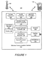
- Figure 1 is a block diagram of a wireless communication system that includes a wireless communication terminal that is configured to adaptively filter a microphone signal in response to recognition of a targeted speaker's voice in accordance with some embodiments of the present invention
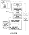
- FIG 2 is a block diagram of several components of the wireless communication terminal of Figure 1 , including the sound processor therein, that are configured in accordance with some embodiments of the present invention
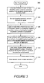
- Figure 3 is a flowchart that illustrates operations and methods during a training mode which may be carried out by the wireless communication terminal of Figure 1 to learn various characteristics of a targeted speaker's voice as the targeted speaker vocalizes a particular song/speech ;
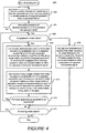
- Figure 4 is a flowchart that illustrates operations and methods during a recording mode which may be carried out by the wireless communication terminal of Figure 1 to adapt/dynamically tune filtering by an adaptive sound filter circuit in response to the learned characteristics from the training mode ;
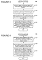
- Figure 5 is a flowchart that illustrates operations and methods during a recording mode which may be carried out by the wireless communication terminal of Figure 1 to adapt the various learned characteristics from the training mode in response to estimated distance between the terminal and a remote transmitter carried by the targeted speaker ;
- Figure 6 is a flowchart that illustrates operations and methods during a recording mode which may be carried out by the wireless communication terminal of Figure 1 to adapt the various learned characteristics from the training mode in response to estimated distance between the terminal and a person recognized in an image stream and who may be the targeted speaker or proximately located thereto.
- Some embodiments may be embodied in hardware and/or in software (including firmware, resident software, micro-code, etc.). Consequently, as used herein, the term "signal" may take the form of a continuous waveform and/or discrete value(s), such as digital value(s) in a memory or register. Furthermore, various embodiments may take the form of a computer program product on a computer-usable or computer-readable storage medium having computer-usable or computer-readable program code embodied in the medium for use by or in connection with an instruction execution system.
- circuit and “controller” may take the form of digital circuitry, such as computer-readable program code executed by an instruction processing device(s) (e.g., general purpose microprocessor and/or digital signal microprocessor), and/or analog circuitry.
- instruction processing device e.g., general purpose microprocessor and/or digital signal microprocessor
- analog circuitry e.g., analog circuitry.
- the operations that are described below with regard to Figures 4-6 can therefore be at least partially implemented as computer-readable program code executed by a computer (e.g., microprocessor).
- an electronic device includes a microphone and a sound processor.
- the microphone generates a microphone signal responsive to incident sound.
- the sound processor is configured to recognize a targeted speaker's voice within the microphone signal and to regulate filtering of the microphone signal responsive to the recognition of the targeted speaker's voice.
- terminal such as a cellular terminal, that includes a local area network (WLAN) and Bluetooth communication capability.
- WLAN local area network
- Bluetooth Bluetooth
- the present invention is not limited to such embodiments and may be embodied generally in any electronic device that filters a microphone signal, such as a sound (“audio”) recording device or audio and video recorder (e.g., camcorder), that operates in accordance with at least one embodiment described herein.
- audio sound
- video recorder e.g., camcorder
- Further non-limiting exemplary electronic devices include a digital audio recorder, a personal data assistant (PDA), digital camera, and a laptop/palmtop/desktop computer.
- Figure 1 is a block diagram of a wireless communication system 100 that includes a terminal 110 that is configured to adaptively filter a microphone signal in response to recognition of a targeted speaker's voice.
- the terminal 110 includes a microphone 112, a sound processor 114, a camera 116, and a video and sound recorder 118.
- the terminal 110 may thereby be configured as a video-sound recorder to record both video and sound.
- the terminal 110 can further include a wireless communication protocol controller 120, a cellular transceiver 122, a WLAN transceiver 124 (e.g., compliant with one or more of the IEEE 801.11 a-g standards), and a Bluetooth transceiver 126.
- the cellular transceiver 122 can be configured to communicate using one or more cellular communication protocols such as, for example, Global Standard for Mobile (GSM) communication, General Packet Radio Service (GPRS), enhanced data rates for GSM evolution (EDGE), Integrated Digital Enhancement Network (iDEN), code division multiple access (CDMA), wideband-CDMA, CDMA2000, and/or Universal Mobile Telecommunications System (UMTS).
- GSM Global Standard for Mobile
- GPRS General Packet Radio Service
- EDGE enhanced data rates for GSM evolution
- iDEN Integrated Digital Enhancement Network
- CDMA code division multiple access
- CDMA2000 wideband-CDMA2000
- UMTS Universal Mobile Telecommunications System
- the terminal 110 can further include a general application controller 128 that may control the various other components of the terminal 110, and may be configured to provide user selectable applications that are responsive to a user input interface 132 to control the video and sound recorder 118 to provide sound and video recording and playback functionality through a speaker 130 and a display 134.
- a general application controller 128 may control the various other components of the terminal 110, and may be configured to provide user selectable applications that are responsive to a user input interface 132 to control the video and sound recorder 118 to provide sound and video recording and playback functionality through a speaker 130 and a display 134.
- Various exemplary components and operations of the sound processor 114 and the microphone 112 are described below with regard to the block diagram of Figure 2 .
- the sound processor 114 is configured to recognize a targeted speaker's voice within a microphone signal 140 from the microphone 112 and to regulate filtering of the microphone signal 140 responsive to the recognition of the targeted speaker's voice.
- the sound processor 114 includes an adaptive sound filter circuit 150 and a voice recognition controller 160.
- the adaptive sound filter circuit 150 is configured to adaptively filter the microphone signal 140 responsive to a control signal 152.
- the recognition controller 160 includes a speaker recognition circuit 162, a speaker characterization circuit 164, and a repository that stores learned speaker characteristics 166.
- the repository 166 may include one or more semiconductor memories and/or other data storage devices, such as a hard disk drive and/or CD/DVD drive.
- the speaker characterization circuit 164 is configured to operate in a training mode to learn characteristics of the targeted speaker's voice component in the microphone signal 140, and to store the learned characteristics in the repository 166.
- the characteristics learned by the speaker characterization circuit 164 may include, but are not limited to, the average/maximum/minimum frequency spectrum (bandwidth), the pitch, and/or the cadence of the speaker's voice.
- the speaker recognition circuit 162 is configured to use the learned characteristics to recognize the presence of the targeted speaker's voice in the microphone signal 140 during a recording mode, which can be subsequent to the learning mode. Responsive to such recognition, the speaker recognition circuit 162 can regulate the control signal 152 to cause the adaptive sound filter circuit 150 to adapt the filtering to increase the targeted speaker's voice component relative to other components in the filtered signal 142 that is provided to an audio recorder 170 within the video and sound recorder 118.
- the adaptive sound filter circuit 150 includes a variable bandpass filter having bandpass frequencies (e.g., upper and lower attenuation corner frequencies) that are varied in response to the control signal 152.
- the speaker recognition circuit 162 can respond to recognition of the presence of the targeted speaker's voice in the microphone signal 140 by using the learned characteristics (from the repository 166) to determine a frequency range of the targeted speaker's voice and by regulating the control signal 152 to vary the bandpass frequencies of the variable bandpass filter in response to the determined frequency range.
- the bandpass filter can be tuned to increase the targeted speaker's voice component relative to other components in the filtered signal 142 in response to recognizing the presence of the targeted speaker's voice and the associated learned characteristics thereof.
- the adaptive sound filter circuit 150 includes a high-pass filter that filters the microphone signal 140.
- the high-pass filter has a cutoff frequency that is varied in response to the control signal 152.
- the speaker recognition circuit 162 can respond to recognition of the presence of the targeted speaker's voice in the microphone signal 140 by using the learned characteristics to determine a lower frequency range of the targeted speaker's voice and by regulating the control signal to vary the cutoff frequency of the high-pass filter in response to the determined lower frequency range.
- the speaker characterization circuit 164 can be configured to learn characteristics associated with the time varying pattern of the speaker's voice as the targeted speaker vocalizes a particular song/speech.
- Figure 3 is a flowchart of exemplary operations and methods 300 may be carried out by the recognition controller 160 during a learning mode in accordance with various embodiments of the present invention.
- the speaker characterization circuit 164 may cause an instruction (operation 302) to be generated on the display 134 which instructs an operator to have a targeted speaker move to the expected distance away from the terminal 110 that will be experienced during a subsequent targeted recording. In this manner, the speaker's voice during the training mode will be subjected to similar attenuation and other effects of the distance as will be experienced during a subsequent recording mode.
- the speaker characterization circuit 164 receives discrete samples (operation 304) of the targeted speaker's voice in the microphone signal 140.
- the speaker characterization circuit 164 is further configured to learn a time-varying spectral pattern of the targeted speaker's voice component in the microphone signal 140 as the targeted speaker vocalizes a particular song/speech.
- the speaker characterization circuit 164 may be configured to characterize (operation 306) the differences over time in the frequency spectrum of the targeted speaker's voice in the microphone signal 140 as the targeted speaker vocalizes the particular song/speech.
- the speaker characterization circuit 164 may alternatively or additionally be configured to characterize (operation 308) the differences over time in the amplitude of the targeted speaker's voice in the microphone signal 140 as the targeted speaker vocalizes the particular song/speech.
- the speaker characterization circuit 164 may be configured to learn the timing of gaps (operation 310) where the targeted speaker's voice in the microphone signal 140 has less than a threshold amplitude as the targeted speaker vocalizes the particular song/speech.
- the learned characteristics can be stored (operation 312) in the repository 166 for subsequent use by the speaker recognition circuit 162 during a recording mode.
- FIG 4 is a flowchart that illustrates exemplary operations and methods 400 during the recording mode which may be carried out by the speaker recognition circuit 162 to semi-statically adapt or dynamically tune the filtering by the adaptive sound filter circuit 150 in response to the learned characteristics from the training mode.
- the speaker recognition circuit 162 searches (operation 402) the sampled microphone signal using the learned characteristics from the repository 166 to attempt to identify the presence of a targeted speaker's voice component therein.
- the speaker recognition circuit 162 can be configured to use the learned time-varying spectral pattern, such as the learned variation in frequency range over time, of the targeted speaker's voice to recognize the presence of the targeted speaker's voice in the microphone signal, and which may occur while the speaker is vocalizing a previously trained song/speech.
- a further determination is then made as to whether the recognition controller 160 is operating in a song/speech mode.
- the song/speech mode may be set, for example, by a user (via the interface 132) to indicate that the filtering is to be dynamically tuned to a song/speech for which the voice characteristics have already been learned.
- the speaker recognition circuit 162 can use (operation 416) the learned characteristics from the repository 166 to semi-statically adapt (e.g., adapt responsive to initial recognition of the presence of the targeted speaker's voice) the filtering by the adaptive sound filter circuit 150 to increase the targeted speaker's voice component relative the other components of the sampled microphone signal.
- semi-statically adapt e.g., adapt responsive to initial recognition of the presence of the targeted speaker's voice
- the speaker recognition circuit 162 can respond to recognition of the targeted speaker's voice component by varying the bandpass frequencies of a variable bandpass filter and/or varying the high-pass frequency of a high-pass filter in the adaptive sound filter circuit 150 in response to the frequency range characteristics of the targeted speaker's voice.
- the adaptive sound filter circuit 150 may be configured to carry out spectral subtraction, by transforming the time-sampled microphone signal into a number of frequency bins using a fast Fourier transform (FFT), and attenuating signal energy in frequency bins that are outside the learned frequency spectrum of the targeted speaker's voice.
- FFT fast Fourier transform
- the speaker recognition circuit 162 can use (operation 408) the learned characteristics from the repository 166 to dynamically tune the adaptive sound filter circuit 150 to track the expected characteristic variations over time in the frequency range and/or in the an amplitude of the targeted speaker's voice during the song/speech to increase the targeted speaker's voice component relative to other components of the sampled microphone signal.
- the speaker recognition circuit 162 may, for example, regulate the control signal 152 to cause the adaptive sound filter circuit 150 to dynamically vary the frequency range of the bandpass filter and/or vary the high-pass frequency of the high-pass filter to track the expected changes over time in the targeted speaker's voice characteristics during the trained song/speech.
- the speaker recognition circuit 162 may regulate the control signal 152 to dynamically tune the gain of a variable gain amplifier in the adaptive sound filter circuit 150 that amplifies the microphone signal 140 to dynamically compensate for (e.g., track) the expected changes over time in the amplitude of the targeted speaker's voice during the trained song/speech.
- the speaker recognition circuit 162 may, for example, compensate for an expected decrease in the targeted speaker's voice at a particular instance in time by increasing the amplification gain that is applied to all components of the microphone signal 140 or that is supplied to a specific spectral component of the microphone signal 140 that has been learned to be characteristic of the targeted speaker's voice at that instant in time.
- the speaker recognition circuit 162 may also use (operation 410) the learned timing of gaps, recalled from the repository 166, to dynamically tune the adaptive sound filter circuit 150 to increase the targeted speaker's voice component relative to other components of the sample microphone signal in-between each of the gaps, and to decrease the targeted speaker's voice component relative to the other components during each of the gaps.
- the adaptive sound filter circuit 150 can be tuned to reduce the filtering of the microphone signal 140 or to more neutrally apply the filtering with less bias toward the characteristics of the targeted speaker.
- the speaker recognition circuit 162 may regulate the control signal 152 to cause the adaptive sound filter circuit 150 to expand the frequency range of the bandpass filter, lower the high-pass frequency of the high-pass filter, and/or increase/decrease the gain applied by the amplifier.
- the speaker recognition circuit 162 can loop back to repeat the operations 408 and 410.
- a further determination is made (operation 414) as to whether the recording mode is still active and, when it is, the speaker recognition circuit 162 can loop back to repeat the determination operation 406 and the associated subsequent operations.
- the sound processor 114 can further include a distance determination circuit 180 that is configured to determine the distance between the terminal 110 and a remote transmitter that can be carried by the targeted speaker.
- the distance determination circuit 180 can include a received signal strength (RSS) based distance measurement circuit 182 that is configured to determine signal strength of a communication signal received by, for example, the WLAN transceiver 124 and/or the Bluetooth transceiver 126.
- the RSS based distance measurement circuit 182 can estimate distance from the terminal 110 to the remote transmitter in response to the RSS.
- Figure 5 is a flowchart that illustrates exemplary operations and methods 500 that may be carried out by the sound processor 114 to determine the distance between the terminal 110 and a remote transmitter carried by the targeted speaker and, responsive thereto, to adapt how the various learned characteristics in the repository 166 are used to control the adaptive sound filter circuit 150 compensate for the expected effects of the distance on the characteristics of the targeted speaker's voice component in the microphone signal 140.
- a wireless communication signal is received (operation 502) from a remote transmitter that can be carried by the targeted speaker.
- the terminal 110 and the remote transmitter may communicate through a wireless local area network (WLAN) and/or through a Bluetooth network via the WLAN transceiver 124 and/or the Bluetooth transceiver 126, respectively.
- the remote transmitter may be a cellular telephone or PDA with a Bluetooth transceiver and/or WLAN transceiver that is networked to the terminal 110 and which may, for example, be in a clothes pocket of the targeted speaker.
- the RSS based distance measurement circuit 182 determines the strength of the received signal (operation 504), and estimates (operation 506) the distance from the terminal 110 to the remote transmitter in response to the received signal strength.
- the RSS distance circuit 182 may estimate the distance using a defined relationship between an expected strength of the signal transmitted by the remote transmitter and the strength of the signal that is received by terminal 110. For example, a Bluetooth transceiver and/or a WLAN transceiver within the remote transmitter can be expected to transmit with a relatively constant signal strength.
- the RSS distance circuit 182 can determine the distance between the terminal 110 and the remote transmitter in response to the expected strength of the remote transmitter's transmitted signal and the strength of the signal that is received by the Bluetooth transceiver 126 and/or the WLAN transceiver 124. Based on the transmission pattern and associated gain of the transmitting antenna and the receiving antenna, the transmitted and received signal strength may be related by the distance squared or the distance cubed.
- the speaker characterization circuit 164 and/or the speaker recognition circuit 162 can be further configured to adapt (operation 508) the learned characteristics of the targeted speaker's voice in response to the estimated distance from the terminal 110 to the remote transmitter to compensate for the expected effects of distance on the characteristics of the targeted speaker's voice component in the microphone signal 140.
- the adaptive sound filter circuit 150 can be tuned (via the circuits 160 and 180) to increase the amplification gain applied to the microphone signal 140 to compensate for the expected decrease in the amplitude of the targeted speaker's voice at the determined distance.
- the adaptive sound filter circuit 150 can be tuned (via the circuits 160 and 180) to the expected frequency range of the targeted speaker's voice at that distance, such as by moving the corner frequencies of the bandpass filtered to narrow the pass-through frequency range in the filtered signal 142 to correspond to the expected decrease in the frequency range of the targeted speaker's voice at the determined distance.
- the adaptive sound filter circuit 150 can be tuned (via the circuits 160 and 180) to decreasing the high-pass frequency of the high-pass filter to allow lower frequencies to pass-through to the filtered signal 142 to compensate for the expected lowering of the frequency of the targeted speaker's voice at the determined distance.
- Figure 6 is a flowchart that illustrates additional or alternative exemplary operations and methods 500 that may be carried out by the sound processor 114 during the recording mode to determine the distance between the terminal 110 and a person within an image stream from the camera 116 and, responsive thereto, to adapt how the various learned characteristics in the repository 166 are used to control the adaptive sound filter circuit 150 to compensate for the expected effects of the distance on the characteristics of the targeted speaker's voice component in the microphone signal 140.
- the distance determination circuit 180 can include a circuit 184 that determines the size of a person's image in the image signal from the camera 116 and, responsive thereto, determines the distance between the terminal 110 and the person's image in the image stream from the camera 116 based on the size of the person's image.
- the image signal can also be routed to a video recorder 172, within the video and sound recorder 118, for recording therein.
- the circuit 184 is configured to recognize (operation 602) in the image signal the presence of a person, who may correspond to the targeted speaker or be proximately located to the targeted speaker.
- the circuit 184 can further estimate (operation 604) the distance from the terminal 110 to the person in response to the size of the person relative to a plurality of threshold values, where the threshold values may relate image size to expected distance.
- the circuit 184 may further account for a zoom setting of the camera 116 (when available) during the distance estimation.
- the speaker characterization circuit 164 and/or the speaker recognition circuit 162 can be further configured to adapt (operation 606) the learned characteristics of the targeted speaker's voice in response to the estimated distance from the terminal 110 to the person to compensate for the expected effects of distance on the characteristics of the targeted speaker's voice component in the microphone signal 140, such as described above with regard to operation 508 of Figure 5 .
- the microphone 112 can be configured as a zoom/beam steerable microphone having a plurality of microphone elements 190a and 190b and a controllable phase combiner circuit 192 that adjusts the relative phase between signals from the microphone elements 190a and 190b in response to a phase control signal 194 and combines the adjusted phase signals to generate the microphone signal 140.
- the recognition controller 160 can be configured to regulate the phase control signal 194 in response to recognizing the presence of the targeted speaker's voice in the microphone signal 140 and the estimated distance from the terminal 110 to the remote transmitter and/or the person recognized in the image signal to zoom or steer the combined sensitivity of the microphone elements 190a and 190b responsive to the distance to the targeted speaker.
- the microphone 112 may thereby be controlled to assist with increasing the targeted speaker's voice component relative to other components in the microphone signal 140.
Landscapes
- Engineering & Computer Science (AREA)
- Multimedia (AREA)
- Audiology, Speech & Language Pathology (AREA)
- Human Computer Interaction (AREA)
- Physics & Mathematics (AREA)
- Acoustics & Sound (AREA)
- Health & Medical Sciences (AREA)
- Computational Linguistics (AREA)
- Quality & Reliability (AREA)
- Signal Processing (AREA)
- Circuit For Audible Band Transducer (AREA)
- Filters That Use Time-Delay Elements (AREA)
- Telephone Function (AREA)
Claims (4)
- Eine elektronische Vorrichtung umfassend:ein Mikrofon, das konfiguriert ist, ein Mikrofonsignal als Reaktion auf ankommenden Ton zu generieren; undeinen Tonprozessor, der konfiguriert ist, innerhalb des Mikrofonsignals die Stimme eines ausgewählten Sprechers zu erkennen und eine Filterung des Mikrofonsignals als Reaktion auf die Erkennung der Stimme des ausgewählten Sprechers zu regulieren,wobei der Tonprozessor umfasst:eine Sprechercharakterisierungsschaltung, welche konfiguriert ist, in einem Trainingsmodus zu arbeiten, um, während der ausgewählte Sprecher ein bestimmtes Lied/eine bestimmte Rede vokalisiert, von der Komponente der Stimme des ausgewählten Sprechers im Mikrofonsignal ein zeitabhängiges Spektralmuster der Stimme des ausgewählten Sprechers zu lernen, und das zeitabhängige Spektralmuster zu speichern,eine anpassungsfähige Tonfilterschaltung, welche konfiguriert ist, das Mikrofonsignal als Reaktion auf ein Kontrollsignal anpassungsfähig zu filtern; undeine Sprechererkennungsschaltung, welche konfiguriert ist, das gelernte zeitabhängige Spektralmuster zu verwenden, um die Anwesenheit der Stimme des ausgewählten Sprechers, welche das bestimmte Lied/die bestimmte Rede vokalisiert, im Mikrofonsignal zu erkennen, und auf die erkannte Anwesenheit durch Verwendung des gelernten zeitabhängigen Spektralmusters zu reagieren, um das Kontrollsignal im zeitlichen Verlauf zu variieren, um die anpassungsfähige Tonfilterschaltung dynamisch einzustellen, um das erwartete zeitabhängige Spektralmuster der Stimme des ausgewählten Sprechers während des Liedes/der Rede zu verfolgen und um die Komponente der Stimme des ausgewählten Sprechers im Mikrofon in Bezug auf andere Komponenten zu erhöhen.
- Die elektronische Vorrichtung nach Anspruch 1, wobei:die anpassungsfähige Tonfilterschaltung einen variablen Bandpassfilter mit Bandpassfrequenzen umfasst, die als Antwort auf das Kontrollsignal variiert werden;die Sprechercharakterisierungsschaltung weiterhin konfiguriert ist, während der ausgewählte Sprecher das bestimmte Lied/die bestimmte Rede vokalisiert, das zeitabhängige Spektralmuster mittels Charakterisierung von Unterschieden im zeitlichen Verlauf des Frequenzbereichs der Stimme des ausgewählten Sprechers im Mikrofonsignal zu lernen; unddie Sprechererkennungsschaltung weiterhin konfiguriert ist, das gelernte zeitabhängige Spektralmuster zu verwenden, um die Bandpassfrequenzen des Bandpassfilters derart einzustellen, dass sie den Unterschieden im zeitlichen Verlauf des Frequenzbereichs der Stimme des ausgewählten Sprechers folgen, um dadurch, während dem bestimmten Lied/der bestimmten Rede, die Komponente der Stimme des ausgewählten Sprechers im Mikrofonsignal in Bezug auf andere Komponenten zu erhöhen.
- Die elektronische Vorrichtung nach einem der Ansprüche 1 und 2, wobei:die Sprechercharakterisierungsschaltung weiterhin konfiguriert ist, die Zeiteinteilung von Unterbrechungen zu lernen, in denen, während der ausgewählte Sprecher das bestimmte Lied/die bestimmte Rede vokalisiert, die Stimme des ausgewählten Sprechers im Mikrofonsignal kleiner als eine Schwellwertamplitude ist; unddie Sprechererkennungsschaltung weiterhin konfiguriert ist,die gelernte Unterbrechungszeiteinteilung zu verwenden, um das Kontrollsignal im zeitlichen Verlauf zu variieren, um die anderen Komponenten des Mikrofonsignals in Bezug auf die Komponente der Stimme des ausgewählten Sprechers im Mikrofonsignal während jeder dieser Unterbrechungen zu erhöhen und die Komponente der Stimme des ausgewählten Sprechers in Bezug auf die anderen Komponenten des Mikrofonsignals zwischen jeder Unterbrechung zu erhöhen.
- Die elektronische Vorrichtung nach einem der Ansprüche 1-3, wobei:die anpassungsfähige Tonfilterschaltung einen Verstärker mit variabler Verstärkung umfasst, der konfiguriert ist, das Mikrofonsignal zu verstärken und eine Verstärkung hat, die als Antwort auf das Kontrollsignal variiert wird;die Sprechercharakterisierungsschaltung weiterhin konfiguriert ist, während des Trainingsmodus zu arbeiten, um von der Komponente der Stimme des ausgewählten Sprechers im Mikrofonsignal ein zeitabhängiges Amplitudenmuster der Stimme des ausgewählten Sprechers zu lernen, während der ausgewählte Sprecher das bestimmte Lied/die bestimmte Rede vokalisiert; unddie Sprechererkennungsschaltung weiterhin konfiguriert ist, auf die erkannte Anwesenheit der Stimme des ausgewählten Sprechers zu reagieren, indem sie das gelernte zeitabhängige Amplitudenmuster verwendet, um das Kontrollsignal im zeitlichen Verlauf zu variieren, um die Verstärkung des Verstärkers mit variabler Verstärkung dynamisch einzustellen, um das erwartete zeitabhängige Amplitudenmuster der Stimme des ausgewählten Sprechers während des bestimmten Liedes/der bestimmten Rede zu verfolgen.
Applications Claiming Priority (2)
| Application Number | Priority Date | Filing Date | Title |
|---|---|---|---|
| US12/038,118 US7974841B2 (en) | 2008-02-27 | 2008-02-27 | Electronic devices and methods that adapt filtering of a microphone signal responsive to recognition of a targeted speaker's voice |
| PCT/IB2008/002283 WO2009106918A1 (en) | 2008-02-27 | 2008-09-02 | Electronic devices and methods that adapt filtering of a microphone signal responsive to recognition of a targeted speaker's voice |
Publications (2)
| Publication Number | Publication Date |
|---|---|
| EP2245618A1 EP2245618A1 (de) | 2010-11-03 |
| EP2245618B1 true EP2245618B1 (de) | 2011-08-03 |
Family
ID=40149544
Family Applications (1)
| Application Number | Title | Priority Date | Filing Date |
|---|---|---|---|
| EP08806978A Not-in-force EP2245618B1 (de) | 2008-02-27 | 2008-09-02 | Elektronische vorrichtung, das die filterung eines mikrofonsignals als reaktion auf die erkennung der stimme eines ausgewählten sprechers anpasst |
Country Status (5)
| Country | Link |
|---|---|
| US (1) | US7974841B2 (de) |
| EP (1) | EP2245618B1 (de) |
| CN (1) | CN101952884B (de) |
| AT (1) | ATE519195T1 (de) |
| WO (1) | WO2009106918A1 (de) |
Families Citing this family (24)
| Publication number | Priority date | Publication date | Assignee | Title |
|---|---|---|---|---|
| US8655660B2 (en) * | 2008-12-11 | 2014-02-18 | International Business Machines Corporation | Method for dynamic learning of individual voice patterns |
| US20100153116A1 (en) * | 2008-12-12 | 2010-06-17 | Zsolt Szalai | Method for storing and retrieving voice fonts |
| JP5418061B2 (ja) * | 2009-08-20 | 2014-02-19 | 沖電気工業株式会社 | 遠隔コミュニケーション装置、遠隔コミュニケーション方法、および遠隔コミュニケーションシステム |
| CN101950564A (zh) * | 2010-10-13 | 2011-01-19 | 镇江华扬信息科技有限公司 | 一种远程数字化语音采集分析识别系统 |
| EP2528356A1 (de) * | 2011-05-25 | 2012-11-28 | Oticon A/s | Sprachabhängige Ausgleichsstrategie |
| US9037461B2 (en) * | 2012-01-19 | 2015-05-19 | SpeakWrite, LLC | Methods and systems for dictation and transcription |
| US20140095161A1 (en) * | 2012-09-28 | 2014-04-03 | At&T Intellectual Property I, L.P. | System and method for channel equalization using characteristics of an unknown signal |
| WO2014112206A1 (ja) * | 2013-01-15 | 2014-07-24 | ソニー株式会社 | 記憶制御装置、再生制御装置および記録媒体 |
| US11199906B1 (en) | 2013-09-04 | 2021-12-14 | Amazon Technologies, Inc. | Global user input management |
| CN104464746A (zh) * | 2013-09-12 | 2015-03-25 | 索尼公司 | 语音滤波方法、装置以及电子设备 |
| CN105895104B (zh) * | 2014-05-04 | 2019-09-03 | 讯飞智元信息科技有限公司 | 说话人自适应识别方法及系统 |
| US9904851B2 (en) | 2014-06-11 | 2018-02-27 | At&T Intellectual Property I, L.P. | Exploiting visual information for enhancing audio signals via source separation and beamforming |
| US9437193B2 (en) * | 2015-01-21 | 2016-09-06 | Microsoft Technology Licensing, Llc | Environment adjusted speaker identification |
| US10014137B2 (en) | 2015-10-03 | 2018-07-03 | At&T Intellectual Property I, L.P. | Acoustical electrical switch |
| US9704489B2 (en) | 2015-11-20 | 2017-07-11 | At&T Intellectual Property I, L.P. | Portable acoustical unit for voice recognition |
| CN106952654A (zh) * | 2017-04-24 | 2017-07-14 | 北京奇虎科技有限公司 | 机器人降噪方法、装置及机器人 |
| US10334358B2 (en) * | 2017-06-08 | 2019-06-25 | Dts, Inc. | Correcting for a latency of a speaker |
| DE102017215938A1 (de) * | 2017-09-11 | 2019-03-14 | Robert Bosch Gmbh | Verfahren und Vorrichtung zum Verarbeiten eines Signals |
| GB2581596B (en) * | 2017-10-10 | 2021-12-01 | Cirrus Logic Int Semiconductor Ltd | Headset on ear state detection |
| US10878824B2 (en) * | 2018-02-21 | 2020-12-29 | Valyant Al, Inc. | Speech-to-text generation using video-speech matching from a primary speaker |
| JP6635394B1 (ja) * | 2019-01-29 | 2020-01-22 | パナソニックIpマネジメント株式会社 | 音声処理装置および音声処理方法 |
| US11094328B2 (en) * | 2019-09-27 | 2021-08-17 | Ncr Corporation | Conferencing audio manipulation for inclusion and accessibility |
| CN114333896B (zh) | 2020-09-25 | 2025-07-01 | 华为技术有限公司 | 语音分离方法、电子设备、芯片及计算机可读存储介质 |
| CN116564335A (zh) * | 2023-04-13 | 2023-08-08 | 阿里巴巴(中国)有限公司 | 音频处理方法和音频处理设备 |
Family Cites Families (15)
| Publication number | Priority date | Publication date | Assignee | Title |
|---|---|---|---|---|
| DE19811879C1 (de) | 1998-03-18 | 1999-05-12 | Siemens Ag | Einrichtung und Verfahren zum Erkennen von Sprache |
| US6963937B1 (en) * | 1998-12-17 | 2005-11-08 | International Business Machines Corporation | Method and apparatus for providing configurability and customization of adaptive user-input filtration |
| US7206418B2 (en) | 2001-02-12 | 2007-04-17 | Fortemedia, Inc. | Noise suppression for a wireless communication device |
| US7123727B2 (en) * | 2001-07-18 | 2006-10-17 | Agere Systems Inc. | Adaptive close-talking differential microphone array |
| GB2393350B (en) * | 2001-07-25 | 2006-03-08 | Neil J Stevenson | A camera control apparatus and method |
| US7027832B2 (en) | 2001-11-28 | 2006-04-11 | Qualcomm Incorporated | Providing custom audio profile in wireless device |
| KR100628569B1 (ko) | 2002-02-09 | 2006-09-26 | 삼성전자주식회사 | 복수의 음향취득장치가 결합 가능한 캠코더 |
| WO2004053839A1 (en) | 2002-12-11 | 2004-06-24 | Softmax, Inc. | System and method for speech processing using independent component analysis under stability constraints |
| US7068797B2 (en) | 2003-05-20 | 2006-06-27 | Sony Ericsson Mobile Communications Ab | Microphone circuits having adjustable directivity patterns for reducing loudspeaker feedback and methods of operating the same |
| US7720683B1 (en) * | 2003-06-13 | 2010-05-18 | Sensory, Inc. | Method and apparatus of specifying and performing speech recognition operations |
| US7054436B2 (en) | 2004-08-02 | 2006-05-30 | Sony Ericsson Mobile Communication, Ab | Communication terminals with a dual use speaker for sensing background noise and generating sound, and related methods and computer program products |
| ATE491503T1 (de) | 2005-05-05 | 2011-01-15 | Sony Computer Entertainment Inc | Videospielsteuerung mittels joystick |
| US8214208B2 (en) * | 2006-09-28 | 2012-07-03 | Reqall, Inc. | Method and system for sharing portable voice profiles |
| JP4264841B2 (ja) * | 2006-12-01 | 2009-05-20 | ソニー株式会社 | 音声認識装置および音声認識方法、並びに、プログラム |
| PT2171712T (pt) * | 2007-06-27 | 2016-09-28 | ERICSSON TELEFON AB L M (publ) | Método e disposição para melhorar sinais áudio espaciais |
-
2008
- 2008-02-27 US US12/038,118 patent/US7974841B2/en not_active Expired - Fee Related
- 2008-09-02 AT AT08806978T patent/ATE519195T1/de not_active IP Right Cessation
- 2008-09-02 CN CN2008801274321A patent/CN101952884B/zh not_active Expired - Fee Related
- 2008-09-02 EP EP08806978A patent/EP2245618B1/de not_active Not-in-force
- 2008-09-02 WO PCT/IB2008/002283 patent/WO2009106918A1/en not_active Ceased
Also Published As
| Publication number | Publication date |
|---|---|
| CN101952884A (zh) | 2011-01-19 |
| US20090216529A1 (en) | 2009-08-27 |
| US7974841B2 (en) | 2011-07-05 |
| ATE519195T1 (de) | 2011-08-15 |
| EP2245618A1 (de) | 2010-11-03 |
| CN101952884B (zh) | 2012-04-04 |
| WO2009106918A1 (en) | 2009-09-03 |
Similar Documents
| Publication | Publication Date | Title |
|---|---|---|
| EP2245618B1 (de) | Elektronische vorrichtung, das die filterung eines mikrofonsignals als reaktion auf die erkennung der stimme eines ausgewählten sprechers anpasst | |
| US9113240B2 (en) | Speech enhancement using multiple microphones on multiple devices | |
| CN104272380B (zh) | 在具有适应性噪音消除(anc)的个人音频设备中的频率和方向相关周围声音处理 | |
| CA2560034C (en) | System for selectively extracting components of an audio input signal | |
| US20060115095A1 (en) | Reverberation estimation and suppression system | |
| CN104243732A (zh) | 振动传感器在回声消除中的使用 | |
| WO2011001010A1 (en) | Apparatus, method and computer program for controlling an acoustic signal | |
| US20200296534A1 (en) | Sound playback device and output sound adjusting method thereof | |
| US11871193B2 (en) | Microphone system | |
| US20190379972A1 (en) | Techniques for howling detection | |
| CN115412803A (zh) | 音频信号补偿方法及装置、耳机、存储介质 | |
| US8275141B2 (en) | Noise reduction system and noise reduction method | |
| JP2010085913A (ja) | 音補正装置 | |
| JP2586847B2 (ja) | 電子電話機 | |
| US12075217B2 (en) | Signal processing methods and systems for adaptive beam forming | |
| US12114136B2 (en) | Signal processing methods and systems for beam forming with microphone tolerance compensation | |
| US12342136B2 (en) | Signal processing methods and system for beam forming with improved signal to noise ratio | |
| CN114613380B (zh) | 一种录音的方法、装置、设备及存储介质 | |
| US11875769B2 (en) | Baby monitor system with noise filtering and method thereof | |
| CN115810362A (zh) | 会议终端及反馈抑制方法 |
Legal Events
| Date | Code | Title | Description |
|---|---|---|---|
| PUAI | Public reference made under article 153(3) epc to a published international application that has entered the european phase |
Free format text: ORIGINAL CODE: 0009012 |
|
| 17P | Request for examination filed |
Effective date: 20100818 |
|
| AK | Designated contracting states |
Kind code of ref document: A1 Designated state(s): AT BE BG CH CY CZ DE DK EE ES FI FR GB GR HR HU IE IS IT LI LT LU LV MC MT NL NO PL PT RO SE SI SK TR |
|
| AX | Request for extension of the european patent |
Extension state: AL BA MK RS |
|
| GRAP | Despatch of communication of intention to grant a patent |
Free format text: ORIGINAL CODE: EPIDOSNIGR1 |
|
| RTI1 | Title (correction) |
Free format text: ELECTRONIC DEVICE THAT ADAPTS FILTERING OF A MICROPHONE SIGNAL RESPONSIVE TO RECOGNITION OF A TARGETED SPEAKER'S VOICE |
|
| DAX | Request for extension of the european patent (deleted) | ||
| GRAS | Grant fee paid |
Free format text: ORIGINAL CODE: EPIDOSNIGR3 |
|
| GRAA | (expected) grant |
Free format text: ORIGINAL CODE: 0009210 |
|
| AK | Designated contracting states |
Kind code of ref document: B1 Designated state(s): AT BE BG CH CY CZ DE DK EE ES FI FR GB GR HR HU IE IS IT LI LT LU LV MC MT NL NO PL PT RO SE SI SK TR |
|
| REG | Reference to a national code |
Ref country code: GB Ref legal event code: FG4D |
|
| REG | Reference to a national code |
Ref country code: CH Ref legal event code: EP |
|
| REG | Reference to a national code |
Ref country code: IE Ref legal event code: FG4D |
|
| REG | Reference to a national code |
Ref country code: DE Ref legal event code: R096 Ref document number: 602008008696 Country of ref document: DE Effective date: 20111006 |
|
| REG | Reference to a national code |
Ref country code: NL Ref legal event code: T3 |
|
| LTIE | Lt: invalidation of european patent or patent extension |
Effective date: 20110803 |
|
| PG25 | Lapsed in a contracting state [announced via postgrant information from national office to epo] |
Ref country code: PT Free format text: LAPSE BECAUSE OF FAILURE TO SUBMIT A TRANSLATION OF THE DESCRIPTION OR TO PAY THE FEE WITHIN THE PRESCRIBED TIME-LIMIT Effective date: 20111205 Ref country code: NO Free format text: LAPSE BECAUSE OF FAILURE TO SUBMIT A TRANSLATION OF THE DESCRIPTION OR TO PAY THE FEE WITHIN THE PRESCRIBED TIME-LIMIT Effective date: 20111103 Ref country code: HR Free format text: LAPSE BECAUSE OF FAILURE TO SUBMIT A TRANSLATION OF THE DESCRIPTION OR TO PAY THE FEE WITHIN THE PRESCRIBED TIME-LIMIT Effective date: 20110803 Ref country code: IS Free format text: LAPSE BECAUSE OF FAILURE TO SUBMIT A TRANSLATION OF THE DESCRIPTION OR TO PAY THE FEE WITHIN THE PRESCRIBED TIME-LIMIT Effective date: 20111203 Ref country code: LT Free format text: LAPSE BECAUSE OF FAILURE TO SUBMIT A TRANSLATION OF THE DESCRIPTION OR TO PAY THE FEE WITHIN THE PRESCRIBED TIME-LIMIT Effective date: 20110803 Ref country code: FI Free format text: LAPSE BECAUSE OF FAILURE TO SUBMIT A TRANSLATION OF THE DESCRIPTION OR TO PAY THE FEE WITHIN THE PRESCRIBED TIME-LIMIT Effective date: 20110803 Ref country code: SE Free format text: LAPSE BECAUSE OF FAILURE TO SUBMIT A TRANSLATION OF THE DESCRIPTION OR TO PAY THE FEE WITHIN THE PRESCRIBED TIME-LIMIT Effective date: 20110803 |
|
| REG | Reference to a national code |
Ref country code: AT Ref legal event code: MK05 Ref document number: 519195 Country of ref document: AT Kind code of ref document: T Effective date: 20110803 |
|
| PG25 | Lapsed in a contracting state [announced via postgrant information from national office to epo] |
Ref country code: CY Free format text: LAPSE BECAUSE OF FAILURE TO SUBMIT A TRANSLATION OF THE DESCRIPTION OR TO PAY THE FEE WITHIN THE PRESCRIBED TIME-LIMIT Effective date: 20110803 Ref country code: SI Free format text: LAPSE BECAUSE OF FAILURE TO SUBMIT A TRANSLATION OF THE DESCRIPTION OR TO PAY THE FEE WITHIN THE PRESCRIBED TIME-LIMIT Effective date: 20110803 Ref country code: GR Free format text: LAPSE BECAUSE OF FAILURE TO SUBMIT A TRANSLATION OF THE DESCRIPTION OR TO PAY THE FEE WITHIN THE PRESCRIBED TIME-LIMIT Effective date: 20111104 Ref country code: AT Free format text: LAPSE BECAUSE OF FAILURE TO SUBMIT A TRANSLATION OF THE DESCRIPTION OR TO PAY THE FEE WITHIN THE PRESCRIBED TIME-LIMIT Effective date: 20110803 Ref country code: PL Free format text: LAPSE BECAUSE OF FAILURE TO SUBMIT A TRANSLATION OF THE DESCRIPTION OR TO PAY THE FEE WITHIN THE PRESCRIBED TIME-LIMIT Effective date: 20110803 Ref country code: LV Free format text: LAPSE BECAUSE OF FAILURE TO SUBMIT A TRANSLATION OF THE DESCRIPTION OR TO PAY THE FEE WITHIN THE PRESCRIBED TIME-LIMIT Effective date: 20110803 |
|
| PG25 | Lapsed in a contracting state [announced via postgrant information from national office to epo] |
Ref country code: BE Free format text: LAPSE BECAUSE OF FAILURE TO SUBMIT A TRANSLATION OF THE DESCRIPTION OR TO PAY THE FEE WITHIN THE PRESCRIBED TIME-LIMIT Effective date: 20110803 |
|
| PG25 | Lapsed in a contracting state [announced via postgrant information from national office to epo] |
Ref country code: CZ Free format text: LAPSE BECAUSE OF FAILURE TO SUBMIT A TRANSLATION OF THE DESCRIPTION OR TO PAY THE FEE WITHIN THE PRESCRIBED TIME-LIMIT Effective date: 20110803 Ref country code: SK Free format text: LAPSE BECAUSE OF FAILURE TO SUBMIT A TRANSLATION OF THE DESCRIPTION OR TO PAY THE FEE WITHIN THE PRESCRIBED TIME-LIMIT Effective date: 20110803 Ref country code: MC Free format text: LAPSE BECAUSE OF NON-PAYMENT OF DUE FEES Effective date: 20110930 |
|
| PG25 | Lapsed in a contracting state [announced via postgrant information from national office to epo] |
Ref country code: IT Free format text: LAPSE BECAUSE OF FAILURE TO SUBMIT A TRANSLATION OF THE DESCRIPTION OR TO PAY THE FEE WITHIN THE PRESCRIBED TIME-LIMIT Effective date: 20110803 Ref country code: EE Free format text: LAPSE BECAUSE OF FAILURE TO SUBMIT A TRANSLATION OF THE DESCRIPTION OR TO PAY THE FEE WITHIN THE PRESCRIBED TIME-LIMIT Effective date: 20110803 Ref country code: RO Free format text: LAPSE BECAUSE OF FAILURE TO SUBMIT A TRANSLATION OF THE DESCRIPTION OR TO PAY THE FEE WITHIN THE PRESCRIBED TIME-LIMIT Effective date: 20110803 |
|
| PLBE | No opposition filed within time limit |
Free format text: ORIGINAL CODE: 0009261 |
|
| STAA | Information on the status of an ep patent application or granted ep patent |
Free format text: STATUS: NO OPPOSITION FILED WITHIN TIME LIMIT |
|
| REG | Reference to a national code |
Ref country code: IE Ref legal event code: MM4A |
|
| PG25 | Lapsed in a contracting state [announced via postgrant information from national office to epo] |
Ref country code: DK Free format text: LAPSE BECAUSE OF FAILURE TO SUBMIT A TRANSLATION OF THE DESCRIPTION OR TO PAY THE FEE WITHIN THE PRESCRIBED TIME-LIMIT Effective date: 20110803 |
|
| 26N | No opposition filed |
Effective date: 20120504 |
|
| PG25 | Lapsed in a contracting state [announced via postgrant information from national office to epo] |
Ref country code: IE Free format text: LAPSE BECAUSE OF NON-PAYMENT OF DUE FEES Effective date: 20110902 |
|
| REG | Reference to a national code |
Ref country code: DE Ref legal event code: R097 Ref document number: 602008008696 Country of ref document: DE Effective date: 20120504 |
|
| PG25 | Lapsed in a contracting state [announced via postgrant information from national office to epo] |
Ref country code: MT Free format text: LAPSE BECAUSE OF FAILURE TO SUBMIT A TRANSLATION OF THE DESCRIPTION OR TO PAY THE FEE WITHIN THE PRESCRIBED TIME-LIMIT Effective date: 20110803 |
|
| PG25 | Lapsed in a contracting state [announced via postgrant information from national office to epo] |
Ref country code: ES Free format text: LAPSE BECAUSE OF FAILURE TO SUBMIT A TRANSLATION OF THE DESCRIPTION OR TO PAY THE FEE WITHIN THE PRESCRIBED TIME-LIMIT Effective date: 20111114 |
|
| REG | Reference to a national code |
Ref country code: CH Ref legal event code: PL |
|
| PG25 | Lapsed in a contracting state [announced via postgrant information from national office to epo] |
Ref country code: LU Free format text: LAPSE BECAUSE OF NON-PAYMENT OF DUE FEES Effective date: 20110902 |
|
| PG25 | Lapsed in a contracting state [announced via postgrant information from national office to epo] |
Ref country code: BG Free format text: LAPSE BECAUSE OF FAILURE TO SUBMIT A TRANSLATION OF THE DESCRIPTION OR TO PAY THE FEE WITHIN THE PRESCRIBED TIME-LIMIT Effective date: 20111103 |
|
| PG25 | Lapsed in a contracting state [announced via postgrant information from national office to epo] |
Ref country code: CH Free format text: LAPSE BECAUSE OF NON-PAYMENT OF DUE FEES Effective date: 20120930 Ref country code: LI Free format text: LAPSE BECAUSE OF NON-PAYMENT OF DUE FEES Effective date: 20120930 |
|
| PG25 | Lapsed in a contracting state [announced via postgrant information from national office to epo] |
Ref country code: TR Free format text: LAPSE BECAUSE OF FAILURE TO SUBMIT A TRANSLATION OF THE DESCRIPTION OR TO PAY THE FEE WITHIN THE PRESCRIBED TIME-LIMIT Effective date: 20110803 |
|
| PG25 | Lapsed in a contracting state [announced via postgrant information from national office to epo] |
Ref country code: HU Free format text: LAPSE BECAUSE OF FAILURE TO SUBMIT A TRANSLATION OF THE DESCRIPTION OR TO PAY THE FEE WITHIN THE PRESCRIBED TIME-LIMIT Effective date: 20110803 |
|
| PGFP | Annual fee paid to national office [announced via postgrant information from national office to epo] |
Ref country code: NL Payment date: 20140910 Year of fee payment: 7 Ref country code: DE Payment date: 20140827 Year of fee payment: 7 |
|
| PGFP | Annual fee paid to national office [announced via postgrant information from national office to epo] |
Ref country code: GB Payment date: 20140827 Year of fee payment: 7 |
|
| PGFP | Annual fee paid to national office [announced via postgrant information from national office to epo] |
Ref country code: FR Payment date: 20140906 Year of fee payment: 7 |
|
| REG | Reference to a national code |
Ref country code: DE Ref legal event code: R119 Ref document number: 602008008696 Country of ref document: DE |
|
| GBPC | Gb: european patent ceased through non-payment of renewal fee |
Effective date: 20150902 |
|
| REG | Reference to a national code |
Ref country code: NL Ref legal event code: MM Effective date: 20151001 |
|
| REG | Reference to a national code |
Ref country code: FR Ref legal event code: ST Effective date: 20160531 |
|
| PG25 | Lapsed in a contracting state [announced via postgrant information from national office to epo] |
Ref country code: GB Free format text: LAPSE BECAUSE OF NON-PAYMENT OF DUE FEES Effective date: 20150902 Ref country code: DE Free format text: LAPSE BECAUSE OF NON-PAYMENT OF DUE FEES Effective date: 20160401 |
|
| PG25 | Lapsed in a contracting state [announced via postgrant information from national office to epo] |
Ref country code: FR Free format text: LAPSE BECAUSE OF NON-PAYMENT OF DUE FEES Effective date: 20150930 Ref country code: NL Free format text: LAPSE BECAUSE OF NON-PAYMENT OF DUE FEES Effective date: 20151001 |