EP2245268B1 - Method for self-adjusting (autonomously adjusting) the flow of a fluid through a valve or flow control device in injectors in oil production - Google Patents
Method for self-adjusting (autonomously adjusting) the flow of a fluid through a valve or flow control device in injectors in oil production Download PDFInfo
- Publication number
- EP2245268B1 EP2245268B1 EP20080870295 EP08870295A EP2245268B1 EP 2245268 B1 EP2245268 B1 EP 2245268B1 EP 20080870295 EP20080870295 EP 20080870295 EP 08870295 A EP08870295 A EP 08870295A EP 2245268 B1 EP2245268 B1 EP 2245268B1
- Authority
- EP
- European Patent Office
- Prior art keywords
- flow
- fluid
- control device
- injector
- reservoir
- Prior art date
- Legal status (The legal status is an assumption and is not a legal conclusion. Google has not performed a legal analysis and makes no representation as to the accuracy of the status listed.)
- Active
Links
- 239000012530 fluid Substances 0.000 title claims abstract description 37
- 238000000034 method Methods 0.000 title claims abstract description 10
- 238000004519 manufacturing process Methods 0.000 title description 18
- 230000015572 biosynthetic process Effects 0.000 claims abstract description 13
- XLYOFNOQVPJJNP-UHFFFAOYSA-N water Substances O XLYOFNOQVPJJNP-UHFFFAOYSA-N 0.000 claims description 11
- 239000004215 Carbon black (E152) Substances 0.000 claims description 3
- 229930195733 hydrocarbon Natural products 0.000 claims description 3
- 150000002430 hydrocarbons Chemical class 0.000 claims description 3
- -1 steam Substances 0.000 claims description 3
- 238000002347 injection Methods 0.000 description 11
- 239000007924 injection Substances 0.000 description 11
- 238000005755 formation reaction Methods 0.000 description 7
- 238000005516 engineering process Methods 0.000 description 4
- 239000004576 sand Substances 0.000 description 3
- 230000001419 dependent effect Effects 0.000 description 2
- 230000000694 effects Effects 0.000 description 2
- 229910052751 metal Inorganic materials 0.000 description 2
- 239000000203 mixture Substances 0.000 description 2
- 238000011084 recovery Methods 0.000 description 2
- 239000000243 solution Substances 0.000 description 2
- 230000003068 static effect Effects 0.000 description 2
- 238000011144 upstream manufacturing Methods 0.000 description 2
- 238000003466 welding Methods 0.000 description 2
- 239000010426 asphalt Substances 0.000 description 1
- 238000010586 diagram Methods 0.000 description 1
- 238000001914 filtration Methods 0.000 description 1
- 239000002245 particle Substances 0.000 description 1
Images


Classifications
-
- E—FIXED CONSTRUCTIONS
- E21—EARTH DRILLING; MINING
- E21B—EARTH DRILLING, e.g. DEEP DRILLING; OBTAINING OIL, GAS, WATER, SOLUBLE OR MELTABLE MATERIALS OR A SLURRY OF MINERALS FROM WELLS
- E21B43/00—Methods or apparatus for obtaining oil, gas, water, soluble or meltable materials or a slurry of minerals from wells
- E21B43/16—Enhanced recovery methods for obtaining hydrocarbons
- E21B43/162—Injecting fluid from longitudinally spaced locations in injection well
-
- E—FIXED CONSTRUCTIONS
- E21—EARTH DRILLING; MINING
- E21B—EARTH DRILLING, e.g. DEEP DRILLING; OBTAINING OIL, GAS, WATER, SOLUBLE OR MELTABLE MATERIALS OR A SLURRY OF MINERALS FROM WELLS
- E21B43/00—Methods or apparatus for obtaining oil, gas, water, soluble or meltable materials or a slurry of minerals from wells
- E21B43/12—Methods or apparatus for controlling the flow of the obtained fluid to or in wells
-
- G—PHYSICS
- G05—CONTROLLING; REGULATING
- G05D—SYSTEMS FOR CONTROLLING OR REGULATING NON-ELECTRIC VARIABLES
- G05D7/00—Control of flow
- G05D7/01—Control of flow without auxiliary power
- G05D7/0146—Control of flow without auxiliary power the in-line sensing element being a piston or float without flexible member or spring
-
- Y—GENERAL TAGGING OF NEW TECHNOLOGICAL DEVELOPMENTS; GENERAL TAGGING OF CROSS-SECTIONAL TECHNOLOGIES SPANNING OVER SEVERAL SECTIONS OF THE IPC; TECHNICAL SUBJECTS COVERED BY FORMER USPC CROSS-REFERENCE ART COLLECTIONS [XRACs] AND DIGESTS
- Y10—TECHNICAL SUBJECTS COVERED BY FORMER USPC
- Y10T—TECHNICAL SUBJECTS COVERED BY FORMER US CLASSIFICATION
- Y10T137/00—Fluid handling
- Y10T137/7722—Line condition change responsive valves
- Y10T137/7837—Direct response valves [i.e., check valve type]
- Y10T137/7904—Reciprocating valves
- Y10T137/7908—Weight biased
- Y10T137/7909—Valve body is the weight
- Y10T137/7913—Guided head
- Y10T137/7914—Cage
Landscapes
- Engineering & Computer Science (AREA)
- Mining & Mineral Resources (AREA)
- Geology (AREA)
- Life Sciences & Earth Sciences (AREA)
- Physics & Mathematics (AREA)
- General Life Sciences & Earth Sciences (AREA)
- Fluid Mechanics (AREA)
- Environmental & Geological Engineering (AREA)
- Geochemistry & Mineralogy (AREA)
- General Physics & Mathematics (AREA)
- Automation & Control Theory (AREA)
- Feeding, Discharge, Calcimining, Fusing, And Gas-Generation Devices (AREA)
- Nozzles (AREA)
- Pipe Accessories (AREA)
- Lubrication Of Internal Combustion Engines (AREA)
- Jet Pumps And Other Pumps (AREA)
Abstract
Description
- The present invention relates to a method for injecting a fluid into an oil and or gas reservoir or formation
- More particulary, the invention relates to a method using an autonomous valve or flow control device in injectors in oil production, said valve or flow control device being described in patent application No.
20063181 WO2008 004 875 claiming priority fromNO 20063181 - Devices for recovering of oil and gas from long, horizontal and vertical wells are known from
US patent publications Nos. 4,821,801 ,4,858,691 ,4,577,691 andGB patent publication No. 2169018 - From World Oil, vol. 212, N. 11 (11/91), pages 73 - 80, is previously known to divide a drainage pipe into sections with one or more inflow restriction devices such as sliding sleeves or throttling devices. However, this reference is mainly dealing with the use of inflow control to limit the inflow rate for up hole zones and thereby avoid or reduce coning of water and or gas.
-
WO-A-9208875 - When extracting oil and or gas from geological production formations, fluids of different qualities, i.e. oil, gas, water (and sand) is produced in different amounts and mixtures depending on the property or quality of the formation. None of the above-mentioned, known devices are able to distinguish between and control the inflow of oil, gas or water on the basis of their relative composition and/or quality.
- With the autonomous valve as described in
NO 20063181 - The device as disclosed in
NO 20063181 -
WO-A-9103781 US 4791956 , which is considered the closest prior art, both disclose devices for autonomous control of the flow of a fluid from an environment to a vacuum source, in order to maintain a constant mass flow rate. These devices include a piston mounted in the path of the fluid. - As to prior art technology, injector wells in oil reservoirs are used to increase oil recovery (IOR) and/or enhanced oil recovery (EOR). Injectors can be used to inject e.g. water, steam, hydrocarbon gas and/or CO2. The injector wells may have different orientation and extent. In many situations the injected fluid should be evenly distributed in the reservoir. In these cases long injection wells are used, and the injected fluids are injected in different sections along the well.
- When injecting fluid in different sections along a well the injection will be non-uniform (see
figure 10 ). This is mainly caused by the non-uniform reservoir which may include e.g. high and low permeable zones, fractures and short-cuts. The nature of all fluid flow is that the fluid will flow where the resistance is smallest. This fact ensures that the injections will, most often, be very non-uniform. This result in poor utilization of injected fluid and low IOR/EOR effect. - The method according to the present invention is characterized in that the fluid flows into the reservoir or formation through a plurality of autonomous valves or flow control devices provided along an injector, the valves having a substantially constant flow-through volume above a given differential pressure for autonomously adjusting the flow of the fluid in order to ensure a substantially constant volume rate from the injector to the reservoir or formation along an injector length, as defined in the characterizing portion of
claim 1. -
Dependent claim 2 define a preferred embodiment of the invention. - The present invention will be further described in the following by means of examples and with reference to the drawings, where:
- Fig. 1
- shows a schematic view of a production pipe with a control device according to WO 2008 004 875 or the present invention,
- Fig. 2
- a) shows, in larger scale, a cross section of the control device according to WO 2008 004 875, b) shows the same device in a top view.
- Fig. 3
- is a diagram showing the flow volume through a control device according to the invention vs. the differential pressure in comparison with a fixed inflow device,
- Fig. 4
- shows the device shown in
Fig. 2 , but with the indication of different pressure zones influencing the design of the device for different applications. - Fig. 5
- shows a principal sketch of another embodiment of the control device according to WO 2008 004 875,
- Fig. 6
- shows a principal sketch of a third embodiment of the control device according to WO 2008 004 875,
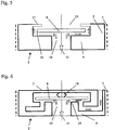
- Fig. 7
- shows a principal sketch of a fourth embodiment of the control device according to WO 2008 004 875.
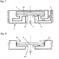
- Fig. 8
- shows a principal sketch of a fifth embodiment of WO 2008 004 875 where the control device is an integral part of a flow arrangement.
- Fig. 9
- shows a typical injection profile in a reservoir with fractures and conventional technology.
- Fig. 10
- shows a typical injection profile in a reservoir with fractures and the method according to the present invention.
-
Fig. 1 shows, as stated above, a section of aproduction pipe 1 in which a prototype of acontrol device 2, according to WO 2008 004 875 is provided. Thecontrol device 2 is preferably of circular, relatively flat shape and may be provided with external threads 3 (seeFig. 2 ) to be screwed into a circular hole with corresponding internal threads in the pipe or an injector. By controlling the thickness, thedevice 2, may be adapted to the thickness of the pipe or injector and fit within its outer and inner periphery. -
Fig. 2 a) and b) shows theprior control device 2 of WO 2008 004 875 in larger scale. The device consists of a first disc-shaped housing body 4 with an outercylindrical segment 5 and innercylindrical segment 6 and with a central hole oraperture 10, and a second disc-shaped holder body 7 with an outercylindrical segment 8, as well as a preferably flat disc or freely movable body 9 provided in anopen space 14 formed between the first 4 and second 7 disc-shaped housing and holder bodies. The body 9 may for particular applications and adjustments depart from the flat shape and have a partly conical or semicircular shape (for instance towards theaperture 10.) As can be seen from the figure, thecylindrical segment 8 of the second disc-shaped holder body 7 fits within and protrudes in the opposite direction of the outercylindrical segment 5 of the first disc-shaped housing body 4 thereby forming a flow path as shown by thearrows 11, where the fluid enters the control device through the central hole or aperture (inlet) 10 and flows towards and radially along the disc 9 before flowing through theannular opening 12 formed between thecylindrical segments annular opening 13 formed between thecylindrical segments holder bodies connection area 15 as shown inFig 2b ). - The present invention exploits the effect of Bernoulli teaching that the sum of static pressure, dynamic pressure and friction is constant along a flow line:

- When subjecting the disc 9 to a fluid flow, which is the case with the present invention, the pressure difference over the disc 9 can be expressed as follows:

- Due to lower viscosity, a fluid such as gas will "make the turn later" and follow further along the disc towards its outer end (indicated by reference number 14). This makes a higher stagnation pressure in the
area 16 at the end of the disc 9, which in turn makes a higher pressure over the disc. And the disc 9, which is freely movable within the space between the disc-shapedbodies cylindrical segment 6. Thus, the disc 9 moves dawn-wards or up-wards depending on the viscosity of the fluid flowing through, whereby this principle can be used to control (close/open) the flow of fluid through of the device. - Further, the pressure drop through a traditional inflow control device (ICD) with fixed geometry will be proportional to the dynamic pressure:

Fig. 3 , and as can be seen from the figure, the flow-through volume for the present invention is constant above a given differential pressure. - This represents a major advantage with the present invention as it can be used to ensure the same volume flowing through each section for the entire horizontal well, which is not possible with fixed inflow control devices.
- When producing oil and gas the control device according to the invention may have two different applications: Using it as inflow control device to reduce inflow of water, or using it to reduce inflow of gas at gas break through situations. When designing the control device according to the invention for the different application such as water or gas, as mentioned above, the different areas and pressure zones, as shown in
Fig. 4 , will have impact on the efficiency and flow through properties of the device. Referring toFig. 4 , the different area/pressure zones may be divided into: - A1, P1 is the inflow area and pressure respectively. The force (P1·A1) generated by this pressure will strive to open the control device (move the disc or body 9 upwards).
- A2, P2 is the area and pressure in the zone where the velocity will be largest and hence represents a dynamic pressure source. The resulting force of the dynamic pressure will strive to close the control device (move the disc or body 9 downwards as the flow velocity increases).
- A3, P3 is the area and pressure at the outlet. This should be the same as the well pressure (inlet pressure).
- A4, P4 is the area and pressure (stagnation pressure) behind the movable disc or body 9. The stagnation pressure, at position 16 (
Fig. 2 ), creates the pressure and the force behind the body. This will strive to close the control device (move the body downwards). - Fluids with different viscosities will provide different forces in each zone depending on the design of these zones. In order to optimize the efficiency and flow through properties of the control device, the design of the areas will be different for different applications, e.g. gas/oil or oil/water flow. Hence, for each application the areas needs to be carefully balanced and optimally designed taking into account the properties and physical conditions (viscosity, temperature, pressure etc.) for each design situation.
-
Fig. 5 shows a principal sketch of another embodiment of the control device according to WO 2008 004 875, which is of a more simple design than the version shown inFig. 2 . Thecontrol device 2 consists, as with the version shown inFig. 2 , of a first disc-shapedhousing body 4 with an outercylindrical segment 5 and with a central hole oraperture 10, and a second disc-shapedholder body 17 attached to thesegment 5 of thehousing body 4, as well as a preferably flat disc 9 provided in anopen space 14 formed between the first and second disc-shaped housing andholder bodies holder body 17 is inwardly open (through a hole or holes 23, etc.) and is now only holding the disc in place, and since thecylindrical segment 5 is shorter with a different flow path than what is shown inFig.2 , there is no build up of stagnation pressure (P4) on the back side of the disc 9 as explained above in conjunction withFig. 4 . With this solution without stagnation pressure the building thickness for the device is lower and may withstand a larger amount of particles contained in the fluid. -
Fig. 6 shows a third embodiment according to WO 2008 004 875 where the design is the same as with the example shown inFig. 2 , but where aspring element 18, in the form of a spiral or other suitable spring device, is provided on either side of the disc and connects the disc with theholder recess 21 orhousing 4. - The
spring element 18 is used to balance and control the inflow area between the disc 9 and theinlet 10, or rather the surrounding edge orseat 19 of theinlet 10. Thus, depending on the spring constant and thereby the spring force, the opening between the disc 9 and edge 19 will be larger or smaller, and with a suitable selected spring constant, depending on the inflow and pressure conditions at the selected place where the control device is provided, constant mass flow through the device may be obtained. -
Fig. 7 shows a fourth embodiment according to WO 2008 004 875, where the design is the same as with the example inFig. 6 above, but where the disc 9 is, on the side facing theinlet opening 10, provided with a thermally responsive device such asbi-metallic element 20. - When producing oil and/or gas the conditions may rapidly change from a situation where only or mostly oil is produced to a situation where only or mostly gas is produced (gas breakt-hrough or gas coning). With for instance a pressure drop of 16 bar from 100 bar the temperature drop would correspond to approximately 20 °C. By providing the disc 9 with a thermally responsive element such as a bi-metallic element as shown in
Fig. 7 , the disc will bend upwards or be moved upwards by theelement 20 abutting the holder shapedbody 7 and thereby narrowing the opening between the disc and theinlet 10 or fully closing said inlet. - The above examples of a control device as shown in
Figs. 1 and2 and4 - 7 are all related to solutions where the control device as such is a separate unit or device to be provided in conjunction with a fluid flow situation or arrangement such as the wall of a production pipe in connection with the production of oil and gas. However, the control device may, as shown inFig. 8 , be an integral part of the fluid flow arrangement, whereby the movable body 9 may be provided in arecess 21 facing the outlet of an aperture orhole 10 of for instance a wall of apipe 1 as shown inFig. 1 instead of being provided in aseparate housing body 4. Further, the movable body 9 may be held in place in the recess by means of a holder device such as inwardly protruding spikes, acircular ring 22 or the like being connected to the outer opening of the recess by means of screwing, welding or the like. -
Figs. 9 and 10 show typical injection profiles in a reservoir with fractures F, using conventional technologi and the method according to the present invention, respectively. Infigure 10 a plurality of autonomous valves or control devices 2 (not shown in the figure) are provided along the length of aninjector 24, leading to a substantially uniform injection of the fluid as shown with the line of arrows (UIF) of almost equal length. Contrary, the conventional injection technology shown infig. 9 leads to a non-uniform injection of fluid (NIF), especially in the fractures F in which the injected fluid makes a shortcut, as also mentioned in the introductionary part of the description. In bothfig. 9 and 10 theproduction pipe 1 is the same, and the flow directions in theproduction pipe 1 and in theinjector 24 are indicated witharrows figures 9 and 10 , two lines indicating gas-oil contact (GOC) and water-oil contact (WOC) are further shown. - With the present invention, due to the constant volume rate, a much better drainage of the reservoir is thus achieved. This result in significant larger production of that reservoir. At the same time the required amount of injected fluids can be reduced significantly. This is important e.g. in bitumen production where steam is injected.
- Further, due to the flow characteristic of the valve, the injection along the different section of the well will be substantially uniform. This is ensured by the unique constant volume rate of the
valve 2, even for non-uniform reservoir where the pressure drop in it will vary. - As fluids for injection a.o. water, steam, hydrocarbon gas and/or CO2 might be used, and other fluids are also conceivable within the scope of the present invention as defined by the appended claims.
Claims (3)
- A method for injecting a fluid into an oil and or gas reservoir or formation,
characterised in that
the fluid flows into the reservoir or formation through a plurality of autonomous valves or flow control devices (2) provided along an injector, the valves (2) having a substantially constant flow-through volume above a given differential pressure for autonomously adjusting the flow of the fluid in order to ensure a substantially constant volume rate from the injector to the reservoir or formation along an injector length. - A method according to claim 1,
characterised by
including a freely movable controlling body (9) being provided in a recess (21) of the injector (24) wall or being provided in a separate housing body (4) in the wall, the controlling body (9) facing the outlet of an aperture or hole (10) in the centre of the recess (21) or housing body (4) and being held in place in the recess (21) or housing body (4) by means of a holder device or arrangement (7, 22), thereby forming a flow path (11) where the fluid enters the control device through the central aperture or inlet (10') flowing towards and along the body (9) and out of the recess or housing. - A method in accordance with claims 1 and 2,
characterised in that
the fluid is water, steam, hydrocarbon gas and/or CO2.
Applications Claiming Priority (2)
| Application Number | Priority Date | Filing Date | Title |
|---|---|---|---|
| NO20080081A NO20080081L (en) | 2008-01-04 | 2008-01-04 | Method for autonomously adjusting a fluid flow through a valve or flow control device in injectors in oil production |
| PCT/NO2008/000455 WO2009088293A1 (en) | 2008-01-04 | 2008-12-16 | Method for self-adjusting (autonomously adjusting) the flow of a fluid through a valve or flow control device in injectors in oil production |
Publications (2)
| Publication Number | Publication Date |
|---|---|
| EP2245268A1 EP2245268A1 (en) | 2010-11-03 |
| EP2245268B1 true EP2245268B1 (en) | 2012-04-18 |
Family
ID=40565071
Family Applications (1)
| Application Number | Title | Priority Date | Filing Date |
|---|---|---|---|
| EP20080870295 Active EP2245268B1 (en) | 2008-01-04 | 2008-12-16 | Method for self-adjusting (autonomously adjusting) the flow of a fluid through a valve or flow control device in injectors in oil production |
Country Status (14)
| Country | Link |
|---|---|
| US (1) | US8485258B2 (en) |
| EP (1) | EP2245268B1 (en) |
| CN (1) | CN101939506B (en) |
| AT (1) | ATE554268T1 (en) |
| AU (1) | AU2008345749B2 (en) |
| BR (1) | BRPI0821932B1 (en) |
| CA (1) | CA2711371C (en) |
| DK (1) | DK2245268T3 (en) |
| EA (1) | EA016671B1 (en) |
| EG (1) | EG26582A (en) |
| MX (1) | MX2010007362A (en) |
| MY (1) | MY152045A (en) |
| NO (1) | NO20080081L (en) |
| WO (1) | WO2009088293A1 (en) |
Families Citing this family (43)
| Publication number | Priority date | Publication date | Assignee | Title |
|---|---|---|---|---|
| AU2008305337B2 (en) | 2007-09-25 | 2014-11-13 | Schlumberger Technology B.V. | Flow control systems and methods |
| NO20080082L (en) * | 2008-01-04 | 2009-07-06 | Statoilhydro Asa | Improved flow control method and autonomous valve or flow control device |
| NO20081078L (en) * | 2008-02-29 | 2009-08-31 | Statoilhydro Asa | Pipe element with self-regulating valves for controlling the flow of fluid into or out of the pipe element |
| US8893804B2 (en) | 2009-08-18 | 2014-11-25 | Halliburton Energy Services, Inc. | Alternating flow resistance increases and decreases for propagating pressure pulses in a subterranean well |
| US8235128B2 (en) | 2009-08-18 | 2012-08-07 | Halliburton Energy Services, Inc. | Flow path control based on fluid characteristics to thereby variably resist flow in a subterranean well |
| US9109423B2 (en) | 2009-08-18 | 2015-08-18 | Halliburton Energy Services, Inc. | Apparatus for autonomous downhole fluid selection with pathway dependent resistance system |
| US8276669B2 (en) | 2010-06-02 | 2012-10-02 | Halliburton Energy Services, Inc. | Variable flow resistance system with circulation inducing structure therein to variably resist flow in a subterranean well |
| US8291976B2 (en) | 2009-12-10 | 2012-10-23 | Halliburton Energy Services, Inc. | Fluid flow control device |
| US8708050B2 (en) | 2010-04-29 | 2014-04-29 | Halliburton Energy Services, Inc. | Method and apparatus for controlling fluid flow using movable flow diverter assembly |
| US8261839B2 (en) | 2010-06-02 | 2012-09-11 | Halliburton Energy Services, Inc. | Variable flow resistance system for use in a subterranean well |
| NO338616B1 (en) * | 2010-08-04 | 2016-09-12 | Statoil Petroleum As | Apparatus and method for storing carbon dioxide in underground geological formations |
| US8356668B2 (en) | 2010-08-27 | 2013-01-22 | Halliburton Energy Services, Inc. | Variable flow restrictor for use in a subterranean well |
| US8430130B2 (en) | 2010-09-10 | 2013-04-30 | Halliburton Energy Services, Inc. | Series configured variable flow restrictors for use in a subterranean well |
| US8950502B2 (en) | 2010-09-10 | 2015-02-10 | Halliburton Energy Services, Inc. | Series configured variable flow restrictors for use in a subterranean well |
| US8851180B2 (en) | 2010-09-14 | 2014-10-07 | Halliburton Energy Services, Inc. | Self-releasing plug for use in a subterranean well |
| US8733401B2 (en) | 2010-12-31 | 2014-05-27 | Halliburton Energy Services, Inc. | Cone and plate fluidic oscillator inserts for use with a subterranean well |
| US8418725B2 (en) | 2010-12-31 | 2013-04-16 | Halliburton Energy Services, Inc. | Fluidic oscillators for use with a subterranean well |
| US8646483B2 (en) | 2010-12-31 | 2014-02-11 | Halliburton Energy Services, Inc. | Cross-flow fluidic oscillators for use with a subterranean well |
| CN103443394B (en) * | 2011-01-14 | 2016-10-19 | 斯塔特伊石油公司 | Autonomous valve |
| CA2828689C (en) | 2011-04-08 | 2016-12-06 | Halliburton Energy Services, Inc. | Method and apparatus for controlling fluid flow in an autonomous valve using a sticky switch |
| US8678035B2 (en) | 2011-04-11 | 2014-03-25 | Halliburton Energy Services, Inc. | Selectively variable flow restrictor for use in a subterranean well |
| US8844651B2 (en) | 2011-07-21 | 2014-09-30 | Halliburton Energy Services, Inc. | Three dimensional fluidic jet control |
| US8863835B2 (en) | 2011-08-23 | 2014-10-21 | Halliburton Energy Services, Inc. | Variable frequency fluid oscillators for use with a subterranean well |
| US8955585B2 (en) | 2011-09-27 | 2015-02-17 | Halliburton Energy Services, Inc. | Forming inclusions in selected azimuthal orientations from a casing section |
| CA2848963C (en) | 2011-10-31 | 2015-06-02 | Halliburton Energy Services, Inc | Autonomous fluid control device having a movable valve plate for downhole fluid selection |
| AU2011380521B2 (en) | 2011-10-31 | 2016-09-22 | Halliburton Energy Services, Inc. | Autonomous fluid control device having a reciprocating valve for downhole fluid selection |
| US9506320B2 (en) | 2011-11-07 | 2016-11-29 | Halliburton Energy Services, Inc. | Variable flow resistance for use with a subterranean well |
| US8739880B2 (en) | 2011-11-07 | 2014-06-03 | Halliburton Energy Services, P.C. | Fluid discrimination for use with a subterranean well |
| US8684094B2 (en) | 2011-11-14 | 2014-04-01 | Halliburton Energy Services, Inc. | Preventing flow of undesired fluid through a variable flow resistance system in a well |
| US20140054050A1 (en) * | 2012-08-24 | 2014-02-27 | Halliburton Energy Services, Inc. | Gas Fracture Injection to Overcome Retrograde Condensation in Gas Wells |
| US9404349B2 (en) | 2012-10-22 | 2016-08-02 | Halliburton Energy Services, Inc. | Autonomous fluid control system having a fluid diode |
| US9127526B2 (en) | 2012-12-03 | 2015-09-08 | Halliburton Energy Services, Inc. | Fast pressure protection system and method |
| US9695654B2 (en) | 2012-12-03 | 2017-07-04 | Halliburton Energy Services, Inc. | Wellhead flowback control system and method |
| CA2918808A1 (en) | 2013-07-31 | 2015-02-05 | Schlumberger Canada Limited | Sand control system and methodology |
| CA2914366C (en) | 2013-08-01 | 2017-12-12 | Landmark Graphics Corporation | Algorithm for optimal icd configuration using a coupled wellbore-reservoir model |
| GB201418062D0 (en) * | 2014-10-13 | 2014-11-26 | Flotech Holdings Bvi Ltd | Downhole flow control device |
| US10871057B2 (en) | 2015-06-30 | 2020-12-22 | Schlumberger Technology Corporation | Flow control device for a well |
| GB2557063B (en) | 2015-08-13 | 2021-08-04 | Packers Plus Energy Serv Inc | Inflow control device for wellbore operations |
| CN105089543B (en) * | 2015-09-02 | 2017-09-01 | 中国石油天然气股份有限公司 | A kind of horizontal well pressure water control device |
| CN106089150A (en) * | 2016-07-18 | 2016-11-09 | 西安石油大学 | A kind of adaptive layered water filling adjusting control valve |
| GB2559343B (en) * | 2017-01-31 | 2020-06-24 | Swellfix Uk Ltd | Downhole flow control device and method. |
| US11613963B2 (en) * | 2017-07-24 | 2023-03-28 | Halliburton Energy Services, Inc. | Flow control system for a non-newtonian fluid in a subterranean well |
| US11066909B2 (en) | 2019-11-27 | 2021-07-20 | Halliburton Energy Services, Inc. | Mechanical isolation plugs for inflow control devices |
Family Cites Families (19)
| Publication number | Priority date | Publication date | Assignee | Title |
|---|---|---|---|---|
| US3381708A (en) * | 1965-09-07 | 1968-05-07 | Baker Oil Tools Inc | Fluid flow regulator |
| US3381749A (en) * | 1965-09-07 | 1968-05-07 | Baker Oil Tools Inc | Multiple injection packers |
| US3319717A (en) * | 1965-10-04 | 1967-05-16 | Baker Oil Tools Inc | Multiple zone injection apparatus for well bores |
| US4577691A (en) | 1984-09-10 | 1986-03-25 | Texaco Inc. | Method and apparatus for producing viscous hydrocarbons from a subterranean formation |
| CA1247000A (en) | 1984-12-31 | 1988-12-20 | Texaco Canada Resources Ltd. | Method and apparatus for producing viscous hydrocarbons utilizing a hot stimulating medium |
| CA1275914C (en) | 1986-06-30 | 1990-11-06 | Hermanus Geert Van Laar | Producing asphaltic crude oil |
| US4791956A (en) | 1987-09-28 | 1988-12-20 | Asahi Yukizai Kogyo Co., Ltd. | Constant flow valve |
| US4858691A (en) | 1988-06-13 | 1989-08-22 | Baker Hughes Incorporated | Gravel packing apparatus and method |
| US4858644A (en) * | 1988-05-31 | 1989-08-22 | Otis Engineering Corporation | Fluid flow regulator |
| EP0491684B1 (en) * | 1989-09-11 | 1997-08-13 | PALMER, David W. | Flow control system |
| US4986352A (en) * | 1989-09-28 | 1991-01-22 | Mobil Oil Corporation | Intermittent steam injection |
| GB9025230D0 (en) | 1990-11-20 | 1991-01-02 | Framo Dev Ltd | Well completion system |
| NO306127B1 (en) | 1992-09-18 | 1999-09-20 | Norsk Hydro As | Process and production piping for the production of oil or gas from an oil or gas reservoir |
| MY134072A (en) * | 2001-02-19 | 2007-11-30 | Shell Int Research | Method for controlling fluid into an oil and/or gas production well |
| GB2376488B (en) | 2001-06-12 | 2004-05-12 | Schlumberger Holdings | Flow control regulation method and apparatus |
| US7537056B2 (en) * | 2004-12-21 | 2009-05-26 | Schlumberger Technology Corporation | System and method for gas shut off in a subterranean well |
| MY163991A (en) | 2006-07-07 | 2017-11-15 | Statoil Petroleum As | Method for flow control and autonomous valve or flow control device |
| WO2008022048A2 (en) * | 2006-08-10 | 2008-02-21 | California Institute Of Technology | Microfluidic valve having free-floating member and method of fabrication |
| US8261822B2 (en) * | 2008-10-21 | 2012-09-11 | Baker Hughes Incorporated | Flow regulator assembly |
-
2008
- 2008-01-04 NO NO20080081A patent/NO20080081L/en unknown
- 2008-12-16 AT AT08870295T patent/ATE554268T1/en active
- 2008-12-16 US US12/811,425 patent/US8485258B2/en active Active
- 2008-12-16 CN CN200880126376.XA patent/CN101939506B/en active Active
- 2008-12-16 BR BRPI0821932A patent/BRPI0821932B1/en active IP Right Grant
- 2008-12-16 CA CA2711371A patent/CA2711371C/en active Active
- 2008-12-16 AU AU2008345749A patent/AU2008345749B2/en active Active
- 2008-12-16 WO PCT/NO2008/000455 patent/WO2009088293A1/en active Application Filing
- 2008-12-16 MY MYPI2010003146A patent/MY152045A/en unknown
- 2008-12-16 DK DK08870295T patent/DK2245268T3/en active
- 2008-12-16 EP EP20080870295 patent/EP2245268B1/en active Active
- 2008-12-16 EA EA201070825A patent/EA016671B1/en not_active IP Right Cessation
- 2008-12-16 MX MX2010007362A patent/MX2010007362A/en active IP Right Grant
-
2010
- 2010-07-01 EG EG2010071135A patent/EG26582A/en active
Also Published As
| Publication number | Publication date |
|---|---|
| EG26582A (en) | 2014-03-17 |
| NO20080081L (en) | 2009-07-06 |
| EA201070825A1 (en) | 2010-12-30 |
| ATE554268T1 (en) | 2012-05-15 |
| CN101939506A (en) | 2011-01-05 |
| BRPI0821932A2 (en) | 2015-06-16 |
| DK2245268T3 (en) | 2012-07-23 |
| MX2010007362A (en) | 2010-10-25 |
| EP2245268A1 (en) | 2010-11-03 |
| MY152045A (en) | 2014-08-15 |
| CA2711371C (en) | 2016-04-12 |
| AU2008345749A1 (en) | 2009-07-16 |
| BRPI0821932B1 (en) | 2018-12-04 |
| US8485258B2 (en) | 2013-07-16 |
| AU2008345749B2 (en) | 2014-05-15 |
| WO2009088293A1 (en) | 2009-07-16 |
| EA016671B1 (en) | 2012-06-29 |
| US20110011590A1 (en) | 2011-01-20 |
| CA2711371A1 (en) | 2009-07-16 |
| CN101939506B (en) | 2014-07-23 |
Similar Documents
| Publication | Publication Date | Title |
|---|---|---|
| EP2245268B1 (en) | Method for self-adjusting (autonomously adjusting) the flow of a fluid through a valve or flow control device in injectors in oil production | |
| EP2049766B1 (en) | Method for flow control and autonomous valve or flow control device | |
| US8820413B2 (en) | Alternative design of self-adjusting valve | |
| US8590630B2 (en) | System and method for controlling the flow of fluid in branched wells | |
| EP2531692B1 (en) | Flow control device and flow control method | |
| US8517099B2 (en) | Tubular member having self-adjusting valves controlling the flow of fluid into or out of the tubular member | |
| US20110056700A1 (en) | System and method for recompletion of old wells |
Legal Events
| Date | Code | Title | Description |
|---|---|---|---|
| PUAI | Public reference made under article 153(3) epc to a published international application that has entered the european phase |
Free format text: ORIGINAL CODE: 0009012 |
|
| 17P | Request for examination filed |
Effective date: 20100802 |
|
| AK | Designated contracting states |
Kind code of ref document: A1 Designated state(s): AT BE BG CH CY CZ DE DK EE ES FI FR GB GR HR HU IE IS IT LI LT LU LV MC MT NL NO PL PT RO SE SI SK TR |
|
| AX | Request for extension of the european patent |
Extension state: AL BA MK RS |
|
| DAX | Request for extension of the european patent (deleted) | ||
| GRAP | Despatch of communication of intention to grant a patent |
Free format text: ORIGINAL CODE: EPIDOSNIGR1 |
|
| GRAS | Grant fee paid |
Free format text: ORIGINAL CODE: EPIDOSNIGR3 |
|
| GRAA | (expected) grant |
Free format text: ORIGINAL CODE: 0009210 |
|
| AK | Designated contracting states |
Kind code of ref document: B1 Designated state(s): AT BE BG CH CY CZ DE DK EE ES FI FR GB GR HR HU IE IS IT LI LT LU LV MC MT NL NO PL PT RO SE SI SK TR |
|
| REG | Reference to a national code |
Ref country code: GB Ref legal event code: FG4D |
|
| REG | Reference to a national code |
Ref country code: CH Ref legal event code: EP |
|
| REG | Reference to a national code |
Ref country code: IE Ref legal event code: FG4D |
|
| REG | Reference to a national code |
Ref country code: AT Ref legal event code: REF Ref document number: 554268 Country of ref document: AT Kind code of ref document: T Effective date: 20120515 |
|
| REG | Reference to a national code |
Ref country code: DE Ref legal event code: R096 Ref document number: 602008015097 Country of ref document: DE Effective date: 20120614 |
|
| REG | Reference to a national code |
Ref country code: NL Ref legal event code: T3 |
|
| REG | Reference to a national code |
Ref country code: DK Ref legal event code: T3 |
|
| REG | Reference to a national code |
Ref country code: NO Ref legal event code: T2 Effective date: 20120418 |
|
| REG | Reference to a national code |
Ref country code: AT Ref legal event code: MK05 Ref document number: 554268 Country of ref document: AT Kind code of ref document: T Effective date: 20120418 |
|
| LTIE | Lt: invalidation of european patent or patent extension |
Effective date: 20120418 |
|
| PG25 | Lapsed in a contracting state [announced via postgrant information from national office to epo] |
Ref country code: CY Free format text: LAPSE BECAUSE OF FAILURE TO SUBMIT A TRANSLATION OF THE DESCRIPTION OR TO PAY THE FEE WITHIN THE PRESCRIBED TIME-LIMIT Effective date: 20120418 Ref country code: IS Free format text: LAPSE BECAUSE OF FAILURE TO SUBMIT A TRANSLATION OF THE DESCRIPTION OR TO PAY THE FEE WITHIN THE PRESCRIBED TIME-LIMIT Effective date: 20120818 Ref country code: PL Free format text: LAPSE BECAUSE OF FAILURE TO SUBMIT A TRANSLATION OF THE DESCRIPTION OR TO PAY THE FEE WITHIN THE PRESCRIBED TIME-LIMIT Effective date: 20120418 Ref country code: LT Free format text: LAPSE BECAUSE OF FAILURE TO SUBMIT A TRANSLATION OF THE DESCRIPTION OR TO PAY THE FEE WITHIN THE PRESCRIBED TIME-LIMIT Effective date: 20120418 Ref country code: FI Free format text: LAPSE BECAUSE OF FAILURE TO SUBMIT A TRANSLATION OF THE DESCRIPTION OR TO PAY THE FEE WITHIN THE PRESCRIBED TIME-LIMIT Effective date: 20120418 Ref country code: SE Free format text: LAPSE BECAUSE OF FAILURE TO SUBMIT A TRANSLATION OF THE DESCRIPTION OR TO PAY THE FEE WITHIN THE PRESCRIBED TIME-LIMIT Effective date: 20120418 |
|
| PG25 | Lapsed in a contracting state [announced via postgrant information from national office to epo] |
Ref country code: PT Free format text: LAPSE BECAUSE OF FAILURE TO SUBMIT A TRANSLATION OF THE DESCRIPTION OR TO PAY THE FEE WITHIN THE PRESCRIBED TIME-LIMIT Effective date: 20120820 Ref country code: LV Free format text: LAPSE BECAUSE OF FAILURE TO SUBMIT A TRANSLATION OF THE DESCRIPTION OR TO PAY THE FEE WITHIN THE PRESCRIBED TIME-LIMIT Effective date: 20120418 Ref country code: GR Free format text: LAPSE BECAUSE OF FAILURE TO SUBMIT A TRANSLATION OF THE DESCRIPTION OR TO PAY THE FEE WITHIN THE PRESCRIBED TIME-LIMIT Effective date: 20120719 Ref country code: SI Free format text: LAPSE BECAUSE OF FAILURE TO SUBMIT A TRANSLATION OF THE DESCRIPTION OR TO PAY THE FEE WITHIN THE PRESCRIBED TIME-LIMIT Effective date: 20120418 Ref country code: HR Free format text: LAPSE BECAUSE OF FAILURE TO SUBMIT A TRANSLATION OF THE DESCRIPTION OR TO PAY THE FEE WITHIN THE PRESCRIBED TIME-LIMIT Effective date: 20120418 |
|
| PG25 | Lapsed in a contracting state [announced via postgrant information from national office to epo] |
Ref country code: BE Free format text: LAPSE BECAUSE OF FAILURE TO SUBMIT A TRANSLATION OF THE DESCRIPTION OR TO PAY THE FEE WITHIN THE PRESCRIBED TIME-LIMIT Effective date: 20120418 |
|
| PG25 | Lapsed in a contracting state [announced via postgrant information from national office to epo] |
Ref country code: CZ Free format text: LAPSE BECAUSE OF FAILURE TO SUBMIT A TRANSLATION OF THE DESCRIPTION OR TO PAY THE FEE WITHIN THE PRESCRIBED TIME-LIMIT Effective date: 20120418 Ref country code: SK Free format text: LAPSE BECAUSE OF FAILURE TO SUBMIT A TRANSLATION OF THE DESCRIPTION OR TO PAY THE FEE WITHIN THE PRESCRIBED TIME-LIMIT Effective date: 20120418 Ref country code: RO Free format text: LAPSE BECAUSE OF FAILURE TO SUBMIT A TRANSLATION OF THE DESCRIPTION OR TO PAY THE FEE WITHIN THE PRESCRIBED TIME-LIMIT Effective date: 20120418 Ref country code: EE Free format text: LAPSE BECAUSE OF FAILURE TO SUBMIT A TRANSLATION OF THE DESCRIPTION OR TO PAY THE FEE WITHIN THE PRESCRIBED TIME-LIMIT Effective date: 20120418 Ref country code: AT Free format text: LAPSE BECAUSE OF FAILURE TO SUBMIT A TRANSLATION OF THE DESCRIPTION OR TO PAY THE FEE WITHIN THE PRESCRIBED TIME-LIMIT Effective date: 20120418 |
|
| PLBE | No opposition filed within time limit |
Free format text: ORIGINAL CODE: 0009261 |
|
| STAA | Information on the status of an ep patent application or granted ep patent |
Free format text: STATUS: NO OPPOSITION FILED WITHIN TIME LIMIT |
|
| PG25 | Lapsed in a contracting state [announced via postgrant information from national office to epo] |
Ref country code: IT Free format text: LAPSE BECAUSE OF FAILURE TO SUBMIT A TRANSLATION OF THE DESCRIPTION OR TO PAY THE FEE WITHIN THE PRESCRIBED TIME-LIMIT Effective date: 20120418 |
|
| 26N | No opposition filed |
Effective date: 20130121 |
|
| PG25 | Lapsed in a contracting state [announced via postgrant information from national office to epo] |
Ref country code: ES Free format text: LAPSE BECAUSE OF FAILURE TO SUBMIT A TRANSLATION OF THE DESCRIPTION OR TO PAY THE FEE WITHIN THE PRESCRIBED TIME-LIMIT Effective date: 20120729 |
|
| REG | Reference to a national code |
Ref country code: DE Ref legal event code: R097 Ref document number: 602008015097 Country of ref document: DE Effective date: 20130121 |
|
| PG25 | Lapsed in a contracting state [announced via postgrant information from national office to epo] |
Ref country code: MC Free format text: LAPSE BECAUSE OF NON-PAYMENT OF DUE FEES Effective date: 20121231 Ref country code: BG Free format text: LAPSE BECAUSE OF FAILURE TO SUBMIT A TRANSLATION OF THE DESCRIPTION OR TO PAY THE FEE WITHIN THE PRESCRIBED TIME-LIMIT Effective date: 20120718 |
|
| REG | Reference to a national code |
Ref country code: CH Ref legal event code: PL |
|
| REG | Reference to a national code |
Ref country code: IE Ref legal event code: MM4A |
|
| REG | Reference to a national code |
Ref country code: FR Ref legal event code: ST Effective date: 20130830 |
|
| REG | Reference to a national code |
Ref country code: GB Ref legal event code: 732E Free format text: REGISTERED BETWEEN 20130905 AND 20130911 |
|
| REG | Reference to a national code |
Ref country code: DE Ref legal event code: R082 Ref document number: 602008015097 Country of ref document: DE Representative=s name: MARKS & CLERK (LUXEMBOURG) LLP, LU |
|
| REG | Reference to a national code |
Ref country code: DE Ref legal event code: R082 Ref document number: 602008015097 Country of ref document: DE Representative=s name: MARKS & CLERK (LUXEMBOURG) LLP, LU |
|
| PG25 | Lapsed in a contracting state [announced via postgrant information from national office to epo] |
Ref country code: CH Free format text: LAPSE BECAUSE OF NON-PAYMENT OF DUE FEES Effective date: 20121231 Ref country code: LI Free format text: LAPSE BECAUSE OF NON-PAYMENT OF DUE FEES Effective date: 20121231 Ref country code: IE Free format text: LAPSE BECAUSE OF NON-PAYMENT OF DUE FEES Effective date: 20121216 |
|
| PG25 | Lapsed in a contracting state [announced via postgrant information from national office to epo] |
Ref country code: FR Free format text: LAPSE BECAUSE OF NON-PAYMENT OF DUE FEES Effective date: 20130102 Ref country code: MT Free format text: LAPSE BECAUSE OF FAILURE TO SUBMIT A TRANSLATION OF THE DESCRIPTION OR TO PAY THE FEE WITHIN THE PRESCRIBED TIME-LIMIT Effective date: 20120418 |
|
| REG | Reference to a national code |
Ref country code: DE Ref legal event code: R082 Ref document number: 602008015097 Country of ref document: DE Representative=s name: MARKS & CLERK (LUXEMBOURG) LLP, LU Effective date: 20131017 Ref country code: DE Ref legal event code: R081 Ref document number: 602008015097 Country of ref document: DE Owner name: STATOIL PETROLEUM AS, NO Free format text: FORMER OWNER: STATOIL ASA, STAVANGER, NO Effective date: 20131021 Ref country code: DE Ref legal event code: R082 Ref document number: 602008015097 Country of ref document: DE Representative=s name: MARKS & CLERK (LUXEMBOURG) LLP, LU Effective date: 20131021 Ref country code: DE Ref legal event code: R081 Ref document number: 602008015097 Country of ref document: DE Owner name: STATOIL PETROLEUM AS, NO Free format text: FORMER OWNER: STATOIL ASA, STAVANGER, NO Effective date: 20131017 Ref country code: DE Ref legal event code: R081 Ref document number: 602008015097 Country of ref document: DE Owner name: STATOIL PETROLEUM AS, NO Free format text: FORMER OWNER: STATOIL HYDRO ASA, STAVANGER, NO Effective date: 20131021 |
|
| REG | Reference to a national code |
Ref country code: NL Ref legal event code: SD Effective date: 20131220 Ref country code: NL Ref legal event code: TD Effective date: 20131220 |
|
| PGFP | Annual fee paid to national office [announced via postgrant information from national office to epo] |
Ref country code: NL Payment date: 20131219 Year of fee payment: 6 |
|
| PG25 | Lapsed in a contracting state [announced via postgrant information from national office to epo] |
Ref country code: TR Free format text: LAPSE BECAUSE OF FAILURE TO SUBMIT A TRANSLATION OF THE DESCRIPTION OR TO PAY THE FEE WITHIN THE PRESCRIBED TIME-LIMIT Effective date: 20120418 |
|
| REG | Reference to a national code |
Ref country code: NO Ref legal event code: CHAD Owner name: STATOIL ASA, NO |
|
| PG25 | Lapsed in a contracting state [announced via postgrant information from national office to epo] |
Ref country code: LU Free format text: LAPSE BECAUSE OF NON-PAYMENT OF DUE FEES Effective date: 20121216 |
|
| PG25 | Lapsed in a contracting state [announced via postgrant information from national office to epo] |
Ref country code: HU Free format text: LAPSE BECAUSE OF FAILURE TO SUBMIT A TRANSLATION OF THE DESCRIPTION OR TO PAY THE FEE WITHIN THE PRESCRIBED TIME-LIMIT Effective date: 20081216 |
|
| REG | Reference to a national code |
Ref country code: NO Ref legal event code: CHAD Owner name: STATOIL PETROLEUM AS, NO |
|
| REG | Reference to a national code |
Ref country code: NL Ref legal event code: V1 Effective date: 20150701 |
|
| REG | Reference to a national code |
Ref country code: NL Ref legal event code: V1 Effective date: 20150701 |
|
| PG25 | Lapsed in a contracting state [announced via postgrant information from national office to epo] |
Ref country code: NL Free format text: LAPSE BECAUSE OF NON-PAYMENT OF DUE FEES Effective date: 20150701 |
|
| PGFP | Annual fee paid to national office [announced via postgrant information from national office to epo] |
Ref country code: DK Payment date: 20201222 Year of fee payment: 13 |
|
| PGFP | Annual fee paid to national office [announced via postgrant information from national office to epo] |
Ref country code: DE Payment date: 20210224 Year of fee payment: 13 |
|
| REG | Reference to a national code |
Ref country code: DE Ref legal event code: R119 Ref document number: 602008015097 Country of ref document: DE |
|
| REG | Reference to a national code |
Ref country code: DK Ref legal event code: EBP Effective date: 20211231 |
|
| PG25 | Lapsed in a contracting state [announced via postgrant information from national office to epo] |
Ref country code: DE Free format text: LAPSE BECAUSE OF NON-PAYMENT OF DUE FEES Effective date: 20220701 |
|
| PG25 | Lapsed in a contracting state [announced via postgrant information from national office to epo] |
Ref country code: DK Free format text: LAPSE BECAUSE OF NON-PAYMENT OF DUE FEES Effective date: 20211231 |
|
| P01 | Opt-out of the competence of the unified patent court (upc) registered |
Effective date: 20230525 |
|
| PGFP | Annual fee paid to national office [announced via postgrant information from national office to epo] |
Ref country code: GB Payment date: 20231219 Year of fee payment: 16 |
|
| PGFP | Annual fee paid to national office [announced via postgrant information from national office to epo] |
Ref country code: NO Payment date: 20231219 Year of fee payment: 16 |