EP2244798B1 - Evaporation unit for producing gaseous ammonia - Google Patents
Evaporation unit for producing gaseous ammonia Download PDFInfo
- Publication number
- EP2244798B1 EP2244798B1 EP09718336.2A EP09718336A EP2244798B1 EP 2244798 B1 EP2244798 B1 EP 2244798B1 EP 09718336 A EP09718336 A EP 09718336A EP 2244798 B1 EP2244798 B1 EP 2244798B1
- Authority
- EP
- European Patent Office
- Prior art keywords
- evaporation
- evaporation unit
- section
- flow channel
- flow duct
- Prior art date
- Legal status (The legal status is an assumption and is not a legal conclusion. Google has not performed a legal analysis and makes no representation as to the accuracy of the status listed.)
- Not-in-force
Links
- 230000008020 evaporation Effects 0.000 title claims description 124
- 238000001704 evaporation Methods 0.000 title claims description 124
- QGZKDVFQNNGYKY-UHFFFAOYSA-N Ammonia Chemical compound N QGZKDVFQNNGYKY-UHFFFAOYSA-N 0.000 title claims description 54
- 229910021529 ammonia Inorganic materials 0.000 title claims description 25
- 239000004020 conductor Substances 0.000 claims description 49
- RYGMFSIKBFXOCR-UHFFFAOYSA-N Copper Chemical compound [Cu] RYGMFSIKBFXOCR-UHFFFAOYSA-N 0.000 claims description 18
- 229910052802 copper Inorganic materials 0.000 claims description 18
- 239000010949 copper Substances 0.000 claims description 18
- 230000007062 hydrolysis Effects 0.000 claims description 17
- 238000006460 hydrolysis reaction Methods 0.000 claims description 17
- 238000000576 coating method Methods 0.000 claims description 15
- 239000003054 catalyst Substances 0.000 claims description 14
- 239000008187 granular material Substances 0.000 claims description 14
- 239000011248 coating agent Substances 0.000 claims description 13
- RTAQQCXQSZGOHL-UHFFFAOYSA-N Titanium Chemical compound [Ti] RTAQQCXQSZGOHL-UHFFFAOYSA-N 0.000 claims description 12
- 239000010936 titanium Substances 0.000 claims description 12
- 229910052719 titanium Inorganic materials 0.000 claims description 12
- 238000002485 combustion reaction Methods 0.000 claims description 11
- 238000009413 insulation Methods 0.000 claims description 11
- 229910052782 aluminium Inorganic materials 0.000 claims description 9
- XAGFODPZIPBFFR-UHFFFAOYSA-N aluminium Chemical compound [Al] XAGFODPZIPBFFR-UHFFFAOYSA-N 0.000 claims description 9
- 238000013461 design Methods 0.000 claims description 3
- 238000010438 heat treatment Methods 0.000 description 54
- 239000007789 gas Substances 0.000 description 20
- 239000000243 solution Substances 0.000 description 15
- 239000000463 material Substances 0.000 description 13
- WTHDKMILWLGDKL-UHFFFAOYSA-N urea;hydrate Chemical compound O.NC(N)=O WTHDKMILWLGDKL-UHFFFAOYSA-N 0.000 description 11
- 239000000919 ceramic Substances 0.000 description 10
- 239000002243 precursor Substances 0.000 description 8
- 230000003197 catalytic effect Effects 0.000 description 7
- 239000007788 liquid Substances 0.000 description 7
- GWEVSGVZZGPLCZ-UHFFFAOYSA-N Titan oxide Chemical compound O=[Ti]=O GWEVSGVZZGPLCZ-UHFFFAOYSA-N 0.000 description 6
- XSQUKJJJFZCRTK-UHFFFAOYSA-N Urea Chemical compound NC(N)=O XSQUKJJJFZCRTK-UHFFFAOYSA-N 0.000 description 6
- 239000004202 carbamide Substances 0.000 description 6
- 241000264877 Hippospongia communis Species 0.000 description 5
- 229910000831 Steel Inorganic materials 0.000 description 4
- GNTDGMZSJNCJKK-UHFFFAOYSA-N divanadium pentaoxide Chemical compound O=[V](=O)O[V](=O)=O GNTDGMZSJNCJKK-UHFFFAOYSA-N 0.000 description 4
- 239000010959 steel Substances 0.000 description 4
- 239000000126 substance Substances 0.000 description 4
- 239000000758 substrate Substances 0.000 description 4
- 238000005266 casting Methods 0.000 description 3
- 238000000034 method Methods 0.000 description 3
- MWUXSHHQAYIFBG-UHFFFAOYSA-N nitrogen oxide Inorganic materials O=[N] MWUXSHHQAYIFBG-UHFFFAOYSA-N 0.000 description 3
- 238000012546 transfer Methods 0.000 description 3
- 230000007704 transition Effects 0.000 description 3
- ZNOKGRXACCSDPY-UHFFFAOYSA-N tungsten(VI) oxide Inorganic materials O=[W](=O)=O ZNOKGRXACCSDPY-UHFFFAOYSA-N 0.000 description 3
- CURLTUGMZLYLDI-UHFFFAOYSA-N Carbon dioxide Chemical compound O=C=O CURLTUGMZLYLDI-UHFFFAOYSA-N 0.000 description 2
- OWIKHYCFFJSOEH-UHFFFAOYSA-N Isocyanic acid Chemical compound N=C=O OWIKHYCFFJSOEH-UHFFFAOYSA-N 0.000 description 2
- XLJMAIOERFSOGZ-UHFFFAOYSA-N anhydrous cyanic acid Natural products OC#N XLJMAIOERFSOGZ-UHFFFAOYSA-N 0.000 description 2
- 230000008901 benefit Effects 0.000 description 2
- 230000008859 change Effects 0.000 description 2
- 230000001419 dependent effect Effects 0.000 description 2
- 238000005516 engineering process Methods 0.000 description 2
- 230000002349 favourable effect Effects 0.000 description 2
- 239000011888 foil Substances 0.000 description 2
- 239000000543 intermediate Substances 0.000 description 2
- 229910052751 metal Inorganic materials 0.000 description 2
- 239000002184 metal Substances 0.000 description 2
- 239000000203 mixture Substances 0.000 description 2
- 230000008569 process Effects 0.000 description 2
- OGIDPMRJRNCKJF-UHFFFAOYSA-N titanium oxide Inorganic materials [Ti]=O OGIDPMRJRNCKJF-UHFFFAOYSA-N 0.000 description 2
- XLYOFNOQVPJJNP-UHFFFAOYSA-N water Substances O XLYOFNOQVPJJNP-UHFFFAOYSA-N 0.000 description 2
- IJGRMHOSHXDMSA-UHFFFAOYSA-N Atomic nitrogen Chemical compound N#N IJGRMHOSHXDMSA-UHFFFAOYSA-N 0.000 description 1
- UGFAIRIUMAVXCW-UHFFFAOYSA-N Carbon monoxide Chemical compound [O+]#[C-] UGFAIRIUMAVXCW-UHFFFAOYSA-N 0.000 description 1
- 241000792859 Enema Species 0.000 description 1
- 239000007864 aqueous solution Substances 0.000 description 1
- 230000015572 biosynthetic process Effects 0.000 description 1
- OHJMTUPIZMNBFR-UHFFFAOYSA-N biuret Chemical compound NC(=O)NC(N)=O OHJMTUPIZMNBFR-UHFFFAOYSA-N 0.000 description 1
- 239000006227 byproduct Substances 0.000 description 1
- 229910002092 carbon dioxide Inorganic materials 0.000 description 1
- 239000001569 carbon dioxide Substances 0.000 description 1
- 229910002091 carbon monoxide Inorganic materials 0.000 description 1
- 229910010293 ceramic material Inorganic materials 0.000 description 1
- 238000006243 chemical reaction Methods 0.000 description 1
- 150000001875 compounds Chemical class 0.000 description 1
- 230000006835 compression Effects 0.000 description 1
- 238000007906 compression Methods 0.000 description 1
- 238000005260 corrosion Methods 0.000 description 1
- 230000007797 corrosion Effects 0.000 description 1
- 238000011161 development Methods 0.000 description 1
- 238000009826 distribution Methods 0.000 description 1
- 230000000694 effects Effects 0.000 description 1
- 230000005611 electricity Effects 0.000 description 1
- 239000007920 enema Substances 0.000 description 1
- 229940095399 enema Drugs 0.000 description 1
- 239000012530 fluid Substances 0.000 description 1
- 239000000446 fuel Substances 0.000 description 1
- 239000001257 hydrogen Substances 0.000 description 1
- 229910052739 hydrogen Inorganic materials 0.000 description 1
- ZFSLODLOARCGLH-UHFFFAOYSA-N isocyanuric acid Chemical compound OC1=NC(O)=NC(O)=N1 ZFSLODLOARCGLH-UHFFFAOYSA-N 0.000 description 1
- 238000012423 maintenance Methods 0.000 description 1
- 238000004519 manufacturing process Methods 0.000 description 1
- 230000008018 melting Effects 0.000 description 1
- 238000002844 melting Methods 0.000 description 1
- 239000007800 oxidant agent Substances 0.000 description 1
- 230000003647 oxidation Effects 0.000 description 1
- 238000007254 oxidation reaction Methods 0.000 description 1
- 239000002245 particle Substances 0.000 description 1
- 230000000737 periodic effect Effects 0.000 description 1
- 239000000843 powder Substances 0.000 description 1
- 238000012545 processing Methods 0.000 description 1
- 239000000047 product Substances 0.000 description 1
- 230000001105 regulatory effect Effects 0.000 description 1
- 230000008439 repair process Effects 0.000 description 1
- 150000003839 salts Chemical class 0.000 description 1
- 239000004065 semiconductor Substances 0.000 description 1
- 239000007787 solid Substances 0.000 description 1
- 230000003068 static effect Effects 0.000 description 1
- 239000004408 titanium dioxide Substances 0.000 description 1
- 238000005829 trimerization reaction Methods 0.000 description 1
- 238000011144 upstream manufacturing Methods 0.000 description 1
- 238000009834 vaporization Methods 0.000 description 1
- 230000008016 vaporization Effects 0.000 description 1
- -1 wall Substances 0.000 description 1
- 238000004804 winding Methods 0.000 description 1
Images

Classifications
-
- B—PERFORMING OPERATIONS; TRANSPORTING
- B01—PHYSICAL OR CHEMICAL PROCESSES OR APPARATUS IN GENERAL
- B01B—BOILING; BOILING APPARATUS ; EVAPORATION; EVAPORATION APPARATUS
- B01B1/00—Boiling; Boiling apparatus for physical or chemical purposes ; Evaporation in general
- B01B1/005—Evaporation for physical or chemical purposes; Evaporation apparatus therefor, e.g. evaporation of liquids for gas phase reactions
-
- F—MECHANICAL ENGINEERING; LIGHTING; HEATING; WEAPONS; BLASTING
- F01—MACHINES OR ENGINES IN GENERAL; ENGINE PLANTS IN GENERAL; STEAM ENGINES
- F01N—GAS-FLOW SILENCERS OR EXHAUST APPARATUS FOR MACHINES OR ENGINES IN GENERAL; GAS-FLOW SILENCERS OR EXHAUST APPARATUS FOR INTERNAL COMBUSTION ENGINES
- F01N2240/00—Combination or association of two or more different exhaust treating devices, or of at least one such device with an auxiliary device, not covered by indexing codes F01N2230/00 or F01N2250/00, one of the devices being
- F01N2240/40—Combination or association of two or more different exhaust treating devices, or of at least one such device with an auxiliary device, not covered by indexing codes F01N2230/00 or F01N2250/00, one of the devices being a hydrolysis catalyst
-
- F—MECHANICAL ENGINEERING; LIGHTING; HEATING; WEAPONS; BLASTING
- F01—MACHINES OR ENGINES IN GENERAL; ENGINE PLANTS IN GENERAL; STEAM ENGINES
- F01N—GAS-FLOW SILENCERS OR EXHAUST APPARATUS FOR MACHINES OR ENGINES IN GENERAL; GAS-FLOW SILENCERS OR EXHAUST APPARATUS FOR INTERNAL COMBUSTION ENGINES
- F01N2610/00—Adding substances to exhaust gases
- F01N2610/02—Adding substances to exhaust gases the substance being ammonia or urea
-
- F—MECHANICAL ENGINEERING; LIGHTING; HEATING; WEAPONS; BLASTING
- F01—MACHINES OR ENGINES IN GENERAL; ENGINE PLANTS IN GENERAL; STEAM ENGINES
- F01N—GAS-FLOW SILENCERS OR EXHAUST APPARATUS FOR MACHINES OR ENGINES IN GENERAL; GAS-FLOW SILENCERS OR EXHAUST APPARATUS FOR INTERNAL COMBUSTION ENGINES
- F01N2610/00—Adding substances to exhaust gases
- F01N2610/10—Adding substances to exhaust gases the substance being heated, e.g. by heating tank or supply line of the added substance
-
- F—MECHANICAL ENGINEERING; LIGHTING; HEATING; WEAPONS; BLASTING
- F01—MACHINES OR ENGINES IN GENERAL; ENGINE PLANTS IN GENERAL; STEAM ENGINES
- F01N—GAS-FLOW SILENCERS OR EXHAUST APPARATUS FOR MACHINES OR ENGINES IN GENERAL; GAS-FLOW SILENCERS OR EXHAUST APPARATUS FOR INTERNAL COMBUSTION ENGINES
- F01N2610/00—Adding substances to exhaust gases
- F01N2610/14—Arrangements for the supply of substances, e.g. conduits
-
- F—MECHANICAL ENGINEERING; LIGHTING; HEATING; WEAPONS; BLASTING
- F01—MACHINES OR ENGINES IN GENERAL; ENGINE PLANTS IN GENERAL; STEAM ENGINES
- F01N—GAS-FLOW SILENCERS OR EXHAUST APPARATUS FOR MACHINES OR ENGINES IN GENERAL; GAS-FLOW SILENCERS OR EXHAUST APPARATUS FOR INTERNAL COMBUSTION ENGINES
- F01N3/00—Exhaust or silencing apparatus having means for purifying, rendering innocuous, or otherwise treating exhaust
- F01N3/08—Exhaust or silencing apparatus having means for purifying, rendering innocuous, or otherwise treating exhaust for rendering innocuous
- F01N3/10—Exhaust or silencing apparatus having means for purifying, rendering innocuous, or otherwise treating exhaust for rendering innocuous by thermal or catalytic conversion of noxious components of exhaust
- F01N3/18—Exhaust or silencing apparatus having means for purifying, rendering innocuous, or otherwise treating exhaust for rendering innocuous by thermal or catalytic conversion of noxious components of exhaust characterised by methods of operation; Control
- F01N3/20—Exhaust or silencing apparatus having means for purifying, rendering innocuous, or otherwise treating exhaust for rendering innocuous by thermal or catalytic conversion of noxious components of exhaust characterised by methods of operation; Control specially adapted for catalytic conversion ; Methods of operation or control of catalytic converters
- F01N3/2066—Selective catalytic reduction [SCR]
-
- Y—GENERAL TAGGING OF NEW TECHNOLOGICAL DEVELOPMENTS; GENERAL TAGGING OF CROSS-SECTIONAL TECHNOLOGIES SPANNING OVER SEVERAL SECTIONS OF THE IPC; TECHNICAL SUBJECTS COVERED BY FORMER USPC CROSS-REFERENCE ART COLLECTIONS [XRACs] AND DIGESTS
- Y02—TECHNOLOGIES OR APPLICATIONS FOR MITIGATION OR ADAPTATION AGAINST CLIMATE CHANGE
- Y02A—TECHNOLOGIES FOR ADAPTATION TO CLIMATE CHANGE
- Y02A50/00—TECHNOLOGIES FOR ADAPTATION TO CLIMATE CHANGE in human health protection, e.g. against extreme weather
- Y02A50/20—Air quality improvement or preservation, e.g. vehicle emission control or emission reduction by using catalytic converters
Definitions
- the present invention relates to an evaporation unit for generating a gas stream comprising ammonia.
- Such an evaporation unit finds particular application for the provision of gaseous ammonia from an ammonia precursor, in particular in liquid and / or solid form.
- the invention finds particular application in the context of exhaust aftertreatment in motor vehicles.
- a chemical microreactor for providing an oxidizer for a fuel cell is known.
- carbon monoxide is to be converted to carbon dioxide by supplying water and in the presence of a catalytic substance.
- the chemical microreactor is essentially formed of three superimposed substrates.
- a flow channel is fabricated by microstructuring a substrate using semiconductor processing techniques, wherein the flow channel-containing substrate is enclosed by two further substrates from two sides.
- a heating device is arranged on one side of the flow channel.
- ammonia is added to the exhaust gas produced by the internal combustion engine in aqueous solution directly or after external hydrolysis of the exhaust gas.
- a hydrolysis catalyst is used, on which ammonia is recovered from the urea.
- the aqueous urea solution is added upstream of the hydrolysis catalyst, converted into a gaseous state, and contacted with the hydrolysis catalyst.
- the generated ammonia then reacts, for example with a so-called SCR catalyst further downstream in the exhaust stream with the nitrogen oxides contained therein to molecular nitrogen and water.
- an evaporation unit is to be specified, which provides a fast and complete evaporation of a urea-water solution for generating a gas stream comprising ammonia in exactly predetermined quantitative amounts highly dynamically.
- the evaporation unit should be compact and simple.
- the evaporation unit is preferably very compact and, for example, tube-like shape.
- the outer dimensions of such an evaporation unit are for example a length of about 400 mm and a diameter in the range of 50 mm.
- This evaporation unit is therefore particularly suitable for being part of a line section of an exhaust system of a mobile internal combustion engine and / or part of a line section of an auxiliary system opening into the exhaust line.
- the housing is regularly formed with a steel material. It is particularly preferred that the housing is a steel tube. In the case of a high-temperature strength and / or a particularly high corrosion resistance is not necessarily required because the evaporation unit is regularly arranged outside of the exhaust gas flowed and therefore hot areas of the exhaust system.
- the flow channel is "meandering" formed. This means first of all (only) that a non-straight course of the flow channel is realized. It is very particularly preferred that the flow channel carries out a periodic change in course about a central axis of the flow channel or of the evaporation unit. This meandering course is described in particular by a wave-shaped course.
- the number of flow channels can be selected according to the desired conditions, preferred is the embodiment with a single meandering flow channel.
- the inlet it should be mentioned that it can be regularly connected to a pump and / or a reservoir, thus thus implementing the introduction of the ammonia precursor (for example urea-water solution) into the evaporation unit or into the meandering flow channel.
- the ammonia precursor for example urea-water solution
- the outlet from the (virtually pure) ammonia gas leaves the flow channel.
- the flow channel is regularly bounded by a single, closed and in particular separate wall. The wall ensures that the supplied ammonia precursor is completely evaporated and exits again at the outlet.
- the heating conductor is in particular an electrical heating conductor which reaches high temperatures quickly and as needed. It is preferred that (only) a heating element is provided in the evaporation section, but if appropriate, a further heating element arrangement or a plurality of further heating conductors may also be provided here (for a certain area).
- the heating conductor also runs coaxially to the flow channel. It is meant in particular that the heating element is arranged in the manner of loops, a helix or the like around the flow channel around. This is the heating conductor if necessary, to be provided with an appropriate current or voltage supply. As a result, electrical connections to the evaporation unit are to be provided, which if necessary are to be connected to a suitable controller.
- the heating element is energized (temporarily) and generates heat due to ohmic resistance heating, which is also transmitted (indirectly) to the flow channel or its wall.
- this very compact design allows a rapid introduction of the heat and thus a particularly rapid increase in temperature in the meandering flow channel, through which the ammonia precursor is passed.
- the closed wall is formed with a tube comprising titanium.
- this is a tube consisting essentially of titanium (for example greater than 90% by weight of titanium), in the wall of which a corrugated structure is introduced, wherein the corrugated structure can be present inside and / or outside.
- the tube is provided, for example, with a diameter smaller than 6 mm.
- the wall is at least partially provided with a hydrolysis coating.
- the hydrolysis coating is designed to favor the hydrolysis of urea to ammonia.
- porous coatings, oxides and / or salts can be used.
- titanium oxide on the wall is proposed, so that this titanium oxide comes into contact with the ammonia precursor and the conversion of urea-water solution to ammonia favored. It should be pointed out only for completeness that the hydrolysis coating can be provided only in a part of the first evaporation section.
- the at least one heating conductor is arranged at least in the first evaporation section at a distance from the housing and the at least one flow channel.
- this distance can also vary within an evaporator section in the flow direction of the ammonia precursor; the heating conductor can thus be positioned, for example, closer to the housing and once closer to the flow channel.
- At least the at least one flow channel or the at least one heating element is cast in a, at least aluminum or copper comprehensive, basic body.
- the base body (which may have a multi-part design) may be formed with a jacket / housing made of aluminum and copper components located therein. It is preferred that both elements are encapsulated in a (single) basic body.
- the casting of the heating conductor and the flow channel (or the wall of the flow channel) leads to a particularly good heat conduction from the heating conductor to the flow channel.
- Aluminum as a material for the main body has the advantage that this material is particularly easy to shed and has excellent thermal conductivity. At the same time, the weight of the evaporation unit low, which is always an important benchmark in the automotive industry.
- the base body can also serve as a means for spacing the heat conductor from the housing and the flow channel.
- a pipe-like body with a "smooth" outer wall can be produced again.
- this outer wall can then be introduced a path for the at least one heating conductor, e.g. in the manner of a thread or the like. In this path (for example in the manner of a groove), the heating conductor can now be positioned and connected (for example soldered) to the base body.
- At least the flow channel or the at least one heating conductor is arranged in a basic body comprising a copper granulate.
- the flow channel and the at least one heating conductor are arranged in a housing (eg of aluminum) and fixed by the copper granules.
- the copper granules are in particular pressed, so that a sufficient contact of the at least one heat conductor and the wall of the flow channel is ensured and a corresponding heat transfer takes place.
- the compression of the copper granules further leads in particular to a homogeneous distribution of the copper granules and thus enables a uniform heat transfer from heating conductor to flow channel.
- copper granules is compared to the casting of the heat conductor and the flow channel in a body particularly energetically favorable and process easier to execute. Voids and other inhomogeneities of the casting do not need to be checked.
- granules of copper are preferred here, cumulatively and / or alternatively granules of other material (such as aluminum) may also be used, which allow a similar heat conduction from the heating conductor towards the flow channel.
- the thermal insulation comprises a material which hinders the propagation of the heat emanating from the heating conductor towards the housing (in particular in comparison with the heat conduction with the main body).
- Suitable materials are, in particular, coatings and / or separate components, which preferably comprise ceramic materials.
- the evaporation unit is formed with a first evaporation section and a second evaporation section and at least the arrangement, number or shape of at least one of the following elements varies: meandering flow channel, heating conductor, wall, base body, insulation. It is very particularly preferred that a plurality of said elements, in particular at least three elements, be different starting from the first evaporation section to the second evaporation section. This not only means that there is a change in the arrangement, number or shape of the elements within the evaporation sections, but alternatively, alternatively or cumulatively, a variation may be provided in the intermediate region between the evaporation sections.
- the shape of the flow, the channel forming material and / or the cross section of the flow channel can be varied.
- the heating conductor for example, the heating power, the number of heating conductors, the distance of the heating conductor to the flow channel and / or the housing and / or the control of the heating element as varied considered.
- the wall it should be mentioned by way of example that material, coating and / or wall thickness can be adapted here.
- the base body can be embodied, for example, in an evaporation section and / or between a plurality of evaporation sections with cavities, additional materials or the like.
- Insulation can be changed in the evaporation sections themselves and / or in the interstices, for example by the number of insulating layers and / or the materials used for this purpose.
- the evaporation unit is formed with a first evaporation section and a second evaporation section, wherein the first evaporation section and the second evaporation section are arranged parallel to each other and connected to each other by a turn section.
- a particularly compact arrangement is to be achieved.
- the flow channel extends at least for a region adjacent to itself or in a parallel arrangement.
- parallel can not be strictly considered in the mathematical sense, but it essentially depends on the fact that the flow channel adjacent to each other, just to save space in the evaporation unit can be positioned and also optionally a heat exchange of adjacent to each other arranged portions of the flow channel is allowed or favored.
- These two parallel evaporation sections are connected to one another with a turning section, which is designed, for example, in the manner of a semi-circular bend.
- different heating conductors are provided at the same time.
- self-regulating PTC elements are used in the first evaporation section (positive temperature coefficient). These PTC elements are conductive materials that conduct electricity better at lower temperatures than at high temperatures. The electrical resistance increases with increasing temperature. In other words, this also means that with increasing temperature, the heating power is also lower.
- This can in particular also be influenced by the adjacent second evaporation section.
- the coaxial to the flow channel arranged heating conductor is preferably provided.
- At least one reactor space with a hydrolysis coating is provided adjacent to the outlet of the at least one flow channel.
- evaporation unit external gas
- hydrolysis can take place in at least one evaporation section, but preferably in all evaporation sections and the reactor space.
- the reactor space may for this purpose also have an increased number of flow channels, for example by providing a honeycomb body integrated therein.
- a honeycomb body is designed in particular with a plurality of at least partially structured metal foils. These metal foils are preferably provided with a hydrolysis coating.
- titanium can be used as an essential material.
- a device comprising at least one reservoir, a metering pump, an evaporation unit of the type according to the invention and at least one, the above components at least partially connecting line section comprises.
- the reservoir is just when using a urea-water solution, a liquid tank.
- the metering pump the preferred is positioned between the reservoir and evaporation unit, the urea-water solution can supply to the evaporation unit in very short periods of time and with very high accuracy.
- the line section is preferably formed with an aluminum and / or steel tube.
- the device may include sensors and / or an (electrical) control and / or valves.
- the exhaust system comprises at least one SCR catalyst body and between the internal combustion engine and the at least one SCR catalyst body at least one connection with an evaporation unit of the type according to the invention or a device, as above is described, is provided so that gaseous ammonia can be introduced into the exhaust system so that it flows to the at least SCR catalyst body.
- no further valve is provided between the outlet of the meandering flow channel or, if present, the end of the reactor chamber on the one hand and the connection or the exhaust system on the other.
- the connection can also have means for distributing the ammonia-comprising gas stream which leaves the evaporation unit and is supplied to the exhaust gas in the exhaust system.
- a honeycomb body is commonly used, e.g. having an SCR coating.
- Such an SCR coating is preferably of the V2O5 / WO3 / TiO2 type (vanadium pentoxide / tungsten trioxide / titanium dioxide).
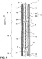
- the Fig. 1 shows in a cross section a first particularly preferred embodiment of an evaporation unit 1.
- the evaporation unit 1 is bounded with a tubular housing 3 made of steel outside.
- the evaporation unit 1 can be subdivided into three (3) subregions, namely into a first evaporation section 9, a second evaporation section 15 and a reactor chamber 16.
- the central component of the evaporation unit 1 is the centrally arranged meandering flow channel 4, which is bounded by a wall 7 comprising a tube 10 made of titanium. With the tube 10 made of titanium, a wave-shaped course of the flow channel 4 is realized in the two evaporation sections 9, 15. In particular, urea water solution enters the inlet 5 in liquid form and then passes through the first evaporation section 9.
- the tube 10 is surrounded by a base body 13 which is formed in particular of an aluminum material or a copper material. Like the tube 10 made of titanium, the heating conductor 8 is also cast into the base body 13.
- the ceramic layer 32 may in particular with a. Be executed ceramic powder.
- an additional ceramic tube 33 is provided between the ceramic layer 32 and the housing 3. The ceramic layer 32 and the ceramic tube 33 together form a thermal insulation 14.
- thermal insulation 14 and the housing 3 and the tube 10 made of titanium are integrally formed via the first evaporation section 9 and the second evaporation section 15, in each of the first evaporation section 9 and the second evaporation section 15 each have a separate base body 13 is provided. Likewise, different heating conductors 8, optionally with separate terminals, are formed here.
- a gap 34 is provided between the two base bodies 13, which in particular represents a thermal insulation in the axial direction.
- the temperature profiles of the first evaporation section 9 and the second evaporation section 15 should, if appropriate, be regulated or adjusted separately from one another.
- the flow channel 4 is designed differently, namely with a (widened, straight) transition section 35.
- a distance 12 between the heating conductor 8 and the flow channel 4 are essentially the same.
- the main body 13 subsequently has a widening 37 into which the hitherto (almost) completely evaporated urea-hydrogen solution dissolves. After that a reactor space 16 is formed, in which a honeycomb body 36 with a hydrolysis coating 11 is provided. The completely converted to ammonia gas now leaves the evaporation unit 1 and can flow into the exhaust system.
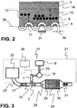
- the Fig. 2 shows a detail of another embodiment of the evaporation unit 1 in partial cross section. Down in Fig. 2 is shown as the flow channel 4 regularly oscillates about a central axis 38.
- the flow channel 4 has a diameter 39 of, for example, 4 mm.
- a hydrolysis coating 11 is also provided in the interior of the flow channel 4 or on its wall 7, a hydrolysis coating 11 is also provided.
- the flow channel 4 is cast in a Grundköper 13, in which the heating conductors 8 are provided in the manner of a helical winding. In the left area while a heating element 8 is indicated, which is positioned at a certain distance 12 to the flow channel 4.
- Fig. 3 now shows schematically a motor vehicle 21, in particular a passenger car or a truck.
- the exhaust gas generated in the internal combustion engine 22 is now cleaned via a corresponding exhaust system 23 and released to the environment.
- the exhaust gas first flows through a catalytic converter 27 (for example an oxidation catalytic converter) in the flow direction 31 in order finally to strike an SCR catalytic converter body 24 further downstream.
- a catalytic converter 27 for example an oxidation catalytic converter
- SCR catalytic converter body 24 further downstream.
- the connection 25 is provided for the evaporation unit 1 according to the invention, so that there the gas stream 2 comprising ammonia is introduced.
- the exhaust stream flowed with ammonia then optionally reaches a flow influencer 28 (eg a static mixer), before this mixture reaches the SCR catalyst body 24.
- a flow influencer 28 eg a static mixer
- the SCR catalytic converter can be provided in the inlet region 29 and / or in the outlet region 30 with further exhaust gas treatment components, such as a particle separator in the inlet region 29 and / or a. It should also be noted that other exhaust gas treatment devices may be provided in the exhaust system 23.
- the vaporization unit 1 is now connected to a reservoir 18 via several line sections 20.
- a reservoir 18 for example liquid urea-water solution is provided, which is then supplied by means of a metering pump 19 time and / or volume of the evaporation unit 1.
- the metering pump 19, the evaporation unit 1 and / or the internal combustion engine 22 with a controller 26 may be connected to here a controlled admixture of urea-water solution to the evaporation unit or ammonia gas to the exhaust gas guarantee.
- a device 17 comprising at least one reservoir 18, a line section 20, a metering pump 19 and an evaporation unit 1 may also be offered in any quantities as a component set with or without control 26.
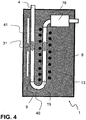
- the Fig. 4 schematically shows an embodiment variant with an evaporation unit 1 with a main body 13, which is shown here in section.
- the flow channel 4 is provided, wherein it initially extends in a direction in the base body 13 inside.
- a plurality of PTC elements for electrically heating the flow channel 4 and the flowing therein in the flow direction 31 gas-liquid mixture.
- This area now forms a first evaporation section 9.
- a turning section 40 is provided, in which the flow direction 31 is turned by 180 °.
- a second evaporation section 15 is formed.
- a coaxial heating conductor 8 is provided to this section of the flow channel 4.
- Fig. 5 shows schematically and in a cross section of a further embodiment of an evaporation unit 1.
- This comprises a housing 2 in the manner of a tube, wherein the central flow channel 4 and coaxially thereto a heating element 8 are arranged.
- the flow channel 4 and the heating conductor 8 are surrounded with copper granules 42, so that by a corresponding contact of the copper granules 42 with the flow channel 4 on the one hand and the heating element 8 on the other hand heat transfer can take place.
- the copper granulate 42 arranged between the flow channel 4 and the heating conductor 8 is pressed.
Description
Die vorliegende Erfindung betrifft eine Verdampfungseinheit zur Erzeugung eines Ammoniak umfassenden Gasstroms. Eine solche Verdampfungseinheit findet insbesondere Anwendung zur Bereitstellung gasförmigen Ammoniaks aus einem Ammoniak-Vorläufer, insbesondere in flüssiger und/oder fester Form. Die Erfindung findet insbesondere auch Anwendung im Rahmen der Abgasnachbehandlung bei Kraftfahrzeugen.The present invention relates to an evaporation unit for generating a gas stream comprising ammonia. Such an evaporation unit finds particular application for the provision of gaseous ammonia from an ammonia precursor, in particular in liquid and / or solid form. The invention finds particular application in the context of exhaust aftertreatment in motor vehicles.
Aus
Insbesondere bei Dieselverbrennungsmaschinen hat es sich bewährt, dem von der Verbrennungskraftmaschine erzeugten Abgas Harnstoff in wässriger Lösung direkt oder nach einer abgas-externen Hydrolyse Ammoniak zuzugeben. Hierbei kommt bei bekannten Verfahren ein Hydrolyse-Katalysator zum Einsatz, an dem aus dem Harnstoff Ammoniak gewonnen wird. Die wässrige Harnstofflösung wird stromauf des Hydrolyse-Katalysators zugegeben, in gasförmigen Zustand überführt und mit dem Hydrolyse-Katalysator in Kontakt gebracht. Der dabei generierte Ammoniak reagiert dann beispielsweise mit einem so genannten SCR-Katalysator weiter stromabwärts im Abgasstrom mit den dort enthaltenen Stickoxiden zu molekularen Stickstoff und Wasser.Particularly in the case of diesel internal combustion engines, it has proven useful to add ammonia to the exhaust gas produced by the internal combustion engine in aqueous solution directly or after external hydrolysis of the exhaust gas. In this case, in known processes a hydrolysis catalyst is used, on which ammonia is recovered from the urea. The aqueous urea solution is added upstream of the hydrolysis catalyst, converted into a gaseous state, and contacted with the hydrolysis catalyst. The generated ammonia then reacts, for example with a so-called SCR catalyst further downstream in the exhaust stream with the nitrogen oxides contained therein to molecular nitrogen and water.
Bei der Verdampfung der wässrigen Harnstofflösung ist die Temperaturführung besonders schwierig. Dies ist gerade unter dem Aspekt zu berücksichtigen, dass die benötigten Mengen der Harnstofflösung einerseits und die verfügbaren Temperaturen andererseits während einer mobilen Anwendung stark variieren können. Wird eine Verdampfung nicht vollständig erreicht, können sich Zwischenprodukte bilden, die gegebenenfalls zur Verstopfung der Verdampfereinheit führen können. Derartige, unerwünschte, Nebenprodukte sind beispielsweise wasserunlösliches Biuret, das sich aus Isocyansäure und Harnstoff bildet, und Cyanursäure, welche das Trimerisierungsprodukt der Isocyansäure darstellt. Bei der Verdampfung eines Ammoniak-Vorläufers, insbesondere einer flüssigen Harnstoff Wasser-Lösung, wurde beobachtet, dass die Temperatureinbringung in die Flüssigkeit sehr schnell über einen kritischen Temperaturbereich hinweg erfolgen muss, um die Bildung der genannten unerwünschten, teilweise nicht mehr entfernbaren, Verbindungen zu vermeiden.In the evaporation of the aqueous urea solution, the temperature control is particularly difficult. This is to be taken into account precisely in view of the fact that the required amounts of urea solution on the one hand and the available temperatures on the other hand can vary widely during a mobile application. If evaporation is not fully achieved, intermediates may form that may eventually block the evaporator unit. Such unwanted by-products are, for example, water-insoluble biuret, which is formed from isocyanic acid and urea, and cyanuric acid, which represents the trimerization product of isocyanic acid. In the evaporation of an ammonia precursor, particularly a liquid urea-water solution, it has been observed that the temperature introduction into the liquid must occur very rapidly over a critical temperature range to avoid the formation of said unwanted, sometimes non-removable compounds ,
Es sind bereits Vorrichtungen zur abgas-externen Verdampfung einer Harnstoff Wasser-Lösung beschrieben worden, allerdings konnten diese bislang zumindest für den Einsatz im Automobilbereich nicht überzeugen. Die bekannten Verdampfungsvorrichtungen können hier teilweise nicht die gewünschte Vollständigkeit der Verdampfung über alle Betriebszustände und/oder Mengen des zu verdampfenden Ammoniak-Vorläufers garantieren. Dies trifft insbesondere dann zu, wenn eine hochdynamische Regelung der Verdampfungseinheit unter Berücksichtigung von Betriebszuständen einer mobilen Verbrennungskraftmaschine, wie beispielweise einem Diesel-Motor, gegeben ist.Devices have already been described for the off-gas evaporation of a urea-water solution, but these have so far not been convincing, at least for use in the automotive sector. The known evaporation devices can not guarantee in part the desired completeness of the evaporation over all operating conditions and / or quantities of the ammonia precursor to be evaporated. This is especially true when a highly dynamic control of the evaporation unit, taking into account operating conditions of a mobile internal combustion engine, such as a diesel engine, given.
Hiervon ausgehend ist es Aufgabe der vorliegenden Erfindung, die mit Bezug auf den Stand der Technik geschilderten Probleme zumindest teilweise zu lösen. Insbesondere soll eine Verdampfungseinheit angegeben werden, die ein schnelles und vollständiges Verdampfen einer Harnstoff Wasser-Lösung zur Erzeugung eines Ammoniak umfassenden Gasstroms in exakt vorgegebenen quantitativen Mengen hochdynamisch bereitstellt. Dabei soll die Verdampfungseinheit kompakt und einfach aufgebaut sein. Außerdem wird gewünscht, dass die Verdampfungseinheit kostengünstig herstellbar ist.On this basis, it is an object of the present invention, at least partially solve the problems described with reference to the prior art. In particular, an evaporation unit is to be specified, which provides a fast and complete evaporation of a urea-water solution for generating a gas stream comprising ammonia in exactly predetermined quantitative amounts highly dynamically. The evaporation unit should be compact and simple. In addition, it is desired that the evaporation unit can be produced inexpensively.
Diese Aufgaben werden gelöst mit einer Verdampfungseinheit gemäß den Merkmalen des Patentanspruchs 1. Vorteilhafte Ausgestaltungen der Verdampfungseinheit werden in den abhängig formulierten Patentansprüchen angegeben. Die in den abhängig formulierten Patentansprüchen einzeln angegebenen Merkmale sind in beliebiger, technologisch sinnvoller, Weise miteinander kombinierbar und zeigen weitere Ausgestaltungen der Erfindung auf. Die Erfindung wird zudem durch die Beschreibung, insbesondere im Zusammenhang mit den Figuren, weiter charakterisiert und präzisiert.These objects are achieved with an evaporation unit according to the features of
Die erfindungsgemäße Verdampfungseinheit zur Erzeugung eines Ammoniak umfassenden Gasstroms weist zumindest auf:
- ein Gehäuse,
- wenigstens einen mäanderförmigen Strömungskanal mit einem Einlauf und einem Auslauf, der von einer geschlossenen Wand begrenzt ist,
- wenigstens einen Heizleiter, der zumindest in einem ersten Verdampfungsabschnitt eines wenigstens einen Strömungskanal zwischen Gehäuse und der Wand angeordnet ist und koaxial verläuft.
- a housing,
- at least one meandering flow channel having an inlet and an outlet delimited by a closed wall,
- at least one heating conductor, which is arranged at least in a first evaporation section of at least one flow channel between the housing and the wall and extends coaxially.
Die Verdampfungseinheit ist bevorzugt sehr kompakt aufgebaut und beispielsweise Rohr-ähnlicher Gestalt. Die äußeren Abmessungen einer solchen Verdampfungseinheit sind beispielsweise eine Länge von ca. 400 mm und ein Durchmesser im Bereich von 50 mm. Diese Verdampfungseinheit ist somit insbesondere dazu geeignet, Teil eines Leitungsabschnitts einer Abgasanlage einer mobilen Verbrennungskraftmaschine und/oder Teil eines Leitungsabschnitts eines in die Abgasleitung mündenden Zusatzsystems zu sein.The evaporation unit is preferably very compact and, for example, tube-like shape. The outer dimensions of such an evaporation unit are for example a length of about 400 mm and a diameter in the range of 50 mm. This evaporation unit is therefore particularly suitable for being part of a line section of an exhaust system of a mobile internal combustion engine and / or part of a line section of an auxiliary system opening into the exhaust line.
Das Gehäuse ist regelmäßig mit einem Stahl-Werkstoff gebildet. Es wird besonders bevorzugt, dass das Gehäuse ein Stahlrohr ist. Bei dem Gehäuse ist nicht zwingend eine Hochtemperatur-Festigkeit und/oder eine besonders hohe Korrosionsbeständigkeit erforderlich, weil die Verdampfungseinheit regelmäßig außerhalb der mit Abgas beströmten und folglich heißen Bereiche des Abgassystems angeordnet ist.The housing is regularly formed with a steel material. It is particularly preferred that the housing is a steel tube. In the case of a high-temperature strength and / or a particularly high corrosion resistance is not necessarily required because the evaporation unit is regularly arranged outside of the exhaust gas flowed and therefore hot areas of the exhaust system.
Der Strömungskanal ist "mäanderförmig" ausgebildet. Das heißt zunächst einmal (nur), dass ein nicht-gradliniger Verlauf des Strömungskanals verwirklicht ist. Ganz besonders bevorzugt ist, dass der Strömungskanal eine periodische Verlaufsänderung um eine zentrale Achse des Strömungskanals bzw. der Verdampfungseinheit durchführt. Dieser mäanderförmige Verlauf wird insbesondere durch einen wellenförmigen Verlauf beschrieben. Die Anzahl der Strömungskanäle kann entsprechend den gewünschten Bedingungen gewählt werden, bevorzugt ist die Ausgestaltung mit einem einzigen mäanderförmigen Strömungskanal. Gegebenenfalls ist aber auch möglich, dass wenigstens ein weiterer (z.B. bei Bedarf hinzu schaltbarer) Strömungskanal vorgesehen ist (z.B. für die Bereitstellung von relativ viel Ammoniakgas).The flow channel is "meandering" formed. This means first of all (only) that a non-straight course of the flow channel is realized. It is very particularly preferred that the flow channel carries out a periodic change in course about a central axis of the flow channel or of the evaporation unit. This meandering course is described in particular by a wave-shaped course. The number of flow channels can be selected according to the desired conditions, preferred is the embodiment with a single meandering flow channel. Optionally, however, it is also possible to provide at least one further flow channel (e.g., switchable if necessary) (e.g., for the provision of relatively much ammonia gas).
Bezüglich des Einlaufs ist zu erwähnen, dass dieser regelmäßig mit einer Pumpe und/oder einen Reservoir verbunden werden kann, also somit die Einleitung des Ammoniak-Vorläufers (z.B. Harnstoff-Wasser-Lösung) in die Verdampfungseinheit bzw. in den mäanderförmigen Strömungskanal realisiert. Auf der gegenüberliegenden Seite ist dann regelmäßig der Auslass vorgesehen, aus dem (praktisch reines) Ammoniakgas den Strömungskanal verlässt. Der Strömungskanal wird regelmäßig von einer einzelnen, geschlossenen und insbesondere separaten Wand begrenzt. Die Wand sorgt dafür, dass der zugeführte Ammoniak-Vorläufer vollständig verdampft wird und am Auslauf wieder austritt.With regard to the inlet, it should be mentioned that it can be regularly connected to a pump and / or a reservoir, thus thus implementing the introduction of the ammonia precursor (for example urea-water solution) into the evaporation unit or into the meandering flow channel. On the opposite side is then regularly provided the outlet from the (virtually pure) ammonia gas leaves the flow channel. The flow channel is regularly bounded by a single, closed and in particular separate wall. The wall ensures that the supplied ammonia precursor is completely evaporated and exits again at the outlet.
Darüber ist wenigstens ein Heizleiter vorgesehen. Der Heizleiter ist insbesondere ein elektrischer Heizleiter, der schnell und bedarfsgerecht hohe Temperaturen erreicht. Bevorzugt ist, dass (nur) ein Heizleiter im Verdampfungsabschnitt vorgesehen ist, gegebenenfalls kann hier aber auch (für einen bestimmten Bereich) eine weitere Heizleiteranordnung oder mehrere weitere Heizleiter vorgesehen sein. Der Heizleiter verläuft zudem koaxial zum Strömungskanal. Dabei ist insbesondere gemeint, dass der Heizleiter nach Art von Schlaufen, einer Wendel oder dergleichen um den Strömungskanal herum angeordnet ist. Dazu ist der Heizleiter gegebenenfalls mit einer entsprechenden Strom- bzw. Spannungsversorgung zu versehen. Demzufolge sind elektrische Anschlüsse an der Verdampfungseinheit vorzusehen, die gegebenenfalls mit einer geeigneten Steuerung zu verbinden sind. Der Heizleiter wird dabei unter Strom (zeitweise) gesetzt und erzeugt aufgrund der Ohmschen Widerstandserwärmung Wärme, die (mittelbar) auch an den Strömungskanal bzw. dessen Wand übertragen wird. Durch die Anordnung mehrerer Heizleiter in dem zumindest einen ersten Verdampfungsabschnitt kann die Temperatur des zu erzeugenden Gasstromes innerhalb des Strömungskanals gezielt beeinflusst werden.In addition, at least one heating element is provided. The heating conductor is in particular an electrical heating conductor which reaches high temperatures quickly and as needed. It is preferred that (only) a heating element is provided in the evaporation section, but if appropriate, a further heating element arrangement or a plurality of further heating conductors may also be provided here (for a certain area). The heating conductor also runs coaxially to the flow channel. It is meant in particular that the heating element is arranged in the manner of loops, a helix or the like around the flow channel around. This is the heating conductor if necessary, to be provided with an appropriate current or voltage supply. As a result, electrical connections to the evaporation unit are to be provided, which if necessary are to be connected to a suitable controller. The heating element is energized (temporarily) and generates heat due to ohmic resistance heating, which is also transmitted (indirectly) to the flow channel or its wall. By arranging a plurality of heating conductors in the at least one first evaporation section, the temperature of the gas flow to be generated within the flow channel can be influenced in a targeted manner.
Dieser sehr kompakte Aufbau erlaubt durch die Positionierung des Heizleiters eine schnelle Einbringung der Wärme und damit eine besonders schnelle Temperaturerhöhung in den mäanderförmigen Strömungskanal, durch den der Ammoniak-Vorläufer geleitet wird.Due to the positioning of the heating conductor, this very compact design allows a rapid introduction of the heat and thus a particularly rapid increase in temperature in the meandering flow channel, through which the ammonia precursor is passed.
Besonders bevorzugt ist in diesem Zusammenhang, dass die geschlossene Wand mit einem Rohr umfassend Titan gebildet ist. Insbesondere handelt es sich hierbei um ein im Wesentlichen aus Titan bestehendes Röhrchen (z.B. größer 90 Gew.-% Titan), in dessen Wand eine Wellstruktur eingebracht ist, wobei die Wellstruktur innen und/oder außen vorliegen kann. Das Rohr wird dabei beispielsweise mit einem Durchmesser kleiner als 6 mm bereitgestellt.Particularly preferred in this context is that the closed wall is formed with a tube comprising titanium. In particular, this is a tube consisting essentially of titanium (for example greater than 90% by weight of titanium), in the wall of which a corrugated structure is introduced, wherein the corrugated structure can be present inside and / or outside. The tube is provided, for example, with a diameter smaller than 6 mm.
Gemäß einer Weiterbildung der Erfindung wird vorgeschlagen, dass die Wand zumindest teilweise mit einer Hydrolyse-Beschichtung versehen ist. Die Hydrolyse-Beschichtung ist so ausgeführt, dass die Hydrolyse von Harnstoff hin zu Ammoniak begünstigt wird. Hierfür können poröse Beschichtungen, Oxide und/oder Salze eingesetzt werden, Für den Fall, dass die Wand des Strömungskanals mit Titan gebildet ist, wird insbesondere die Bereitstellung von Titanoxid auf der Wand vorgeschlagen, so dass dieses Titanoxid mit dem Ammoniak-Vorläufer in Kontakt tritt und die Umwandlung von Harnstoff-Wasser-Lösung zu Ammoniak begünstigt. Nur der Vollständigkeit sei darauf hingewiesen, dass die Hydrolyse-Beschichtung nur in einem Teil des ersten Verdampfungsabschnitts vorgesehen sein kann.According to one embodiment of the invention it is proposed that the wall is at least partially provided with a hydrolysis coating. The hydrolysis coating is designed to favor the hydrolysis of urea to ammonia. For this purpose, porous coatings, oxides and / or salts can be used. In the case that the wall of the flow channel is formed with titanium, in particular the provision of titanium oxide on the wall is proposed, so that this titanium oxide comes into contact with the ammonia precursor and the conversion of urea-water solution to ammonia favored. It should be pointed out only for completeness that the hydrolysis coating can be provided only in a part of the first evaporation section.
Außerdem wird auch vorgeschlagen, dass der wenigstens eine Heizleiter zumindest in dem ersten Verdampfungsabschnitt beabstandet zum Gehäuse und dem wenigstens einen Strömungskanal angeordnet ist. Das heißt mit anderen Worten auch, dass Mittel vorgesehen sind, die den Heizleiter sowohl mit einem Abstand zum Gehäuse als auch zu dem wenigstens einen Strömungskanal fixieren. Dabei kann dieser Abstand auch innerhalb eines Verdampferabschnitts in Strömungsrichtung des Ammoniak-Vorläufers variieren; der Heizleiter kann also einmal beispielsweise näher hin zum Gehäuse und einmal näher zum Strömungskanal positioniert sein. Durch den Abstand des Heizleiters zum Strömungskanal kann ebenfalls eine gezielte Beeinflussung des Temperaturprofils im Strömungskanal vorgenommen werden, wobei gleichzeitig auch eine intensive Verbindung mit einem der beiden Komponenten verhindert werden kann, was gegebenenfalls Vorteile bei der Wartung bzw. Instandsetzung solcher Heizleiter bringen kann.In addition, it is also proposed that the at least one heating conductor is arranged at least in the first evaporation section at a distance from the housing and the at least one flow channel. In other words, this means that means are provided which fix the heating conductor both with a distance to the housing and to the at least one flow channel. In this case, this distance can also vary within an evaporator section in the flow direction of the ammonia precursor; the heating conductor can thus be positioned, for example, closer to the housing and once closer to the flow channel. By the distance of the heating element to the flow channel can also be made a targeted influencing the temperature profile in the flow channel, at the same time an intensive connection with one of the two components can be prevented, which may possibly bring advantages in the maintenance or repair of such heating.
Darüber hinaus wird auch vorgeschlagen, dass zumindest der wenigstens eine Strömungskanal oder der wenigstens eine Heizleiter in einem, zumindest Aluminium oder Kupfer umfassenden, Grundkörper eingegossen ist. Insbesondere kann der (ggf. mehrteilig aufgebaute) Grundköper mit einem Mantel/Gehäuse aus Aluminium und darin befindlichen Kupfer-Komponenten ausgebildet sein. Bevorzugt ist, dass beide Elemente in einem (einzelnen) Grundköper vergossen sind. Das Vergießen von Heizleiter und Strömungskanal (bzw. die Wand des Strömungskanals) führt dazu, dass eine besonders gute Wärmeleitung vom Heizleiter hin zum Strömungskanal besteht. Aluminium als Werkstoff für den Grundkörper hat den Vorteil, dass dieses Material besonders gut zu vergießen ist und eine ausgezeichnete Wärmeleitfähigkeit aufweist. Gleichzeitig wird das Gewicht der Verdampfungseinheit gering gehalten, was im Automobilbau immer eine wichtige Richtgröße ist.In addition, it is also proposed that at least the at least one flow channel or the at least one heating element is cast in a, at least aluminum or copper comprehensive, basic body. In particular, the base body (which may have a multi-part design) may be formed with a jacket / housing made of aluminum and copper components located therein. It is preferred that both elements are encapsulated in a (single) basic body. The casting of the heating conductor and the flow channel (or the wall of the flow channel) leads to a particularly good heat conduction from the heating conductor to the flow channel. Aluminum as a material for the main body has the advantage that this material is particularly easy to shed and has excellent thermal conductivity. At the same time, the weight of the evaporation unit low, which is always an important benchmark in the automotive industry.
Der Grundkörper kann insbesondere auch als Mittel zur Beabstandung des Heizleiters vom Gehäuse und dem Strömungskanal dienen. Insbesondere ist es möglich, ein strukturiertes bzw. mäanderförmiges Titanrohr mit Aluminium, Kupfer und/oder einem anderem wärmeleitfähigen Material mit einem niedrigeren Schmelzpunkt als Titan zu umgießen (Grundkörper). Dadurch kann insbesondere wieder ein Rohr-ähnlicher Körper mit einer "glatten" Außenwand erzeugt werden. In diese Außenwand kann dann ein Pfad für den mindestens einen Heizleiter eingebracht werden, z.B. nach Art eines Gewindes oder dergleichen. In diesen Pfad (z.B. nach Art einer Nut) kann nun der Heizleiter positioniert und mit dem Grundkörper verbunden (z.B. verlötet) werden.In particular, the base body can also serve as a means for spacing the heat conductor from the housing and the flow channel. In particular, it is possible to encase a structured or meandering titanium tube with aluminum, copper and / or another thermally conductive material having a lower melting point than titanium (main body). As a result, in particular, a pipe-like body with a "smooth" outer wall can be produced again. In this outer wall can then be introduced a path for the at least one heating conductor, e.g. in the manner of a thread or the like. In this path (for example in the manner of a groove), the heating conductor can now be positioned and connected (for example soldered) to the base body.
Gemäß einer weiteren vorteilhaften Ausführungsform ist zumindest der Strömungskanal oder der wenigstens eine Heizleiter in einem ein Kupfergranulat umfassenden Grundkörper angeordnet. Insbesondere werden der Strömungskanal und der wenigstens eine Heizleiter in einem Gehäuse (z.B. aus Aluminium) angeordnet und durch das Kupfergranulat fixiert. Das Kupfergranulat wird insbesondere verpresst, so dass eine ausreichende Kontaktierung des wenigstens einen Heizleiters und der Wand des Strömungskanals gewährleistet ist und ein entsprechender Wärmeübergang erfolgt. Die Verpressung des Kupfergranulats führt weiterhin insbesondere zu einer homogenen Verteilung des Kupfergranulats und ermöglicht somit einen gleichmäßigen Wärmeübergang von Heizleiter zu Strömungskanal. Der Einsatz von Kupfergranulat ist gegenüber dem Vergießen des Heizleiters und des Strömungskanals in einem Grundkörper insbesondere energetisch günstiger und prozesstechnisch einfacher auszuführen. Lunker und andere Inhomogenitäten des Gusskörpers müssen damit nicht überprüft werden. Auch wenn hier grundsätzlich Granulat aus Kupfer bevorzugt ist, können kumulativ und/oder alternativ Granulate aus anderem Material (wie z.B. Aluminium) ebenfalls eingesetzt werden, die eine ähnliche Wärmeleitung vom Heizleiter hin zum Strömungskanal ermöglichen.According to a further advantageous embodiment, at least the flow channel or the at least one heating conductor is arranged in a basic body comprising a copper granulate. In particular, the flow channel and the at least one heating conductor are arranged in a housing (eg of aluminum) and fixed by the copper granules. The copper granules are in particular pressed, so that a sufficient contact of the at least one heat conductor and the wall of the flow channel is ensured and a corresponding heat transfer takes place. The compression of the copper granules further leads in particular to a homogeneous distribution of the copper granules and thus enables a uniform heat transfer from heating conductor to flow channel. The use of copper granules is compared to the casting of the heat conductor and the flow channel in a body particularly energetically favorable and process easier to execute. Voids and other inhomogeneities of the casting do not need to be checked. Although in principle granules of copper are preferred here, cumulatively and / or alternatively granules of other material (such as aluminum) may also be used, which allow a similar heat conduction from the heating conductor towards the flow channel.
Nach einer Weiterbildung der Verdampfungseinheit ist vorgesehen, dass zwischen Gehäuse und dem wenigstens einen Heizleiter zumindest eine thermische Isolierung positioniert ist. Die thermische Isolierung umfasst insbesondere ein Material, das die Ausbreitung der Wärme, die von dem Heizleiter ausgeht, hin zum Gehäuse behindert (insbesondere im Vergleich zur Wärmeleitung mit dem Grundkörper). Geeignete Materialien sind hier insbesondere Beschichtungen und/oder separate Bauteile, die bevorzugt keramische Werkstoffe umfassen. In Kombination oder alternativ dazu wird vorgeschlagen, Vakuum-Räume vorzusehen, die ebenfalls eine Ausbreitung der Wärme behindern.According to a development of the evaporation unit, it is provided that at least one thermal insulation is positioned between the housing and the at least one heating conductor. In particular, the thermal insulation comprises a material which hinders the propagation of the heat emanating from the heating conductor towards the housing (in particular in comparison with the heat conduction with the main body). Suitable materials here are, in particular, coatings and / or separate components, which preferably comprise ceramic materials. In combination or alternatively, it is proposed to provide vacuum spaces, which also hinder the spread of heat.
Darüber wird als vorteilhaft angesehen, dass die Verdampfungseinheit mit einem ersten Verdampfungsabschnitt und einem zweiten Verdampfungsabschnitt ausgebildet ist und zumindest die Anordnung, Anzahl oder Gestalt von zumindest einem der folgenden Elemente variiert: mäanderförmiger Strömungskanal, Heizleiter, Wand, Grundkörper, Isolierung. Ganz besonders bevorzugt ist, dass eine Mehrzahl der genannten Elemente, insbesondere mindestens drei Elemente ausgehend vom ersten Verdampfungsabschnitt hin zum zweiten Verdampfungsabschnitt verschieden ist. Damit ist nicht nur gemeint, dass innerhalb der Verdampfungsabschnitte eine Veränderung hinsichtlich Anordnung, Anzahl oder Gestalt der Elemente vorliegt, vielmehr kann alternativ oder kumulativ in dem Zwischenbereich zwischen den Verdampfungsabschnitten eine Variation vorgesehen sein. Im Hinblick auf den mäanderförmigen Strömungskanal kann insbesondere die Anzahl der zum Einsatz gelangenden Strömungskanäle, die Verlaufsform, das den Strömungskanal bildende Material und/oder der Querschnitt des Strömungskanals variiert werden. Im Hinblick auf den Heizleiter wird beispielsweise die Heizleistung, die Anzahl der Heizleiter, der Abstand des Heizleiter hin zum Strömungskanal und/oder zum Gehäuse und/oder der Steuerung des Heizleiters als variierbar angesehen. Bezüglich der Wand sei beispielhaft angerührt, dass hier Material, Beschichtung und/oder Wanddicke angepasst werden können. Der Grundkörper kann beispielsweise in einem Verdampfungsabschnitt und/oder zwischen mehreren Verdampfungsabschnitten mit Hohlräumen, zusätzliche Materialien oder dergleichen ausgeführt sein. Auch die. Isolierung kann in den Verdampfungsabschnitten selbst und/oder in den Zwischenräumen verändert werden, beispielsweise durch die Anzahl der Isolierschichten und/oder die hierzu eingesetzten Materialien.In addition, it is considered advantageous that the evaporation unit is formed with a first evaporation section and a second evaporation section and at least the arrangement, number or shape of at least one of the following elements varies: meandering flow channel, heating conductor, wall, base body, insulation. It is very particularly preferred that a plurality of said elements, in particular at least three elements, be different starting from the first evaporation section to the second evaporation section. This not only means that there is a change in the arrangement, number or shape of the elements within the evaporation sections, but alternatively, alternatively or cumulatively, a variation may be provided in the intermediate region between the evaporation sections. With regard to the meandering flow channel, in particular the number of flow channels used, the shape of the flow, the channel forming material and / or the cross section of the flow channel can be varied. With regard to the heating conductor, for example, the heating power, the number of heating conductors, the distance of the heating conductor to the flow channel and / or the housing and / or the control of the heating element as varied considered. With regard to the wall, it should be mentioned by way of example that material, coating and / or wall thickness can be adapted here. The base body can be embodied, for example, in an evaporation section and / or between a plurality of evaporation sections with cavities, additional materials or the like. Also the. Insulation can be changed in the evaporation sections themselves and / or in the interstices, for example by the number of insulating layers and / or the materials used for this purpose.
Außerdem wird auch als vorteilhaft angesehen, dass die Verdampfungseinheit mit einem ersten Verdampfungsabschnitt und einem zweiten Verdampfungsabschnitt ausgebildet ist, wobei der erste Verdampfungsabschnitt und der zweite Verdampfungsabschnitt parallel zueinander angeordnet und mit einem Wendeabschnitt miteinander verbunden sind. Bei der hier vorgeschlagenen Variante mit einem ersten Verdampfungsabschnitt und einem zweiten Verdampfungsabschnitt soll eine besonders kompakte Anordnung erreicht werden. Dazu verläuft der Strömungskanal zumindest für einen Bereich benachbart zu sich selbst bzw. in paralleler Anordnung. Dabei ist festzuhalten, dass "parallel" nicht streng im mathematischen Sinne angesehen werden kann, sondern es kommt hierbei im Wesentlichen darauf an, dass der Strömungskanal benachbart zueinander verläuft, um gerade so platzsparend in der Verdampfungseinheit positioniert werden zu können und zudem gegebenenfalls ein Wärmeaustausch der benachbart zueinander angeordneten Bereiche des Strömungskanal erlaubt beziehungsweise begünstigt ist. Diese beiden parallelen Verdampfungsabschnitte sind mit einem Wendeabschnitt miteinander verbunden, der beispielsweise nach Art einer halbreisförmigen Umbiegung ausgeführt ist.In addition, it is also considered advantageous that the evaporation unit is formed with a first evaporation section and a second evaporation section, wherein the first evaporation section and the second evaporation section are arranged parallel to each other and connected to each other by a turn section. In the variant proposed here with a first evaporation section and a second evaporation section, a particularly compact arrangement is to be achieved. For this purpose, the flow channel extends at least for a region adjacent to itself or in a parallel arrangement. It should be noted that "parallel" can not be strictly considered in the mathematical sense, but it essentially depends on the fact that the flow channel adjacent to each other, just to save space in the evaporation unit can be positioned and also optionally a heat exchange of adjacent to each other arranged portions of the flow channel is allowed or favored. These two parallel evaporation sections are connected to one another with a turning section, which is designed, for example, in the manner of a semi-circular bend.
Bei dieser Variante ist es besonders bevorzugt, dass gleichzeitig verschiedene Heizleiter vorgesehen sind. So wird beispielsweise als vorteilhaft angesehen, dass im ersten Verdampfungsabschnitt selbstregelnde PTC-Elemente eingesetzt werden (positive temperature coefficient). Diese PTC-Elemente sind stromleitende Materialien, die bei tieferen Temperaturen den Strom besser leiten können als bei hohen. Der elektrische Widerstand vergrößert sich bei steigender Temperatur. Das bedeutet mit anderen Worten auch, dass mit steigender Temperatur die Heizleistung ebenfalls geringer wird. Dies kann insbesondere auch durch den benachbarten zweiten Verdampfungsabschnitt beeinflusst werden. In diesem zweiten Verdampfungsabschnitt ist bevorzugt der koaxial zum Strömungskanal angeordnete Heizleiter vorgesehen. Gegebenenfalls kann es auch sinnvoll sein, den Wendeabschnitt mit dem koaxial angeordneten Heizleiter auszufahren, um hier die gewünschten Temperaturen zu erreichen bzw. zu halten.In this variant, it is particularly preferred that different heating conductors are provided at the same time. For example, it is considered advantageous that self-regulating PTC elements are used in the first evaporation section (positive temperature coefficient). These PTC elements are conductive materials that conduct electricity better at lower temperatures than at high temperatures. The electrical resistance increases with increasing temperature. In other words, this also means that with increasing temperature, the heating power is also lower. This can in particular also be influenced by the adjacent second evaporation section. In this second evaporation section, the coaxial to the flow channel arranged heating conductor is preferably provided. Optionally, it may also be useful to extend the turning section with the coaxially arranged heating conductor in order to achieve or maintain the desired temperatures here.
Des Weiteren wird auch vorgeschlagen, dass benachbart zum Auslauf des wenigstens einen Strömungskanals zumindest ein Reaktorraum mit einer Hydrolyse-Beschichtung vorgesehen ist. Das bedeutet mit anderen Worten, dass hier bevorzugt eine mindestens zwei-stufige Hydrolyse innerhalb der Verdampfungseinheit (Abgas extern) durchgeführt wird. Für den Fall, dass mehrere Verdampfungsabschnitte vorgesehen sind, kann in wenigstens einem Verdampfungsabschnitt, bevorzugt aber in allen Verdampfungsabschnitten und dem Reaktorraum eine Hydrolyse erfolgen. Der Reaktorraum kann hierzu auch eine vergrößerte Anzahl von Strömungskanälen aufweisen, beispielsweise durch die Bereitstellung eines darin integrierten Wabenkörpers. Ein solcher Wabenkörper ist insbesondere mit einer Mehrzahl von zumindest teilweise strukturierten Metallfolien ausgeführt. Diese Metallfolien sind bevorzugt mit einer Hydrolyse-Beschichtung versehen. Auch in diesem Zusammenhang kann Titan als wesentlicher Werkstoff eingesetzt werden.Furthermore, it is also proposed that at least one reactor space with a hydrolysis coating is provided adjacent to the outlet of the at least one flow channel. In other words, this means that at least two-stage hydrolysis is preferably carried out within the evaporation unit (external gas). In the event that a plurality of evaporation sections are provided, hydrolysis can take place in at least one evaporation section, but preferably in all evaporation sections and the reactor space. The reactor space may for this purpose also have an increased number of flow channels, for example by providing a honeycomb body integrated therein. Such a honeycomb body is designed in particular with a plurality of at least partially structured metal foils. These metal foils are preferably provided with a hydrolysis coating. Also in this context, titanium can be used as an essential material.
Darüber hinaus wird eine Vorrichtung umfassend zumindest ein Reservoir, eine Dosierpumpe, eine Verdampfungseinheit der erfindungsgemäßen Art sowie zumindest ein, die vorstehenden Komponenten zumindest teilweise verbindenden, Leitungsabschnitt umfasst. Das Reservoir stellt gerade bei Einsatz einer Harnstoff-Wasser-Lösung, ein Flüssigkeitstank dar. Die Dosierpumpe, die bevorzugt zwischen Reservoir und Verdampfungseinheit positioniert ist, kann die Harnstoff-Wasser-Lösung in besonders kurzen Zeiträumen und mit sehr hoher Genauigkeit zur Verdampfungseinheit zuführen. Der Leitungsabschnitt ist bevorzugt mit einem Aluminium- und/oder Stahl-Rohr gebildet. Zusätzlich kann die Vorrichtung Sensoren und/oder eine (elektrische) Steuerung und/oder Ventile umfassen.In addition, a device comprising at least one reservoir, a metering pump, an evaporation unit of the type according to the invention and at least one, the above components at least partially connecting line section comprises. The reservoir is just when using a urea-water solution, a liquid tank. The metering pump, the preferred is positioned between the reservoir and evaporation unit, the urea-water solution can supply to the evaporation unit in very short periods of time and with very high accuracy. The line section is preferably formed with an aluminum and / or steel tube. In addition, the device may include sensors and / or an (electrical) control and / or valves.
Ganz besonders bevorzugt wird auch ein Kraftfahrzeug mit einer Verbrennungskraftmaschine und einer Abgasanlage vorgeschlagen, wobei die Abgasanlage zumindest einen SCR-Katalysatorkörper aufweist und zwischen der Verbrennungskraftmaschine und dem zumindest einen SCR-Katalysatorkörper wenigstens ein Anschluss mit einer Verdampfungseinheit der erfindungsgemäßen Art oder einer Vorrichtung, wie vorstehend beschrieben, vorgesehen ist, so dass gasförmiger Ammoniak so in die Abgasanlage einleitbar ist, dass diese zum zumindest SCR-Katalysatorkörper strömt. Ganz besonders bevorzugt ist dabei, dass zwischen dem Auslauf des mäanderförmigen Strömungskanals bzw., soweit vorhanden, dem Ende des Reaktorraums einerseits und dem Anschluss bzw. der Abgasanlage andererseits kein weiteres Ventil vorgesehen ist. Gegebenenfalls kann der Anschluss noch Mittel zur Verteilung des Ammoniak umfassenden Gasstroms, welcher die Verdampfungseinheit verlässt und dem Abgas in der Abgasanlage zugeführt wird, aufweisen.Very particular preference is also a motor vehicle with an internal combustion engine and an exhaust system is proposed, wherein the exhaust system comprises at least one SCR catalyst body and between the internal combustion engine and the at least one SCR catalyst body at least one connection with an evaporation unit of the type according to the invention or a device, as above is described, is provided so that gaseous ammonia can be introduced into the exhaust system so that it flows to the at least SCR catalyst body. It is very particularly preferred that no further valve is provided between the outlet of the meandering flow channel or, if present, the end of the reactor chamber on the one hand and the connection or the exhaust system on the other. If appropriate, the connection can also have means for distributing the ammonia-comprising gas stream which leaves the evaporation unit and is supplied to the exhaust gas in the exhaust system.
Als SCR-Katalysatorkörper wird üblicher Weise ein (keramischer, extrudierter) Wabenkörper eingesetzt, der z.B. eine SCR-Beschichtung aufweist. Eine solche SCR-Beschichtung ist bevorzugt vom V2O5/WO3/TiO2-Typ (Vanadiumpentoxid/Wolframtrioxid/Titandioxid).As the SCR catalyst body, a (ceramic extruded) honeycomb body is commonly used, e.g. having an SCR coating. Such an SCR coating is preferably of the V2O5 / WO3 / TiO2 type (vanadium pentoxide / tungsten trioxide / titanium dioxide).
Die Erfindung sowie das technische Umfeld werden nachfolgend anhand der Figuren näher erläutert. Es ist darauf hinzuweisen, dass die in den Figuren veranschaulichten Ausführungsvarianten die Erfindung nicht beschränken sollen. Für gleiche Gegenstände werden in den Figuren auch gleiche Bezugszeichen verwendet. Es zeigen schematisch:
- Fig. 1:
- eine Ausführungsvariante einer erfindungsgemäßen Verdampfungseinheizt,
- Fig. 2:
- ein Detail einer weiteren Ausführungsform einer Verdampfungseinheit,
- Fig. 3:
- schematisch den Aufbau eines SCR-Systems bei einem Kraftfahrzeug,
- Fig. 4:
- einen weiteren Aufbau einer Verdampfungseinheit, und
- Fig. 5:
- einen Querschnitt durch einen weiteren Aufbau einer Verdampfungseinheit mit Kupfergranulat.
- Fig. 1:
- an embodiment variant of an evaporation according to the invention,
- Fig. 2:
- a detail of another embodiment of an evaporation unit,
- 3:
- schematically the structure of an SCR system in a motor vehicle,
- 4:
- another structure of an evaporation unit, and
- Fig. 5:
- a cross section through another structure of an evaporation unit with copper granules.
Die
Zentrales Bauteil der Verdampfungseinheit 1 ist der zentral angeordnete mäanderförmige Strömungskanal 4, der mit einer Wand 7 umfassend ein Rohr 10 aus Titan begrenzt ist. Mit dem Rohr 10 aus Titan ist in den beiden Verdampfungsabschnitten 9, 15 ein wellenförmiger Verlauf des Strömungskanals 4 realisiert. Dabei tritt insbesondere Harnstoff Wasser-Lösung in den Einlauf 5 in flüssiger Form ein und durchläuft dann den ersten Verdampfungsabschnitt 9.The central component of the
Das Rohr 10 ist von einem Grundkörper 13 umgeben, der insbesondere aus einem Aluminium-Werkstoff oder einem Kupfer-Werkstoff gebildet ist. Wie das Rohr 10 aus Titan so ist auch der Heizleiter 8 mit in den Grundkörper 13 eingegossen. Der hier zylindrisch ausgeführte Grundkörper 13 erstreckt sich im Wesentlichen über die Länge des ersten. Verdampfungsabschnitts 9 und wird außen durch eine Keramikschicht 32 begrenzt. Die Keramikschicht 32 kann insbesondere mit einem. Keramikpulver ausgeführt sein. Weiter außen, zwischen der Keramikschicht 32 und dem Gehäuse 3, ist ein zusätzliches Keramikrohr 33 vorgesehen. Die Keramikschicht 32 und das Keramikrohr 33 bilden zusammen eine thermische Isolierung 14. Während die thermische Isolierung 14 und das Gehäuse 3 sowie das Rohr 10 aus Titan über den ersten Verdampfungsabschnitt 9 und den zweiten Verdampfungsabschnitt 15 einteilig ausgebildet sind, sind in jeweils dem ersten Verdampfungsabschnitt 9 und dem zweiten Verdampfungsabschnitt 15 jeweils ein separater Grundkörper 13 vorgesehen. Ebenso sind hier unterschiedliche Heizleiter 8, gegebenenfalls mit separaten Anschlüssen, ausgebildet.The
Zwischen den beiden Grundkörpern 13 ist zudem ein Spalt 34 vorgesehen, der insbesondere in axialer Richtung eine thermische Isolierung darstellt. Damit sollen die Temperaturprofile von erstem Verdampfungsabschnitt 9 und zweitem Verdampfungsabschnitt 15 gegebenenfalls getrennt voneinander regel- bzw. einstellbar sein. Im Übergangsbereich zwischen ersten Verdampfungsabschnitt 9 und zweitem Verdampfungsabschnitt 15 ist auch der Strömungskanal 4 anders ausgestaltet, hier nämlich mit einem (verbreiterten, gradlinigen) Übergangsabschnitt 35. Im ersten Verdampfungsabschnitt 9 und im zweiten Verdampfungsabschnitt 15 ist ein Abstand 12 zwischen dem Heizleiter 8 und dem Strömungskanal 4 im Wesentlichen gleich.In addition, a
Im Bereich des Auslaufs 6 des Strömungskanals 4 weist der Grundkörper 13 nachfolgend eine Aufweitung 37 auf, in welche die bis dahin (nahezu) vollständig verdampfte Harnstoff-Wasserstoff-Lösung hinein entspannt. Daran anschließend ist ein Reaktorraum 16 ausgebildet, in dem ein Wabenkörper 36 mit einer Hydrolyse-Beschichtung 11 vorgesehen ist. Das vollständig zu Ammoniak umgewandelte Gas verlässt nun die Verdampfungseinheit 1 und kann in die Abgasanlage strömen.In the region of the outlet 6 of the
Die
Die erfindungsgemäße Verdarnpfungseinheit 1 ist nun über mehrere Leitungsabschnitte 20 mit einem Reservoir 18 verbunden. In dem Reservoir 18 ist beispielsweise flüssige Harnstoff-Wasser-Lösung vorgesehen, die dann mittels einer Dosierpumpe 19 zeit- und/oder volumengerecht der Verdampfungseinheit 1 zugeführt wird. Zu diesem Zweck können die Dosierpumpe 19, die Verdampfungseinheit 1 und/oder die Verbrennungskraftmaschine 22 mit einer Steuerung 26 (datentechnisch und/oder wirktechnisch) verbunden sein, um hier eine geregelte Beimengung von Harnstoff-Wasser-Lösung zur Verdampfungseinheit bzw. Ammoniakgas zum Abgas zu gewährleisten.The
Nur der Vollständigkeit halber sei auch darauf hingewiesen, dass eine Vorrichtung 17 umfassend wenigstens ein Reservoir 18, ein Leitungsabschnitt 20, eine Dosierpumpe 19 und eine Verdampfungseinheit 1 in beliebigen Stückzahlen auch separat als Komponentensatz mit/oder ohne Steuerung 26 angeboten werden kann.For the sake of completeness, it should also be pointed out that a
Die
- 11
- VerdampfungseinheitEvaporation unit
- 22
- Gasstromgas flow
- 33
- Gehäusecasing
- 44
- Strömungskanalflow channel
- 55
- Einlaufenema
- 66
- Auslaufoutlet
- 77
- Wandwall
- 88th
- Heizleiterheating conductor
- 99
- erster Verdampfungsabschnittfirst evaporation section
- 1010
- Rohrpipe
- 1111
- Hydrolyse-BeschichtungHydrolysis coating
- 1212
- Abstanddistance
- 1313
- Grundkörperbody
- 1414
- Isolierunginsulation
- 1515
- zweiter Verdampfungsabschnittsecond evaporation section
- 1616
- Reaktorraumreactor chamber
- 1717
- Vorrichtungcontraption
- 1818
- Reservoirreservoir
- 1919
- Dosierpumpemetering
- 2020
- Leitungsabschnittline section
- 2121
- Kraftfahrzeugmotor vehicle
- 2222
- VerbrennungskraftmaschineInternal combustion engine
- 2323
- Abgasanlageexhaust system
- 2424
- SCR-KatalysatorkörperSCR catalyst body
- 2525
- Anschlussconnection
- 2626
- Steuerungcontrol
- 2727
- Katalytischer KonverterCatalytic converter
- 2828
- StrömungsbeeinflusserFlow influencer
- 2929
- Eintrittsbereichentry area
- 3030
- Austrittsbereichexit area
- 3131
- Strömungsrichtungflow direction
- 3232
- Keramikschichtceramic layer
- 3333
- Keramikrohrceramic tube
- 3434
- Spaltgap
- 3535
- ÜbergangsabschnittTransition section
- 3636
- Wabenkörperhoneycombs
- 3737
- Aufweitungwidening
- 3838
- Achseaxis
- 3939
- Durchmesserdiameter
- 4040
- Wendeabschnittturn portion
- 4141
- PTC-ElementPTC element
- 4242
- Kupfergranulatcopper granules
Claims (12)
- Evaporation unit (1) for producing a gas flow (2) comprising ammonia, having at least:- a housing (3),- at least one meandering flow duct (4) with an inflow (5) and an outflow (6), which flow duct (4) is delimited by a closed wall (7),- at least one heat conductor (8) which is arranged at least in a first evaporation section (9) of the at least one flow duct (4) between the housing (3) and the wall (7) and which runs coaxially.
- Evaporation unit (1) according to Patent Claim 1, with the closed wall (7) being formed by a tube (10) comprising titanium.
- Evaporation unit (1) according to Patent Claim 1 or 2, with the wall (7) being at least partially provided with a hydrolysis coating (11).
- Evaporation unit (1) according to one of the preceding patent claims, with the at least one heat conductor (8) being arranged spaced apart from the housing (3) and the at least one flow duct (4) at least in the first evaporation section (9).
- Evaporation unit (1) according to one of the preceding patent claims, with at least the at least one flow duct (4) or the at least one heat conductor (8) being cast into a basic body (13) which comprises at least aluminum or copper.
- Evaporation unit (1) according to one of Patent Claims 1 to 4, with at least the at least one flow duct (4) and the at least one heat conductor (8) being arranged in a basic body (13) comprising copper granulate (42).
- Evaporation unit (1) according to one of the preceding patent claims, with at least one thermal insulation (14) being provided between the housing (3) and the at least one heat conductor (8).
- The evaporation unit (1) according to one of the preceding patent claims, with said evaporation unit (1) being formed with a first evaporation section (9) and a second evaporation section (15) and with at least the arrangement, number or design of at least one of the following elements varying: meandering flow duct (4), heat conductor (8), wall (7), basic body (13), insulation (14).
- Evaporation unit (1) according to one of the preceding patent claims, with said evaporation unit (1) being formed with a first evaporation section (9) and a second evaporation section (15), with the first evaporation section (9) and the second evaporation section (15) being arranged parallel to one another and being connected to one another via a bend section (40).
- Evaporation unit (1) according to one of the preceding patent claims, with at least one reactor chamber (16) with a hydrolysis coating (11) being provided adjacent to the outflow (6) of the at least one flow duct (4).
- Device (17) comprising at least one reservoir (18), a dosing pump (19), an evaporation unit (1) according to one of the preceding patent claims and also at least one line section (20) which at least partially connects the above components.
- Motor vehicle (21) having an internal combustion engine (22) and an exhaust system (23), with the exhaust system (23) having at least one SCR catalyst body (24), and with at least one port (25) with an evaporation unit (1) according to one of the preceding Patent Claims 1 to 10 or a device (17) according to Patent Claim 11 being provided between the internal combustion engine (22) and the at least one SCR catalyst body (24), such that gaseous ammonia can be conducted into the exhaust system (23) in such a way that said gaseous ammonia flows to the at least one SCR catalyst body (24).
Applications Claiming Priority (3)
| Application Number | Priority Date | Filing Date | Title |
|---|---|---|---|
| DE102008012087A DE102008012087A1 (en) | 2008-02-29 | 2008-02-29 | Evaporation unit for use with device of motor vehicle for producing gas flow comprising ammonia, has housing and meander-shaped flow channel with inlet and outlet, which is limited by closed wall |
| DE102008023938A DE102008023938A1 (en) | 2008-05-16 | 2008-05-16 | Aqueous solution e.g. urea-water-solution, evaporation unit for use in exhaust gas system of motor vehicle, has heat layer formed outside thermal conductive layer and connected in material fit to thermal conductive layer |
| PCT/EP2009/050901 WO2009109423A1 (en) | 2008-02-29 | 2009-01-28 | Evaporation unit for producing gaseous ammonia |
Publications (2)
| Publication Number | Publication Date |
|---|---|
| EP2244798A1 EP2244798A1 (en) | 2010-11-03 |
| EP2244798B1 true EP2244798B1 (en) | 2016-05-18 |
Family
ID=40823044
Family Applications (1)
| Application Number | Title | Priority Date | Filing Date |
|---|---|---|---|
| EP09718336.2A Not-in-force EP2244798B1 (en) | 2008-02-29 | 2009-01-28 | Evaporation unit for producing gaseous ammonia |
Country Status (6)
| Country | Link |
|---|---|
| US (1) | US8281573B2 (en) |
| EP (1) | EP2244798B1 (en) |
| JP (1) | JP5336519B2 (en) |
| KR (1) | KR101221701B1 (en) |
| CN (1) | CN101959567B (en) |
| WO (1) | WO2009109423A1 (en) |
Families Citing this family (17)
| Publication number | Priority date | Publication date | Assignee | Title |
|---|---|---|---|---|
| EP2257351B1 (en) * | 2008-02-29 | 2014-12-17 | Emitec Gesellschaft für Emissionstechnologie mbH | Evaporation unit for producing a gas comprising at least one reduction agent precursor and/or a reduction agent |
| DE102008048426A1 (en) * | 2008-09-23 | 2010-04-01 | Man Nutzfahrzeuge Aktiengesellschaft | Dosing device for dosing a reducing agent, in particular for a selective catalytic reduction, in an exhaust gas stream of an internal combustion engine |
| DE102009025135A1 (en) * | 2009-06-17 | 2010-12-23 | Emitec Gesellschaft Für Emissionstechnologie Mbh | Device for evaporating a urea-water solution |
| US8822887B2 (en) | 2010-10-27 | 2014-09-02 | Shaw Arrow Development, LLC | Multi-mode heater for a diesel emission fluid tank |
| JP5711578B2 (en) * | 2011-03-18 | 2015-05-07 | 日野自動車株式会社 | Urea water reformer and exhaust gas purification apparatus using the same |
| WO2012128145A1 (en) * | 2011-03-18 | 2012-09-27 | 日野自動車株式会社 | Urea solution reformer and exhaust gas purifier using same |
| CN103437865B (en) * | 2013-07-25 | 2015-12-09 | 吉林大学 | A kind of automotive SCR system ammonia production method and device |
| CN104548626A (en) * | 2013-10-15 | 2015-04-29 | 中国石油化工股份有限公司 | Liquid ammonia evaporation technology and device thereof for flue gas desulphurization system |
| DE102014005522A1 (en) * | 2014-04-15 | 2015-10-15 | Albonair Gmbh | Reducing agent dosing system with leakage monitoring |
| USD729141S1 (en) | 2014-05-28 | 2015-05-12 | Shaw Development LLC | Diesel emissions fluid tank |
| USD729722S1 (en) | 2014-05-28 | 2015-05-19 | Shaw Development LLC | Diesel emissions fluid tank floor |
| US9890682B2 (en) * | 2016-04-08 | 2018-02-13 | Caterpillar Inc. | System, apparatus, and method to address unwanted DEF-based deposits in diesel exhaust system |
| KR101985730B1 (en) * | 2016-09-26 | 2019-06-04 | (주)원익머트리얼즈 | Apparatus to generate and discharge ammonia |
| CN108096861B (en) * | 2017-12-12 | 2020-03-10 | 王兴辉 | Device for converting liquid ammonia into gas ammonia |
| FR3092364B1 (en) * | 2019-02-04 | 2021-01-01 | Cpt Group | Method of injecting ammonia in gaseous form into a heat engine exhaust line |
| DE102019107384A1 (en) * | 2019-03-22 | 2020-09-24 | Eberspächer Exhaust Technology GmbH & Co. KG | Exhaust heating element |
| JP7449842B2 (en) * | 2020-11-02 | 2024-03-14 | 信越化学工業株式会社 | Manufacturing method and manufacturing device for porous glass base material |
Family Cites Families (16)
| Publication number | Priority date | Publication date | Assignee | Title |
|---|---|---|---|---|
| CH642557A5 (en) * | 1979-07-26 | 1984-04-30 | Luwa Ag | DC EVAPORATOR. |
| DE4029260C1 (en) * | 1990-09-14 | 1992-05-14 | Krytem Gmbh, 4156 Willich, De | Appts. for dry evaporation of technical gases - includes insulating vessel contg. gas tube surrounded by heating tube with flow path between them |
| JP2923382B2 (en) * | 1991-08-30 | 1999-07-26 | 日野自動車工業株式会社 | Exhaust gas purification equipment for diesel engines |
| JPH07280356A (en) * | 1994-04-11 | 1995-10-27 | Fujikura Ltd | Evaporation block for heat accumulative type heat pipe hot water feeding device |
| CN1170080A (en) * | 1996-07-04 | 1998-01-14 | 王玉连 | Method and device for treating automotive exhaust |
| JP2000320997A (en) * | 1999-05-14 | 2000-11-24 | Osaka Gas Co Ltd | Surface modifying method, surface modified product, heating tube for evaporator and absorbing refrigerating machine |
| EP1193462A3 (en) * | 2000-09-29 | 2006-04-12 | Calsonic Kansei Corporation | Heat exchanger |
| JP4110948B2 (en) * | 2002-11-28 | 2008-07-02 | カシオ計算機株式会社 | Small chemical reactor and fuel cell system |
| JP2005344597A (en) * | 2004-06-02 | 2005-12-15 | Hitachi Ltd | Exhaust gas treating device for engines |
| WO2006025110A1 (en) * | 2004-09-02 | 2006-03-09 | Nissan Diesel Motor Co., Ltd. | Exhaust gas purifier |
| DE102005023956A1 (en) * | 2005-05-20 | 2006-11-23 | Universität Stuttgart | Compact total evaporator |
| JP4728124B2 (en) * | 2006-01-06 | 2011-07-20 | 日野自動車株式会社 | Exhaust purification device |
| DE102006023146A1 (en) * | 2006-05-16 | 2007-11-22 | Emitec Gesellschaft Für Emissionstechnologie Mbh | Method and device for providing a gaseous substance mixture |
| DE102006023148A1 (en) * | 2006-05-16 | 2007-11-22 | Emitec Gesellschaft Für Emissionstechnologie Mbh | Device for the treatment of exhaust gas of an internal combustion engine |
| DE102006023147A1 (en) * | 2006-05-16 | 2008-01-10 | Emitec Gesellschaft Für Emissionstechnologie Mbh | Method and device for providing a gaseous substance mixture |
| JP4696039B2 (en) * | 2006-09-21 | 2011-06-08 | 日立オートモティブシステムズ株式会社 | Urea water injection device for exhaust treatment equipment |
-
2009
- 2009-01-28 WO PCT/EP2009/050901 patent/WO2009109423A1/en active Application Filing
- 2009-01-28 JP JP2010548049A patent/JP5336519B2/en not_active Expired - Fee Related
- 2009-01-28 KR KR1020107020638A patent/KR101221701B1/en active IP Right Grant
- 2009-01-28 CN CN200980107070.4A patent/CN101959567B/en not_active Expired - Fee Related
- 2009-01-28 EP EP09718336.2A patent/EP2244798B1/en not_active Not-in-force
-
2010
- 2010-08-30 US US12/870,954 patent/US8281573B2/en active Active
Also Published As
| Publication number | Publication date |
|---|---|
| US20110041484A1 (en) | 2011-02-24 |
| KR101221701B1 (en) | 2013-01-11 |
| JP5336519B2 (en) | 2013-11-06 |
| US8281573B2 (en) | 2012-10-09 |
| JP2011516769A (en) | 2011-05-26 |
| WO2009109423A1 (en) | 2009-09-11 |
| CN101959567B (en) | 2014-06-04 |
| KR20100115370A (en) | 2010-10-27 |
| EP2244798A1 (en) | 2010-11-03 |
| CN101959567A (en) | 2011-01-26 |
Similar Documents
| Publication | Publication Date | Title |
|---|---|---|
| EP2244798B1 (en) | Evaporation unit for producing gaseous ammonia | |
| EP2057360B1 (en) | Method and device for providing a reducing agent-comprising gas flow | |
| EP2257351B1 (en) | Evaporation unit for producing a gas comprising at least one reduction agent precursor and/or a reduction agent | |
| EP2021100B1 (en) | Method for providing a gaseous mixture | |
| EP2101896B1 (en) | Method for the selective catalytic reduction of nitrogen oxides in the exhaust gas of an internal combustion engine and exhaust gas system | |
| EP2021101B1 (en) | Method and device for processing the waste gas of an internal combustion engine | |
| EP2326807B1 (en) | Exhaust gas purification system for diesel engines | |
| EP1977090B1 (en) | Device for the reduction of nitrogen oxides in the exhaust gas of internal combustion engines | |
| EP2443064B1 (en) | Apparatus for evaporating a urea-water solution | |
| EP2018470A1 (en) | Method for processing waste gas of an internal combustion engine | |
| EP2146791B1 (en) | Evaporator for mobile anhydrous ammonia production, and method for manufacturing such an evaporator | |
| EP2061580B1 (en) | Device for evaporating a reactant | |
| DE102009015419A1 (en) | Method for supplying reducing agent into an exhaust system and corresponding exhaust system | |
| EP3247889B1 (en) | Exhaust gas purification device for purifying exhaust gas of an internal combustion engine | |
| DE102006023146A1 (en) | Method and device for providing a gaseous substance mixture | |
| DE102008012087A1 (en) | Evaporation unit for use with device of motor vehicle for producing gas flow comprising ammonia, has housing and meander-shaped flow channel with inlet and outlet, which is limited by closed wall | |
| DE102008023938A1 (en) | Aqueous solution e.g. urea-water-solution, evaporation unit for use in exhaust gas system of motor vehicle, has heat layer formed outside thermal conductive layer and connected in material fit to thermal conductive layer | |
| WO2010040666A1 (en) | Method for operating an evaporator unit for producing gaseous ammonia | |
| DE102008012972A1 (en) | Aqueous solution e.g. urea-water-solution, evaporation unit for use in exhaust gas system of motor vehicle, has heat layer formed outside thermal conductive layer and connected in material fit to thermal conductive layer | |
| DE102007058486A1 (en) | Evaporation device for generating ammonia gas for supplying to motor vehicle exhaust system, has heating element in thermal conducting contact with evaporation section of meander-shaped channel | |
| DE102007023424A1 (en) | Evaporator device, has base body with inlet and drain, where heating element, with evaporation section of channel, is engaged in thermo-conducting manner |
Legal Events
| Date | Code | Title | Description |
|---|---|---|---|
| PUAI | Public reference made under article 153(3) epc to a published international application that has entered the european phase |
Free format text: ORIGINAL CODE: 0009012 |
|
| 17P | Request for examination filed |
Effective date: 20100817 |
|
| AK | Designated contracting states |
Kind code of ref document: A1 Designated state(s): AT BE BG CH CY CZ DE DK EE ES FI FR GB GR HR HU IE IS IT LI LT LU LV MC MK MT NL NO PL PT RO SE SI SK TR |
|
| AX | Request for extension of the european patent |
Extension state: AL BA RS |
|
| DAX | Request for extension of the european patent (deleted) | ||
| 17Q | First examination report despatched |
Effective date: 20120411 |
|
| GRAP | Despatch of communication of intention to grant a patent |
Free format text: ORIGINAL CODE: EPIDOSNIGR1 |
|
| INTG | Intention to grant announced |
Effective date: 20151201 |
|
| RAP1 | Party data changed (applicant data changed or rights of an application transferred) |
Owner name: CONTINENTAL AUTOMOTIVE GMBH |
|
| GRAS | Grant fee paid |
Free format text: ORIGINAL CODE: EPIDOSNIGR3 |
|
| GRAA | (expected) grant |
Free format text: ORIGINAL CODE: 0009210 |
|
| AK | Designated contracting states |
Kind code of ref document: B1 Designated state(s): AT BE BG CH CY CZ DE DK EE ES FI FR GB GR HR HU IE IS IT LI LT LU LV MC MK MT NL NO PL PT RO SE SI SK TR |
|
| REG | Reference to a national code |
Ref country code: GB Ref legal event code: FG4D Free format text: NOT ENGLISH |
|
| REG | Reference to a national code |
Ref country code: CH Ref legal event code: EP |
|
| REG | Reference to a national code |
Ref country code: IE Ref legal event code: FG4D Free format text: LANGUAGE OF EP DOCUMENT: GERMAN Ref country code: AT Ref legal event code: REF Ref document number: 799916 Country of ref document: AT Kind code of ref document: T Effective date: 20160615 |
|
| REG | Reference to a national code |
Ref country code: DE Ref legal event code: R096 Ref document number: 502009012591 Country of ref document: DE |
|
| REG | Reference to a national code |
Ref country code: NL Ref legal event code: MP Effective date: 20160518 |
|
| REG | Reference to a national code |
Ref country code: LT Ref legal event code: MG4D |
|
| PG25 | Lapsed in a contracting state [announced via postgrant information from national office to epo] |
Ref country code: NL Free format text: LAPSE BECAUSE OF FAILURE TO SUBMIT A TRANSLATION OF THE DESCRIPTION OR TO PAY THE FEE WITHIN THE PRESCRIBED TIME-LIMIT Effective date: 20160518 Ref country code: NO Free format text: LAPSE BECAUSE OF FAILURE TO SUBMIT A TRANSLATION OF THE DESCRIPTION OR TO PAY THE FEE WITHIN THE PRESCRIBED TIME-LIMIT Effective date: 20160818 Ref country code: FI Free format text: LAPSE BECAUSE OF FAILURE TO SUBMIT A TRANSLATION OF THE DESCRIPTION OR TO PAY THE FEE WITHIN THE PRESCRIBED TIME-LIMIT Effective date: 20160518 Ref country code: LT Free format text: LAPSE BECAUSE OF FAILURE TO SUBMIT A TRANSLATION OF THE DESCRIPTION OR TO PAY THE FEE WITHIN THE PRESCRIBED TIME-LIMIT Effective date: 20160518 |
|
| PG25 | Lapsed in a contracting state [announced via postgrant information from national office to epo] |
Ref country code: LV Free format text: LAPSE BECAUSE OF FAILURE TO SUBMIT A TRANSLATION OF THE DESCRIPTION OR TO PAY THE FEE WITHIN THE PRESCRIBED TIME-LIMIT Effective date: 20160518 Ref country code: PT Free format text: LAPSE BECAUSE OF FAILURE TO SUBMIT A TRANSLATION OF THE DESCRIPTION OR TO PAY THE FEE WITHIN THE PRESCRIBED TIME-LIMIT Effective date: 20160919 Ref country code: SE Free format text: LAPSE BECAUSE OF FAILURE TO SUBMIT A TRANSLATION OF THE DESCRIPTION OR TO PAY THE FEE WITHIN THE PRESCRIBED TIME-LIMIT Effective date: 20160518 Ref country code: HR Free format text: LAPSE BECAUSE OF FAILURE TO SUBMIT A TRANSLATION OF THE DESCRIPTION OR TO PAY THE FEE WITHIN THE PRESCRIBED TIME-LIMIT Effective date: 20160518 Ref country code: GR Free format text: LAPSE BECAUSE OF FAILURE TO SUBMIT A TRANSLATION OF THE DESCRIPTION OR TO PAY THE FEE WITHIN THE PRESCRIBED TIME-LIMIT Effective date: 20160819 Ref country code: ES Free format text: LAPSE BECAUSE OF FAILURE TO SUBMIT A TRANSLATION OF THE DESCRIPTION OR TO PAY THE FEE WITHIN THE PRESCRIBED TIME-LIMIT Effective date: 20160518 |
|
| PG25 | Lapsed in a contracting state [announced via postgrant information from national office to epo] |
Ref country code: IT Free format text: LAPSE BECAUSE OF FAILURE TO SUBMIT A TRANSLATION OF THE DESCRIPTION OR TO PAY THE FEE WITHIN THE PRESCRIBED TIME-LIMIT Effective date: 20160518 |
|
| REG | Reference to a national code |
Ref country code: FR Ref legal event code: PLFP Year of fee payment: 9 |
|
| PG25 | Lapsed in a contracting state [announced via postgrant information from national office to epo] |
Ref country code: CZ Free format text: LAPSE BECAUSE OF FAILURE TO SUBMIT A TRANSLATION OF THE DESCRIPTION OR TO PAY THE FEE WITHIN THE PRESCRIBED TIME-LIMIT Effective date: 20160518 Ref country code: DK Free format text: LAPSE BECAUSE OF FAILURE TO SUBMIT A TRANSLATION OF THE DESCRIPTION OR TO PAY THE FEE WITHIN THE PRESCRIBED TIME-LIMIT Effective date: 20160518 Ref country code: RO Free format text: LAPSE BECAUSE OF FAILURE TO SUBMIT A TRANSLATION OF THE DESCRIPTION OR TO PAY THE FEE WITHIN THE PRESCRIBED TIME-LIMIT Effective date: 20160518 Ref country code: EE Free format text: LAPSE BECAUSE OF FAILURE TO SUBMIT A TRANSLATION OF THE DESCRIPTION OR TO PAY THE FEE WITHIN THE PRESCRIBED TIME-LIMIT Effective date: 20160518 Ref country code: SK Free format text: LAPSE BECAUSE OF FAILURE TO SUBMIT A TRANSLATION OF THE DESCRIPTION OR TO PAY THE FEE WITHIN THE PRESCRIBED TIME-LIMIT Effective date: 20160518 |
|
| REG | Reference to a national code |
Ref country code: DE Ref legal event code: R097 Ref document number: 502009012591 Country of ref document: DE |
|
| PG25 | Lapsed in a contracting state [announced via postgrant information from national office to epo] |
Ref country code: PL Free format text: LAPSE BECAUSE OF FAILURE TO SUBMIT A TRANSLATION OF THE DESCRIPTION OR TO PAY THE FEE WITHIN THE PRESCRIBED TIME-LIMIT Effective date: 20160518 |
|
| PLBE | No opposition filed within time limit |
Free format text: ORIGINAL CODE: 0009261 |
|
| STAA | Information on the status of an ep patent application or granted ep patent |
Free format text: STATUS: NO OPPOSITION FILED WITHIN TIME LIMIT |
|
| 26N | No opposition filed |
Effective date: 20170221 |
|
| PG25 | Lapsed in a contracting state [announced via postgrant information from national office to epo] |
Ref country code: BE Free format text: LAPSE BECAUSE OF NON-PAYMENT OF DUE FEES Effective date: 20170131 Ref country code: SI Free format text: LAPSE BECAUSE OF FAILURE TO SUBMIT A TRANSLATION OF THE DESCRIPTION OR TO PAY THE FEE WITHIN THE PRESCRIBED TIME-LIMIT Effective date: 20160518 |
|
| REG | Reference to a national code |
Ref country code: CH Ref legal event code: PL |
|
| GBPC | Gb: european patent ceased through non-payment of renewal fee |
Effective date: 20170128 |
|
| PG25 | Lapsed in a contracting state [announced via postgrant information from national office to epo] |
Ref country code: MC Free format text: LAPSE BECAUSE OF FAILURE TO SUBMIT A TRANSLATION OF THE DESCRIPTION OR TO PAY THE FEE WITHIN THE PRESCRIBED TIME-LIMIT Effective date: 20160518 |
|
| PG25 | Lapsed in a contracting state [announced via postgrant information from national office to epo] |
Ref country code: CH Free format text: LAPSE BECAUSE OF NON-PAYMENT OF DUE FEES Effective date: 20170131 Ref country code: LI Free format text: LAPSE BECAUSE OF NON-PAYMENT OF DUE FEES Effective date: 20170131 |
|
| REG | Reference to a national code |
Ref country code: IE Ref legal event code: MM4A |
|
| PG25 | Lapsed in a contracting state [announced via postgrant information from national office to epo] |
Ref country code: LU Free format text: LAPSE BECAUSE OF NON-PAYMENT OF DUE FEES Effective date: 20170128 Ref country code: GB Free format text: LAPSE BECAUSE OF NON-PAYMENT OF DUE FEES Effective date: 20170128 |
|
| REG | Reference to a national code |
Ref country code: FR Ref legal event code: PLFP Year of fee payment: 10 |
|
| REG | Reference to a national code |
Ref country code: BE Ref legal event code: MM Effective date: 20170131 |
|
| PG25 | Lapsed in a contracting state [announced via postgrant information from national office to epo] |
Ref country code: IE Free format text: LAPSE BECAUSE OF NON-PAYMENT OF DUE FEES Effective date: 20170128 |
|
| REG | Reference to a national code |
Ref country code: AT Ref legal event code: MM01 Ref document number: 799916 Country of ref document: AT Kind code of ref document: T Effective date: 20170128 |
|
| PG25 | Lapsed in a contracting state [announced via postgrant information from national office to epo] |
Ref country code: AT Free format text: LAPSE BECAUSE OF NON-PAYMENT OF DUE FEES Effective date: 20170128 |
|
| PG25 | Lapsed in a contracting state [announced via postgrant information from national office to epo] |
Ref country code: MT Free format text: LAPSE BECAUSE OF FAILURE TO SUBMIT A TRANSLATION OF THE DESCRIPTION OR TO PAY THE FEE WITHIN THE PRESCRIBED TIME-LIMIT Effective date: 20160518 |
|
| PG25 | Lapsed in a contracting state [announced via postgrant information from national office to epo] |
Ref country code: HU Free format text: LAPSE BECAUSE OF FAILURE TO SUBMIT A TRANSLATION OF THE DESCRIPTION OR TO PAY THE FEE WITHIN THE PRESCRIBED TIME-LIMIT; INVALID AB INITIO Effective date: 20090128 |
|
| PG25 | Lapsed in a contracting state [announced via postgrant information from national office to epo] |
Ref country code: BG Free format text: LAPSE BECAUSE OF FAILURE TO SUBMIT A TRANSLATION OF THE DESCRIPTION OR TO PAY THE FEE WITHIN THE PRESCRIBED TIME-LIMIT Effective date: 20160518 |
|
| PG25 | Lapsed in a contracting state [announced via postgrant information from national office to epo] |
Ref country code: CY Free format text: LAPSE BECAUSE OF NON-PAYMENT OF DUE FEES Effective date: 20160518 |
|
| PG25 | Lapsed in a contracting state [announced via postgrant information from national office to epo] |
Ref country code: MK Free format text: LAPSE BECAUSE OF FAILURE TO SUBMIT A TRANSLATION OF THE DESCRIPTION OR TO PAY THE FEE WITHIN THE PRESCRIBED TIME-LIMIT Effective date: 20160518 |
|
| PG25 | Lapsed in a contracting state [announced via postgrant information from national office to epo] |
Ref country code: TR Free format text: LAPSE BECAUSE OF FAILURE TO SUBMIT A TRANSLATION OF THE DESCRIPTION OR TO PAY THE FEE WITHIN THE PRESCRIBED TIME-LIMIT Effective date: 20160518 |
|
| REG | Reference to a national code |
Ref country code: DE Ref legal event code: R081 Ref document number: 502009012591 Country of ref document: DE Owner name: VITESCO TECHNOLOGIES GMBH, DE Free format text: FORMER OWNER: CONTINENTAL AUTOMOTIVE GMBH, 30165 HANNOVER, DE |
|
| PG25 | Lapsed in a contracting state [announced via postgrant information from national office to epo] |
Ref country code: IS Free format text: LAPSE BECAUSE OF FAILURE TO SUBMIT A TRANSLATION OF THE DESCRIPTION OR TO PAY THE FEE WITHIN THE PRESCRIBED TIME-LIMIT Effective date: 20160918 |
|
| REG | Reference to a national code |
Ref country code: DE Ref legal event code: R081 Ref document number: 502009012591 Country of ref document: DE Owner name: VITESCO TECHNOLOGIES GMBH, DE Free format text: FORMER OWNER: VITESCO TECHNOLOGIES GMBH, 30165 HANNOVER, DE |
|
| REG | Reference to a national code |
Ref country code: DE Ref legal event code: R084 Ref document number: 502009012591 Country of ref document: DE |
|
| PGFP | Annual fee paid to national office [announced via postgrant information from national office to epo] |
Ref country code: DE Payment date: 20220131 Year of fee payment: 14 |
|
| PGFP | Annual fee paid to national office [announced via postgrant information from national office to epo] |
Ref country code: FR Payment date: 20220119 Year of fee payment: 14 |
|
| REG | Reference to a national code |
Ref country code: DE Ref legal event code: R119 Ref document number: 502009012591 Country of ref document: DE |
|
| PG25 | Lapsed in a contracting state [announced via postgrant information from national office to epo] |
Ref country code: DE Free format text: LAPSE BECAUSE OF NON-PAYMENT OF DUE FEES Effective date: 20230801 |
|
| PG25 | Lapsed in a contracting state [announced via postgrant information from national office to epo] |
Ref country code: FR Free format text: LAPSE BECAUSE OF NON-PAYMENT OF DUE FEES Effective date: 20230131 |