EP2244556B1 - Arrangement and method for determining positions of the teats of a milking animal - Google Patents
Arrangement and method for determining positions of the teats of a milking animal Download PDFInfo
- Publication number
- EP2244556B1 EP2244556B1 EP09704002.6A EP09704002A EP2244556B1 EP 2244556 B1 EP2244556 B1 EP 2244556B1 EP 09704002 A EP09704002 A EP 09704002A EP 2244556 B1 EP2244556 B1 EP 2244556B1
- Authority
- EP
- European Patent Office
- Prior art keywords
- milking
- milking animal
- dimensional
- teats
- animal
- Prior art date
- Legal status (The legal status is an assumption and is not a legal conclusion. Google has not performed a legal analysis and makes no representation as to the accuracy of the status listed.)
- Active
Links
- 241001465754 Metazoa Species 0.000 title claims description 214
- 210000002445 nipple Anatomy 0.000 title claims description 150
- 238000000034 method Methods 0.000 title claims description 14
- 210000000481 breast Anatomy 0.000 claims description 26
- 238000004458 analytical method Methods 0.000 claims description 7
- 238000001514 detection method Methods 0.000 claims description 6
- 230000000694 effects Effects 0.000 claims description 3
- 230000037237 body shape Effects 0.000 claims description 2
- 241000894007 species Species 0.000 claims description 2
- 238000004364 calculation method Methods 0.000 description 8
- 238000003384 imaging method Methods 0.000 description 8
- 238000005259 measurement Methods 0.000 description 6
- 238000004140 cleaning Methods 0.000 description 4
- 235000013365 dairy product Nutrition 0.000 description 4
- 238000005303 weighing Methods 0.000 description 3
- 230000003287 optical effect Effects 0.000 description 2
- 230000002747 voluntary effect Effects 0.000 description 2
- 230000002159 abnormal effect Effects 0.000 description 1
- 238000010420 art technique Methods 0.000 description 1
- 230000015572 biosynthetic process Effects 0.000 description 1
- 230000001419 dependent effect Effects 0.000 description 1
- 238000005516 engineering process Methods 0.000 description 1
- 230000002349 favourable effect Effects 0.000 description 1
- 230000000977 initiatory effect Effects 0.000 description 1
- 239000008267 milk Substances 0.000 description 1
- 235000013336 milk Nutrition 0.000 description 1
- 210000004080 milk Anatomy 0.000 description 1
- 230000002035 prolonged effect Effects 0.000 description 1
- 230000001360 synchronised effect Effects 0.000 description 1
- 238000012876 topography Methods 0.000 description 1
- 230000000007 visual effect Effects 0.000 description 1
Images

Classifications
-
- A—HUMAN NECESSITIES
- A01—AGRICULTURE; FORESTRY; ANIMAL HUSBANDRY; HUNTING; TRAPPING; FISHING
- A01K—ANIMAL HUSBANDRY; CARE OF BIRDS, FISHES, INSECTS; FISHING; REARING OR BREEDING ANIMALS, NOT OTHERWISE PROVIDED FOR; NEW BREEDS OF ANIMALS
- A01K29/00—Other apparatus for animal husbandry
- A01K29/005—Monitoring or measuring activity, e.g. detecting heat or mating
-
- A—HUMAN NECESSITIES
- A01—AGRICULTURE; FORESTRY; ANIMAL HUSBANDRY; HUNTING; TRAPPING; FISHING
- A01K—ANIMAL HUSBANDRY; CARE OF BIRDS, FISHES, INSECTS; FISHING; REARING OR BREEDING ANIMALS, NOT OTHERWISE PROVIDED FOR; NEW BREEDS OF ANIMALS
- A01K1/00—Housing animals; Equipment therefor
- A01K1/12—Milking stations
- A01K1/126—Carousels
-
- A—HUMAN NECESSITIES
- A01—AGRICULTURE; FORESTRY; ANIMAL HUSBANDRY; HUNTING; TRAPPING; FISHING
- A01J—MANUFACTURE OF DAIRY PRODUCTS
- A01J5/00—Milking machines or devices
- A01J5/017—Automatic attaching or detaching of clusters
-
- A—HUMAN NECESSITIES
- A01—AGRICULTURE; FORESTRY; ANIMAL HUSBANDRY; HUNTING; TRAPPING; FISHING
- A01J—MANUFACTURE OF DAIRY PRODUCTS
- A01J5/00—Milking machines or devices
- A01J5/017—Automatic attaching or detaching of clusters
- A01J5/0175—Attaching of clusters
-
- A—HUMAN NECESSITIES
- A01—AGRICULTURE; FORESTRY; ANIMAL HUSBANDRY; HUNTING; TRAPPING; FISHING
- A01K—ANIMAL HUSBANDRY; CARE OF BIRDS, FISHES, INSECTS; FISHING; REARING OR BREEDING ANIMALS, NOT OTHERWISE PROVIDED FOR; NEW BREEDS OF ANIMALS
- A01K1/00—Housing animals; Equipment therefor
- A01K1/12—Milking stations
-
- G—PHYSICS
- G01—MEASURING; TESTING
- G01S—RADIO DIRECTION-FINDING; RADIO NAVIGATION; DETERMINING DISTANCE OR VELOCITY BY USE OF RADIO WAVES; LOCATING OR PRESENCE-DETECTING BY USE OF THE REFLECTION OR RERADIATION OF RADIO WAVES; ANALOGOUS ARRANGEMENTS USING OTHER WAVES
- G01S11/00—Systems for determining distance or velocity not using reflection or reradiation
- G01S11/12—Systems for determining distance or velocity not using reflection or reradiation using electromagnetic waves other than radio waves
-
- G—PHYSICS
- G01—MEASURING; TESTING
- G01S—RADIO DIRECTION-FINDING; RADIO NAVIGATION; DETERMINING DISTANCE OR VELOCITY BY USE OF RADIO WAVES; LOCATING OR PRESENCE-DETECTING BY USE OF THE REFLECTION OR RERADIATION OF RADIO WAVES; ANALOGOUS ARRANGEMENTS USING OTHER WAVES
- G01S5/00—Position-fixing by co-ordinating two or more direction or position line determinations; Position-fixing by co-ordinating two or more distance determinations
- G01S5/16—Position-fixing by co-ordinating two or more direction or position line determinations; Position-fixing by co-ordinating two or more distance determinations using electromagnetic waves other than radio waves
-
- G—PHYSICS
- G06—COMPUTING; CALCULATING OR COUNTING
- G06V—IMAGE OR VIDEO RECOGNITION OR UNDERSTANDING
- G06V40/00—Recognition of biometric, human-related or animal-related patterns in image or video data
- G06V40/20—Movements or behaviour, e.g. gesture recognition
- G06V40/23—Recognition of whole body movements, e.g. for sport training
-
- G—PHYSICS
- G01—MEASURING; TESTING
- G01S—RADIO DIRECTION-FINDING; RADIO NAVIGATION; DETERMINING DISTANCE OR VELOCITY BY USE OF RADIO WAVES; LOCATING OR PRESENCE-DETECTING BY USE OF THE REFLECTION OR RERADIATION OF RADIO WAVES; ANALOGOUS ARRANGEMENTS USING OTHER WAVES
- G01S17/00—Systems using the reflection or reradiation of electromagnetic waves other than radio waves, e.g. lidar systems
- G01S17/88—Lidar systems specially adapted for specific applications
- G01S17/89—Lidar systems specially adapted for specific applications for mapping or imaging
- G01S17/894—3D imaging with simultaneous measurement of time-of-flight at a 2D array of receiver pixels, e.g. time-of-flight cameras or flash lidar
Definitions
- the present invention generally relates to dairy farm robot milking and to automatic attachment of teat cups related thereto.
- WO 2007/104124 discloses a teat location system for automated milking systems comprising a sensor housing mounted on a robot arm for sensing the location and attitude of teats on an udder.
- the output of the sensor is used to control the application of the automated milking apparatus that includes milking cups that are also mounted on the robot arm.
- the milking apparatus is adapted to receive instructions characterizing the location of the teats, to move the robot arm to such location so as to engage the milking cups onto the teats.
- the sensor housing includes a modulated light source for radiating throughout the field of view that encompasses the udder, the teats and the hind legs of the animal. Further, the sensor housing includes a camera, control, image capture and readout electronics and suitable optics.
- the camera consists of a two-dimensional array of pixels, each of which can report time of flight data synchronized to the light source, as well as intensity.
- EP 1523879 discloses an autonomous vehicle for milking animals, which comprises a camera which may be directed towards the teats of an animal and towards teat cups to be used for milking.
- the location of the sensor including the time of flight camera, being mounted on the robot arm may cause difficulties to view all teats of an animal, particularly simultaneously. As a consequence the teat cup attachment procedure may fail, or at least be prolonged.
- the location of the sensor housing renders its use in a rotary milking system with several robot arms inappropriate.
- the location of the sensor may limit the use of the sensor for other purposes in the milking system.
- the senor is very much exposed to a dirty and unpredictable environment in immediate proximity of the animal.
- the sensor may easily get soiled and dirty or even get damaged. As a consequence, the sensor will not operate properly or not operate at all.
- it is an object of the present invention to provide an arrangement and a method for determining positions of the teats of a milking animal in a milking system comprising a milking stall for housing the milking animal during milking, a movable robot arm for automatically attaching teat cups to the teats of the milking animal in the milking stall, and a control device for controlling the movement of the robot arm based on determined positions of the teats of the milking animal, which arrangement and method alleviates or mitigates the drawbacks of the prior art as set forward above.
- an arrangement for determining positions of the teats of a milking animal comprises a three-dimensional camera, preferably a time-of-flight camera, directable towards the udder of the milking animal in the milking stall for repeatedly recording three-dimensional images of the udder of the milking animal in real time, and image processing means for repeatedly detecting the teats of the milking animal and determining their positions in all three spatial dimensions based on the repeatedly recorded three-dimensional images.
- the image processing means is comprised in or operatively connected to the control device of the milking system.
- the arrangement is implemented in a rotary milking system, wherein the three-dimensional camera is preferably located at a fix position with respect to a floor, on which the rotary milking system is installed and with respect to which a rotary platform of the rotary milking system rotates during milking.
- the location of the three-dimensional camera provides for the detection and location of all the teats of the milking animal simultaneously.
- control device may control the robot arm very fast and accurately.
- the three-dimensional real time measurements and the subsequent processing of the measurement data provide high quality information extremely fast and as a result the milking system is capable of operating at higher speed.
- the milking time will be shorter and the throughput of animals is increased.
- a single three-dimensional camera can serve several or all of the milking stalls of the milking system.
- the fast operation of the inventive arrangement is required since the milking stalls are moving (rotating) with respect to the three-dimensional camera.
- the position of the teat cups when being stored in e.g. a magazine, i.e. when not being used, may not be known.
- the three-dimensional camera of the inventive arrangement may be directed towards teat cups located in the magazine and provided to repeatedly record three-dimensional images of the teat cups in real time.
- the image processing means is capable of detecting the teat cups and determining their positions in all three spatial dimensions in the magazine.
- the three-dimensional camera can be located at a side of the milking animal and be directed essentially sideways, i.e., horizontally, towards the udder of the milking animal.
- the three-dimensional camera can be located below the milking animal and be directed upwards towards the udder of the milking animal.
- the above positions/orientations of the camera seem to be the most favorable ones in order to fast locate the udder and the teats of the milking animals.
- the camera positions/orientations seem to provide the best contrast between the udder/teats and other objects in the view field of the camera. Other orientations may be conceivable.
- the camera may be movable between several positions/orientations depending on the application or status of the camera.
- a method for determining positions of the teats of a milking animal is provided.
- a three-dimensional camera preferably a time-of-flight camera, is directed towards the teats of the milking animal in the milking stall, three-dimensional images of the teats of the milking animal are repeatedly recorded in real time by the three-dimensional camera, and the teats of the milking animal are repeatedly detected and their positions are determined in all three spatial dimensions based on the repeatedly recorded three-dimensional images.
- the method is implemented in a rotary milking system, wherein the three-dimensional camera is located at a fix position with respect to a floor, on which the rotary milking system is installed and with respect to which a rotary platform of the rotary milking system rotates during milking.
- An advantage of the present invention is that the determination of the positions of the teats of an animal in all three spatial coordinates is made very fast.
- the invention provides in particular for the recording of three-dimensional images in real time and all visible teats can be detected, and the positions of all the teats can be determined, simultaneously. Hence, teat cup attachment can be made very fast.
- Fig. 1 a milking system, in which an arrangement for determining positions of the teats of milking animals according to an embodiment of the invention is implemented.
- the rotary milking system 3 comprises a plurality of milking stalls 5, which milking animals 8 enter in a sequential order.
- Each of the milking stalls 5 comprises milking equipment including teat cups that are attached to the teats of the milking animal present in the milking stall prior to milking.
- teat cups 11 are illustrated only for one of the milking stalls 5.
- the rotary milking system 3 may be of parallel, tandem, or herringbone configuration.
- the longitudinal directions of the milking stalls and of the milking animals therein extend radially (the milking animals stand side by side), in the tandem configuration the longitudinal directions of the milking stalls and of the milking animals therein extend circumferentially (the milking animals stand one after the other), and in the herringbone configuration, which is illustrated in Fig. 1 , the longitudinal directions x of the milking stalls and of the milking animals therein extends partly radially, partly circumferentially.
- a robot 14 provided with a robot arm 15 is provided for automatically attaching teat cups 11 to the teats of the milking animals 8 present in the milking stalls 5 under the control of a control device 19, which is operatively connected to the milking robot 14.
- the milking robot 14 is preferably stationary with respect to a rotatable carousel or rotating platform 20 of the rotary milking system 3, which forms the support for the milking stalls 5.
- the milking robot 14 is movable back and forth in e.g. a circumferential direction.
- the rotating platform 20 may, for each of the milking animals, be kept still while the milking robot 14 automatically attaches teat cups 11 to the teats of the milking animal 8, and is rotated there in between. Alternatively, the rotating platform is rotated continuously during the attachment of the teat cups and the milking of the milking animals 8.
- a three-dimensional camera 21, preferably a time-of-flight camera is provided.
- a commercially available camera that can be used in the present invention is the SwissRanger SR3000 from Mesa Imaging AG, Switzerland.
- the SR3000 is a general purpose range three-dimensional real time imaging camera.
- the camera can easily be connected to a computer via USB 2.0, enabling straightforward measurement of real-time depth maps. Designed for operation under lighting conditions, the compact camera is offered with a complete visualization software program.
- the three-dimensional camera 21 is, for each of the milking animals in the milking stalls, directed towards the udder of the milking animal, wherein the three-dimensional camera repeatedly records three-dimensional images of the udder of the milking animal in real time.
- Image processing means 22 is provided, for each of the milking animals, for repeatedly detecting the teats of the milking animal and determining their positions in all three spatial dimensions by a calculation method based on the repeatedly recorded three-dimensional images of the udder of the milking animal.
- the three-dimensional camera 21 thus determines directly the position in all three spatial coordinates for each object point that is found in the pixels of the image recorded.
- the coordinates are in principle determined in real time.
- the image processing means 22 is preferably implemented as a software module in the control device 19, which thus is operatively connected to the three-dimensional camera 21, or in any other device operatively connected to the three-dimensional camera 21 and the control device 19. Yet alternatively, the software module may be integrated into the three-dimensional camera 21 itself.
- the calculation method used can be any calculation method suitable for use in the field of digital image processing.
- the calculation method involves the formation of a three-dimensional surface representation, i.e. a topography or elevation map, of a portion of the milking animal 8 from the three-dimensional image of the milking animal, the analyzing of the surface of the three-dimensional surface representation, and the determination of the position of the teats of the milking animal 8 based on the analysis of the surface of the three-dimensional surface representation.
- a three-dimensional surface representation i.e. a topography or elevation map
- the analysis preferably includes the comparison of elevation gradients of the surface of the three-dimensional surface representation with reference gradients. This may be implemented by comparing elevations of portions of the surface of the three-dimensional surface representation located adjacent one another.
- the three-dimensional real time camera 21 can be mounted in fixed positions with respect to the different parts of the milking system 3 depending on the application in question.
- the camera 21 can be located at a fix position with respect to a floor, on which the rotary milking system 3 is installed and with respect to which the rotary platform 20 of the rotary milking system 3 rotates during milking.
- the camera 21 may be mounted in a ceiling of a building in which the milking system is installed or on a frame or fence surrounding the rotary platform 20. Such position may enable the inventive arrangement to detect and determine all the teats of the milking animal 8 simultaneously.
- the camera 21 is mounted on the rotating platform 20 or on the robot arm 15. Still alternatively, the camera 21 is movable along some path. In one version, for instance, the three-dimensional camera 21 can be movable between a first position, in which the camera 21 is located during the detections of the three-dimensional images, and a second position, in which the camera 21 is located there in between, that is, when being idle.
- the three-dimensional real time camera 21 can further be located in a number of different positions and orientations depending on the application in question.
- the camera 21 can, during each of the recordings of the three-dimensional images of the udder of each of the milking animals, be located at a side of the milking animal and be directed essentially sideways in the horizontal plane and perpendicular to a longitudinal direction of the milking animal.
- the camera 21 can, during each of the recordings of the three-dimensional images of the udder of each of the milking animals, be located below the milking animal and be directed upwards.
- two or more three-dimensional real time cameras can be provided operatively connected to the control device 19 in order to provide further detailed three-dimensional information of the positions and orientations of the teats of the milking animals.
- three-dimensional real time cameras seem to be advantageous if they are not mounted fixedly on the robot arm since at least one teat would always be obscured.
- one or several three-dimensional real time cameras arranged stationary on the floor or on the rotating platform could be combined with one three-dimensional real time camera mounted on the robot arm, or a single three-dimensional real time camera mounted on the robot arm could be used in the invention.
- the speed and accuracy of the arrangement for determining teat positions as provided by the three-dimensional real time measurements are of outermost importance in order to provide a milking system with accurate and fast automatic attachments of teat cups to teats of milking animals. This is of particular importance in a rotary milking system where not only the robot arm for attaching the teat cups is movable, but also the entire robot may be movable. Further, the rotating platform and the milking stalls are moving (rotating).
- the three-dimensional real time camera 21 of the inventive arrangement may thus be provided to record three-dimensional images of the teat cups 11 in real time, particularly when the teat cups 11 are located in the magazine, and the image processing means 22 detects the teat cups and determines their positions in all three spatial dimensions by the above calculation method based on the recorded three-dimensional images of the teat cups when being located in the magazine.
- the three-dimensional real time camera 21 can be used to establish a position of each of the milking animals in at least one spatial dimension, e.g. a longitudinal direction x or in a direction perpendicular thereto, with respect to the milking stalls in which they are housed.
- the three-dimensional camera 21 is, for each of the milking animals, directed towards a leg or an outer contour of the milking animal in the milking stall, wherein the three-dimensional camera 21 records a three-dimensional image in real time of the leg or the outer contour of the milking animal.
- the image processing means 22 detects the milking animal and determines its position in the spatial dimension by the calculation method based on the recorded three-dimensional image of the leg or the outer contour of the milking animal.
- Such embodiment may be advantageous in a milking system where a detection device is used to detect the teats of a milking animal in a milking stall based on the prior knowledge of where in the milking stall the milking animal is located and possibly on the physical dimensions of the milking animal itself.
- control device 19 may, for each of the milking animals, hold information in, or receive information from, a database 23 regarding the position of the udder of the milking animal relative the milking animal itself. This may be a single approximate figure valid for all the animals. Further, the control device 19 directs the three-dimensional camera 21 and controls the robot arm 15 of the milking robot 14 to move towards the udder of the milking animal based on the information of the position of the at least one teat of the milking animal relative the milking animal itself, and on the detected position of the milking animal in the spatial dimension relative the milking stall.
- the information of the position of the at least one teat of the milking animal relative the milking animal itself can be deduced from the recording of visual detections of the milking animal in connection with an earlier milking of the milking animal.
- the control device 19 may, for each of the milking animals, hold information in, or receive information from, the database 23 regarding the position of each of the teats of the milking animal relative the other teats of the milking animal. Further, the control device 19 controls the robot arm 15 of the milking robot 14 to move a teat cup to an obscured teat of the milking animal based on the information of the position of each of the teats of the milking animal relative the other teats of the milking animal and on a determined position of a repeatedly detected teat of the milking animal, which is not obscured.
- the above algorithm is applied in an arrangement where the three-dimensional camera is, during each of the recordings of the three-dimensional images, located behind the milking animal and is directed forward towards the back of the milking animal.
- the spatial dimension determined is then preferably in a direction perpendicular to a longitudinal direction of the milking stall.
- the leg or outer contour of the milking animal may include one or both back legs of the milking animal, preferably the inner contours of the back legs.
- the determination of the positions of the teats of the milking animal can be made in the following manner. First the milking animal is detected and the position thereof is determined. Based on this information the contour of the back legs and the body therein between is detected and the positions thereof are determined. Based on this information an area of interest (i.e. where the teats most probably are found) is located, and in this area the udder of the milking animal is searched for. When the udder has been detected and located the teats are searched for and located. Finally, when the positions of the teats have been determined the teat cup attachment can be initiated.
- an area of interest i.e. where the teats most probably are found
- Such algorithm is characterized by fast object recognition and can be applied in situations where a new milking animal is detected or where a milking animal has a position of the legs which renders the determination of the teat positions more difficult.
- the arrangement of the present invention may be used as a multifunctional detection system for detecting any of the following: (i) presence of a milking animal in a milking stall, (ii) the behavior of a milking animal, (iii) the activity of a milking animal, (iv) the body shape of a milking animal, (v) an incorrect teat cup attachment, (vi) a teat cup kick-off, (vii) presence of an obstacle in the working area of the milking robot, (viii) a parameter related to the operation of the milking robot, and (ix) a parameter related to the operation of the three-dimensional camera.
- a voluntary milking system or station 3 comprising an enclosure having an inlet gate 4 and an outlet gate 5, which are both capable of being opened automatically.
- the front end of the milking station 3 is denoted by 3a, the back end is denoted by 3b, the sides are denoted by 3c and 3d.
- the milking station 3 comprises further an automatic milking machine (not explicitly illustrated) including teat cups 11 connected to an end unit by means of milk lines (only the portions attached to the teat cups 11 are shown in Fig. 2 ).
- the milking station further includes a milking robot 14 having a movable robot arm 15 provided with a gripper.
- the milking robot 14 is arranged to automatically apply the teat cups 11 of the milking machine to the teats of a milking animal 8 present in the milking station 3 prior to milking.
- three of the teat cups 11 are arranged in a teat cup rack or magazine 16, whereas the fourth one is held by the gripper of the robot arm 15.
- a teat cleaning device including e.g. a teat cleaning cup 24 or brushes 25 may be provided for cleaning the teats of the milking animal 8 prior to milking.
- the milking station 3 comprises an identification device (not illustrated) provided to identify a milking animal approaching the milking station 3, and a control device 19, which is responsible for controlling of the milking system, which inter alia includes the initiation of various activities in connection with the milking such as e.g. opening and closing of the gates 4 and 5, and control of the milking machine and its handling device 14
- the arrangement for determining teat positions comprises a three-dimensional time-of-flight real time camera 21 for repeatedly recording three-dimensional images of the udder of the milking animal in real time.
- Image processing means 22 of e.g. the control device 19 detects repeatedly the teats of the milking animal and determines their positions in all three spatial dimensions based on the repeatedly recorded three-dimensional images of the udder of the milking animal 8.
- the three-dimensional camera 21 is mounted on the movable robot arm 15 of the milking robot 14 and the control device 19 is thus provided for determining the positions of the teats of the milking animal in all three spatial dimensions relative the movable robot arm 15.
- the inventive arrangement may further be arranged for determination of the positions and orientations of the teat cups 11, the teat cleaning cup 24, and the brushes 25.
- Fig. 3 illustrates a further embodiment of the invention wherein the arrangement for determining teat positions is implemented in a voluntary milking system of the above kind.
- two three-dimensional cameras 21 are mounted in fixed positions with respect to the milking station 3.
- One three-dimensional camera 21 is arranged to record three-dimensional images of the udder of a milking animal from behind and one three-dimensional camera 21 is arranged to record three-dimensional images of the udder of the milking animal from a side.
- the image processing means of the control device 19, to which the three-dimensional cameras 21 are operatively connected, is provided for determining the positions of the teats of the milking animal in all three spatial dimensions relative the milking station 3 based on three-dimensional images recorded by the two three-dimensional cameras.
- inventive arrangement for determining teat positions of the present invention may be implemented in virtually any kind of milking system where the teat positions need to be found automatically.
- Fig. 4 shows a novel arrangement for determining the identity of a milking animal based on the above three-dimensional measurement concept.
- a three-dimensional camera 41 preferably a three-dimensional time-of-flight camera, is directed towards the milking animal 42, or a part thereof, wherein the three-dimensional camera is arranged to record a three-dimensional image of the milking animal, or the part thereof.
- An image processing device 43 is provided for digitally processing the recorded three-dimensional image and for determining the identity of the milking animal among a group of milking animals based on comparisons between the digitally processed three-dimensional image and (i) physical parameters characteristic for each milking animal of the group of milking animals or (ii) previously recorded digitally processed three-dimensional images of each milking animal of the group of milking animals.
- the three-dimensional camera 41 is provided to record the three-dimensional image to be digitally processed as a three-dimensional image of the udder/teats of the milking animal 42, preferably from a position below the udder of the milking animal 42.
- the three-dimensional camera 41 is positioned elsewhere and/or oriented differently.
- the physical parameters characteristic for the milking animals can be found by detailed analysis of digital images of the milking animals, e.g. as recorded by the three-dimensional camera 41.
- the above arrangement is less complicated than prior art systems.
- the milking animals have not to be provided with transducers or tags.
- a three-dimensional camera which may already be provided for other purposes such as e.g. the above determination of teat positions, can be used for the identification.
- less equipment is needed for the achievement of a certain number of functions of the milking system.
- time-of-flight based three-dimensional imaging technology provides for rapid and direct identification of milking animals.
- the arrangement may be provided for detecting damaged or swollen teats or any other abnormal teat condition and to alert a dairy farmer of such condition.
- the above arrangement may be implemented in a milking system or a milking stall, but alternatively it may be implemented in a feeding station, at a gate arrangement, or elsewhere at a dairy farm.
- Fig. 5 shows a novel arrangement for determining the weight of a milking animal 52 based on the above three-dimensional measurement concept.
- a three-dimensional camera 51 preferably a three-dimensional time-of-flight camera, is directed towards the milking animal 52, wherein the three-dimensional camera is provided to record a three-dimensional image of the milking animal.
- An image processing device 53 is provided for digitally processing the recorded three-dimensional image and for determining the weight of the milking animal based on the digitally processed three-dimensional image and a table which correlates dimensions or volumes with weights for the species or breed, to which the milking animal belongs.
- the three-dimensional camera 51 is located above the milking animal 52 and is directed downwards towards the milking animal 52.
- the camera may be located at an angle ⁇ with respect to a vertical plane parallel with a longitudinal direction of the milking animal 52.
- the arrangement comprises a second three-dimensional camera (not illustrated) directed towards the milking animal, wherein the three-dimensional cameras are provided to record three-dimensional images of the milking animal at different view angles, wherein the image processing device 53 is provided for digitally processing the recorded three-dimensional images and for determining the weight of the milking animal based on the digitally processed three-dimensional images and the table which correlates dimensions with weights for the breed, to which the milking animal belongs.
- the three-dimensional images of the milking animal at different view angles may be recorded by a single three-dimensional camera, which is movable between at least two positions.
- the three-dimensional camera may be movable between two positions located at each side of a vertical plane parallel with a longitudinal axis of the animal.
- the above arrangement is less bulky than a conventional weighing device and the arrangement may be used for other purposes as well.
- the arrangement may be implemented at any location of a dairy farm.
- Fig. 4 may be arranged for determining or calculating a body score index (BSI), which can be used as a parameter related to the health of the milking animal.
- BAI body score index
- any of the above described camera locations may be used for body score index determinations, it seems like that locating the three-dimensional camera 51 above the milking animal 52 at an angle ⁇ with respect to a vertical plane parallel with a longitudinal direction of the milking animal 52 and directing the camera diagonally downwards towards the milking animal 52 is a preferred option.
- a calculation of the volume can be made. From a reference value for each milking animal stored in a database, a current body score index can be determined.
- a multifunctional arrangement may be provided for determining teat positions, for identifying animals, and for weighing animals.
Description
- The present invention generally relates to dairy farm robot milking and to automatic attachment of teat cups related thereto.
-
WO 2007/104124 discloses a teat location system for automated milking systems comprising a sensor housing mounted on a robot arm for sensing the location and attitude of teats on an udder. - The output of the sensor is used to control the application of the automated milking apparatus that includes milking cups that are also mounted on the robot arm. The milking apparatus is adapted to receive instructions characterizing the location of the teats, to move the robot arm to such location so as to engage the milking cups onto the teats.
- The sensor housing includes a modulated light source for radiating throughout the field of view that encompasses the udder, the teats and the hind legs of the animal. Further, the sensor housing includes a camera, control, image capture and readout electronics and suitable optics. The camera consists of a two-dimensional array of pixels, each of which can report time of flight data synchronized to the light source, as well as intensity.
-
EP 1523879 discloses an autonomous vehicle for milking animals, which comprises a camera which may be directed towards the teats of an animal and towards teat cups to be used for milking. - However, there are some drawbacks with the teat location system disclosed above. The location of the sensor including the time of flight camera, being mounted on the robot arm, may cause difficulties to view all teats of an animal, particularly simultaneously. As a consequence the teat cup attachment procedure may fail, or at least be prolonged.
- Further, the location of the sensor housing renders its use in a rotary milking system with several robot arms inappropriate.
- Yet further, the location of the sensor may limit the use of the sensor for other purposes in the milking system.
- Still further, the sensor is very much exposed to a dirty and unpredictable environment in immediate proximity of the animal. The sensor may easily get soiled and dirty or even get damaged. As a consequence, the sensor will not operate properly or not operate at all.
- In particular, in a rotary milking system with moving platforms, moving milking stations and milking equipment, and moving animals, it has been found that a sensor mounted on the robot arm is inappropriate.
- Accordingly, it is an object of the present invention to provide an arrangement and a method for determining positions of the teats of a milking animal in a milking system comprising a milking stall for housing the milking animal during milking, a movable robot arm for automatically attaching teat cups to the teats of the milking animal in the milking stall, and a control device for controlling the movement of the robot arm based on determined positions of the teats of the milking animal, which arrangement and method alleviates or mitigates the drawbacks of the prior art as set forward above.
- It is a further object of the invention to provide such an arrangement and such a method, which are robust, effective, fast, precise, accurate, reliable, safe, easy to use, and of low cost.
- It is still a further object of the invention to provide such an arrangement and such a method, which are capable of obtaining a very high number of correct teat cup attachments.
- These objects among others are, according to the present invention, attained by arrangements and methods as claimed in the appended patent claims.
- According to one aspect of the invention an arrangement for determining positions of the teats of a milking animal according to claim 1 is provided. It comprises a three-dimensional camera, preferably a time-of-flight camera, directable towards the udder of the milking animal in the milking stall for repeatedly recording three-dimensional images of the udder of the milking animal in real time, and image processing means for repeatedly detecting the teats of the milking animal and determining their positions in all three spatial dimensions based on the repeatedly recorded three-dimensional images. The image processing means is comprised in or operatively connected to the control device of the milking system. The arrangement is implemented in a rotary milking system, wherein the three-dimensional camera is preferably located at a fix position with respect to a floor, on which the rotary milking system is installed and with respect to which a rotary platform of the rotary milking system rotates during milking. The location of the three-dimensional camera provides for the detection and location of all the teats of the milking animal simultaneously.
- By such arrangement the control device may control the robot arm very fast and accurately. The three-dimensional real time measurements and the subsequent processing of the measurement data provide high quality information extremely fast and as a result the milking system is capable of operating at higher speed. The milking time will be shorter and the throughput of animals is increased.
- Further, a single three-dimensional camera can serve several or all of the milking stalls of the milking system. The fast operation of the inventive arrangement is required since the milking stalls are moving (rotating) with respect to the three-dimensional camera.
- In such a milking system the position of the teat cups when being stored in e.g. a magazine, i.e. when not being used, may not be known. However, the three-dimensional camera of the inventive arrangement may be directed towards teat cups located in the magazine and provided to repeatedly record three-dimensional images of the teat cups in real time. Hereby the image processing means is capable of detecting the teat cups and determining their positions in all three spatial dimensions in the magazine.
- The three-dimensional camera can be located at a side of the milking animal and be directed essentially sideways, i.e., horizontally, towards the udder of the milking animal. Alternatively, the three-dimensional camera can be located below the milking animal and be directed upwards towards the udder of the milking animal.
- The above positions/orientations of the camera seem to be the most favorable ones in order to fast locate the udder and the teats of the milking animals. The camera positions/orientations seem to provide the best contrast between the udder/teats and other objects in the view field of the camera. Other orientations may be conceivable.
- Further, the camera may be movable between several positions/orientations depending on the application or status of the camera.
- Further embodiments of the inventive arrangement are set out in the dependent claims.
- According to a second aspect of the invention a method for determining positions of the teats of a milking animal according to claim 13 is provided. According to the method a three-dimensional camera, preferably a time-of-flight camera, is directed towards the teats of the milking animal in the milking stall, three-dimensional images of the teats of the milking animal are repeatedly recorded in real time by the three-dimensional camera, and the teats of the milking animal are repeatedly detected and their positions are determined in all three spatial dimensions based on the repeatedly recorded three-dimensional images. The method is implemented in a rotary milking system, wherein the three-dimensional camera is located at a fix position with respect to a floor, on which the rotary milking system is installed and with respect to which a rotary platform of the rotary milking system rotates during milking.
- An advantage of the present invention is that the determination of the positions of the teats of an animal in all three spatial coordinates is made very fast. The invention provides in particular for the recording of three-dimensional images in real time and all visible teats can be detected, and the positions of all the teats can be determined, simultaneously. Hence, teat cup attachment can be made very fast.
- Further characteristics of the invention, and advantages thereof will be evident from the following detailed description of preferred embodiments of the present invention given hereinafter and the accompanying
Figs. 1-5 , which are given by way of illustration only, and are thus not limitative of the present invention. -
-
Figs. 1-3 display each a schematically outlined milking system including an arrangement for determining positions of the teats of a milking animal according to a respective embodiment of the present invention.Figs. 1 and3 are top views whileFig. 2 is a perspective view. -
Fig. 4 displays schematically, in a top view, an arrangement for determining the identity of a milking animal according to an embodiment of the present invention. -
Fig. 5 displays schematically, in a side elevation view, an arrangement for determining the weight of a milking animal according to an embodiment of the present invention. - In
Fig. 1 is shown a milking system, in which an arrangement for determining positions of the teats of milking animals according to an embodiment of the invention is implemented. Therotary milking system 3 comprises a plurality ofmilking stalls 5, which milkinganimals 8 enter in a sequential order. Each of themilking stalls 5 comprises milking equipment including teat cups that are attached to the teats of the milking animal present in the milking stall prior to milking. For sake ofsimplicity teat cups 11 are illustrated only for one of themilking stalls 5. Therotary milking system 3 may be of parallel, tandem, or herringbone configuration. In the parallel configuration the longitudinal directions of the milking stalls and of the milking animals therein extend radially (the milking animals stand side by side), in the tandem configuration the longitudinal directions of the milking stalls and of the milking animals therein extend circumferentially (the milking animals stand one after the other), and in the herringbone configuration, which is illustrated inFig. 1 , the longitudinal directions x of the milking stalls and of the milking animals therein extends partly radially, partly circumferentially. - A
robot 14 provided with arobot arm 15 is provided for automatically attachingteat cups 11 to the teats of the milkinganimals 8 present in themilking stalls 5 under the control of acontrol device 19, which is operatively connected to themilking robot 14. Themilking robot 14 is preferably stationary with respect to a rotatable carousel or rotatingplatform 20 of therotary milking system 3, which forms the support for themilking stalls 5. Alternatively, the milkingrobot 14 is movable back and forth in e.g. a circumferential direction. - The rotating
platform 20 may, for each of the milking animals, be kept still while the milkingrobot 14 automatically attaches teat cups 11 to the teats of the milkinganimal 8, and is rotated there in between. Alternatively, the rotating platform is rotated continuously during the attachment of the teat cups and the milking of the milkinganimals 8. - In order to determine positions of the teats of the milking
animals 8 present in the milking stalls 5, and thus be capable of moving the teat cups 11 to the teats of the milking animal, a three-dimensional camera 21, preferably a time-of-flight camera, is provided. A commercially available camera that can be used in the present invention is the SwissRanger SR3000 from Mesa Imaging AG, Switzerland. The SR3000 is a general purpose range three-dimensional real time imaging camera. The camera can easily be connected to a computer via USB 2.0, enabling straightforward measurement of real-time depth maps. Designed for operation under lighting conditions, the compact camera is offered with a complete visualization software program. - The camera and the technique behind the camera are further disclosed in the publications "An all-solid-state optical range camera for 3D real-time imaging with sub-centimeter depth resolution (SwissRanger™)" and "3D-Imaging in Real-Time with Miniaturized Optical Range Camera" by T. Oggier et al. and available at the Mesa Imaging AG Internet site http://www.mesa-imaging.ch/ on December 27, 2007. The contents of the above publications are hereby incorporated by reference.
- The three-
dimensional camera 21 is, for each of the milking animals in the milking stalls, directed towards the udder of the milking animal, wherein the three-dimensional camera repeatedly records three-dimensional images of the udder of the milking animal in real time. Image processing means 22 is provided, for each of the milking animals, for repeatedly detecting the teats of the milking animal and determining their positions in all three spatial dimensions by a calculation method based on the repeatedly recorded three-dimensional images of the udder of the milking animal. - The three-
dimensional camera 21 thus determines directly the position in all three spatial coordinates for each object point that is found in the pixels of the image recorded. Thus, the coordinates are in principle determined in real time. - The image processing means 22 is preferably implemented as a software module in the
control device 19, which thus is operatively connected to the three-dimensional camera 21, or in any other device operatively connected to the three-dimensional camera 21 and thecontrol device 19. Yet alternatively, the software module may be integrated into the three-dimensional camera 21 itself. - The calculation method used can be any calculation method suitable for use in the field of digital image processing.
- In particular, the calculation method involves the formation of a three-dimensional surface representation, i.e. a topography or elevation map, of a portion of the milking
animal 8 from the three-dimensional image of the milking animal, the analyzing of the surface of the three-dimensional surface representation, and the determination of the position of the teats of the milkinganimal 8 based on the analysis of the surface of the three-dimensional surface representation. Thus, the intensity or color of the pixels of the three-dimensional image may not be used at all in the calculation method for detecting and locating the teats of the milking animal. - The analysis preferably includes the comparison of elevation gradients of the surface of the three-dimensional surface representation with reference gradients. This may be implemented by comparing elevations of portions of the surface of the three-dimensional surface representation located adjacent one another.
- By such measures full use of the three-dimensional imaging is made. The analysis follows the surface of the udder and the surface of the teats to thereby detect, identify and locate the teats fastly and efficiently. Simultaneously, background noise may easily be removed from the image since it is located at an distance from the camera which is entirely different from the distance between the teats of the milking animal and the camera. The three-dimensional
real time camera 21 can be mounted in fixed positions with respect to the different parts of themilking system 3 depending on the application in question. Thecamera 21 can be located at a fix position with respect to a floor, on which therotary milking system 3 is installed and with respect to which therotary platform 20 of therotary milking system 3 rotates during milking. In such instance, thecamera 21 may be mounted in a ceiling of a building in which the milking system is installed or on a frame or fence surrounding therotary platform 20. Such position may enable the inventive arrangement to detect and determine all the teats of the milkinganimal 8 simultaneously. - Alternatively, the
camera 21 is mounted on the rotatingplatform 20 or on therobot arm 15. Still alternatively, thecamera 21 is movable along some path. In one version, for instance, the three-dimensional camera 21 can be movable between a first position, in which thecamera 21 is located during the detections of the three-dimensional images, and a second position, in which thecamera 21 is located there in between, that is, when being idle. - The three-dimensional
real time camera 21 can further be located in a number of different positions and orientations depending on the application in question. Thecamera 21 can, during each of the recordings of the three-dimensional images of the udder of each of the milking animals, be located at a side of the milking animal and be directed essentially sideways in the horizontal plane and perpendicular to a longitudinal direction of the milking animal. Alternatively, thecamera 21 can, during each of the recordings of the three-dimensional images of the udder of each of the milking animals, be located below the milking animal and be directed upwards. - Still further, two or more three-dimensional real time cameras can be provided operatively connected to the
control device 19 in order to provide further detailed three-dimensional information of the positions and orientations of the teats of the milking animals. - For instance, several of the three-dimensional real time cameras seem to be advantageous if they are not mounted fixedly on the robot arm since at least one teat would always be obscured. Further, one or several three-dimensional real time cameras arranged stationary on the floor or on the rotating platform could be combined with one three-dimensional real time camera mounted on the robot arm, or a single three-dimensional real time camera mounted on the robot arm could be used in the invention.
- The speed and accuracy of the arrangement for determining teat positions as provided by the three-dimensional real time measurements are of outermost importance in order to provide a milking system with accurate and fast automatic attachments of teat cups to teats of milking animals. This is of particular importance in a rotary milking system where not only the robot arm for attaching the teat cups is movable, but also the entire robot may be movable. Further, the rotating platform and the milking stalls are moving (rotating).
- Since also the milking stalls and the milking equipments belonging to the milking stalls are moving it is typically not known - at least not in a fixed coordinate system - where the teat cups are located, particularly when they are stored in a magazine (not illustrated) in each of the milking stalls.
- In a rotary milking system it may be particularly difficult to find the magazines since they may appear in different positions in different milking stalls, and the position of a magazine in a milking stall can be stored only if the position of the milking stall is monitored.
- The three-dimensional
real time camera 21 of the inventive arrangement may thus be provided to record three-dimensional images of the teat cups 11 in real time, particularly when the teat cups 11 are located in the magazine, and the image processing means 22 detects the teat cups and determines their positions in all three spatial dimensions by the above calculation method based on the recorded three-dimensional images of the teat cups when being located in the magazine. - In another embodiment of the present invention the three-dimensional
real time camera 21 can be used to establish a position of each of the milking animals in at least one spatial dimension, e.g. a longitudinal direction x or in a direction perpendicular thereto, with respect to the milking stalls in which they are housed. Thus, the three-dimensional camera 21 is, for each of the milking animals, directed towards a leg or an outer contour of the milking animal in the milking stall, wherein the three-dimensional camera 21 records a three-dimensional image in real time of the leg or the outer contour of the milking animal. The image processing means 22 detects the milking animal and determines its position in the spatial dimension by the calculation method based on the recorded three-dimensional image of the leg or the outer contour of the milking animal. - Such embodiment may be advantageous in a milking system where a detection device is used to detect the teats of a milking animal in a milking stall based on the prior knowledge of where in the milking stall the milking animal is located and possibly on the physical dimensions of the milking animal itself.
- Thus, the
control device 19 may, for each of the milking animals, hold information in, or receive information from, adatabase 23 regarding the position of the udder of the milking animal relative the milking animal itself. This may be a single approximate figure valid for all the animals. Further, thecontrol device 19 directs the three-dimensional camera 21 and controls therobot arm 15 of the milkingrobot 14 to move towards the udder of the milking animal based on the information of the position of the at least one teat of the milking animal relative the milking animal itself, and on the detected position of the milking animal in the spatial dimension relative the milking stall. - The information of the position of the at least one teat of the milking animal relative the milking animal itself can be deduced from the recording of visual detections of the milking animal in connection with an earlier milking of the milking animal.
- The inventive arrangement for determining teat positions is particularly advantageous in situations where one or more teats are obscured and is/are not clearly detectable by the three-dimensional camera. Thus, the
control device 19 may, for each of the milking animals, hold information in, or receive information from, thedatabase 23 regarding the position of each of the teats of the milking animal relative the other teats of the milking animal. Further, thecontrol device 19 controls therobot arm 15 of the milkingrobot 14 to move a teat cup to an obscured teat of the milking animal based on the information of the position of each of the teats of the milking animal relative the other teats of the milking animal and on a determined position of a repeatedly detected teat of the milking animal, which is not obscured. - In one version the above algorithm is applied in an arrangement where the three-dimensional camera is, during each of the recordings of the three-dimensional images, located behind the milking animal and is directed forward towards the back of the milking animal. The spatial dimension determined is then preferably in a direction perpendicular to a longitudinal direction of the milking stall. The leg or outer contour of the milking animal may include one or both back legs of the milking animal, preferably the inner contours of the back legs.
- The determination of the positions of the teats of the milking animal can be made in the following manner. First the milking animal is detected and the position thereof is determined. Based on this information the contour of the back legs and the body therein between is detected and the positions thereof are determined. Based on this information an area of interest (i.e. where the teats most probably are found) is located, and in this area the udder of the milking animal is searched for. When the udder has been detected and located the teats are searched for and located. Finally, when the positions of the teats have been determined the teat cup attachment can be initiated.
- Such algorithm is characterized by fast object recognition and can be applied in situations where a new milking animal is detected or where a milking animal has a position of the legs which renders the determination of the teat positions more difficult.
- It shall further be appreciated that the arrangement of the present invention may be used as a multifunctional detection system for detecting any of the following: (i) presence of a milking animal in a milking stall, (ii) the behavior of a milking animal, (iii) the activity of a milking animal, (iv) the body shape of a milking animal, (v) an incorrect teat cup attachment, (vi) a teat cup kick-off, (vii) presence of an obstacle in the working area of the milking robot, (viii) a parameter related to the operation of the milking robot, and (ix) a parameter related to the operation of the three-dimensional camera.
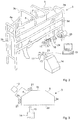
- With reference next to
Fig. 2 a further embodiment of the present invention will be described. The arrangement for determining teat positions is here implemented in a voluntary milking system orstation 3 comprising an enclosure having aninlet gate 4 and anoutlet gate 5, which are both capable of being opened automatically. The front end of the milkingstation 3 is denoted by 3a, the back end is denoted by 3b, the sides are denoted by 3c and 3d. - The milking
station 3 comprises further an automatic milking machine (not explicitly illustrated) including teat cups 11 connected to an end unit by means of milk lines (only the portions attached to the teat cups 11 are shown inFig. 2 ). The milking station further includes a milkingrobot 14 having amovable robot arm 15 provided with a gripper. The milkingrobot 14 is arranged to automatically apply the teat cups 11 of the milking machine to the teats of a milkinganimal 8 present in the milkingstation 3 prior to milking. InFig. 2 three of the teat cups 11 are arranged in a teat cup rack ormagazine 16, whereas the fourth one is held by the gripper of therobot arm 15. Typically, a teat cleaning device including e.g. ateat cleaning cup 24 or brushes 25 may be provided for cleaning the teats of the milkinganimal 8 prior to milking. - Further, the milking
station 3 comprises an identification device (not illustrated) provided to identify a milking animal approaching the milkingstation 3, and acontrol device 19, which is responsible for controlling of the milking system, which inter alia includes the initiation of various activities in connection with the milking such as e.g. opening and closing of thegates handling device 14 - The arrangement for determining teat positions comprises a three-dimensional time-of-flight
real time camera 21 for repeatedly recording three-dimensional images of the udder of the milking animal in real time. Image processing means 22 of e.g. thecontrol device 19 detects repeatedly the teats of the milking animal and determines their positions in all three spatial dimensions based on the repeatedly recorded three-dimensional images of the udder of the milkinganimal 8. - The three-
dimensional camera 21 is mounted on themovable robot arm 15 of the milkingrobot 14 and thecontrol device 19 is thus provided for determining the positions of the teats of the milking animal in all three spatial dimensions relative themovable robot arm 15. - The inventive arrangement may further be arranged for determination of the positions and orientations of the teat cups 11, the
teat cleaning cup 24, and thebrushes 25. -
Fig. 3 illustrates a further embodiment of the invention wherein the arrangement for determining teat positions is implemented in a voluntary milking system of the above kind. Here, two three-dimensional cameras 21 are mounted in fixed positions with respect to the milkingstation 3. One three-dimensional camera 21 is arranged to record three-dimensional images of the udder of a milking animal from behind and one three-dimensional camera 21 is arranged to record three-dimensional images of the udder of the milking animal from a side. - The image processing means of the
control device 19, to which the three-dimensional cameras 21 are operatively connected, is provided for determining the positions of the teats of the milking animal in all three spatial dimensions relative the milkingstation 3 based on three-dimensional images recorded by the two three-dimensional cameras. - It shall be appreciated that the inventive arrangement for determining teat positions of the present invention may be implemented in virtually any kind of milking system where the teat positions need to be found automatically.
- There are many prior art techniques for determining the identities of milking animals, however, many of them being complex or requiring the providing of each of the milking animals to be identified with a transducer or tag.
-
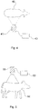
Fig. 4 shows a novel arrangement for determining the identity of a milking animal based on the above three-dimensional measurement concept. A three-dimensional camera 41, preferably a three-dimensional time-of-flight camera, is directed towards the milkinganimal 42, or a part thereof, wherein the three-dimensional camera is arranged to record a three-dimensional image of the milking animal, or the part thereof. Animage processing device 43 is provided for digitally processing the recorded three-dimensional image and for determining the identity of the milking animal among a group of milking animals based on comparisons between the digitally processed three-dimensional image and (i) physical parameters characteristic for each milking animal of the group of milking animals or (ii) previously recorded digitally processed three-dimensional images of each milking animal of the group of milking animals. - Preferably, the three-
dimensional camera 41 is provided to record the three-dimensional image to be digitally processed as a three-dimensional image of the udder/teats of the milkinganimal 42, preferably from a position below the udder of the milkinganimal 42. Alternatively, the three-dimensional camera 41 is positioned elsewhere and/or oriented differently. - The physical parameters characteristic for the milking animals can be found by detailed analysis of digital images of the milking animals, e.g. as recorded by the three-
dimensional camera 41. - The above arrangement is less complicated than prior art systems. The milking animals have not to be provided with transducers or tags. A three-dimensional camera, which may already be provided for other purposes such as e.g. the above determination of teat positions, can be used for the identification. Thus, less equipment is needed for the achievement of a certain number of functions of the milking system.
- Further, the time-of-flight based three-dimensional imaging technology provides for rapid and direct identification of milking animals.
- Still further, the arrangement may be provided for detecting damaged or swollen teats or any other abnormal teat condition and to alert a dairy farmer of such condition.
- It shall be appreciated that the above arrangement may be implemented in a milking system or a milking stall, but alternatively it may be implemented in a feeding station, at a gate arrangement, or elsewhere at a dairy farm.
- In the prior art the weights of milking animals are typically determined by weighing devices, onto which the milking animals are led or guided. Such devices, however, are bulky and costly.
-
Fig. 5 shows a novel arrangement for determining the weight of a milkinganimal 52 based on the above three-dimensional measurement concept. A three-dimensional camera 51, preferably a three-dimensional time-of-flight camera, is directed towards the milkinganimal 52, wherein the three-dimensional camera is provided to record a three-dimensional image of the milking animal. Animage processing device 53 is provided for digitally processing the recorded three-dimensional image and for determining the weight of the milking animal based on the digitally processed three-dimensional image and a table which correlates dimensions or volumes with weights for the species or breed, to which the milking animal belongs. - Preferably, the three-
dimensional camera 51 is located above the milkinganimal 52 and is directed downwards towards the milkinganimal 52. The camera may be located at an angle α with respect to a vertical plane parallel with a longitudinal direction of the milkinganimal 52. - In one version, the arrangement comprises a second three-dimensional camera (not illustrated) directed towards the milking animal, wherein the three-dimensional cameras are provided to record three-dimensional images of the milking animal at different view angles, wherein the
image processing device 53 is provided for digitally processing the recorded three-dimensional images and for determining the weight of the milking animal based on the digitally processed three-dimensional images and the table which correlates dimensions with weights for the breed, to which the milking animal belongs. - Alternatively, the three-dimensional images of the milking animal at different view angles may be recorded by a single three-dimensional camera, which is movable between at least two positions. For instance, the three-dimensional camera may be movable between two positions located at each side of a vertical plane parallel with a longitudinal axis of the animal.
- The above arrangement is less bulky than a conventional weighing device and the arrangement may be used for other purposes as well. The arrangement may be implemented at any location of a dairy farm.
- It shall be noted that the arrangement of
Fig. 4 may be arranged for determining or calculating a body score index (BSI), which can be used as a parameter related to the health of the milking animal. While any of the above described camera locations may be used for body score index determinations, it seems like that locating the three-dimensional camera 51 above the milkinganimal 52 at an angle α with respect to a vertical plane parallel with a longitudinal direction of the milkinganimal 52 and directing the camera diagonally downwards towards the milkinganimal 52 is a preferred option. - By placing the camera so that the important body parts for body score index can be exposed and then making a computer "cut out" of the model, a calculation of the volume can be made. From a reference value for each milking animal stored in a database, a current body score index can be determined.
- It shall further be noted that the arrangements of
Figs. 4 and 5 may be applied to other animals than milking animals. - It shall be appreciated by a person skilled in the art that various features of the above embodiments can be combined to form yet further embodiments. Particularly, a multifunctional arrangement may be provided for determining teat positions, for identifying animals, and for weighing animals.
Claims (14)
- An arrangement provided for determining positions of the teats of a milking animal (8) in a milking system comprising a milking stall (5) for housing the milking animal during milking, a movable robot arm (15) for automatically attaching teat cups (11) to the teats of the milking animal (8) in the milking stall (5), and a control device (19) for controlling the movement of said robot arm (15) based on determined positions of the teats of the milking animal (8), wherein said arrangement comprises:- a three-dimensional camera (21) directable towards the udder of the milking animal in the milking stall (5), wherein the three-dimensional camera is provided to repeatedly record three-dimensional images of the udder of the milking animal in real time; and- image processing means provided for repeatedly detecting the teats of the milking animal and determining their positions in all three spatial dimensions based on said repeatedly recorded three-dimensional images, and- said arrangement is provided for determining positions of the teats of the milking animal in a rotary milking system (3); characterized in that- said three-dimensional camera (21) is directable towards teat cups (11) located in a magazine, wherein the three-dimensional camera is provided to repeatedly record three-dimensional images of the teat cups in real time; and- the image processing means is provided for repeatedly detecting the teats cups and determining their positions in all three spatial dimensions based on said repeatedly recorded three-dimensional images of the teat cups located in the magazine; and wherein the arrangement comprises:- a control device for holding or receiving information of the position of each of the teats of the milking animal relative the other teats of the milking animal and for controlling said robot arm to move to an obscured teat of the milking animal based on said information of the position of each of the teats of the milking animal relative the other teats of the milking animal and on the determined position of a repeatedly detected teat of the milking animal, which is not obscured.
- The arrangement of claim 1 wherein said three-dimensional camera is a three-dimensional time-of-flight camera.
- The arrangement of claim 1 or 2 wherein said image processing means is provided to form a three-dimensional surface representation of a portion of the milking animal from the three-dimensional image of the milking animal; to analyze the surface of the three-dimensional surface representation; and to determine the position of the teats of the milking animal based on the analysis of the surface of the three-dimensional surface representation.
- The arrangement of claim 3 wherein said analysis includes the comparison of elevations of portions of said surface of the three-dimensional surface representation located adjacent one another.
- The arrangement of claim 3 wherein said analysis includes the comparison of elevation gradients of said surface of the three-dimensional surface representation with reference gradients.
- The arrangement of any of claims 1-5 wherein- said three-dimensional camera is directable towards a leg or an outer contour of the milking animal in the milking stall, wherein the three-dimensional camera is provided to record a three-dimensional image in real time of the leg or the outer contour of the milking animal; and- the image processing means is provided for detecting the milking animal and determining its position in at least one spatial dimension based on said recorded three-dimensional image of the leg or the outer contour of the milking animal.
- The arrangement of claim 6 wherein said leg or outer contour of the milking animal includes a back leg of the milking animal.
- The arrangement of any of claims 1-7 wherein said arrangement is a multifunctional detection system further provided for detecting any of the following: (i) presence of a milking animal in a milking stall, (ii) the behavior of a milking animal, (iii) the activity of a milking animal, (iv) the body shape of a milking animal, (v) an incorrect teat cup attachment, (vi) a teat cup kick-off, (vii) presence of an obstacle in the working area of the robot arm, (viii) a parameter related to the operation of the robot arm, and (ix) a parameter related to the operation of the three-dimensional camera.
- The arrangement of any of claims 1-8 wherein- said three-dimensional camera is directable towards the milking animal, or a part thereof, wherein the three-dimensional camera is provided to record a three-dimensional image of the milking animal, or the part thereof; and- the image processing means is provided for digitally processing the recorded three-dimensional image and for determining the identity of the milking animal based on comparisons between the digitally processed three-dimensional image and (i) physical parameters characteristic for each of a group of milking animals or (ii) previously recorded digitally processed three-dimensional images of each of a group of milking animals.
- The arrangement of any of claims 1-9 wherein- said three-dimensional camera is directable towards the milking animal, wherein the three-dimensional camera is provided to record a further three-dimensional image of the milking animal; and- the image processing means is provided for digitally processing the further recorded three-dimensional image and for determining the weight of the milking animal based on the digitally processed three-dimensional image and a table which correlates dimensions or volumes with weights for the species or breed, to which the milking animal belongs.
- The arrangement of claim 10 wherein- said arrangement comprises a second three-dimensional camera directable towards the milking animal, wherein the three-dimensional cameras are provided to record three-dimensional images of the milking animal at different view angles; and- the image processing means is provided for digitally processing the recorded three-dimensional images and for determining the weight of the milking animal based on the digitally processed three-dimensional images and the table which correlates dimensions with weights for the breed, to which the milking animal belongs.
- A milking system comprising a milking stall for housing the milking animal during milking; a movable robot arm for automatically attaching teat cups to the teats of a milking animal in the milking stall; a control device for controlling the movement of said robot arm based on determined positions of the teats of the milking animal; and the arrangement of any of claims 1-11.
- A method for determining positions of the teats of a milking animal (8) in a milking system comprising a milking stall (5) for housing the milking animal during milking, a movable robot arm (15) for automatically attaching teat cups (11) to the teats of the milking animal in the milking stall, and a control device (19) for controlling the movement of said robot arm based on determined positions of the teats of the milking animal, said method comprising the steps of:- directing a three-dimensional camera (21) towards the teats of the milking animal (8) in the milking stall (5);- repeatedly recording three-dimensional images of the teats of the milking animal in real time by said three-dimensional camera; and- repeatedly detecting the teats of the milking animal and determining their positions in all three spatial dimensions based on said repeatedly recorded three-dimensional images, and- determining positions of the teats of the milking animal in a rotary milking system; and being characterized by the steps of- directing said three-dimensional camera towards teat cups (11) located in a magazine;- repeatedly recording three-dimensional images of the teat cups in real time by said three-dimensional camera;- repeatedly detecting the teats cups (11) and determining their positions in all three spatial dimensions based on said repeatedly recorded three-dimensional images of the teat cups located in the magazine; and- holding or receiving information of the position of each of the teats of the milking animal relative the other teats of the milking animal and for controlling said robot arm to move to an obscured teat of the milking animal based on said information of the position of each of the teats of the milking animal relative the other teats of the milking animal and on the determined position of a repeatedly detected teat of the milking animal, which is not obscured.
- The method of claim 13 wherein said three-dimensional camera directable towards the teats of the milking animal in the milking stall is a three-dimensional time-of-flight camera.
Priority Applications (1)
| Application Number | Priority Date | Filing Date | Title |
|---|---|---|---|
| EP19163723.0A EP3520605B1 (en) | 2008-01-22 | 2009-01-16 | Arrangement and method for determining a weight of an animal |
Applications Claiming Priority (2)
| Application Number | Priority Date | Filing Date | Title |
|---|---|---|---|
| SE0800149 | 2008-01-22 | ||
| PCT/SE2009/050040 WO2009093965A1 (en) | 2008-01-22 | 2009-01-16 | Arrangement and method for determining positions of the teats of a milking animal |
Related Child Applications (2)
| Application Number | Title | Priority Date | Filing Date |
|---|---|---|---|
| EP19163723.0A Division EP3520605B1 (en) | 2008-01-22 | 2009-01-16 | Arrangement and method for determining a weight of an animal |
| EP19163723.0A Division-Into EP3520605B1 (en) | 2008-01-22 | 2009-01-16 | Arrangement and method for determining a weight of an animal |
Publications (3)
| Publication Number | Publication Date |
|---|---|
| EP2244556A1 EP2244556A1 (en) | 2010-11-03 |
| EP2244556A4 EP2244556A4 (en) | 2017-06-28 |
| EP2244556B1 true EP2244556B1 (en) | 2019-07-24 |
Family
ID=40901336
Family Applications (3)
| Application Number | Title | Priority Date | Filing Date |
|---|---|---|---|
| EP19163723.0A Active EP3520605B1 (en) | 2008-01-22 | 2009-01-16 | Arrangement and method for determining a weight of an animal |
| EP09704002.6A Active EP2244556B1 (en) | 2008-01-22 | 2009-01-16 | Arrangement and method for determining positions of the teats of a milking animal |
| EP09703583.6A Active EP2244555B1 (en) | 2008-01-22 | 2009-01-16 | Arrangement and method for determining the position of an animal |
Family Applications Before (1)
| Application Number | Title | Priority Date | Filing Date |
|---|---|---|---|
| EP19163723.0A Active EP3520605B1 (en) | 2008-01-22 | 2009-01-16 | Arrangement and method for determining a weight of an animal |
Family Applications After (1)
| Application Number | Title | Priority Date | Filing Date |
|---|---|---|---|
| EP09703583.6A Active EP2244555B1 (en) | 2008-01-22 | 2009-01-16 | Arrangement and method for determining the position of an animal |
Country Status (6)
| Country | Link |
|---|---|
| US (2) | US9635834B2 (en) |
| EP (3) | EP3520605B1 (en) |
| AU (1) | AU2009206799A1 (en) |
| CA (1) | CA2711388C (en) |
| NZ (3) | NZ609288A (en) |
| WO (2) | WO2009093965A1 (en) |
Families Citing this family (59)
| Publication number | Priority date | Publication date | Assignee | Title |
|---|---|---|---|---|
| KR100916638B1 (en) * | 2007-08-02 | 2009-09-08 | 인하대학교 산학협력단 | Device for Computing the Excavated Soil Volume Using Structured Light Vision System and Method thereof |
| NZ566631A (en) * | 2008-03-11 | 2011-04-29 | Scott Milktech Ltd | A robotic milking system and a method of attaching milking cups |
| US8281746B2 (en) * | 2008-03-27 | 2012-10-09 | Delaval Holding Ab | Positioning of teat cups |
| WO2010139602A2 (en) * | 2009-06-05 | 2010-12-09 | Delaval Holding Ab | Safety system |
| WO2011031210A1 (en) * | 2009-09-08 | 2011-03-17 | Delaval Holding Ab | Arrangement and method for determining positions of the teats of a milking animal |
| NL1037611C2 (en) * | 2010-01-05 | 2011-07-06 | Lely Patent Nv | MILK SYSTEM AND METHOD FOR MILKING A HERD MILK ANIMALS. |
| GB2480634A (en) | 2010-05-25 | 2011-11-30 | Delaval Holding Ab | Control and monitoring system for a rotating dairy platform |
| US9161511B2 (en) | 2010-07-06 | 2015-10-20 | Technologies Holdings Corp. | Automated rotary milking system |
| US8800487B2 (en) | 2010-08-31 | 2014-08-12 | Technologies Holdings Corp. | System and method for controlling the position of a robot carriage based on the position of a milking stall of an adjacent rotary milking platform |
| US10111401B2 (en) | 2010-08-31 | 2018-10-30 | Technologies Holdings Corp. | System and method for determining whether to operate a robot in conjunction with a rotary parlor |
| US9149018B2 (en) | 2010-08-31 | 2015-10-06 | Technologies Holdings Corp. | System and method for determining whether to operate a robot in conjunction with a rotary milking platform based on detection of a milking claw |
| US8707905B2 (en) | 2010-08-31 | 2014-04-29 | Technologies Holdings Corp. | Automated system for applying disinfectant to the teats of dairy livestock |
| GB2486913A (en) * | 2010-12-30 | 2012-07-04 | Delaval Holding Ab | Control and monitoring system for an animal installation |
| WO2012123948A1 (en) | 2011-03-17 | 2012-09-20 | Mirobot Ltd. | System and method for three dimensional teat modeling for use with a milking system |
| EP2685810B1 (en) | 2011-03-17 | 2020-09-09 | Mirobot Ltd. | Human assisted milking robot and method |
| GB2489668A (en) * | 2011-03-28 | 2012-10-10 | Delaval Holding Ab | A method and apparatus for locating the teats of an animal |
| US9161512B2 (en) | 2011-04-28 | 2015-10-20 | Technologies Holdings Corp. | Milking box with robotic attacher comprising an arm that pivots, rotates, and grips |
| US8671885B2 (en) | 2011-04-28 | 2014-03-18 | Technologies Holdings Corp. | Vision system for robotic attacher |
| US9258975B2 (en) | 2011-04-28 | 2016-02-16 | Technologies Holdings Corp. | Milking box with robotic attacher and vision system |
| US9265227B2 (en) | 2011-04-28 | 2016-02-23 | Technologies Holdings Corp. | System and method for improved attachment of a cup to a dairy animal |
| US10357015B2 (en) | 2011-04-28 | 2019-07-23 | Technologies Holdings Corp. | Robotic arm with double grabber and method of operation |
| US8885891B2 (en) | 2011-04-28 | 2014-11-11 | Technologies Holdings Corp. | System and method for analyzing data captured by a three-dimensional camera |
| US9107378B2 (en) | 2011-04-28 | 2015-08-18 | Technologies Holdings Corp. | Milking box with robotic attacher |
| US9043988B2 (en) | 2011-04-28 | 2015-06-02 | Technologies Holdings Corp. | Milking box with storage area for teat cups |
| DK3305069T3 (en) * | 2011-04-28 | 2021-08-30 | Technologies Holdings Corp | AUTOMATIC SYSTEM FOR APPLICATION OF DISINFECTANT TO DUTY OF MILK ANIMALS |
| US8683946B2 (en) | 2011-04-28 | 2014-04-01 | Technologies Holdings Corp. | System and method of attaching cups to a dairy animal |
| US9681634B2 (en) * | 2011-04-28 | 2017-06-20 | Technologies Holdings Corp. | System and method to determine a teat position using edge detection in rear images of a livestock from two cameras |
| US9357744B2 (en) * | 2011-04-28 | 2016-06-07 | Technologies Holdings Corp. | Cleaning system for a milking box stall |
| US9058657B2 (en) | 2011-04-28 | 2015-06-16 | Technologies Holdings Corp. | System and method for filtering data captured by a 3D camera |
| US9215861B2 (en) | 2011-04-28 | 2015-12-22 | Technologies Holdings Corp. | Milking box with robotic attacher and backplane for tracking movements of a dairy animal |
| US9049843B2 (en) | 2011-04-28 | 2015-06-09 | Technologies Holdings Corp. | Milking box with a robotic attacher having a three-dimensional range of motion |
| US8746176B2 (en) | 2011-04-28 | 2014-06-10 | Technologies Holdings Corp. | System and method of attaching a cup to a dairy animal according to a sequence |
| US8903129B2 (en) | 2011-04-28 | 2014-12-02 | Technologies Holdings Corp. | System and method for filtering data captured by a 2D camera |
| US9107379B2 (en) | 2011-04-28 | 2015-08-18 | Technologies Holdings Corp. | Arrangement of milking box stalls |
| US10127446B2 (en) | 2011-04-28 | 2018-11-13 | Technologies Holdings Corp. | System and method for filtering data captured by a 2D camera |
| NL1038793C2 (en) * | 2011-05-03 | 2012-11-06 | Dirk Hendrik Martin Ruiter | MILK INSTALLATION. |
| AU2012346585B2 (en) * | 2011-12-02 | 2017-01-12 | Delaval Holding Ab | Camera cleaning system and method and rotary milking system |
| WO2013170129A1 (en) * | 2012-05-10 | 2013-11-14 | President And Fellows Of Harvard College | A system and method for automatically discovering, characterizing, classifying and semi-automatically labeling animal behavior and quantitative phenotyping of behaviors in animals |
| EP2858481B1 (en) * | 2012-06-12 | 2020-01-22 | DeLaval Holding AB | Arrangement and method for a milking system |
| EP2884835B1 (en) * | 2012-07-20 | 2018-10-24 | DeLaval Holding AB | A rotary milking parlour and a method for such a rotary milking parlour |
| SE1550114A1 (en) * | 2012-07-20 | 2015-02-04 | Lely Patent Nv | Milking arrangement |
| NL2009464C2 (en) * | 2012-09-14 | 2014-03-18 | Lely Patent Nv | MILK DEVICE. |
| WO2014107134A1 (en) | 2013-01-07 | 2014-07-10 | Delaval Holding Ab | Method for milking system and milking system |
| US20140270395A1 (en) * | 2013-03-15 | 2014-09-18 | Propel lP | Methods and apparatus for determining information about objects from object images |
| DE202013002484U1 (en) * | 2013-03-15 | 2014-06-17 | Csb-System Ag | Apparatus for volumetric measurement of an ante-mortem object |
| EP2881757A1 (en) | 2013-12-05 | 2015-06-10 | DeLaval Holding AB | Time-of-flight camera system, robot milking system comprising a time-of-flight camera system and method of operating a time-of-flight camera system |
| CN106572646B (en) | 2014-08-21 | 2020-05-12 | 利拉伐控股有限公司 | Method and device for performing teat related operations in a rotary milking system and rotary milking system |
| DE102015112308A1 (en) * | 2015-07-28 | 2017-02-02 | Gea Farm Technologies Gmbh | Method and device for automatically applying milking cups to teats of a dairy animal |
| NL2015326B1 (en) | 2015-08-21 | 2017-03-13 | Lely Patent Nv | Method and device to automatically detect calving. |
| DE102016207291B4 (en) * | 2016-04-28 | 2023-09-21 | Siemens Healthcare Gmbh | Determination of at least one protocol parameter for a contrast-enhanced imaging procedure |
| US10349613B2 (en) * | 2016-08-17 | 2019-07-16 | Technologies Holdings Corp. | Vision system for teat detection |
| US10349615B2 (en) * | 2016-08-17 | 2019-07-16 | Technologies Holdings Corp. | Vision system for teat detection |
| US10499609B2 (en) * | 2016-08-17 | 2019-12-10 | Technologies Holdings Corp. | Vision system for teat detection |
| US10653102B2 (en) * | 2018-01-31 | 2020-05-19 | Technologies Holdings Corp. | Robotic arm |
| WO2020076225A1 (en) * | 2018-10-10 | 2020-04-16 | Delaval Holding Ab | Animal identification using vision techniques |
| US20220215502A1 (en) * | 2019-05-14 | 2022-07-07 | Delaval Holding Ab | System and method for providing a decision basis for controlling a robotic arm, computer program and nonvolatile data carrier |
| EP3968763A1 (en) * | 2019-05-14 | 2022-03-23 | DeLaval Holding AB | System and method for measuring key features of a rotary milking parlor arrangement, computer program and non-volatile data carrier |
| WO2021193816A1 (en) * | 2020-03-26 | 2021-09-30 | Nttテクノクロス株式会社 | Imaging device, imaging method, and program |
| IL302630A (en) * | 2020-11-25 | 2023-07-01 | Identigen Ltd | A system and method for tracing members of an animal population |
Citations (3)
| Publication number | Priority date | Publication date | Assignee | Title |
|---|---|---|---|---|
| WO2003055297A1 (en) * | 2001-12-28 | 2003-07-10 | Idento Electronics B.V. | Method and apparatus for detection of teats |
| EP1523879A2 (en) * | 2003-10-13 | 2005-04-20 | Lely Enterprises AG | An assembly for and a method of feeding and milking animals, and a feed platform suitable for use in such an assembly |
| WO2007104124A1 (en) * | 2006-03-15 | 2007-09-20 | Lmi Technologies Limited | Time of flight teat location system |
Family Cites Families (27)
| Publication number | Priority date | Publication date | Assignee | Title |
|---|---|---|---|---|
| US4745472A (en) * | 1981-03-30 | 1988-05-17 | Applied Genetics International, Inc. | Animal measuring system |
| NL8600076A (en) * | 1986-01-16 | 1987-08-17 | Lely Nv C Van Der | METHOD AND APPARATUS FOR MILKING AN ANIMAL. |
| DE3742867C3 (en) * | 1987-12-17 | 1998-04-09 | Fraunhofer Ges Forschung | Device for joining elements into corresponding receiving elements of an object |
| US5412420A (en) * | 1992-10-26 | 1995-05-02 | Pheno Imaging, Inc. | Three-dimensional phenotypic measuring system for animals |
| IL123930A (en) * | 1995-10-27 | 2001-08-08 | Alfa Laval Agri Ab | Analysis of colour tone in images for use in animal breeding |
| SE9603054D0 (en) * | 1996-08-22 | 1996-08-22 | Tetra Laval Holdings & Finance | An arrangement for and a method of performing an animal-related action |
| NL1006175C2 (en) | 1997-05-30 | 1998-12-01 | Maasland Nv | Device for milking animals. |
| SE9702628D0 (en) * | 1997-07-07 | 1997-07-07 | Alfa Laval Agri Ab | An animal related apparatus |
| NL1006804C2 (en) | 1997-08-20 | 1999-02-23 | Maasland Nv | Sensor device, as well as a method for determining the position of an object, in particular a teat of an animal to be milked. |
| SE9802920L (en) * | 1998-08-31 | 2000-03-01 | Alfa Laval Agri Ab | Device for monitoring an animal-related volume |
| SE9802919L (en) | 1998-08-31 | 2000-03-01 | Alfa Laval Agri Ab | Device and method for monitoring an animal related area |
| US6323942B1 (en) * | 1999-04-30 | 2001-11-27 | Canesta, Inc. | CMOS-compatible three-dimensional image sensor IC |
| KR20020024688A (en) * | 2000-09-26 | 2002-04-01 | 이대원 | Body Weight measurement Device of video processing and method thereof |
| JP2002286421A (en) * | 2001-03-28 | 2002-10-03 | Hideo Minagawa | Apparatus for measuring weight of animal |
| SE0102162D0 (en) * | 2001-06-19 | 2001-06-19 | Delaval Holding Ab | System and method for milking animals |
| NL1020148C2 (en) * | 2002-03-11 | 2003-09-18 | Lely Entpr Ag | Device and assembly for an animal related operation. |
| IL150915A0 (en) * | 2002-07-25 | 2003-02-12 | Vet Tech Ltd | Imaging system and method for body condition evaluation |
| US6974373B2 (en) * | 2002-08-02 | 2005-12-13 | Geissler Technologies, Llc | Apparatus and methods for the volumetric and dimensional measurement of livestock |
| US6729262B2 (en) * | 2002-10-04 | 2004-05-04 | Innovative Automation, Inc. | Live capture automated milking apparatus and method |
| EP1460453B1 (en) | 2003-03-19 | 2007-04-25 | C.R.F. Società Consortile per Azioni | Three-dimension vision system |
| EP1677591B1 (en) * | 2003-10-10 | 2016-01-06 | AB Svenska Mätanalys | Method and device for the monitoring of pigs |
| NL1024934C2 (en) * | 2003-12-03 | 2005-06-07 | Lely Entpr Ag | Device for milking animals and method therefor. |
| NL1024935C2 (en) | 2003-12-03 | 2005-06-06 | Lely Entpr Ag | Device for milking animals. |
| EP1729562A1 (en) | 2004-03-30 | 2006-12-13 | DeLaval Holding AB | Arrangement and method for determining positions of the teats of a milking animal |
| WO2007050012A1 (en) * | 2005-10-24 | 2007-05-03 | Delaval Holding Ab | Arrangement and method for visual detection in a milking system |
| NL1032435C2 (en) | 2006-09-05 | 2008-03-06 | Maasland Nv | Device for automatically milking a dairy animal. |
| US20080273760A1 (en) | 2007-05-04 | 2008-11-06 | Leonard Metcalfe | Method and apparatus for livestock assessment |
-
2009
- 2009-01-16 WO PCT/SE2009/050040 patent/WO2009093965A1/en active Application Filing
- 2009-01-16 US US12/812,633 patent/US9635834B2/en active Active
- 2009-01-16 CA CA2711388A patent/CA2711388C/en active Active
- 2009-01-16 WO PCT/SE2009/050045 patent/WO2009093967A1/en active Application Filing
- 2009-01-16 NZ NZ609288A patent/NZ609288A/en unknown
- 2009-01-16 NZ NZ586160A patent/NZ586160A/en not_active IP Right Cessation
- 2009-01-16 EP EP19163723.0A patent/EP3520605B1/en active Active
- 2009-01-16 EP EP09704002.6A patent/EP2244556B1/en active Active
- 2009-01-16 NZ NZ586159A patent/NZ586159A/en unknown
- 2009-01-16 EP EP09703583.6A patent/EP2244555B1/en active Active
- 2009-01-16 US US12/812,635 patent/US8624744B2/en active Active
- 2009-01-16 AU AU2009206799A patent/AU2009206799A1/en not_active Abandoned
Patent Citations (3)
| Publication number | Priority date | Publication date | Assignee | Title |
|---|---|---|---|---|
| WO2003055297A1 (en) * | 2001-12-28 | 2003-07-10 | Idento Electronics B.V. | Method and apparatus for detection of teats |
| EP1523879A2 (en) * | 2003-10-13 | 2005-04-20 | Lely Enterprises AG | An assembly for and a method of feeding and milking animals, and a feed platform suitable for use in such an assembly |
| WO2007104124A1 (en) * | 2006-03-15 | 2007-09-20 | Lmi Technologies Limited | Time of flight teat location system |
Also Published As
| Publication number | Publication date |
|---|---|
| US20100289649A1 (en) | 2010-11-18 |
| WO2009093965A1 (en) | 2009-07-30 |
| US20100288198A1 (en) | 2010-11-18 |
| US9635834B2 (en) | 2017-05-02 |
| CA2711388A1 (en) | 2009-07-30 |
| NZ586160A (en) | 2013-05-31 |
| EP3520605B1 (en) | 2021-05-19 |
| EP2244555A4 (en) | 2017-05-10 |
| NZ586159A (en) | 2013-04-26 |
| EP3520605A1 (en) | 2019-08-07 |
| EP2244555B1 (en) | 2019-03-06 |
| WO2009093967A1 (en) | 2009-07-30 |
| NZ609288A (en) | 2014-09-26 |
| EP2244556A4 (en) | 2017-06-28 |
| CA2711388C (en) | 2016-08-30 |
| AU2009206799A1 (en) | 2009-07-30 |
| EP2244555A1 (en) | 2010-11-03 |
| US8624744B2 (en) | 2014-01-07 |
| EP2244556A1 (en) | 2010-11-03 |
Similar Documents
| Publication | Publication Date | Title |
|---|---|---|
| EP2244556B1 (en) | Arrangement and method for determining positions of the teats of a milking animal | |
| EP1940218B1 (en) | Arrangement and method for visual detection in a milking system | |
| US9737040B2 (en) | System and method for analyzing data captured by a three-dimensional camera | |
| US10327415B2 (en) | System and method for improved attachment of a cup to a dairy animal | |
| US9058657B2 (en) | System and method for filtering data captured by a 3D camera | |
| US9510553B2 (en) | Arrangement and method for a milking system | |
| WO2010023122A2 (en) | Arrangement and method for determining positions of the teats of a milking animal | |
| US10127446B2 (en) | System and method for filtering data captured by a 2D camera | |
| CA2775395C (en) | Vision system for robotic attacher | |
| WO2010020457A1 (en) | Arrangement and method for controlling a movable robot arm | |
| US9681634B2 (en) | System and method to determine a teat position using edge detection in rear images of a livestock from two cameras | |
| US8903129B2 (en) | System and method for filtering data captured by a 2D camera | |
| CA2849212C (en) | Vision system for robotic attacher | |
| CA2898603C (en) | Vision system for robotic attacher |
Legal Events
| Date | Code | Title | Description |
|---|---|---|---|
| PUAI | Public reference made under article 153(3) epc to a published international application that has entered the european phase |
Free format text: ORIGINAL CODE: 0009012 |
|
| 17P | Request for examination filed |
Effective date: 20100820 |
|
| AK | Designated contracting states |
Kind code of ref document: A1 Designated state(s): AT BE BG CH CY CZ DE DK EE ES FI FR GB GR HR HU IE IS IT LI LT LU LV MC MK MT NL NO PL PT RO SE SI SK TR |
|
| AX | Request for extension of the european patent |
Extension state: AL BA RS |
|
| DAX | Request for extension of the european patent (deleted) | ||
| RA4 | Supplementary search report drawn up and despatched (corrected) |
Effective date: 20170530 |
|
| RIC1 | Information provided on ipc code assigned before grant |
Ipc: G01S 17/10 20060101ALI20170523BHEP Ipc: G01S 17/89 20060101ALI20170523BHEP Ipc: A01J 5/017 20060101AFI20170523BHEP |
|
| STAA | Information on the status of an ep patent application or granted ep patent |
Free format text: STATUS: EXAMINATION IS IN PROGRESS |
|
| 17Q | First examination report despatched |
Effective date: 20180614 |
|
| GRAP | Despatch of communication of intention to grant a patent |
Free format text: ORIGINAL CODE: EPIDOSNIGR1 |
|
| STAA | Information on the status of an ep patent application or granted ep patent |
Free format text: STATUS: GRANT OF PATENT IS INTENDED |
|
| RIC1 | Information provided on ipc code assigned before grant |
Ipc: G01S 17/89 20060101ALI20190128BHEP Ipc: A01J 5/017 20060101AFI20190128BHEP Ipc: G01S 17/10 20060101ALI20190128BHEP Ipc: A01K 1/12 20060101ALI20190128BHEP |
|
| INTG | Intention to grant announced |
Effective date: 20190220 |
|
| RAP1 | Party data changed (applicant data changed or rights of an application transferred) |
Owner name: DELAVAL HOLDING AB |
|
| RIN1 | Information on inventor provided before grant (corrected) |
Inventor name: HOLMGREN, HANS Inventor name: AXELSSON, THOMAS Inventor name: LIAO, BOHAO |
|
| GRAS | Grant fee paid |
Free format text: ORIGINAL CODE: EPIDOSNIGR3 |
|
| GRAA | (expected) grant |
Free format text: ORIGINAL CODE: 0009210 |
|
| STAA | Information on the status of an ep patent application or granted ep patent |
Free format text: STATUS: THE PATENT HAS BEEN GRANTED |
|
| AK | Designated contracting states |
Kind code of ref document: B1 Designated state(s): AT BE BG CH CY CZ DE DK EE ES FI FR GB GR HR HU IE IS IT LI LT LU LV MC MK MT NL NO PL PT RO SE SI SK TR |
|
| REG | Reference to a national code |
Ref country code: GB Ref legal event code: FG4D |
|
| REG | Reference to a national code |
Ref country code: CH Ref legal event code: EP |
|
| REG | Reference to a national code |
Ref country code: DE Ref legal event code: R096 Ref document number: 602009059207 Country of ref document: DE |
|
| REG | Reference to a national code |
Ref country code: AT Ref legal event code: REF Ref document number: 1157069 Country of ref document: AT Kind code of ref document: T Effective date: 20190815 |
|
| REG | Reference to a national code |
Ref country code: IE Ref legal event code: FG4D |
|
| REG | Reference to a national code |
Ref country code: NL Ref legal event code: FP |
|
| REG | Reference to a national code |
Ref country code: LT Ref legal event code: MG4D |
|
| REG | Reference to a national code |
Ref country code: AT Ref legal event code: MK05 Ref document number: 1157069 Country of ref document: AT Kind code of ref document: T Effective date: 20190724 |
|
| PG25 | Lapsed in a contracting state [announced via postgrant information from national office to epo] |
Ref country code: FI Free format text: LAPSE BECAUSE OF FAILURE TO SUBMIT A TRANSLATION OF THE DESCRIPTION OR TO PAY THE FEE WITHIN THE PRESCRIBED TIME-LIMIT Effective date: 20190724 Ref country code: LT Free format text: LAPSE BECAUSE OF FAILURE TO SUBMIT A TRANSLATION OF THE DESCRIPTION OR TO PAY THE FEE WITHIN THE PRESCRIBED TIME-LIMIT Effective date: 20190724 Ref country code: BG Free format text: LAPSE BECAUSE OF FAILURE TO SUBMIT A TRANSLATION OF THE DESCRIPTION OR TO PAY THE FEE WITHIN THE PRESCRIBED TIME-LIMIT Effective date: 20191024 Ref country code: AT Free format text: LAPSE BECAUSE OF FAILURE TO SUBMIT A TRANSLATION OF THE DESCRIPTION OR TO PAY THE FEE WITHIN THE PRESCRIBED TIME-LIMIT Effective date: 20190724 Ref country code: PT Free format text: LAPSE BECAUSE OF FAILURE TO SUBMIT A TRANSLATION OF THE DESCRIPTION OR TO PAY THE FEE WITHIN THE PRESCRIBED TIME-LIMIT Effective date: 20191125 Ref country code: NO Free format text: LAPSE BECAUSE OF FAILURE TO SUBMIT A TRANSLATION OF THE DESCRIPTION OR TO PAY THE FEE WITHIN THE PRESCRIBED TIME-LIMIT Effective date: 20191024 Ref country code: SE Free format text: LAPSE BECAUSE OF FAILURE TO SUBMIT A TRANSLATION OF THE DESCRIPTION OR TO PAY THE FEE WITHIN THE PRESCRIBED TIME-LIMIT Effective date: 20190724 Ref country code: HR Free format text: LAPSE BECAUSE OF FAILURE TO SUBMIT A TRANSLATION OF THE DESCRIPTION OR TO PAY THE FEE WITHIN THE PRESCRIBED TIME-LIMIT Effective date: 20190724 |
|
| PG25 | Lapsed in a contracting state [announced via postgrant information from national office to epo] |
Ref country code: GR Free format text: LAPSE BECAUSE OF FAILURE TO SUBMIT A TRANSLATION OF THE DESCRIPTION OR TO PAY THE FEE WITHIN THE PRESCRIBED TIME-LIMIT Effective date: 20191025 Ref country code: IS Free format text: LAPSE BECAUSE OF FAILURE TO SUBMIT A TRANSLATION OF THE DESCRIPTION OR TO PAY THE FEE WITHIN THE PRESCRIBED TIME-LIMIT Effective date: 20191124 Ref country code: ES Free format text: LAPSE BECAUSE OF FAILURE TO SUBMIT A TRANSLATION OF THE DESCRIPTION OR TO PAY THE FEE WITHIN THE PRESCRIBED TIME-LIMIT Effective date: 20190724 Ref country code: LV Free format text: LAPSE BECAUSE OF FAILURE TO SUBMIT A TRANSLATION OF THE DESCRIPTION OR TO PAY THE FEE WITHIN THE PRESCRIBED TIME-LIMIT Effective date: 20190724 |
|
| PG25 | Lapsed in a contracting state [announced via postgrant information from national office to epo] |
Ref country code: TR Free format text: LAPSE BECAUSE OF FAILURE TO SUBMIT A TRANSLATION OF THE DESCRIPTION OR TO PAY THE FEE WITHIN THE PRESCRIBED TIME-LIMIT Effective date: 20190724 |
|
| PG25 | Lapsed in a contracting state [announced via postgrant information from national office to epo] |
Ref country code: DK Free format text: LAPSE BECAUSE OF FAILURE TO SUBMIT A TRANSLATION OF THE DESCRIPTION OR TO PAY THE FEE WITHIN THE PRESCRIBED TIME-LIMIT Effective date: 20190724 Ref country code: PL Free format text: LAPSE BECAUSE OF FAILURE TO SUBMIT A TRANSLATION OF THE DESCRIPTION OR TO PAY THE FEE WITHIN THE PRESCRIBED TIME-LIMIT Effective date: 20190724 Ref country code: EE Free format text: LAPSE BECAUSE OF FAILURE TO SUBMIT A TRANSLATION OF THE DESCRIPTION OR TO PAY THE FEE WITHIN THE PRESCRIBED TIME-LIMIT Effective date: 20190724 Ref country code: IT Free format text: LAPSE BECAUSE OF FAILURE TO SUBMIT A TRANSLATION OF THE DESCRIPTION OR TO PAY THE FEE WITHIN THE PRESCRIBED TIME-LIMIT Effective date: 20190724 Ref country code: RO Free format text: LAPSE BECAUSE OF FAILURE TO SUBMIT A TRANSLATION OF THE DESCRIPTION OR TO PAY THE FEE WITHIN THE PRESCRIBED TIME-LIMIT Effective date: 20190724 |
|
| PG25 | Lapsed in a contracting state [announced via postgrant information from national office to epo] |
Ref country code: IS Free format text: LAPSE BECAUSE OF FAILURE TO SUBMIT A TRANSLATION OF THE DESCRIPTION OR TO PAY THE FEE WITHIN THE PRESCRIBED TIME-LIMIT Effective date: 20200224 Ref country code: SK Free format text: LAPSE BECAUSE OF FAILURE TO SUBMIT A TRANSLATION OF THE DESCRIPTION OR TO PAY THE FEE WITHIN THE PRESCRIBED TIME-LIMIT Effective date: 20190724 Ref country code: CZ Free format text: LAPSE BECAUSE OF FAILURE TO SUBMIT A TRANSLATION OF THE DESCRIPTION OR TO PAY THE FEE WITHIN THE PRESCRIBED TIME-LIMIT Effective date: 20190724 |
|
| REG | Reference to a national code |
Ref country code: DE Ref legal event code: R097 Ref document number: 602009059207 Country of ref document: DE |
|
| PLBE | No opposition filed within time limit |
Free format text: ORIGINAL CODE: 0009261 |
|
| STAA | Information on the status of an ep patent application or granted ep patent |
Free format text: STATUS: NO OPPOSITION FILED WITHIN TIME LIMIT |
|
| PG2D | Information on lapse in contracting state deleted |
Ref country code: IS |
|
| 26N | No opposition filed |
Effective date: 20200603 |
|
| PG25 | Lapsed in a contracting state [announced via postgrant information from national office to epo] |
Ref country code: SI Free format text: LAPSE BECAUSE OF FAILURE TO SUBMIT A TRANSLATION OF THE DESCRIPTION OR TO PAY THE FEE WITHIN THE PRESCRIBED TIME-LIMIT Effective date: 20190724 Ref country code: MC Free format text: LAPSE BECAUSE OF FAILURE TO SUBMIT A TRANSLATION OF THE DESCRIPTION OR TO PAY THE FEE WITHIN THE PRESCRIBED TIME-LIMIT Effective date: 20190724 |
|
| REG | Reference to a national code |
Ref country code: CH Ref legal event code: PL |
|
| GBPC | Gb: european patent ceased through non-payment of renewal fee |
Effective date: 20200116 |
|
| REG | Reference to a national code |
Ref country code: BE Ref legal event code: MM Effective date: 20200131 |
|
| PG25 | Lapsed in a contracting state [announced via postgrant information from national office to epo] |
Ref country code: GB Free format text: LAPSE BECAUSE OF NON-PAYMENT OF DUE FEES Effective date: 20200116 Ref country code: FR Free format text: LAPSE BECAUSE OF NON-PAYMENT OF DUE FEES Effective date: 20200131 Ref country code: LU Free format text: LAPSE BECAUSE OF NON-PAYMENT OF DUE FEES Effective date: 20200116 |
|
| PG25 | Lapsed in a contracting state [announced via postgrant information from national office to epo] |
Ref country code: BE Free format text: LAPSE BECAUSE OF NON-PAYMENT OF DUE FEES Effective date: 20200131 Ref country code: CH Free format text: LAPSE BECAUSE OF NON-PAYMENT OF DUE FEES Effective date: 20200131 Ref country code: LI Free format text: LAPSE BECAUSE OF NON-PAYMENT OF DUE FEES Effective date: 20200131 |
|
| PG25 | Lapsed in a contracting state [announced via postgrant information from national office to epo] |
Ref country code: MT Free format text: LAPSE BECAUSE OF FAILURE TO SUBMIT A TRANSLATION OF THE DESCRIPTION OR TO PAY THE FEE WITHIN THE PRESCRIBED TIME-LIMIT Effective date: 20190724 Ref country code: CY Free format text: LAPSE BECAUSE OF FAILURE TO SUBMIT A TRANSLATION OF THE DESCRIPTION OR TO PAY THE FEE WITHIN THE PRESCRIBED TIME-LIMIT Effective date: 20190724 |
|
| PG25 | Lapsed in a contracting state [announced via postgrant information from national office to epo] |
Ref country code: MK Free format text: LAPSE BECAUSE OF FAILURE TO SUBMIT A TRANSLATION OF THE DESCRIPTION OR TO PAY THE FEE WITHIN THE PRESCRIBED TIME-LIMIT Effective date: 20190724 |
|
| PGFP | Annual fee paid to national office [announced via postgrant information from national office to epo] |
Ref country code: DE Payment date: 20230207 Year of fee payment: 15 |
|
| PGFP | Annual fee paid to national office [announced via postgrant information from national office to epo] |
Ref country code: NL Payment date: 20231215 Year of fee payment: 16 Ref country code: IE Payment date: 20231211 Year of fee payment: 16 |