EP2244543A2 - Reconfigurable full authority digital electronic control housing - Google Patents
Reconfigurable full authority digital electronic control housing Download PDFInfo
- Publication number
- EP2244543A2 EP2244543A2 EP10250793A EP10250793A EP2244543A2 EP 2244543 A2 EP2244543 A2 EP 2244543A2 EP 10250793 A EP10250793 A EP 10250793A EP 10250793 A EP10250793 A EP 10250793A EP 2244543 A2 EP2244543 A2 EP 2244543A2
- Authority
- EP
- European Patent Office
- Prior art keywords
- fadec
- housing body
- housing
- stamped
- uniform
- Prior art date
- Legal status (The legal status is an assumption and is not a legal conclusion. Google has not performed a legal analysis and makes no representation as to the accuracy of the status listed.)
- Granted
Links
- 238000000034 method Methods 0.000 claims description 14
- 238000007789 sealing Methods 0.000 claims description 10
- 238000005520 cutting process Methods 0.000 claims description 3
- 238000004519 manufacturing process Methods 0.000 claims description 3
- 230000037237 body shape Effects 0.000 claims description 2
- 239000000463 material Substances 0.000 claims description 2
- 230000008878 coupling Effects 0.000 claims 1
- 238000010168 coupling process Methods 0.000 claims 1
- 238000005859 coupling reaction Methods 0.000 claims 1
- 238000005304 joining Methods 0.000 claims 1
- 238000004891 communication Methods 0.000 description 10
- 230000009977 dual effect Effects 0.000 description 5
- 239000002184 metal Substances 0.000 description 4
- 230000007613 environmental effect Effects 0.000 description 3
- 239000000853 adhesive Substances 0.000 description 1
- 230000001070 adhesive effect Effects 0.000 description 1
- 230000000712 assembly Effects 0.000 description 1
- 238000000429 assembly Methods 0.000 description 1
- 229920006332 epoxy adhesive Polymers 0.000 description 1
- 238000009434 installation Methods 0.000 description 1
- 238000003754 machining Methods 0.000 description 1
- 238000003801 milling Methods 0.000 description 1
- 238000012986 modification Methods 0.000 description 1
- 230000004048 modification Effects 0.000 description 1
Images

Classifications
-
- H—ELECTRICITY
- H05—ELECTRIC TECHNIQUES NOT OTHERWISE PROVIDED FOR
- H05K—PRINTED CIRCUITS; CASINGS OR CONSTRUCTIONAL DETAILS OF ELECTRIC APPARATUS; MANUFACTURE OF ASSEMBLAGES OF ELECTRICAL COMPONENTS
- H05K5/00—Casings, cabinets or drawers for electric apparatus
- H05K5/02—Details
- H05K5/0247—Electrical details of casings, e.g. terminals, passages for cables or wiring
-
- Y—GENERAL TAGGING OF NEW TECHNOLOGICAL DEVELOPMENTS; GENERAL TAGGING OF CROSS-SECTIONAL TECHNOLOGIES SPANNING OVER SEVERAL SECTIONS OF THE IPC; TECHNICAL SUBJECTS COVERED BY FORMER USPC CROSS-REFERENCE ART COLLECTIONS [XRACs] AND DIGESTS
- Y10—TECHNICAL SUBJECTS COVERED BY FORMER USPC
- Y10T—TECHNICAL SUBJECTS COVERED BY FORMER US CLASSIFICATION
- Y10T29/00—Metal working
- Y10T29/49—Method of mechanical manufacture
- Y10T29/49002—Electrical device making
Definitions
- the present disclosure is generally directed to electrical circuitry housing, and more specifically to a housing for a Full Authority Digital Electronic Control system.
- FADEC Full Authority Digital Electronic Controllers
- the FADEC often includes sensitive electronics, which should be protected from environmental elements to prevent unnecessary wear.
- the FADEC housing is made larger to accommodate the two channel circuits as well as an interchannel communication line. To protect the FADEC circuitry from environmental elements, it is sealed within the FADEC housing. Electrical connections extend to outside electronics using standardized connectors.
- FADEC housings are formed from metal blocks that are machined to a desired shape and dimensions.
- the housings also include a machined cover, which can be sealed to an opening in the housing body, created by the machining process, thereby enclosing and protecting the circuitry. Once the FADEC circuitry is installed and the cover is attached to the housing body, the electronic equipment is protected from external elements, such as weather.
- the housing also includes machined, fitted openings for standardized electrical connectors.
- FADEC systems utilize dual channel FADECs.
- a dual channel FADEC could be used in a system where it is desirable to control two engines from a single controller.
- the FADECs are connected together via a control wire or contained within the same housing, depending on physical design and space requirements.
- the dual channel FADECs may also include an interchannel communication device, further increasing the space requirements.
- Each FADEC installation may have different dimensional requirements for the locations of the FADECs. For example one type of aircraft may require two FADECs housed in a single housing, and another type of aircraft may require each FADEC to be housed separately and connected through an external communication line. For this reason, each housing is currently custom built for the intended aircraft.
- a configurable Full Authority Digital Electronic Controller which has a stamped housing body containing a FADEC circuit assembly and a cover which encloses the housing body. At least one electrical connector is mounted on the housing body and electrically coupled to the FADEC circuit assembly.
- FADEC Full Authority Digital Electronic Controller
- the method stamps a sheet of metal into a uniform housing body shape, cuts at least one fitted hole in the uniform housing body, and attaches a standard cover having at least one mounting feature to the uniform housing body.
- FADEC Full Authority Digital Electronic Controller
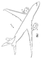
- FIG 1 illustrates an aircraft 10, having multiple engines 12, each of which are controlled by a FADEC 14.
- a single FADEC 14 is used to control each engine 12 in the illustration; however, it is known that multiple engines 12 can be controlled through the utilization of a single multi-channel FADEC. Given their location and purpose, it is desirable to keep the FADEC operational despite environmental factors. While a fixed-wing aircraft 10 is depicted, the system described below is additionally functional in a rotary-wing aircraft, or any other vehicle where digital engine control is desired.
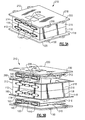
- FIGs 2A and 2B schematically illustrate a single weatherproof FADEC housing and circuit assembly in an assembled ( Figure 2A ) and unassembled ( Figure 2B ) condition.
- a stamped housing body 110 is formed from a single sheet of metal which has been stamped to a uniform depth. Fitted openings 150 for the connectors 140 are located in a side wall 114 of the housing body 110.
- a FADEC circuit assembly 210 is placed in the housing body 110, connectors 140 are placed in the fitted openings 150 and connected to the FADEC circuit assembly 210. Additional punch holes 124 can be placed in the base wall of the housing body 110, to allow for base wall mounted electrical connectors 140, or communication wires for connecting to another FADEC circuit.
- the punch holes 124 can be either fully cut holes where a connector will be placed, or a scored portion of the base wall 122 which can be optionally punched out during assembly. Scoring the punch holes 124 provides additional reconfiguration benefits because scoring allows for connector holes to be readily available should a particular application require them, without requiring other applications to fill a hole should an opening in that location be undesirable.
- the housing body 110 also has a sealing lip 160, which surrounds a primary opening 162 in the housing body 110.
- a cover 120 is sealed to the housing body 110.
- the cover 120 and the housing body 110 both have mounting features 130, which can be used to mount the FADEC to a vehicle body, or to any other appropriate structure.
- the illustrated mounting features 130 are tabs capable of being used in conjunction with fasteners. However, any type of mounting feature 130 could be substituted without altering the disclosed functionality. Alternatively, the mounting features 130 could be located on only one of the housing body 110 and the cover 120.
- the FADEC housing illustrated in Figures 2A and 2B has a rectangular housing body 110 with four side walls 112, 114, 116, 118, each of which adjoins two other side walls 112, 114, 116, 118. Each of the side walls 112, 114, 116, 118 is also connected to a base wall 122. This structure forms the FADEC housing body 110.
- the cover 120 is sealed to each of the four side walls 112, 114, 116, 118 after the FADEC circuit assembly 210 has been installed within the housing using known sealing techniques.
- Alternative shapes having a different number of side walls can also be used depending on the needs of the manufacturer, and the rectangular design is illustrated as an example only.
- FIGs 3A and 3B schematically illustrate another FADEC housing 210 assembled ( Figure 3A ) and unassembled ( Figure 3B ) in a second configuration.
- the second configuration allows for a dual channel FADEC circuit assembly 310 to be assembled within a single housing 210 by stacking two of the FADEC housing bodies 110 illustrated in Figures 2A and 2B , such that their base walls 122 are adjoining.
- the base walls 122 may be connected via an epoxy adhesive, mechanical fasteners, or any other form of mechanical connection.
- each housing body 110 effectively becomes a cover for the other housing body 110.
- the configurable design of the FADEC housings 110, 210 illustrated in Figures 2A, 2B , 3A and 3B allows the FADEC housing 110, 210 to be arranged in multiple configurations, such as the stacked configuration illustrated in Figure 3A and 3B , as well as at configuration 330 in Figure 4C .
- an adjacent configuration could be utilized where two FADEC housings are connected via their side walls 112, 114, 116, 118, 212, 214, 216, 218 or with two mechanically unconnected single FADEC housings which are electrically connected via a communication line.
- Each of the connected housing bodies 110, 210 has fitted holes 150, 250 in which the connectors 140 for the circuit assemblies 310 can be mounted.
- Each FADEC housing body 110, 210 is enclosed via a cover 120, 220 as in Figures 2A and 2B . Additionally illustrated in Figures 3A and 3B are scored holes 226 on each of the covers 120, 220. The scored holes 226 on the covers 120, 220 provide similar benefits to the scored holes 124 described above with reference to Figures 2A and 2B .
- fastener holes may be placed throughout the sealing lip 160, 260 without harming the integrity of the weather tight seal between the cover 120, 220 and the housing body 110, 210.
- the presence of multiple fastener holes allows the housing body 110, 210 to be mounted to a variety of structures without requiring the FADEC housing to be redesigned, or physically altered. This aspect further enhances the reconfigurability of the present design.
- Fitted holes are additionally cut in the side walls thereby forming a housing body 110 with fitted holes 150 for electrical connectors 140.
- the FADEC housing bodies 120 are created using a stamping method, described below, which is quicker and cheaper than the currently used milling methods.
- the stamped and uniform nature of the FADEC housings 110, 210 of this disclosure additionally allows the FADEC housings 110, 210 to be configured in multiple configurations (see Figures 4A-4D ), thereby reducing the need for custom designed configurations.
- the configurable design also allows a manufacturer to purchase identical FADEC housings 110, 210 in bulk and use the FADEC housings 110, 210 in different applications, where each application has different spatial requirements and allowances. This provides a monetary savings as custom designed FADEC housings 110, 210 are no longer required for each project.
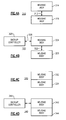
- FIGS 4A-4D illustrate multiple possible configurations for the FADEC housings.
- Each of the housing bodies in the configurations of Figures 4A-4D has a stamped main body portion, and a cover sealed to the main body, as is described with regard to Figures 2A, 2B , 3A, and 3B above. Contained within the housing body is FADEC circuitry, resulting in an assembled controller.
- the first configuration 310, illustrated in Figure 4A has two separate housing bodies 314, 316 and FADEC circuits within each of the housing bodies 314, 316 are coupled together via a communication line 312.
- the communication line 312 is sent through a sealed electrical connector which is mounted in a punch hole 124 (illustrated in Figures 2A and 2B ) in the base wall 122 of the housing body 110, as described with regard to Figures 2A and 2B .
- the second configuration 320 illustrated in Figure 4B , adds a backup controller 329, which is electrically coupled to one of the controllers contained in the housing bodies 324, 326 through the standard electrical connectors 140.
- the housing bodies 324, 326 are arranged in a similar manner to the housings illustrated in Figure 4A .
- the third configuration 330, illustrated in Figure 4C , and the fourth configuration 340, illustrated in Figure 4D each have two housing bodies 332, 334, 342, 344 and are configured a similar manner as the example illustrated in Figures 3A and 3B , with their base walls being physically connected.
- the FADEC circuits housed within the housing bodies 332, 334, 342, 344 are connected via an internal connector wire which passes through aligned punch holes (such as the punch hole 124 illustrated in Figures 2A and 2B ) in the base walls 122 of each housing body.
- the fourth example configuration 340, Figure 4D additionally adds a backup controller 349, which is connected to one of the controllers contained within the housing bodies 342, 344 in the same manner as the second example configuration 320.
- the four illustrated configurations are exemplary only and other configurations could be utilized and still fall within this disclosure.
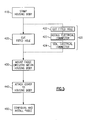
- FIG. 5 An example method for creating the above described stamped FADEC housings is illustrated in Figure 5 .
- the housing body is stamped in a stamp housing body step 410.
- Stamping operates by placing a sheet of metal, or another similar material, which the housing body 110, 210 may be constructed out of, between a post and a hole.
- the post is then pressed into the hole, resulting in a deformed portion of the sheet.
- the deformed portion is an indent in the sheet.
- the indent is shaped corresponding to the shapes of the post and the hole.
- the post and the hole would also be rectangular.
- the stamped indent can then be cut from the sheet to form the FADEC housing body 110, 210.
- each sheet can be used to form a single FADEC housing body 110, 210, resulting in the additional creation of the lip portion 160, 260 encircling the opening 162, 262.
- the housing body has been stamped to the desired shape, holes are cut into the body for the desired electrical connectors and electrical access in the cut fitted holes step 420.
- the electronic circuitry is mounted within the housing body, and connectors are placed in the cut holes and connected to the FADEC circuitry in the mount FADEC circuitry step 430.
- the connectors 140 can be mounted and sealed into the fitted holes during the cut fitted holes step 420. This results in the cut fitted hole step 420 having a series of three substeps of cutting the fitted hole (substep 422), installing the electrical connector (substep 423), and sealing the electrical connector (substep 424).
- the process moves on to the attach cover step 440.
- a cover is mounted to the housing body.
- the cover can then provide a weather tight seal which protects the FADEC circuitry from exposure.
- Multiple assembled FADEC housings can be configured as described above with regards to Figures 4A-4D or in alternative configurations and installed in the configure and install FADEC step 450. If the housing bodies utilized have a sealing lip 160, 260 (as illustrated in Figures 2A, 2B , 3A, and 3B ) fastener holes in the sealing lip 160, 260 can be lined up with fastener holes in the cover 120, 220 or in the structure on which the FADEC will be mounted.
- a fastener can be placed through each of the fastener holes, and the cover 120, 220 may be held to the sealing lip 160, 260, or the housing body may be attached to the aircraft structure. Alternatively the cover may be sealed to the housing body using adhesive or any other known attachment method.
Landscapes
- Engineering & Computer Science (AREA)
- Microelectronics & Electronic Packaging (AREA)
- Casings For Electric Apparatus (AREA)
- Details Of Connecting Devices For Male And Female Coupling (AREA)
Abstract
Description
- The present disclosure is generally directed to electrical circuitry housing, and more specifically to a housing for a Full Authority Digital Electronic Control system.
- Aircraft, as well as other vehicles, typically utilize Full Authority Digital Electronic Controllers (FADEC) to control multiple aspects of the engine operation. In aircraft applications, the FADEC often includes sensitive electronics, which should be protected from environmental elements to prevent unnecessary wear. When a dual channel FADEC (a FADEC which utilizes two channel inputs) is used, the FADEC housing is made larger to accommodate the two channel circuits as well as an interchannel communication line. To protect the FADEC circuitry from environmental elements, it is sealed within the FADEC housing. Electrical connections extend to outside electronics using standardized connectors.
- Currently, FADEC housings are formed from metal blocks that are machined to a desired shape and dimensions. The housings also include a machined cover, which can be sealed to an opening in the housing body, created by the machining process, thereby enclosing and protecting the circuitry. Once the FADEC circuitry is installed and the cover is attached to the housing body, the electronic equipment is protected from external elements, such as weather. The housing also includes machined, fitted openings for standardized electrical connectors.
- Some FADEC systems utilize dual channel FADECs. For example, a dual channel FADEC could be used in a system where it is desirable to control two engines from a single controller. In such a system the FADECs are connected together via a control wire or contained within the same housing, depending on physical design and space requirements. The dual channel FADECs may also include an interchannel communication device, further increasing the space requirements.
- Each FADEC installation may have different dimensional requirements for the locations of the FADECs. For example one type of aircraft may require two FADECs housed in a single housing, and another type of aircraft may require each FADEC to be housed separately and connected through an external communication line. For this reason, each housing is currently custom built for the intended aircraft.
- Disclosed is a configurable Full Authority Digital Electronic Controller (FADEC) which has a stamped housing body containing a FADEC circuit assembly and a cover which encloses the housing body. At least one electrical connector is mounted on the housing body and electrically coupled to the FADEC circuit assembly.
- Additionally disclosed is a method for manufacturing a configurable Full Authority Digital Electronic Controller (FADEC) housing. The method stamps a sheet of metal into a uniform housing body shape, cuts at least one fitted hole in the uniform housing body, and attaches a standard cover having at least one mounting feature to the uniform housing body.
- These and other features of the present invention can be best understood from the following specification and drawings, the following of which is a brief description.
-
-
Figure 1 is an example aircraft using a FADEC to control engine operation. -
Figure 2A is an example configuration of a FADEC housing constructed using a stamped housing body. -
Figure 2B is an exploded view of the example ofFigure 2A . -
Figure 3A is a second example configuration of a FADEC housing constructed using a stamped housing body. -
Figure 3B is an exploded view of the example ofFigure 3A . -
Figure 4A is a diagrammatic description of a first possible FADEC housing configuration. -
Figure 4B is a diagrammatic description of a second possible FADEC housing configuration. -
Figure 4C is a diagrammatic description of a third possible FADEC housing configuration. -
Figure 4D is a diagrammatic description of a fourth possible FADEC housing configuration. -
Figure 5 is a schematic illustration of a method for manufacturing a configurable FADEC housing. -
Figure 1 illustrates an aircraft 10, havingmultiple engines 12, each of which are controlled by a FADEC 14. A single FADEC 14 is used to control eachengine 12 in the illustration; however, it is known thatmultiple engines 12 can be controlled through the utilization of a single multi-channel FADEC. Given their location and purpose, it is desirable to keep the FADEC operational despite environmental factors. While a fixed-wing aircraft 10 is depicted, the system described below is additionally functional in a rotary-wing aircraft, or any other vehicle where digital engine control is desired. -
Figures 2A and 2B schematically illustrate a single weatherproof FADEC housing and circuit assembly in an assembled (Figure 2A ) and unassembled (Figure 2B ) condition. A stampedhousing body 110 is formed from a single sheet of metal which has been stamped to a uniform depth. Fittedopenings 150 for theconnectors 140 are located in aside wall 114 of thehousing body 110. AFADEC circuit assembly 210 is placed in thehousing body 110,connectors 140 are placed in the fittedopenings 150 and connected to theFADEC circuit assembly 210.Additional punch holes 124 can be placed in the base wall of thehousing body 110, to allow for base wall mountedelectrical connectors 140, or communication wires for connecting to another FADEC circuit. Thepunch holes 124 can be either fully cut holes where a connector will be placed, or a scored portion of thebase wall 122 which can be optionally punched out during assembly. Scoring thepunch holes 124 provides additional reconfiguration benefits because scoring allows for connector holes to be readily available should a particular application require them, without requiring other applications to fill a hole should an opening in that location be undesirable. - The
housing body 110 also has asealing lip 160, which surrounds aprimary opening 162 in thehousing body 110. Acover 120 is sealed to thehousing body 110. Thecover 120 and thehousing body 110 both have mountingfeatures 130, which can be used to mount the FADEC to a vehicle body, or to any other appropriate structure. The illustratedmounting features 130 are tabs capable of being used in conjunction with fasteners. However, any type ofmounting feature 130 could be substituted without altering the disclosed functionality. Alternatively, themounting features 130 could be located on only one of thehousing body 110 and thecover 120. - The FADEC housing illustrated in
Figures 2A and 2B has arectangular housing body 110 with fourside walls other side walls side walls base wall 122. This structure forms the FADEChousing body 110. Thecover 120 is sealed to each of the fourside walls circuit assembly 210 has been installed within the housing using known sealing techniques. Alternative shapes having a different number of side walls can also be used depending on the needs of the manufacturer, and the rectangular design is illustrated as an example only. -
Figures 3A and 3B schematically illustrate another FADEChousing 210 assembled (Figure 3A ) and unassembled (Figure 3B ) in a second configuration. The second configuration allows for a dual channelFADEC circuit assembly 310 to be assembled within asingle housing 210 by stacking two of the FADEChousing bodies 110 illustrated inFigures 2A and 2B , such that theirbase walls 122 are adjoining. Thebase walls 122 may be connected via an epoxy adhesive, mechanical fasteners, or any other form of mechanical connection. In such a configuration, eachhousing body 110 effectively becomes a cover for theother housing body 110. - The configurable design of the FADEC
housings Figures 2A, 2B ,3A and 3B allows the FADEChousing Figure 3A and 3B , as well as atconfiguration 330 inFigure 4C . Alternatively, an adjacent configuration could be utilized where two FADEC housings are connected via theirside walls housing bodies holes connectors 140 for thecircuit assemblies 310 can be mounted. EachFADEC housing body cover Figures 2A and 2B . Additionally illustrated inFigures 3A and 3B are scoredholes 226 on each of thecovers covers holes 124 described above with reference toFigures 2A and 2B . - Multiple fastener holes may be placed throughout the sealing
lip cover housing body housing body housing body 110 with fittedholes 150 forelectrical connectors 140. - The
FADEC housing bodies 120 are created using a stamping method, described below, which is quicker and cheaper than the currently used milling methods. The stamped and uniform nature of theFADEC housings FADEC housings Figures 4A-4D ), thereby reducing the need for custom designed configurations. The configurable design also allows a manufacturer to purchaseidentical FADEC housings FADEC housings FADEC housings - The disclosed FADEC housing designs can also include interchannel communication devices (not pictured) mounted on an external portion of the
housing body 110. Locating the interchannel communication devices external to the FADEC housing allows for the FADECs to be configured in varying configurations, rather than locking them in a singular configuration for all applications. Furthermore, space is saved within theFADEC housing body 110 as a result of moving the interchannel communication outside of thehousing body 110, reducing the required size of the FADEC housing. -
Figures 4A-4D illustrate multiple possible configurations for the FADEC housings. Each of the housing bodies in the configurations ofFigures 4A-4D has a stamped main body portion, and a cover sealed to the main body, as is described with regard toFigures 2A, 2B ,3A, and 3B above. Contained within the housing body is FADEC circuitry, resulting in an assembled controller. Thefirst configuration 310, illustrated inFigure 4A , has twoseparate housing bodies housing bodies communication line 312. Thecommunication line 312 is sent through a sealed electrical connector which is mounted in a punch hole 124 (illustrated inFigures 2A and 2B ) in thebase wall 122 of thehousing body 110, as described with regard toFigures 2A and 2B . - The
second configuration 320, illustrated inFigure 4B , adds abackup controller 329, which is electrically coupled to one of the controllers contained in thehousing bodies electrical connectors 140. Thehousing bodies Figure 4A . - The
third configuration 330, illustrated inFigure 4C , and thefourth configuration 340, illustrated inFigure 4D , each have twohousing bodies Figures 3A and 3B , with their base walls being physically connected. The FADEC circuits housed within thehousing bodies punch hole 124 illustrated inFigures 2A and 2B ) in thebase walls 122 of each housing body. Thefourth example configuration 340,Figure 4D , additionally adds abackup controller 349, which is connected to one of the controllers contained within thehousing bodies second example configuration 320. The four illustrated configurations are exemplary only and other configurations could be utilized and still fall within this disclosure. - An example method for creating the above described stamped FADEC housings is illustrated in
Figure 5 . Initially the housing body is stamped in a stamphousing body step 410. Stamping operates by placing a sheet of metal, or another similar material, which thehousing body FADEC housing body FADEC housing body lip portion opening - Once the housing body has been stamped to the desired shape, holes are cut into the body for the desired electrical connectors and electrical access in the cut fitted holes step 420. Once the
preparatory steps connectors 140 can be mounted and sealed into the fitted holes during the cut fitted holes step 420. This results in the cut fittedhole step 420 having a series of three substeps of cutting the fitted hole (substep 422), installing the electrical connector (substep 423), and sealing the electrical connector (substep 424). - Once all of the FADEC circuitry has been mounted, the process moves on to the attach
cover step 440. In the attachcover step 440, a cover is mounted to the housing body. The cover can then provide a weather tight seal which protects the FADEC circuitry from exposure. Multiple assembled FADEC housings can be configured as described above with regards toFigures 4A-4D or in alternative configurations and installed in the configure and installFADEC step 450. If the housing bodies utilized have a sealinglip 160, 260 (as illustrated inFigures 2A, 2B ,3A, and 3B ) fastener holes in the sealinglip cover cover lip - Although example embodiments of this invention have been disclosed, a worker of ordinary skill in this art would recognize that certain modifications would come within the scope of this invention. For that reason, the following claims should be studied to determine the true scope and content of this invention.
Claims (15)
- A Full Authority Digital Electronic Controller (FADEC) (14) comprising;
a first stamped housing body (110);
a first FADEC circuit assembly (210) supported within said stamped housing body;
at least one electrical connector (140) mounted to said first stamped housing body and communicatively coupled to said first FADEC circuit assembly; and
a first cover (120) connected to said first stamped housing body. - The FADEC assembly of claim 1, additionally comprising at least one mounting feature (130) for mounting said FADEC assembly to a vehicle body; preferably wherein said mounting feature comprises a tab (130) having a fastener hole; and/or wherein said mounting feature comprises a sealing lip (160) surrounding a main body opening in said first stamped housing body, said sealing lip comprising at least one fastener hole.
- The FADEC assembly of claim 1 or 2, wherein said first stamped housing body (110) comprises at least one hole (150) for mounting said at least one electrical connector; preferably wherein said electrical connector is mounted in said hole at least partially via a weather tight seal.
- The FADEC assembly of claim 1, 2 or 3, wherein said first cover (120) is connected to said first stamped housing body (110) via a weather tight seal.
- The FADEC assembly of claim 1, 2, 3 or 4, further including a second stamped housing body (210), a second FADEC circuit assembly (310) supported within said second stamped housing body, at least one electrical connector (140) mounted to said second stamped housing body and communicatively coupled to said second FADEC circuit assembly, and a second cover (220) connected to said stamped housing body, wherein said second FADEC circuit assembly is electrically connected to said first FADEC circuit assembly via an electrical coupling (312).
- The FADEC assembly of claim 5, further comprising a backup controller (329) electrically connected to at least one of said first FADEC circuit assembly and said second FADEC circuit assembly via said at least one electrical connector (140).
- The FADEC assembly of claim 5 or 6, wherein said first stamped housing body (110) and said second stamped housing body (210) are physically connected, such that a single unified housing body is formed.
- A method for manufacturing a configurable Full Authority Digital Electronic Controller (FADEC) housing (110) comprising the steps of:stamping a sheet of material into at least one uniform housing body shape;cutting at least one fitted hole (150) in said at least one uniform housing body;mounting a FADEC circuit (310) within said at least one uniform housing body; andattaching a cover (120) comprising at least one mounting feature (130) to said at least one uniform housing body, thereby creating an assembled FADEC housing.
- The method of claim 8, wherein said step of cutting at least one fitted hole further comprises sealing an electrical connector (140) in said at least one fitted hole.
- The method of claim 8 or 9, comprising the additional step of electrically connecting a FADEC circuit (310) mounted within a first (110) of said at least one uniform housing bodies to a FADEC circuit (310) mounted within a second (210) of said at least one uniform housing bodies.
- The method of claim 10, comprising the additional step of electrically connecting a backup controller (329) to at least one of the FADEC circuit mounted within said first uniform housing body and the FADEC circuit mounted within said second uniform housing body.
- The method of claim 8 or 9, wherein said cover comprises a second of said at least one uniform housing bodies, said first of said at least one uniform housing bodies comprises at least one mounting feature, and said step of attaching a cover comprises physically joining the at least one mounting feature of the first of the at least one uniform housing bodies to the at least one mounting feature of the second of the at least one uniform housing bodies.
- The method of claim 12, comprising the additional step of electrically connecting a backup controller (349) to at least one of the FADEC circuits mounted within one of said first of said at least one uniform housing bodies and said second of said at least one uniform housing bodies.
- A configurable FADEC housing comprising:a stamped housing body (110) having at least one fitted opening (150) configured to fit an electrical connector (140); anda cover (120) capable of enclosing said housing body.
- The configurable FADEC housing of claim 14, wherein said cover comprises at least one mounting feature (130); and/or wherein said stamped housing body (110) comprises at least one mounting feature (160,130).
Applications Claiming Priority (1)
| Application Number | Priority Date | Filing Date | Title |
|---|---|---|---|
| US17083509P | 2009-04-20 | 2009-04-20 |
Publications (3)
| Publication Number | Publication Date |
|---|---|
| EP2244543A2 true EP2244543A2 (en) | 2010-10-27 |
| EP2244543A3 EP2244543A3 (en) | 2013-10-09 |
| EP2244543B1 EP2244543B1 (en) | 2015-03-04 |
Family
ID=42358637
Family Applications (1)
| Application Number | Title | Priority Date | Filing Date |
|---|---|---|---|
| EP10250793.6A Active EP2244543B1 (en) | 2009-04-20 | 2010-04-20 | Reconfigurable full authority digital electronic control housing |
Country Status (2)
| Country | Link |
|---|---|
| US (1) | US20100263900A1 (en) |
| EP (1) | EP2244543B1 (en) |
Cited By (3)
| Publication number | Priority date | Publication date | Assignee | Title |
|---|---|---|---|---|
| FR2988978A1 (en) * | 2012-03-28 | 2013-10-04 | Safran | FADEC BOX SUPPORT IN COMPOSITE MATERIAL |
| CN107512400A (en) * | 2017-09-04 | 2017-12-26 | 江西洪都航空工业集团有限责任公司 | Certain type tandem two-seater aircraft Full Authority Digital control device distribution mounting structure |
| CN112913340A (en) * | 2018-10-17 | 2021-06-04 | 三星电子株式会社 | Electronic device comprising a housing in which a protective structure is arranged |
Families Citing this family (7)
| Publication number | Priority date | Publication date | Assignee | Title |
|---|---|---|---|---|
| JP6014436B2 (en) * | 2012-09-20 | 2016-10-25 | 株式会社小松製作所 | Inverter |
| TWD161219S (en) * | 2013-04-10 | 2014-06-21 | 星電股份有限公司 | Electrical connector |
| JP2021504942A (en) * | 2017-12-29 | 2021-02-15 | エスゼット ディージェイアイ テクノロジー カンパニー リミテッドSz Dji Technology Co.,Ltd | Centerboard unit and unmanned aerial vehicle |
| US12203411B2 (en) | 2022-03-23 | 2025-01-21 | General Electric Company | Engine controller for a gas turbine engine |
| US11739662B1 (en) | 2022-03-23 | 2023-08-29 | General Electric Company | Engine controller for a gas turbine engine |
| US12158104B2 (en) | 2022-09-30 | 2024-12-03 | General Electric Company | Conformal structure for a gas turbine engine |
| FR3152839A1 (en) * | 2023-09-13 | 2025-03-14 | Safran Aircraft Engines | TURBOMACHINE BLADE |
Family Cites Families (41)
| Publication number | Priority date | Publication date | Assignee | Title |
|---|---|---|---|---|
| US5105262A (en) * | 1988-09-19 | 1992-04-14 | Ford Motor Company | Thick film circuit housing assembly design |
| JP2882143B2 (en) * | 1991-12-10 | 1999-04-12 | 富士電機株式会社 | Internal wiring structure of semiconductor device |
| US6640235B1 (en) * | 1992-08-20 | 2003-10-28 | Intel Corporation | Expandable mass disk drive storage system |
| JPH07297575A (en) * | 1994-04-21 | 1995-11-10 | Mitsubishi Electric Corp | Power module equipment |
| US5736675A (en) * | 1995-09-11 | 1998-04-07 | Rockwell International Corporation | Apparatus for providing a hermetically sealed environment |
| US5703754A (en) * | 1996-02-26 | 1997-12-30 | Delco Electronics Corporation | Fastenerless sealed electronic module |
| US5998738A (en) * | 1996-08-30 | 1999-12-07 | Motorola Inc. | Electronic control module |
| US5872332A (en) * | 1997-06-27 | 1999-02-16 | Delco Electronics Corp. | Molded housing with EMI shield |
| US5977645A (en) * | 1997-06-30 | 1999-11-02 | Sundstrand Corporation | Aircraft secondary power system |
| US6374912B1 (en) * | 1998-12-30 | 2002-04-23 | Lucent Technologies | Deep drawn enclosure with integrated heatsink and fastening details |
| US6256572B1 (en) * | 1999-03-30 | 2001-07-03 | Kelsey-Hayes Company | Remote programming of an ABS electronic control module |
| DE19921928C2 (en) * | 1999-05-12 | 2002-11-14 | Bosch Gmbh Robert | Electric device |
| DE10045728B4 (en) * | 1999-09-17 | 2015-08-20 | Denso Corporation | Housing for an electronic control unit and arrangement of such a housing and an electronic circuit unit |
| US6350949B1 (en) * | 2000-06-23 | 2002-02-26 | Tyco Electronics Corp | Sealed power distribution module |
| US7375973B2 (en) * | 2000-12-29 | 2008-05-20 | Vertu Limited | Casing for a communication device |
| JP4057914B2 (en) * | 2000-12-29 | 2008-03-05 | ベルツ リミテッド | Case |
| US6492590B1 (en) * | 2001-07-13 | 2002-12-10 | Ching Chi Cheng | Liquid-proof enclosure of electrical device |
| US7002084B2 (en) * | 2002-01-16 | 2006-02-21 | Weightech, Inc. | Modular sealed portable digital electronic controller |
| US6676137B2 (en) * | 2002-02-27 | 2004-01-13 | Hewlett-Packard Development Company, L.P. | Snap-on EMI gasket clip and method of sealing a computer chassis from EMI |
| US6836086B1 (en) * | 2002-03-08 | 2004-12-28 | Hamilton Sundstrand Corporation | Controlled starting system for a gas turbine engine |
| US6570089B1 (en) * | 2002-06-18 | 2003-05-27 | Delphi Technologies, Inc. | Automotive electronics control module enclosure |
| US7005573B2 (en) * | 2003-02-13 | 2006-02-28 | Parker-Hannifin Corporation | Composite EMI shield |
| US6943699B2 (en) * | 2003-07-23 | 2005-09-13 | Harris Corporation | Wireless engine monitoring system |
| JP2005080370A (en) * | 2003-08-29 | 2005-03-24 | Auto Network Gijutsu Kenkyusho:Kk | Circuit structure and method for producing waterproof circuit structure |
| US7186912B2 (en) * | 2003-09-26 | 2007-03-06 | Avanex Corporation | Hermetic lid seal by metal pressing for fiber optic module |
| US6977337B1 (en) * | 2004-06-16 | 2005-12-20 | Visteon Global Technologies, Inc. | Electronic assembly packaging |
| US7245497B2 (en) * | 2005-05-17 | 2007-07-17 | Itt Manufacturing Enterprises, Inc. | Modular electronics enclosure |
| JP4331147B2 (en) * | 2005-08-12 | 2009-09-16 | 浜松ホトニクス株式会社 | Photomultiplier tube |
| JP4929659B2 (en) * | 2005-09-26 | 2012-05-09 | 株式会社ジェイテクト | Electronic control device |
| US7448220B2 (en) * | 2005-10-19 | 2008-11-11 | Hamilton Sundstrand Corporation | Torque control for starting system |
| JP4957048B2 (en) * | 2006-03-31 | 2012-06-20 | 株式会社ジェイテクト | Electronic control device |
| US7372701B2 (en) * | 2006-07-27 | 2008-05-13 | Deere & Company | Cantilever mounted electronic module with rigid center backbone |
| US7563992B2 (en) * | 2006-09-20 | 2009-07-21 | Delphi Technologies, Inc. | Electronic enclosure with continuous ground contact surface |
| US7492594B2 (en) * | 2007-05-03 | 2009-02-17 | Hamilton Sundstrand Corporation | Electronic circuit modules cooling |
| US7616448B2 (en) * | 2007-09-14 | 2009-11-10 | Delphi Technologies, Inc. | Wrap-around overmold for electronic assembly |
| TW200915970A (en) * | 2007-09-27 | 2009-04-01 | Sanyo Electric Co | Circuit device, circuit module and outdoor equipment |
| JP4934559B2 (en) * | 2007-09-27 | 2012-05-16 | オンセミコンダクター・トレーディング・リミテッド | Circuit device and manufacturing method thereof |
| TWI402952B (en) * | 2007-09-27 | 2013-07-21 | 三洋電機股份有限公司 | Circuit device and method of manufacturing same |
| JP4557181B2 (en) * | 2007-11-15 | 2010-10-06 | 株式会社デンソー | Electronic control unit |
| US7955133B2 (en) * | 2008-04-23 | 2011-06-07 | Littelfuse, Inc. | Flexible power distribution module |
| US7824189B1 (en) * | 2009-04-15 | 2010-11-02 | Tyco Electronics Corporation | Junction box for photovoltaic modules |
-
2009
- 2009-12-04 US US12/631,358 patent/US20100263900A1/en not_active Abandoned
-
2010
- 2010-04-20 EP EP10250793.6A patent/EP2244543B1/en active Active
Non-Patent Citations (1)
| Title |
|---|
| None |
Cited By (6)
| Publication number | Priority date | Publication date | Assignee | Title |
|---|---|---|---|---|
| FR2988978A1 (en) * | 2012-03-28 | 2013-10-04 | Safran | FADEC BOX SUPPORT IN COMPOSITE MATERIAL |
| US9204566B2 (en) | 2012-03-28 | 2015-12-01 | Safran | Composite material FADEC box support |
| CN107512400A (en) * | 2017-09-04 | 2017-12-26 | 江西洪都航空工业集团有限责任公司 | Certain type tandem two-seater aircraft Full Authority Digital control device distribution mounting structure |
| CN112913340A (en) * | 2018-10-17 | 2021-06-04 | 三星电子株式会社 | Electronic device comprising a housing in which a protective structure is arranged |
| US11456557B2 (en) | 2018-10-17 | 2022-09-27 | Samsung Electronics Co., Ltd. | Electronic device including housing in which protective structure is disposed |
| CN112913340B (en) * | 2018-10-17 | 2022-12-09 | 三星电子株式会社 | Electronic device comprising a housing in which a protective structure is arranged |
Also Published As
| Publication number | Publication date |
|---|---|
| EP2244543B1 (en) | 2015-03-04 |
| US20100263900A1 (en) | 2010-10-21 |
| EP2244543A3 (en) | 2013-10-09 |
Similar Documents
| Publication | Publication Date | Title |
|---|---|---|
| EP2244543B1 (en) | Reconfigurable full authority digital electronic control housing | |
| EP2702645B1 (en) | Header connector assembly | |
| US10159157B2 (en) | Compliant PCB-to-housing fastener | |
| EP1581036A2 (en) | Method of manufacturing a sealed electronic module | |
| JP2006173402A (en) | Electronic circuit device and manufacturing method thereof | |
| DE102013206689A1 (en) | Sensor and method for manufacturing a sensor | |
| EP3381246A1 (en) | Electronic module and method for producing an electronic module having a fluid-tight housing | |
| US7396254B2 (en) | Flexible electrical connector/housing assembly | |
| US20150096800A1 (en) | Electronic Module for Operation in a Transmission | |
| DE102013215227A1 (en) | Encapsulated electronic module with Flexfolienanbindung, especially for a vehicle transmission control module | |
| US6479916B1 (en) | Method and apparatus for mounting electronic motor controls | |
| CN102959703B (en) | Encapsulation for motor vehicles controls module | |
| EP2055155B1 (en) | Control unit for a motor vehicle | |
| JP2019523557A (en) | Circuit board assembly | |
| US20150373867A1 (en) | Electronics housing | |
| EP3370489A1 (en) | Electronic module for an electric motor, in particular a pump unit | |
| DE102007044394B4 (en) | Module for integrated control electronics with simplified design | |
| US20190115686A1 (en) | Sealed electrical plug connector arrangement | |
| EP1469233B1 (en) | Method for forming a gearbox casing for a plurality of engines for motor vehicles, and casing produced by this method | |
| EP3930113B1 (en) | Crimp pin electrical connector | |
| EP1469234B1 (en) | Method for forming a gearbox casing for a plurality of engines for motor vehicles, and forming mould for producing the casing | |
| US20250048578A1 (en) | Printed circuit board for an automation field device | |
| US20210296811A1 (en) | Waterproof and explosion-proof circuit board and electronic valve actuator for flow control applications | |
| US20060268529A1 (en) | Arrangement for electrical and/or mechanical components on a large, flexible foil type conductor area | |
| KR20170087291A (en) | Communication module |
Legal Events
| Date | Code | Title | Description |
|---|---|---|---|
| PUAI | Public reference made under article 153(3) epc to a published international application that has entered the european phase |
Free format text: ORIGINAL CODE: 0009012 |
|
| AK | Designated contracting states |
Kind code of ref document: A2 Designated state(s): AT BE BG CH CY CZ DE DK EE ES FI FR GB GR HR HU IE IS IT LI LT LU LV MC MK MT NL NO PL PT RO SE SI SK SM TR |
|
| AX | Request for extension of the european patent |
Extension state: AL BA ME RS |
|
| PUAL | Search report despatched |
Free format text: ORIGINAL CODE: 0009013 |
|
| AK | Designated contracting states |
Kind code of ref document: A3 Designated state(s): AT BE BG CH CY CZ DE DK EE ES FI FR GB GR HR HU IE IS IT LI LT LU LV MC MK MT NL NO PL PT RO SE SI SK SM TR |
|
| AX | Request for extension of the european patent |
Extension state: AL BA ME RS |
|
| RIC1 | Information provided on ipc code assigned before grant |
Ipc: B60R 16/023 20060101ALI20130903BHEP Ipc: B64D 33/00 20060101ALI20130903BHEP Ipc: H05K 5/02 20060101ALI20130903BHEP Ipc: H05K 5/00 20060101AFI20130903BHEP |
|
| 17P | Request for examination filed |
Effective date: 20140407 |
|
| RBV | Designated contracting states (corrected) |
Designated state(s): AT BE BG CH CY CZ DE DK EE ES FI FR GB GR HR HU IE IS IT LI LT LU LV MC MK MT NL NO PL PT RO SE SI SK SM TR |
|
| REG | Reference to a national code |
Ref country code: DE Ref legal event code: R079 Ref document number: 602010022783 Country of ref document: DE Free format text: PREVIOUS MAIN CLASS: H05K0005000000 Ipc: H05K0005020000 |
|
| GRAP | Despatch of communication of intention to grant a patent |
Free format text: ORIGINAL CODE: EPIDOSNIGR1 |
|
| RIC1 | Information provided on ipc code assigned before grant |
Ipc: H05K 5/02 20060101AFI20140822BHEP |
|
| INTG | Intention to grant announced |
Effective date: 20140924 |
|
| GRAS | Grant fee paid |
Free format text: ORIGINAL CODE: EPIDOSNIGR3 |
|
| GRAA | (expected) grant |
Free format text: ORIGINAL CODE: 0009210 |
|
| AK | Designated contracting states |
Kind code of ref document: B1 Designated state(s): AT BE BG CH CY CZ DE DK EE ES FI FR GB GR HR HU IE IS IT LI LT LU LV MC MK MT NL NO PL PT RO SE SI SK SM TR |
|
| REG | Reference to a national code |
Ref country code: GB Ref legal event code: FG4D |
|
| REG | Reference to a national code |
Ref country code: CH Ref legal event code: EP |
|
| REG | Reference to a national code |
Ref country code: IE Ref legal event code: FG4D |
|
| REG | Reference to a national code |
Ref country code: AT Ref legal event code: REF Ref document number: 714794 Country of ref document: AT Kind code of ref document: T Effective date: 20150415 |
|
| REG | Reference to a national code |
Ref country code: DE Ref legal event code: R096 Ref document number: 602010022783 Country of ref document: DE Effective date: 20150416 |
|
| REG | Reference to a national code |
Ref country code: AT Ref legal event code: MK05 Ref document number: 714794 Country of ref document: AT Kind code of ref document: T Effective date: 20150304 Ref country code: NL Ref legal event code: VDEP Effective date: 20150304 |
|
| PG25 | Lapsed in a contracting state [announced via postgrant information from national office to epo] |
Ref country code: HR Free format text: LAPSE BECAUSE OF FAILURE TO SUBMIT A TRANSLATION OF THE DESCRIPTION OR TO PAY THE FEE WITHIN THE PRESCRIBED TIME-LIMIT Effective date: 20150304 Ref country code: FI Free format text: LAPSE BECAUSE OF FAILURE TO SUBMIT A TRANSLATION OF THE DESCRIPTION OR TO PAY THE FEE WITHIN THE PRESCRIBED TIME-LIMIT Effective date: 20150304 Ref country code: SE Free format text: LAPSE BECAUSE OF FAILURE TO SUBMIT A TRANSLATION OF THE DESCRIPTION OR TO PAY THE FEE WITHIN THE PRESCRIBED TIME-LIMIT Effective date: 20150304 Ref country code: LT Free format text: LAPSE BECAUSE OF FAILURE TO SUBMIT A TRANSLATION OF THE DESCRIPTION OR TO PAY THE FEE WITHIN THE PRESCRIBED TIME-LIMIT Effective date: 20150304 Ref country code: NO Free format text: LAPSE BECAUSE OF FAILURE TO SUBMIT A TRANSLATION OF THE DESCRIPTION OR TO PAY THE FEE WITHIN THE PRESCRIBED TIME-LIMIT Effective date: 20150604 Ref country code: ES Free format text: LAPSE BECAUSE OF FAILURE TO SUBMIT A TRANSLATION OF THE DESCRIPTION OR TO PAY THE FEE WITHIN THE PRESCRIBED TIME-LIMIT Effective date: 20150304 |
|
| REG | Reference to a national code |
Ref country code: LT Ref legal event code: MG4D |
|
| PG25 | Lapsed in a contracting state [announced via postgrant information from national office to epo] |
Ref country code: AT Free format text: LAPSE BECAUSE OF FAILURE TO SUBMIT A TRANSLATION OF THE DESCRIPTION OR TO PAY THE FEE WITHIN THE PRESCRIBED TIME-LIMIT Effective date: 20150304 Ref country code: LV Free format text: LAPSE BECAUSE OF FAILURE TO SUBMIT A TRANSLATION OF THE DESCRIPTION OR TO PAY THE FEE WITHIN THE PRESCRIBED TIME-LIMIT Effective date: 20150304 Ref country code: GR Free format text: LAPSE BECAUSE OF FAILURE TO SUBMIT A TRANSLATION OF THE DESCRIPTION OR TO PAY THE FEE WITHIN THE PRESCRIBED TIME-LIMIT Effective date: 20150605 |
|
| PG25 | Lapsed in a contracting state [announced via postgrant information from national office to epo] |
Ref country code: NL Free format text: LAPSE BECAUSE OF FAILURE TO SUBMIT A TRANSLATION OF THE DESCRIPTION OR TO PAY THE FEE WITHIN THE PRESCRIBED TIME-LIMIT Effective date: 20150304 |
|
| PG25 | Lapsed in a contracting state [announced via postgrant information from national office to epo] |
Ref country code: PT Free format text: LAPSE BECAUSE OF FAILURE TO SUBMIT A TRANSLATION OF THE DESCRIPTION OR TO PAY THE FEE WITHIN THE PRESCRIBED TIME-LIMIT Effective date: 20150706 Ref country code: RO Free format text: LAPSE BECAUSE OF FAILURE TO SUBMIT A TRANSLATION OF THE DESCRIPTION OR TO PAY THE FEE WITHIN THE PRESCRIBED TIME-LIMIT Effective date: 20150304 Ref country code: CZ Free format text: LAPSE BECAUSE OF FAILURE TO SUBMIT A TRANSLATION OF THE DESCRIPTION OR TO PAY THE FEE WITHIN THE PRESCRIBED TIME-LIMIT Effective date: 20150304 Ref country code: EE Free format text: LAPSE BECAUSE OF FAILURE TO SUBMIT A TRANSLATION OF THE DESCRIPTION OR TO PAY THE FEE WITHIN THE PRESCRIBED TIME-LIMIT Effective date: 20150304 Ref country code: SK Free format text: LAPSE BECAUSE OF FAILURE TO SUBMIT A TRANSLATION OF THE DESCRIPTION OR TO PAY THE FEE WITHIN THE PRESCRIBED TIME-LIMIT Effective date: 20150304 |
|
| REG | Reference to a national code |
Ref country code: DE Ref legal event code: R119 Ref document number: 602010022783 Country of ref document: DE |
|
| PG25 | Lapsed in a contracting state [announced via postgrant information from national office to epo] |
Ref country code: MC Free format text: LAPSE BECAUSE OF FAILURE TO SUBMIT A TRANSLATION OF THE DESCRIPTION OR TO PAY THE FEE WITHIN THE PRESCRIBED TIME-LIMIT Effective date: 20150304 Ref country code: IS Free format text: LAPSE BECAUSE OF FAILURE TO SUBMIT A TRANSLATION OF THE DESCRIPTION OR TO PAY THE FEE WITHIN THE PRESCRIBED TIME-LIMIT Effective date: 20150704 Ref country code: PL Free format text: LAPSE BECAUSE OF FAILURE TO SUBMIT A TRANSLATION OF THE DESCRIPTION OR TO PAY THE FEE WITHIN THE PRESCRIBED TIME-LIMIT Effective date: 20150304 |
|
| REG | Reference to a national code |
Ref country code: CH Ref legal event code: PL |
|
| PG25 | Lapsed in a contracting state [announced via postgrant information from national office to epo] |
Ref country code: IT Free format text: LAPSE BECAUSE OF FAILURE TO SUBMIT A TRANSLATION OF THE DESCRIPTION OR TO PAY THE FEE WITHIN THE PRESCRIBED TIME-LIMIT Effective date: 20150304 |
|
| PLBE | No opposition filed within time limit |
Free format text: ORIGINAL CODE: 0009261 |
|
| STAA | Information on the status of an ep patent application or granted ep patent |
Free format text: STATUS: NO OPPOSITION FILED WITHIN TIME LIMIT |
|
| REG | Reference to a national code |
Ref country code: IE Ref legal event code: MM4A |
|
| PG25 | Lapsed in a contracting state [announced via postgrant information from national office to epo] |
Ref country code: LI Free format text: LAPSE BECAUSE OF NON-PAYMENT OF DUE FEES Effective date: 20150430 Ref country code: DK Free format text: LAPSE BECAUSE OF FAILURE TO SUBMIT A TRANSLATION OF THE DESCRIPTION OR TO PAY THE FEE WITHIN THE PRESCRIBED TIME-LIMIT Effective date: 20150304 Ref country code: DE Free format text: LAPSE BECAUSE OF NON-PAYMENT OF DUE FEES Effective date: 20151103 Ref country code: CH Free format text: LAPSE BECAUSE OF NON-PAYMENT OF DUE FEES Effective date: 20150430 |
|
| 26N | No opposition filed |
Effective date: 20151207 |
|
| PG25 | Lapsed in a contracting state [announced via postgrant information from national office to epo] |
Ref country code: SI Free format text: LAPSE BECAUSE OF FAILURE TO SUBMIT A TRANSLATION OF THE DESCRIPTION OR TO PAY THE FEE WITHIN THE PRESCRIBED TIME-LIMIT Effective date: 20150304 |
|
| REG | Reference to a national code |
Ref country code: FR Ref legal event code: PLFP Year of fee payment: 7 |
|
| PG25 | Lapsed in a contracting state [announced via postgrant information from national office to epo] |
Ref country code: IE Free format text: LAPSE BECAUSE OF NON-PAYMENT OF DUE FEES Effective date: 20150420 |
|
| PG25 | Lapsed in a contracting state [announced via postgrant information from national office to epo] |
Ref country code: BE Free format text: LAPSE BECAUSE OF FAILURE TO SUBMIT A TRANSLATION OF THE DESCRIPTION OR TO PAY THE FEE WITHIN THE PRESCRIBED TIME-LIMIT Effective date: 20150304 |
|
| PG25 | Lapsed in a contracting state [announced via postgrant information from national office to epo] |
Ref country code: MT Free format text: LAPSE BECAUSE OF FAILURE TO SUBMIT A TRANSLATION OF THE DESCRIPTION OR TO PAY THE FEE WITHIN THE PRESCRIBED TIME-LIMIT Effective date: 20150304 |
|
| REG | Reference to a national code |
Ref country code: FR Ref legal event code: PLFP Year of fee payment: 8 |
|
| PG25 | Lapsed in a contracting state [announced via postgrant information from national office to epo] |
Ref country code: SM Free format text: LAPSE BECAUSE OF FAILURE TO SUBMIT A TRANSLATION OF THE DESCRIPTION OR TO PAY THE FEE WITHIN THE PRESCRIBED TIME-LIMIT Effective date: 20150304 Ref country code: BG Free format text: LAPSE BECAUSE OF FAILURE TO SUBMIT A TRANSLATION OF THE DESCRIPTION OR TO PAY THE FEE WITHIN THE PRESCRIBED TIME-LIMIT Effective date: 20150304 Ref country code: HU Free format text: LAPSE BECAUSE OF FAILURE TO SUBMIT A TRANSLATION OF THE DESCRIPTION OR TO PAY THE FEE WITHIN THE PRESCRIBED TIME-LIMIT; INVALID AB INITIO Effective date: 20100420 |
|
| PG25 | Lapsed in a contracting state [announced via postgrant information from national office to epo] |
Ref country code: CY Free format text: LAPSE BECAUSE OF FAILURE TO SUBMIT A TRANSLATION OF THE DESCRIPTION OR TO PAY THE FEE WITHIN THE PRESCRIBED TIME-LIMIT Effective date: 20150304 |
|
| PG25 | Lapsed in a contracting state [announced via postgrant information from national office to epo] |
Ref country code: TR Free format text: LAPSE BECAUSE OF FAILURE TO SUBMIT A TRANSLATION OF THE DESCRIPTION OR TO PAY THE FEE WITHIN THE PRESCRIBED TIME-LIMIT Effective date: 20150304 |
|
| PG25 | Lapsed in a contracting state [announced via postgrant information from national office to epo] |
Ref country code: LU Free format text: LAPSE BECAUSE OF NON-PAYMENT OF DUE FEES Effective date: 20150420 |
|
| REG | Reference to a national code |
Ref country code: FR Ref legal event code: PLFP Year of fee payment: 9 |
|
| PG25 | Lapsed in a contracting state [announced via postgrant information from national office to epo] |
Ref country code: MK Free format text: LAPSE BECAUSE OF FAILURE TO SUBMIT A TRANSLATION OF THE DESCRIPTION OR TO PAY THE FEE WITHIN THE PRESCRIBED TIME-LIMIT Effective date: 20150304 |
|
| P01 | Opt-out of the competence of the unified patent court (upc) registered |
Effective date: 20230522 |
|
| PGFP | Annual fee paid to national office [announced via postgrant information from national office to epo] |
Ref country code: FR Payment date: 20250319 Year of fee payment: 16 |
|
| PGFP | Annual fee paid to national office [announced via postgrant information from national office to epo] |
Ref country code: GB Payment date: 20250319 Year of fee payment: 16 |