EP2244387A1 - Method and transmitter for use in secure communication using error correction codes - Google Patents
Method and transmitter for use in secure communication using error correction codes Download PDFInfo
- Publication number
- EP2244387A1 EP2244387A1 EP10160921A EP10160921A EP2244387A1 EP 2244387 A1 EP2244387 A1 EP 2244387A1 EP 10160921 A EP10160921 A EP 10160921A EP 10160921 A EP10160921 A EP 10160921A EP 2244387 A1 EP2244387 A1 EP 2244387A1
- Authority
- EP
- European Patent Office
- Prior art keywords
- nodes
- code
- transmitter
- punctured
- codes
- Prior art date
- Legal status (The legal status is an assumption and is not a legal conclusion. Google has not performed a legal analysis and makes no representation as to the accuracy of the status listed.)
- Withdrawn
Links
Images


Classifications
-
- G—PHYSICS
- G06—COMPUTING; CALCULATING OR COUNTING
- G06F—ELECTRIC DIGITAL DATA PROCESSING
- G06F11/00—Error detection; Error correction; Monitoring
- G06F11/07—Responding to the occurrence of a fault, e.g. fault tolerance
- G06F11/08—Error detection or correction by redundancy in data representation, e.g. by using checking codes
- G06F11/10—Adding special bits or symbols to the coded information, e.g. parity check, casting out 9's or 11's
-
- H—ELECTRICITY
- H03—ELECTRONIC CIRCUITRY
- H03M—CODING; DECODING; CODE CONVERSION IN GENERAL
- H03M13/00—Coding, decoding or code conversion, for error detection or error correction; Coding theory basic assumptions; Coding bounds; Error probability evaluation methods; Channel models; Simulation or testing of codes
- H03M13/03—Error detection or forward error correction by redundancy in data representation, i.e. code words containing more digits than the source words
- H03M13/05—Error detection or forward error correction by redundancy in data representation, i.e. code words containing more digits than the source words using block codes, i.e. a predetermined number of check bits joined to a predetermined number of information bits
- H03M13/11—Error detection or forward error correction by redundancy in data representation, i.e. code words containing more digits than the source words using block codes, i.e. a predetermined number of check bits joined to a predetermined number of information bits using multiple parity bits
- H03M13/1102—Codes on graphs and decoding on graphs, e.g. low-density parity check [LDPC] codes
-
- H—ELECTRICITY
- H03—ELECTRONIC CIRCUITRY
- H03M—CODING; DECODING; CODE CONVERSION IN GENERAL
- H03M13/00—Coding, decoding or code conversion, for error detection or error correction; Coding theory basic assumptions; Coding bounds; Error probability evaluation methods; Channel models; Simulation or testing of codes
- H03M13/03—Error detection or forward error correction by redundancy in data representation, i.e. code words containing more digits than the source words
- H03M13/033—Theoretical methods to calculate these checking codes
-
- H—ELECTRICITY
- H03—ELECTRONIC CIRCUITRY
- H03M—CODING; DECODING; CODE CONVERSION IN GENERAL
- H03M13/00—Coding, decoding or code conversion, for error detection or error correction; Coding theory basic assumptions; Coding bounds; Error probability evaluation methods; Channel models; Simulation or testing of codes
- H03M13/63—Joint error correction and other techniques
- H03M13/635—Error control coding in combination with rate matching
- H03M13/6362—Error control coding in combination with rate matching by puncturing
-
- H—ELECTRICITY
- H04—ELECTRIC COMMUNICATION TECHNIQUE
- H04L—TRANSMISSION OF DIGITAL INFORMATION, e.g. TELEGRAPHIC COMMUNICATION
- H04L9/00—Cryptographic mechanisms or cryptographic arrangements for secret or secure communications; Network security protocols
-
- H—ELECTRICITY
- H04—ELECTRIC COMMUNICATION TECHNIQUE
- H04L—TRANSMISSION OF DIGITAL INFORMATION, e.g. TELEGRAPHIC COMMUNICATION
- H04L63/00—Network architectures or network communication protocols for network security
- H04L63/04—Network architectures or network communication protocols for network security for providing a confidential data exchange among entities communicating through data packet networks
- H04L63/0428—Network architectures or network communication protocols for network security for providing a confidential data exchange among entities communicating through data packet networks wherein the data content is protected, e.g. by encrypting or encapsulating the payload
Definitions
- the present disclosure relates to data communication, and more specifically, to a method and system for use in secure communication using error correcting codes.
- Error correcting codes are conventionally used to provide reliability over a noisy communication channel.
- An error correcting coding scheme transmits extra bits. These extra bits allow the receiver to recover errored bits by deducing the errored bits from the channel observations of the transmitted bits.
- Error correcting codes are conventionally designed to provide as much reliability as possible over a noisy channel. However, this high level of reliability leads to codes which are complex and thus require increased computational resources at the receiver.
- the minimizing and maximizing may steps comprise:
- the method may further comprise marking the chosen k-SR node as a punctured variable node.
- the choosing one of the k-SR nodes using the minimized k-SR criterion may comprise:
- the method may further comprise:
- Choosing using the minimized k-SR criterion may comprise:
- Choosing using the maximized k-SR criterion may use a grouping algorithm.
- the method may further comprise applying the selected code in a transmitter for puncturing a bit stream to be transmitted.
- the method may further comprising selecting a plurality of the codes, storing the plurality of codes in a communication system and selecting one of the plurality of codes for secure communication over a channel in dependence on one or more conditions associated with said channel or attributes of said channel.
- the method may further comprise applying the selected code in a receiver for reconstructing a received bit stream that has been punctured using the selected code.
- the method may be implemented in hardware, software, firmware or some combination thereof.
- a transmitter for a secure transmission system including a reduced security gap encoder (170) arranged to encode a received bit stream using a low density parity check code selected using the method described above for subsequent transmission.
- the reduced security gap encoder is preferably arranged to operate at a physical layer of a protocol stack.
- the transmitter may be arranged to cause disabling of encryption at one or more higher levels in the protocol stack.
- the transmitter may further comprise a repository storing or encoding a plurality of low density parity check codes selected using the above described method, wherein the transmitter is connectable to a communication channel for communicating the encoded bit stream, the transmitter being arranged to select, in dependence on one or more attributes of the communication channel or conditions associated with the communication channel, one of said codes from the repository for said encoding of the bit stream
- LDPC low density parity check
- the systems and methods are implemented in a computer.
- One such method comprises: selecting a puncturing pattern distribution for the LDPC code; calculating a security threshold and a reliability threshold for the LDPC, the LDPC having the selected puncturing pattern distribution and also described by a degree distribution; storing the selected puncturing pattern distribution responsive to a security gap for the LDPC being a lowest value encountered in any prior iterations; selecting another puncturing pattern distribution for the LDPC code; and repeating the calculating, the storing, and the selecting another puncturing pattern distribution steps.
- LDPC low density parity check
- One such system is a computer configured to select a puncturing pattern for a low density parity check (LDPC) code.
- the computer comprises: memory; and a processor.
- the processor is configured by instructions stored in the memory to: (a) select a puncturing pattern distribution for the LDPC code; (b) calculate a security threshold and a reliability threshold for the LDPC, the LDPC having the selected puncturing pattern distribution and also described by a degree distribution; (c) calculate a security gap between the security threshold and the reliability threshold; repeat b) and (c) after selecting another puncturing pattern distribution for the LDPC code; and output the selected puncturing pattern distribution having the lowest security gap.
- LDPC low density parity check
- FIG. 1 is a block diagram of a transmitter device and a receiver device utilizing low-density parity-check (LDPC) codes to provide secure communication.
- System 100 includes two "friendly parties": device 110T, operating as a transmitter; and 110R, operating as a receiver.
- device 110T operating as a transmitter
- 110R operating as a receiver
- Transmitter 110T and receiver 110R are in communication over a main channel 120, which is subject to a noise input 130.
- System 100 also includes another device 140 (an "eavesdropper") which is capable of listening to (eavesdropping on) transmissions on main channel 120, over an eavesdropper channel 150.
- Eavesdropper channel 150 is subject to a noise input 160.
- Eavesdropper 140 is passive with respect to main channel 120, i.e., eavesdropper 140 does not jam main channel 120, insert bits on main channel 120, etc.
- main channel 120 and eavesdropper channel 150 are wireless.
- transmitter 110T takes the form of a radio frequency identification (RFID) tag.
- main channel 120 and eavesdropper channel 150 are wired (wire line) channels.
- the embodiments described herein utilize specially designed LDPC codes to insure communication between friendly parties that is both reliable and secure.
- Use of such LDPC codes takes advantage of environments in which the signal quality on main channel 120 (the channel between a "friendly" transmitter and a “friendly” receiver) is better than the signal quality on eavesdropper channel 150. This difference in signal quality may be guaranteed, for example, when the eavesdropper is more than a certain distance away from the friendly transmitter.
- Transmitter 110T includes a reduced security gap encoder 170, which applies a reduced security gap LDPC code (described below) during message transmission.
- Receiver 110R includes a complementary reduced security gap decoder 180, so that reduced security gap encoder 170 cooperates with reduced security gap decoder 180 to provide secure communication over main channel 120.
- Reduced security gap encoder 170 uses puncturing to hide data from eavesdropper 140, such that all message bits are punctured in reduced security gap encoder 170 rather than being transmitted.
- Reduced security gap decoder 180 must then deduce the message bits from channel observations of those bits that were transmitted. As long as the signal quality on eavesdropper channel 150 is low, the channel observations are expected to be very noisy. Therefore, reconstruction of the punctured message bits by a decoder within eavesdropper 140 is expected to be hard.
- the measure of secrecy is the bit-error-rate (BER) over message bits.
- Transmitter 110T uses an error correcting code to encode M s to an n -bit codeword X n and transmits X n over an additive white Gaussian noise (AWGN) channel to receiver 110R.
- AWGN additive white Gaussian noise
- Eavesdropper 140 listens to the transmission over a noisier, independent AWGN channel and tries to reconstruct the message M s .
- Eavesdropper 140 is assumed to be passive, and thus not allowed to transmit data, so as to jam or interfere in the communication between transmitter 110T and receiver 110R.
- SNR B,min be the lowest signal-to-noise ration (SNR) for which condition a) holds, and let SNR E,max and be the highest SNR for which condition b) holds. It is assumed that receiver 110R operates at SNR B,min and that the SNR of eavesdropper 140 is strictly lower than SNR B , min .
- the quantity SNR B , min / SNR E , max is referred to herein as the "security gap".
- the security gap is alternatively expressed in dB.
- the size of the security gap in dB describes the minimum required difference between the SNR of receiver 110R and the SNR of eavesdropper 140 to ensure secure communication.
- Conventional error correcting codes require large (more than approximately 20 dB) security gaps when P e , min E > 0.4. In contrast, the coding scheme described below exhibits a relatively small security gap.
- FIG. 2 is a graph illustrating the concept of the security gap.
- Curve 210 shows BER versus SNR performance of an example error correction code.
- SNR B,min is the reliability threshold 220, i.e., the threshold which ensures reliability between transmitter 110T and receiver 110R.
- SNR E , max is the security threshold 230, i . e ., the threshold at which eavesdropper 140 has an appropriately high error rate (e.g., 0.5) to ensure security.
- the security gap discussed above can be seen in FIG. 2 as area 240, corresponding to the area of code performance which is neither secure enough nor sufficiently reliable.
- the error correcting coding scheme described herein is specifically designed to generate codes having a performance curve with a small security gap, thus ensuring that a small difference in signal quality results in a transition from the reliable region to the secure region.
- the coding scheme disclosed herein uses a particular class of error correcting code known as low-density parity-check (LDPC) codes.
- the decoder used by both receiver 110R and eavesdropper 140 is assumed to be a belief propagation decoder, which is asymptotically equal to the powerful bitwise maximum a-posteriori (MAP) decoder. Transmitting messages over punctured bits can significantly reduce security gaps and can thus be efficiently used for increased security of data. Security gaps as low as few dB are sufficient to force eavesdropper 140 to operate at BER above 0.49.
- this coding scheme which provides security at the physical layer, can be used in conjunction with existing cryptographic schemes which operate on higher layers of the protocol stack.
- An LDPC code can be specified by means of a bipartite graph, composed of variable nodes representing codeword bits and check nodes representing the constraints imposed on the codeword bits.
- a code's reliability threshold is defined as the lowest SNR at which the belief propagation decoder can yield arbitrarily low BERs.
- a punctured LDPC code is a code where some of the variable nodes are not transmitted.
- the coding scheme disclosed herein transmits messages over punctured bits.
- the puncturing pattern distribution is selected so that no subset of punctured bits forms a stopping set; otherwise, some punctured (message) bits would not be recoverable in the decoder.
- the number of punctured (message) bits is smaller than d .
- punctured message bits are coupled with some randomly chosen dummy bits to occupy all independent bit locations in a codeword.
- LDPC codes can exploit the security gap between the friendly and eavesdropper channels, to provide acceptable security without the unnecessary complexity.
- an LDPC code can be described in terms of a puncturing pattern distribution and a degree distribution.
- a system and method for designing a security gap LPDC will now be described.
- Reduced security gap encoder 170 then implements one or more of these codes.
- the method, and the system which implements the method optimizes the puncturing pattern distribution for LPDCs having a relatively large block length (on the order of 50,000 bits or more). Although such codes are finite in length, asymptotic results are likely to hold for these very long codes, as with codes of infinite length.
- the method, and system which implements the method involves iteratively selecting an optimized puncturing pattern distribution for a code with a given degree distribution. While iterating, the reliability and security thresholds of the current code under consideration are calculated. The method keeps the code with the lowest security gap encountered so far.
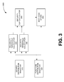
- FIG. 3 is a block diagram of system for iteratively selecting an optimized puncturing pattern distribution, according to some embodiments.
- System 300 includes: a degree distribution selector 310; a puncturing pattern distribution selector 320; a reliability threshold calculator 330; a security threshold calculator 340; a security gap calculator 350; and a best code store 360.
- System 300 begins operation by selecting two parameters describing the code to be generated.
- Degree distribution selector 310 selects the code's degree distribution, while puncturing pattern distribution selector 320 selects an initial puncturing pattern distribution.
- the degree distribution will remain constant while the puncturing pattern distribution is varied during the selection process.
- the selection by degree distribution selector 310 is not specific to the design of the security gap LPDC, so any criteria relevant to error correcting codes can be used.
- puncturing pattern distribution selector 320 is guided by previous iterations.
- the degree distribution and the initial puncturing pattern distribution are supplied to reliability threshold calculator 330, and to security threshold calculator 340. Each calculator block uses these inputs to perform its respective calculation of the current code's threshold.
- reliability threshold calculator 330 and security threshold calculator 340 each use density evolution to determine the asymptotic bit-error rate of the current code under consideration.
- density evolution tracks the evolution of the probability density function (PDF) of messages as they are passed between variable and check nodes during the decoding process.
- PDF probability density function
- the reliability threshold and the security threshold calculated by reliability threshold calculator 330 and security threshold calculator 340, respectively, are provided to security gap calculator 350, which calculates security gap 240, i . e ., the difference between these thresholds.
- the calculated security gap 240 for the current code under consideration is provided to best code store 360. Best code store 360 remembers the code with the lowest security gap 240 as the iterations progress. In some embodiments, best code store 360 remembers the code by storing the current puncturing pattern distribution. This is sufficient because the other parameter defining the code (the degree distribution) is fixed at the start.
- best code store 360 performs an explicit comparison of the current puncturing pattern distribution and the remembered puncturing pattern distribution, and replaces the remembered distribution with the current distribution if the current distribution has a lesser security gap value. In some embodiments, best code store 360 obtains the current puncturing pattern distribution from puncturing pattern distribution selector 320.
- puncturing pattern distribution selector 320 uses security gap 240 calculated by security threshold calculator 340 (representing the performance of the last code) and the history of previously chosen puncturing pattern distributions to guide selection of the next puncturing pattern distribution. In some embodiments, puncturing pattern distribution selector 320 uses differential evolution to choose the next puncturing pattern distribution.
- next iteration proceeds as described above, using the same initial degree distribution but a newly selected puncturing pattern distribution. If the next iteration produces a code with a lower security gap 240 than the first code, best code store 360 replaces the first code with the new code. Otherwise, the first code remains in best code store 360 unless and until a better code is found.
- the first term, P e 1 k is the contribution from the punctured variable nodes, while the second, P e 2 k , is the contribution from the unpunctured variable nodes.
- the fraction of punctured nodes is p
- security gaps 240 can be attained by using puncturing distributions that are specifically designed to improve security.
- SNR E be the maximum SNR for which P e , p k ⁇ P e E for any k .
- SNR B be the threshold of the punctured code. Then, for a given degree distribution ( ⁇ ( x ), ⁇ ( x )) and puncturing fraction p , the problem at hand is: argmin ⁇ i ⁇ ⁇ s ⁇ SNR B SNR E subject to
- Reduced security gap encoder 170 then implements one or more of codes designed by the algorithm.
- a code with good error-correcting performance is desired for receiver 110R.
- the code's error-correcting performance for eavesdropper 140 is desired to be very bad when eavesdropper 140 operates with a lower SNR.
- the puncturing algorithm described below makes this tradeoff in an efficient manner.
- An LDPC code can be described by a sparse bipartite graph which includes variable nodes and check nodes. This graph is used by iterative message passing algorithm (e.g., belief propagation) uses the graph to decode an LPDC.
- the received message is passed from variable nodes to check nodes, and from check nodes back to variable nodes.
- a variable node corresponding to a punctured bit (a "punctured variable node”) is recovered when it receives a non-zero message from at least one of its neighboring check nodes for the first time.
- a check node that provides the first non-zero message is called the survived check node.
- a punctured variable node is referred to as k-step recoverable ( k -SR) if it is recovered in the k-th iteration.
- the puncturing algorithm described below starts with an initial unpunctured code (mother code) and selects a particular puncturing pattern distribution for the initial code, by selecting particular nodes to be punctured variable nodes.
- the number K is chosen to be large enough that the error recovery probability at the eavesdropper's SNR is close to saturation. Typically, K is 2 or 3.
- FIG. 4 is a flow chart describing in more detail the puncturing algorithm to produce codes that provide security at finite block lengths, according to some embodiments.
- the process 400 begins at block 410, where a variable k is initialized to 1.
- a k -SR node is chosen, using a minimized k -SR criterion, to be a punctured variable node.
- the nodes in the code's graph are examined to find k-SR nodes and selected nodes are marked in some way as "punctured" nodes (e.g., type field, boolean field, or other mechanisms as appreciated by persons of ordinary skill in the art).
- Block 420 selects a k -SR node using a criterion which minimizes the overall number of selected k-SR nodes when the algorithm finishes.
- One minimization criterion is as follows.
- a k -SR variable node can be found if there exists a check node whose neighbors are either unpunctured or l- SR, where l ⁇ k .
- Such a check node is referred to herein as a recovery check node.
- a selection criterion which minimizes the numer of k -SR nodes is to choose (each time block 420 is performed) from all unpunctured variable nodes, a variable node with the most recovery check nodes to be a punctured variable node.
- the algorithm is run more than once to select more than one puncturing pattern distribution for the same initial (mother) code.
- Using more than one puncturing pattern distribution allows the secrecy rate and the security gap to be adapted at run time.
- the secrecy gap decreases with as the security rate decreases. This can be advantageous in dynamic environments where the relationship between the friendly receiver and the eavesdropper can vary over time. That is, sometimes an eavesdropper manages to come 'close' to the signal and consequently receives it with a better SNR, while other times it doesn't.
- all punctured nodes carry messages and the pattern itself is changed.
- the pattern is the same for all secrecy rates while messages are transmitted only over a subset of messages. Priority is given to those punctured nodes with high levels of recoverability.
- the recovery error P e r is used to explore the trade-off between the conflicting goals of a code with good error-correcting performance for receiver 110R but bad error-correcting performance for eavesdropper 140.
- AWGN additive white noise Gaussian
- FIG. 5 is a logical block diagram of a system 500 with a secure physical layer, according to some embodiments.
- System 500 includes transmitter 110T and receiver 110R each of which includes secure physical layer 510, link layer 520, and additional layer 530.
- System 500 takes advantage of the presence of reduced security gap encoder 170, which provides security, within physical layer 510.
- security provided at the physical layer replaces cryptographic algorithms at a higher layer (e . g ., wired equivalent privacy (WEP) at the media access control (MAC) layer, internet protocol security (IPSec) at the network layer, secure sockets layer (SSL) at the application layer, etc .)
- WEP wired equivalent privacy
- MAC media access control
- IPSec internet protocol security
- SSL secure sockets layer
- transmitter 110T and receiver 110R combine encryption at higher layers of the protocol stack with the security provided by reduced security gap encoder 170 at the physical layer.
- FIG. 6 is a block diagram illustrating selected components of one embodiment of secure physical layer 510.
- a transmit secure physical layer 510T includes a framer 610, reduced security gap encoder 170, and a modulator 620.
- Framer 610 operates on a message 605 from a higher protocol layer.
- Message 605 is a stream of bits.
- Framer 610 divides the bit stream into blocks, and outputs a block 615, which may include header and trailer information.
- Block 615 is encoded by reduced security gap encoder 170.
- Reduced security gap encoder 170 produces one or more encoded bits 625.
- Encoded bits 625 are modulated by modulator 620 to produce symbols, which are transmitted over main channel 120 to a receiver with secure physical layer 51 0R
- Receive secure physical layer 510R includes a demodulator 630, reduced security gap decoder 180, and a framer 640. Symbols received on main channel 120 are mapped to bits 645 by demodulator 630, and bits 645 are decoded by reduced security gap decoder 180. The group of decoded bits 655 is received by framer 640, which strips off header/trailer bits as necessary to reveal originally transmitted message 605. Message 605 may then be passed up to a higher protocol layer. Notably, message 605 is reconstructed without the transmission of any bits of the original message in the clear.
- one side of the communication channel has less processing or computing capabilities than the other.
- the properties of the communication channel may be asymmetrical (e . g ., 10 Mbit/sec in one direction and 1 Mbit/sec in the other).
- one side may use different modulation and/or framing techniques when transmitting than the other side does.
- one side may transmit using quadrature amplitude modulation with 16 different symbols (QAM16) while the other side may transmit using quadrature amplitude modulation with 64 different symbols (QAM64).
- FIG. 7 is a hardware block diagram of an embodiment of device 110.
- Device 110 contains a number of well known components, including a processor 710, a transceiver 720, memory 730, and non-volatile storage 740. These components are coupled via bus 750. Omitted from FIG. 7 are a number of conventional components, known to those skilled in the art, that are not necessary to explain the operation of device 110. Examples of non-volatile storage include, for example, a hard disk, flash RAM, flash ROM, EPROM, etc .
- Transceiver 720 may support one or more of a variety of different networks using various technologies, media, speeds, etc .
- wireless technologies includes: radio frequency identification (RFID) networks (e.g., ISO 14443, ISO 18000-6); wireless local area networks (e.g. IEEE 802.11, commonly known as WiFi); wireless wide area networks (e.g., IEEE 802.16, commonly known as WiMAX); wireless personal area networks (e.g., BluetoothTM, IEEE 802.15.4) and wireless telephone networks (e.g., CDMA, GSM, GPRS, EDGE).
- RFID radio frequency identification
- reduced security gap encoder 170 and reduced security gap decoder 180 are implemented in software, i . e ., instructions that are retrieved from a memory and then executed by processor 710.
- Processor 710 may take the form of, for example, a microprocessor, network processor, microcontroller, reconfigurable processor, extensible processor, graphics processor, etc .).
- Memory 730 contains encoder instructions 760 and/or decoder instructions 770, which programs or enables processor 710 to implement the functions of reduced security gap encoder 170 and/or reduced security gap decoder 180.
- reduced security gap encoder 170 and reduced security gap decoder 180 are stored on a computer-readable medium, which in the context of this disclosure refers to any structure which can contain, store, or embody instructions executable by a processor.
- the computer readable medium can be, for example but not limited to, based on electronic, magnetic, optical, electromagnetic, infrared, or semiconductor technology.
- Specific examples of a computer-readable medium using electronic technology would include (but are not limited to) the following: a random access memory (RAM); a read-only memory (ROM); and an erasable programmable read-only memory (EPROM or Flash memory).
- a specific example using magnetic technology includes (but is not limited to) a disk drive; and a portable computer diskette.
- Specific examples using optical technology include (but are not limited to) a compact disk read-only memory (CD-ROM) or a digital video disk read-only memory (DVD-ROM).
- reduced security gap encoder 170 and reduced security gap decoder 180 are implemented in digital hardware logic, as encoding logic and decoding logic.
- technologies used to implement encoding logic and decoding logic include, but are not limited to, a programmable logic device (PLD), a programmable gate array (PGA), field programmable gate array (FPGA), an application-specific integrated circuit (ASIC), a system on chip (SoC), and a system in package (SiP).
- PLD programmable logic device
- PGA programmable gate array
- FPGA field programmable gate array
- ASIC application-specific integrated circuit
- SoC system on chip
- SiP system in package
- Such digital logic implementations are not limited to pure digital but may also include analog sections or components.
- embodiments of device 110 which implement reduced security gap encoder 170 and reduced security gap decoder 180 with digital logic may also contain software to implement functions such as management, initialization of hardware, protocol stack layers, etc.
- reduced security gap encoder 170 and/or reduced security gap decoder 180 are implemented by a combination of software (i.e., instructions executed on a processor) and hardware logic.
- FIG. 7 depicts a communication device 110 that uses a puncture code to provide security, where the puncture code is designed and/or selected in accordance with the techniques described above in connection with FIGS. 1-5 .
- the design techniques described in connection with FIGs 1-5 are implemented on a computer which contains conventional components (such as those shown in FIG. 7 ), except that some embodiments of the computer used to design the code are not required to include a transceiver, since the computer that generates the code used in a communications device is not required to transmit or receive using the code.
- the methods of selecting puncturing pattern distributions described herein can be implemented in software, i . e ., as instructions that are retrieved from a memory and then executed by a processor.
- the memory then contains instructions which program or enable the processor to implement the methods of selecting puncturing pattern distributions as described herein.
- these methods of selecting puncturing pattern distributions can be implemented in digital hardware logic.
- these methods of selecting puncturing pattern distributions can be implemented in a combination of software and digital hardware logic.
Abstract
A computer-implemented method of selecting a puncturing pattern distribution for a low density parity check, LDPC, code for secure communication over a communication channel is disclosed. The LPDC is described by a graph containing a plurality of nodes, at least some of the nodes being kth step recoverable, k-SR, nodes and at least some of the nodes being punctured variable nodes. The method comprises selecting some of the k-SR nodes to be punctured variable nodes while minimizing the number of k-SR nodes for 1 <= k <= K and after the minimization, selecting other of the k-SR nodes to be punctured variable nodes while maximizing the number of k-SR nodes for k > K, wherein the puncturing pattern distribution is described by the arrangement of the punctured variable nodes. A transmitter and communication system that apply the codes is also disclosed.
Description
- The present disclosure relates to data communication, and more specifically, to a method and system for use in secure communication using error correcting codes.
- Error correcting codes are conventionally used to provide reliability over a noisy communication channel. An error correcting coding scheme transmits extra bits. These extra bits allow the receiver to recover errored bits by deducing the errored bits from the channel observations of the transmitted bits.
- Error correcting codes are conventionally designed to provide as much reliability as possible over a noisy channel. However, this high level of reliability leads to codes which are complex and thus require increased computational resources at the receiver.
- According to an aspect of the present invention, there is provided a computer-implemented method of selecting a puncturing pattern distribution for a low density parity check, LDPC, code for secure communication over a communication channel, the LPDC described by a graph containing a plurality of nodes, at least some of the nodes being kth step recoverable, k-SR, nodes and at least some of the nodes being punctured variable nodes, the method comprising:
- selecting some of the k-SR nodes to be punctured variable nodes while minimizing the number of k-SR nodes for 1 <= k <= K; and
- after the minimization, selecting other of the k-SR nodes to be punctured variable nodes while maximizing the number of k-SR nodes for k > K, wherein the puncturing pattern distribution is described by the arrangement of the punctured variable nodes.
- The minimizing and maximizing may steps comprise:
- initializing a variable k to 1;
- choosing one of the k-SR nodes to be a punctured variable node using a minimized k-SR criterion;
- when all of the k-SR nodes have been examined for minimization of a current value of k, incrementing k and comparing the incremented k to K;
- when the incremented k exceeds K, choosing one of the k-SR nodes to be a punctured variable node using a maximized k-SR criterion;
- when all of the k-SR nodes have been examined for minimization of a current value of k, incrementing k and determining whether all puncture nodes have been examined; and
- when all the puncture nodes have not been examined, repeating the choosing using the maximized k-SR criterion.
- The method may further comprise marking the chosen k-SR node as a punctured variable node.
- The choosing one of the k-SR nodes using the minimized k-SR criterion may comprise:
- examining a plurality of nodes in the graph to determine whether the node is a k-SR node.
- The method may further comprise:
- responsive to all of the k-SR nodes having examined for minimization of a current value of and to the incremented k not meeting or exceeding K, repeating the choosing using the minimized k-SR criterion.
- Choosing using the minimized k-SR criterion may comprise:
- choosing, from all unpunctured variable nodes in the graph, a variable node with more recovery check nodes than any other node.
- Choosing using the maximized k-SR criterion may use a grouping algorithm.
- The method may further comprise applying the selected code in a transmitter for puncturing a bit stream to be transmitted.
- The method may further comprising selecting a plurality of the codes, storing the plurality of codes in a communication system and selecting one of the plurality of codes for secure communication over a channel in dependence on one or more conditions associated with said channel or attributes of said channel.
- The method may further comprise applying the selected code in a receiver for reconstructing a received bit stream that has been punctured using the selected code.
- The method may be implemented in hardware, software, firmware or some combination thereof.
- According to another aspect of the present invention, there is provided a transmitter for a secure transmission system (510), the transmitter including a reduced security gap encoder (170) arranged to encode a received bit stream using a low density parity check code selected using the method described above for subsequent transmission.
- The reduced security gap encoder is preferably arranged to operate at a physical layer of a protocol stack.
- The transmitter may be arranged to cause disabling of encryption at one or more higher levels in the protocol stack.
- The transmitter may further comprise a repository storing or encoding a plurality of low density parity check codes selected using the above described method, wherein the transmitter is connectable to a communication channel for communicating the encoded bit stream, the transmitter being arranged to select, in dependence on one or more attributes of the communication channel or conditions associated with the communication channel, one of said codes from the repository for said encoding of the bit stream
- Disclosed herein are systems and methods of selecting and applying a puncturing pattern for a low density parity check (LDPC) code. The systems and methods are implemented in a computer. One such method comprises: selecting a puncturing pattern distribution for the LDPC code; calculating a security threshold and a reliability threshold for the LDPC, the LDPC having the selected puncturing pattern distribution and also described by a degree distribution; storing the selected puncturing pattern distribution responsive to a security gap for the LDPC being a lowest value encountered in any prior iterations; selecting another puncturing pattern distribution for the LDPC code; and repeating the calculating, the storing, and the selecting another puncturing pattern distribution steps.
- One such system is a computer configured to select a puncturing pattern for a low density parity check (LDPC) code. In this embodiment, the computer comprises: memory; and a processor. The processor is configured by instructions stored in the memory to: (a) select a puncturing pattern distribution for the LDPC code; (b) calculate a security threshold and a reliability threshold for the LDPC, the LDPC having the selected puncturing pattern distribution and also described by a degree distribution; (c) calculate a security gap between the security threshold and the reliability threshold; repeat b) and (c) after selecting another puncturing pattern distribution for the LDPC code; and output the selected puncturing pattern distribution having the lowest security gap.
- Embodiments of the present invention will now be described by way of example only with reference to the accompanying description. Many aspects of the disclosure can be better understood with reference to the following drawings. The components in the drawings are not necessarily to scale, emphasis instead being placed upon clearly illustrating the principles of the present disclosure.
-
FIG. 1 is a block diagram of a transmitter device and a receiver device utilizing non-systematic error correcting codes, according to some embodiments described herein. -
FIG. 2 is a graph illustrating the concept of a security gap. -
FIG. 3 is a block diagram of system for iteratively selecting an optimized puncturing pattern distribution, according to some embodiments. -
FIG. 4 is a flow chart of the puncturing algorithm to produce codes that provide security at finite block lengths, according to some embodiments. -
FIG. 5 is a logical block diagram of a system with a secure physical layer, according to some embodiments described herein. -
FIG. 6 is a block diagram illustrating selected components of a secure physical layer fromFIG. 4 , according to some embodiments described herein. -
FIG. 7 is a hardware block diagram of a device fromFIG.1 , according to some embodiments described herein. -
FIG. 1 is a block diagram of a transmitter device and a receiver device utilizing low-density parity-check (LDPC) codes to provide secure communication.System 100 includes two "friendly parties":device 110T, operating as a transmitter; and 110R, operating as a receiver. A person of ordinary skill in the art would understand that some embodiments of device 110 have both transmitter and receiver functionality.Transmitter 110T andreceiver 110R are in communication over amain channel 120, which is subject to anoise input 130. -
System 100 also includes another device 140 (an "eavesdropper") which is capable of listening to (eavesdropping on) transmissions onmain channel 120, over aneavesdropper channel 150. Eavesdropperchannel 150 is subject to anoise input 160. Eavesdropper 140 is passive with respect tomain channel 120, i.e., eavesdropper 140 does not jammain channel 120, insert bits onmain channel 120, etc. In some embodiments,main channel 120 and eavesdropperchannel 150 are wireless. In one of these embodiments,transmitter 110T takes the form of a radio frequency identification (RFID) tag. In still other embodiments,main channel 120 andeavesdropper channel 150 are wired (wire line) channels. - The embodiments described herein utilize specially designed LDPC codes to insure communication between friendly parties that is both reliable and secure. Use of such LDPC codes takes advantage of environments in which the signal quality on main channel 120 (the channel between a "friendly" transmitter and a "friendly" receiver) is better than the signal quality on
eavesdropper channel 150. This difference in signal quality may be guaranteed, for example, when the eavesdropper is more than a certain distance away from the friendly transmitter. -
Transmitter 110T includes a reducedsecurity gap encoder 170, which applies a reduced security gap LDPC code (described below) during message transmission.Receiver 110R includes a complementary reducedsecurity gap decoder 180, so that reducedsecurity gap encoder 170 cooperates with reducedsecurity gap decoder 180 to provide secure communication overmain channel 120. Reducedsecurity gap encoder 170 uses puncturing to hide data fromeavesdropper 140, such that all message bits are punctured in reducedsecurity gap encoder 170 rather than being transmitted. Reducedsecurity gap decoder 180 must then deduce the message bits from channel observations of those bits that were transmitted. As long as the signal quality oneavesdropper channel 150 is low, the channel observations are expected to be very noisy. Therefore, reconstruction of the punctured message bits by a decoder withineavesdropper 140 is expected to be hard. The measure of secrecy is the bit-error-rate (BER) over message bits. - Consider the scenario in which "friendly"
transmitter 110T wants to transmit an s-bit message Ms to "friendly"receiver 110R.Transmitter 110T uses an error correcting code to encode Ms to an n-bit codeword Xn and transmits Xn over an additive white Gaussian noise (AWGN) channel toreceiver 110R.Eavesdropper 140 listens to the transmission over a noisier, independent AWGN channel and tries to reconstruct the message Ms .Eavesdropper 140 is assumed to be passive, and thus not allowed to transmit data, so as to jam or interfere in the communication betweentransmitter 110T andreceiver 110R. - Let an average bit-error-rate (BER) over the estimate

receiver 110R be

eavesdropper 140 be


- a)

- b)

- Let SNRB,min be the lowest signal-to-noise ration (SNR) for which condition a) holds, and let SNRE,max and be the highest SNR for which condition b) holds. It is assumed that
receiver 110R operates at SNRB,min and that the SNR ofeavesdropper 140 is strictly lower than SNR B, min. - The quantity SNR B,min /SNR E,max is referred to herein as the "security gap". The security gap is alternatively expressed in dB. The size of the security gap in dB describes the minimum required difference between the SNR of
receiver 110R and the SNR ofeavesdropper 140 to ensure secure communication. Conventional error correcting codes require large (more than approximately 20 dB) security gaps when
-
FIG. 2 is a graph illustrating the concept of the security gap.Curve 210 shows BER versus SNR performance of an example error correction code. SNRB,min is thereliability threshold 220, i.e., the threshold which ensures reliability betweentransmitter 110T andreceiver 110R. SNR E,max is thesecurity threshold 230, i.e., the threshold at which eavesdropper 140 has an appropriately high error rate (e.g., 0.5) to ensure security. The security gap discussed above can be seen inFIG. 2 asarea 240, corresponding to the area of code performance which is neither secure enough nor sufficiently reliable. The error correcting coding scheme described herein is specifically designed to generate codes having a performance curve with a small security gap, thus ensuring that a small difference in signal quality results in a transition from the reliable region to the secure region. - The coding scheme disclosed herein uses a particular class of error correcting code known as low-density parity-check (LDPC) codes. The decoder used by both
receiver 110R andeavesdropper 140 is assumed to be a belief propagation decoder, which is asymptotically equal to the powerful bitwise maximum a-posteriori (MAP) decoder. Transmitting messages over punctured bits can significantly reduce security gaps and can thus be efficiently used for increased security of data. Security gaps as low as few dB are sufficient to forceeavesdropper 140 to operate at BER above 0.49. As will be described in more detail in connection withFIG. 5 , this coding scheme, which provides security at the physical layer, can be used in conjunction with existing cryptographic schemes which operate on higher layers of the protocol stack. - An LDPC code can be specified by means of a bipartite graph, composed of variable nodes representing codeword bits and check nodes representing the constraints imposed on the codeword bits. One parameter that describes the bipartite graph of an LDPC code is the degree distribution, which is given in the form of two polynomials


- Another parameter that describes an LPDC is the reliability threshold (220 in
FIG. 2 ). A code's reliability threshold is defined as the lowest SNR at which the belief propagation decoder can yield arbitrarily low BERs. - A punctured LDPC code is a code where some of the variable nodes are not transmitted. A puncturing pattern distribution


- The coding scheme disclosed herein transmits messages over punctured bits. The puncturing pattern distribution is selected so that no subset of punctured bits forms a stopping set; otherwise, some punctured (message) bits would not be recoverable in the decoder.
- Let the dimension of an LDPC code be d, let the number of message bits be s, and let the number of transmitted codeword bits be n. The code rate is defined as

- while the secrecy rate is defined as

- It is possible, in some scenarios, that the number of punctured (message) bits is smaller than d. In such cases, punctured message bits are coupled with some randomly chosen dummy bits to occupy all independent bit locations in a codeword. Usually in such cases Rs < Rd . If a code is left unpunctured, and assuming that all independent bit locations carry messages, then Rs = Rd .
- As discussed above, specially designed punctured LDPC codes can exploit the security gap between the friendly and eavesdropper channels, to provide acceptable security without the unnecessary complexity. As noted above, an LDPC code can be described in terms of a puncturing pattern distribution and a degree distribution. A system and method for designing a security gap LPDC will now be described. Reduced
security gap encoder 170 then implements one or more of these codes. The method, and the system which implements the method, optimizes the puncturing pattern distribution for LPDCs having a relatively large block length (on the order of 50,000 bits or more). Although such codes are finite in length, asymptotic results are likely to hold for these very long codes, as with codes of infinite length. - The method, and system which implements the method, involves iteratively selecting an optimized puncturing pattern distribution for a code with a given degree distribution. While iterating, the reliability and security thresholds of the current code under consideration are calculated. The method keeps the code with the lowest security gap encountered so far.
-
FIG. 3 is a block diagram of system for iteratively selecting an optimized puncturing pattern distribution, according to some embodiments.System 300 includes: adegree distribution selector 310; a puncturingpattern distribution selector 320; areliability threshold calculator 330; asecurity threshold calculator 340; asecurity gap calculator 350; and abest code store 360.System 300 begins operation by selecting two parameters describing the code to be generated.Degree distribution selector 310 selects the code's degree distribution, while puncturingpattern distribution selector 320 selects an initial puncturing pattern distribution. The degree distribution will remain constant while the puncturing pattern distribution is varied during the selection process. The selection bydegree distribution selector 310 is not specific to the design of the security gap LPDC, so any criteria relevant to error correcting codes can be used. As will be discussed shortly, puncturingpattern distribution selector 320 is guided by previous iterations. - The degree distribution and the initial puncturing pattern distribution are supplied to
reliability threshold calculator 330, and tosecurity threshold calculator 340. Each calculator block uses these inputs to perform its respective calculation of the current code's threshold. In some embodiments,reliability threshold calculator 330 andsecurity threshold calculator 340 each use density evolution to determine the asymptotic bit-error rate of the current code under consideration. As should be appreciated by a person of ordinary skill in the art, density evolution tracks the evolution of the probability density function (PDF) of messages as they are passed between variable and check nodes during the decoding process. A simplified form of density evolution assumes that messages have Gaussian probability distribution functions, so that density evolution can be reduced to tracking only one parameter: the mean
- The reliability threshold and the security threshold calculated by
reliability threshold calculator 330 andsecurity threshold calculator 340, respectively, are provided tosecurity gap calculator 350, which calculatessecurity gap 240, i.e., the difference between these thresholds. Thecalculated security gap 240 for the current code under consideration is provided tobest code store 360.Best code store 360 remembers the code with thelowest security gap 240 as the iterations progress. In some embodiments,best code store 360 remembers the code by storing the current puncturing pattern distribution. This is sufficient because the other parameter defining the code (the degree distribution) is fixed at the start. - In some embodiments,
best code store 360 performs an explicit comparison of the current puncturing pattern distribution and the remembered puncturing pattern distribution, and replaces the remembered distribution with the current distribution if the current distribution has a lesser security gap value. In some embodiments,best code store 360 obtains the current puncturing pattern distribution from puncturingpattern distribution selector 320. - Having generated a first code based on the initial puncturing pattern distribution pattern,
system 300 starts another iteration to generate another code having a different puncturing pattern distribution. In this next iteration, puncturingpattern distribution selector 320 usessecurity gap 240 calculated by security threshold calculator 340 (representing the performance of the last code) and the history of previously chosen puncturing pattern distributions to guide selection of the next puncturing pattern distribution. In some embodiments, puncturingpattern distribution selector 320 uses differential evolution to choose the next puncturing pattern distribution. - This next iteration proceeds as described above, using the same initial degree distribution but a newly selected puncturing pattern distribution. If the next iteration produces a code with a
lower security gap 240 than the first code,best code store 360 replaces the first code with the new code. Otherwise, the first code remains inbest code store 360 unless and until a better code is found. - Having described a system and method for selecting an asymptotic LPDC code with a reduced gap, a theoretical framework will now be described. The asymptotic analysis used below demonstrates that that transmitting messages are transmitted over punctured bits significantly reduces the security gap. Message in the belief propagation decoder are assumed to be Gaussian, so that the mean value of check-to-variable node messages in the k-th iteration is


where

0 = 2/σ2 and σ2 is the noise variance. - Using


- The first term,


- As noted above,
security gaps 240 can be attained by using puncturing distributions that are specifically designed to improve security. With the theoretical framework described above, optimization of puncturing distributions can be described as follows. Let SNRE be the maximum SNR for which

subject to - 0 ≤ π i ≤ 1 forall2 ≤ i ≤ dv ,
-

- SNRB < ∞ ,
- SNRE > -∞ .
- The sections above describe the design of reduced security gap LPDC codes with relatively block lengths. The performance of such codes was also analyzed. A system and method of designing reduced security gap LPDC codes having much smaller block lengths will now be described. In particular, a puncturing algorithm for security at finite block lengths will be disclosed. Reduced
security gap encoder 170 then implements one or more of codes designed by the algorithm. As noted above, in an environment involving twofriendly parties eavesdropper 140, a code with good error-correcting performance is desired forreceiver 110R. Yet at the same time, the code's error-correcting performance foreavesdropper 140 is desired to be very bad wheneavesdropper 140 operates with a lower SNR. The puncturing algorithm described below makes this tradeoff in an efficient manner. - Before describing the puncturing algorithm, a brief review of LPDC decoding will be presented. However, a person of ordinary skill in the art is expected to be familiar with this terminology. An LDPC code can be described by a sparse bipartite graph which includes variable nodes and check nodes. This graph is used by iterative message passing algorithm (e.g., belief propagation) uses the graph to decode an LPDC. At each round, the received message is passed from variable nodes to check nodes, and from check nodes back to variable nodes. A variable node corresponding to a punctured bit (a "punctured variable node") is recovered when it receives a non-zero message from at least one of its neighboring check nodes for the first time. A check node that provides the first non-zero message is called the survived check node. A punctured variable node is referred to as k-step recoverable (k-SR) if it is recovered in the k-th iteration.
- The puncturing algorithm described below starts with an initial unpunctured code (mother code) and selects a particular puncturing pattern distribution for the initial code, by selecting particular nodes to be punctured variable nodes. The algorithm selects a desirable puncturing pattern distribution by first minimizing the number of k-SR nodes, where 1 <= k <= K. This first minimization results in a code which "confuses" the eavesdropper with a low SNR. Then, for k > K the number of k-SR nodes is maximized, which results in a code which "helps" the friendly listener with a high SNR. The number K is chosen to be large enough that the error recovery probability at the eavesdropper's SNR is close to saturation. Typically, K is 2 or 3.
-
FIG. 4 is a flow chart describing in more detail the puncturing algorithm to produce codes that provide security at finite block lengths, according to some embodiments. Theprocess 400 begins atblock 410, where a variable k is initialized to 1. Atblock 420, a k-SR node is chosen, using a minimized k-SR criterion, to be a punctured variable node. In this regard, the nodes in the code's graph are examined to find k-SR nodes and selected nodes are marked in some way as "punctured" nodes (e.g., type field, boolean field, or other mechanisms as appreciated by persons of ordinary skill in the art). -
Block 420 selects a k-SR node using a criterion which minimizes the overall number of selected k-SR nodes when the algorithm finishes. One minimization criterion is as follows. A k-SR variable node can be found if there exists a check node whose neighbors are either unpunctured or l-SR, where l < k. Such a check node is referred to herein as a recovery check node. A selection criterion which minimizes the numer of k-SR nodes is to choose (each time block 420 is performed) from all unpunctured variable nodes, a variable node with the most recovery check nodes to be a punctured variable node. -
Block 430 determines whether any more k-SR nodes exist in the code graph. If Yes, processing continues atblock 420 with other k-SR nodes. When all k-SR nodes have been examined for the current value of k, processing moves to block 440, where k is incremented. Next, block 450 compares k to K. If k <= K, the process repeats starting atblock 420, where a k-SR nodes is selected again using a minimized k-SR criteria, but with a new value of k. Ifblock 450 determines instead that k > K, the loop ends. At this point, the number of k-SR nodes has been minimized for 1 <= k <= K. - With k being K+1 after exiting the loop, processing continues at
block 460 where k-SR nodes are maximized. Persons of ordinary skill in the art will appreciate various methods of maximizing the overall number of selected k-SR nodes, such as the grouping algorithm.Block 470 determines whether any more k-SR nodes exist in the code graph. If Yes, processing continues atblock 460 with over k-SR nodes. When all k-SR nodes have been examined for the current value of k, processing moves to block 480, where k is incremented.Block 490 determines whether any more punctured nodes can be found. If yes, processing repeats starting atblock 460, where k-SR nodes are maximized again, but with a new value of k. If no more punctured nodes can be found, theprocess 400 ends. At this point, the number of k-SR nodes has been maximized for k > K and minimized for 1 <= k <= K. - The arrangement of punctured variable nodes in the tripartite graph describes the puncturing pattern distribution of the LPDC. Punctured variable nodes can be described in terms of how many steps it takes the decoder to recover the encoded information, where a k-step recoverable (k-SR) node is recovered in the k-th iteration. Selecting punctured variable nodes in the graph to minimize the total number of some k-SR nodes (those for 1 <= k <= K) and to maximize the total number of other k-SR nodes (those for k > K) produces a code which confuses the eavesdropper while helping the friendly receiver.
- In some embodiments, the algorithm is run more than once to select more than one puncturing pattern distribution for the same initial (mother) code. Using more than one puncturing pattern distribution allows the secrecy rate and the security gap to be adapted at run time. Generally, the secrecy gap decreases with as the security rate decreases. This can be advantageous in dynamic environments where the relationship between the friendly receiver and the eavesdropper can vary over time. That is, sometimes an eavesdropper manages to come 'close' to the signal and consequently receives it with a better SNR, while other times it doesn't.
- In some embodiments, all punctured nodes carry messages and the pattern itself is changed. In other embodiments, the pattern is the same for all secrecy rates while messages are transmitted only over a subset of messages. Priority is given to those punctured nodes with high levels of recoverability.
- Having described a system and method which implements a puncturing algorithm to produce codes that provide security at finite block lengths, a theoretical framework for understanding the performance of such codes will now be described. The recovery error

receiver 110R but bad error-correcting performance foreavesdropper 140. The formula for

where
- These equations can be used to explore the behavior of recovery error probability

eavesdropper 140 than on the performance ofreceiver 110R. In contrast, when recovery error probability ateavesdropper 140 is close to saturation, increasing the number of nodes does seem reasonable, since the performance ofeavesdropper 140 is already at levels where it can not deteriorate much further while the performance offriendly receiver 110R suffers. -
FIG. 5 is a logical block diagram of a system 500 with a secure physical layer, according to some embodiments. System 500 includestransmitter 110T andreceiver 110R each of which includes securephysical layer 510,link layer 520, andadditional layer 530. System 500 takes advantage of the presence of reducedsecurity gap encoder 170, which provides security, withinphysical layer 510. In this embodiment, security provided at the physical layer replaces cryptographic algorithms at a higher layer (e.g., wired equivalent privacy (WEP) at the media access control (MAC) layer, internet protocol security (IPSec) at the network layer, secure sockets layer (SSL) at the application layer, etc.) - The coding techniques disclosed herein do provide security at the physical layer, but these techniques can also be used in combination with any protocol layer above the physical layer. Thus, some embodiments of
transmitter 110T andreceiver 110R (not shown) combine encryption at higher layers of the protocol stack with the security provided by reducedsecurity gap encoder 170 at the physical layer. -
FIG. 6 is a block diagram illustrating selected components of one embodiment of securephysical layer 510. A transmit securephysical layer 510T includes aframer 610, reducedsecurity gap encoder 170, and amodulator 620.Framer 610 operates on amessage 605 from a higher protocol layer.Message 605 is a stream of bits.Framer 610 divides the bit stream into blocks, and outputs ablock 615, which may include header and trailer information.Block 615 is encoded by reducedsecurity gap encoder 170. Reducedsecurity gap encoder 170 produces one or more encodedbits 625. Encodedbits 625 are modulated bymodulator 620 to produce symbols, which are transmitted overmain channel 120 to a receiver with secure physical layer 51 0R - Receive secure
physical layer 510R includes ademodulator 630, reducedsecurity gap decoder 180, and aframer 640. Symbols received onmain channel 120 are mapped tobits 645 bydemodulator 630, andbits 645 are decoded by reducedsecurity gap decoder 180. The group of decodedbits 655 is received byframer 640, which strips off header/trailer bits as necessary to reveal originally transmittedmessage 605.Message 605 may then be passed up to a higher protocol layer. Notably,message 605 is reconstructed without the transmission of any bits of the original message in the clear. - In some embodiments, one side of the communication channel has less processing or computing capabilities than the other. In some embodiments, the properties of the communication channel may be asymmetrical (e.g., 10 Mbit/sec in one direction and 1 Mbit/sec in the other). In such embodiments, one side may use different modulation and/or framing techniques when transmitting than the other side does. As a non-limiting example, one side may transmit using quadrature amplitude modulation with 16 different symbols (QAM16) while the other side may transmit using quadrature amplitude modulation with 64 different symbols (QAM64).
-
FIG. 7 is a hardware block diagram of an embodiment of device 110. Device 110 contains a number of well known components, including aprocessor 710, atransceiver 720,memory 730, andnon-volatile storage 740. These components are coupled via bus 750. Omitted fromFIG. 7 are a number of conventional components, known to those skilled in the art, that are not necessary to explain the operation of device 110. Examples of non-volatile storage include, for example, a hard disk, flash RAM, flash ROM, EPROM, etc. -
Transceiver 720 may support one or more of a variety of different networks using various technologies, media, speeds, etc. A non-limiting list of examples of wireless technologies includes: radio frequency identification (RFID) networks (e.g., ISO 14443, ISO 18000-6); wireless local area networks (e.g. IEEE 802.11, commonly known as WiFi); wireless wide area networks (e.g., IEEE 802.16, commonly known as WiMAX); wireless personal area networks (e.g., Bluetooth™, IEEE 802.15.4) and wireless telephone networks (e.g., CDMA, GSM, GPRS, EDGE). - In the embodiment of
FIG. 7 , reducedsecurity gap encoder 170 and reducedsecurity gap decoder 180 are implemented in software, i.e., instructions that are retrieved from a memory and then executed byprocessor 710.Processor 710 may take the form of, for example, a microprocessor, network processor, microcontroller, reconfigurable processor, extensible processor, graphics processor, etc.).Memory 730 containsencoder instructions 760 and/ordecoder instructions 770, which programs or enablesprocessor 710 to implement the functions of reducedsecurity gap encoder 170 and/or reducedsecurity gap decoder 180. - Some embodiments of reduced
security gap encoder 170 and reducedsecurity gap decoder 180 are stored on a computer-readable medium, which in the context of this disclosure refers to any structure which can contain, store, or embody instructions executable by a processor. The computer readable medium can be, for example but not limited to, based on electronic, magnetic, optical, electromagnetic, infrared, or semiconductor technology. Specific examples of a computer-readable medium using electronic technology would include (but are not limited to) the following: a random access memory (RAM); a read-only memory (ROM); and an erasable programmable read-only memory (EPROM or Flash memory). A specific example using magnetic technology includes (but is not limited to) a disk drive; and a portable computer diskette. Specific examples using optical technology include (but are not limited to) a compact disk read-only memory (CD-ROM) or a digital video disk read-only memory (DVD-ROM). - In some embodiments (not shown), reduced
security gap encoder 170 and reducedsecurity gap decoder 180 are implemented in digital hardware logic, as encoding logic and decoding logic. Technologies used to implement encoding logic and decoding logic include, but are not limited to, a programmable logic device (PLD), a programmable gate array (PGA), field programmable gate array (FPGA), an application-specific integrated circuit (ASIC), a system on chip (SoC), and a system in package (SiP). Such digital logic implementations are not limited to pure digital but may also include analog sections or components. - Furthermore, embodiments of device 110 which implement reduced
security gap encoder 170 and reducedsecurity gap decoder 180 with digital logic may also contain software to implement functions such as management, initialization of hardware, protocol stack layers, etc. In yet another embodiment of device 110 (not illustrated), reducedsecurity gap encoder 170 and/or reducedsecurity gap decoder 180 are implemented by a combination of software (i.e., instructions executed on a processor) and hardware logic. -
FIG. 7 depicts a communication device 110 that uses a puncture code to provide security, where the puncture code is designed and/or selected in accordance with the techniques described above in connection withFIGS. 1-5 . The design techniques described in connection withFIGs 1-5 are implemented on a computer which contains conventional components (such as those shown inFIG. 7 ), except that some embodiments of the computer used to design the code are not required to include a transceiver, since the computer that generates the code used in a communications device is not required to transmit or receive using the code. - In this regard, the methods of selecting puncturing pattern distributions described herein can be implemented in software, i.e., as instructions that are retrieved from a memory and then executed by a processor. The memory then contains instructions which program or enable the processor to implement the methods of selecting puncturing pattern distributions as described herein. Alternatively, these methods of selecting puncturing pattern distributions can be implemented in digital hardware logic. As yet another alternative, these methods of selecting puncturing pattern distributions can be implemented in a combination of software and digital hardware logic.
- Any process descriptions or blocks in flowcharts would be understood as representing modules, segments, or portions of code which include one or more executable instructions for implementing specific functions or steps in the process. As would be understood by those of ordinary skill in the art of the software development, alternate implementations are also included within the scope of the present invention as defined by the claims. In these alternate implementations, functions may be executed out of order from that shown or discussed, including substantially concurrently or in reverse order, depending on the functionality involved.
- The foregoing description has been presented for purposes of illustration and description. It is not intended to be exhaustive or to limit the disclosure to the precise forms disclosed. Obvious modifications or variations are possible in light of the above teachings. The implementations discussed, however, were chosen and described to illustrate the principles of the disclosure and its practical application to thereby enable one of ordinary skill in the art to utilize the disclosure in various implementations and with various modifications as are suited to the particular use contemplated. All such modifications and variation are within the scope of the disclosure as determined by the appended claims when interpreted in accordance with the breadth to which they are fairly and legally entitled.
- The disclosures in
U.S. Provisional Application No. 61/171,937, filed April 23, 2009
Claims (15)
- A computer-implemented method of selecting a puncturing pattern distribution for a low density parity check, LDPC, code for secure communication over a communication channel, the LPDC described by a graph containing a plurality of nodes, at least some of the nodes being kth step recoverable, k-SR, nodes and at least some of the nodes being punctured variable nodes, the method comprising:selecting some of the k-SR nodes to be punctured variable nodes while minimizing the number of k-SR nodes for 1 <= k <= K; andafter the minimization, selecting other of the k-SR nodes to be punctured variable nodes while maximizing the number of k-SR nodes for k > K, wherein the puncturing pattern distribution is described by the arrangement of the punctured variable nodes.
- The method of claim 1, wherein the minimizing and maximizing steps comprise:initializing a variable k to 1;choosing one of the k-SR nodes to be a punctured variable node using a minimized k-SR criterion;when all of the k-SR nodes have been examined for minimization of a current value of k, incrementing k and comparing the incremented k to K;when the incremented k exceeds K, choosing one of the k-SR nodes to be a punctured variable node using a maximized k-SR criterion;when all of the k-SR nodes have been examined for minimization of a current value of k, incrementing k and determining whether all puncture nodes have been examined; andwhen all the puncture nodes have not been examined, repeating the choosing using the maximized k-SR criterion.
- The method of claim 1, further comprising marking the chosen k-SR node as a punctured variable node.
- The method of claim 2, wherein the choosing one of the k-SR nodes using the minimized k-SR criterion comprises:examining a plurality of nodes in the graph to determine whether the node is a k-SR node.
- The method of claim 2, 3 or 4, further comprising:responsive to all of the k-SR nodes having examined for minimization of a current value of and to the incremented k not meeting or exceeding K, repeating the choosing using the minimized k-SR criterion.
- The method of any of claims 2 to 5, wherein the choosing using the minimized k-SR criterion comprises:choosing, from all unpunctured variable nodes in the graph, a variable node with more recovery check nodes than any other node.
- The method of any of claims 2 to 6, wherein the choosing using the maximized k-SR criterion includes using a grouping algorithm.
- The method of any preceding claim, further comprising applying the selected code in a transmitter for puncturing a bit stream to be transmitted.
- The method of any preceding claim, further comprising selecting a plurality of codes, storing the plurality of codes in a communication system and selecting one of the plurality of codes for secure communication over a channel in dependence on one or more conditions associated with said channel or attributes of said channel.
- The method of any of claims 1 to 8, further comprising applying the selected code in a receiver for reconstructing a received bit stream that has been punctured using the selected code.
- A computer program comprising computer program code means for performing all of the steps of any of claims 1 to 10 when said program is run on a computer.
- A computer program as claimed in claim 11 embodied on a computer readable medium.
- A transmitter for a secure transmission system (510), the transmitter including a reduced security gap encoder (170) arranged to encode a received bit stream using a low density parity check code selected using the method of any of claims 1 to 7 for subsequent transmission.
- A transmitter as claimed in claim 13, wherein the reduced security gap encoder is arranged to operate at a physical layer of a protocol stack.
- A transmitter as claimed in claim 13 or 14, further comprising a repository storing or encoding a plurality of low density parity check codes selected using the method of any of claims 1 to 7, wherein the transmitter is connectable to a communication channel for communicating the encoded bit stream, the transmitter being arranged to select, in dependence on one or more attributes of the communication channel or conditions associated with the communication channel, one of said codes from the repository for said encoding of the bit stream.
Applications Claiming Priority (1)
| Application Number | Priority Date | Filing Date | Title |
|---|---|---|---|
| US17193709P | 2009-04-23 | 2009-04-23 |
Publications (1)
| Publication Number | Publication Date |
|---|---|
| EP2244387A1 true EP2244387A1 (en) | 2010-10-27 |
Family
ID=42290129
Family Applications (1)
| Application Number | Title | Priority Date | Filing Date |
|---|---|---|---|
| EP10160921A Withdrawn EP2244387A1 (en) | 2009-04-23 | 2010-04-23 | Method and transmitter for use in secure communication using error correction codes |
Country Status (3)
| Country | Link |
|---|---|
| US (1) | US8484545B2 (en) |
| EP (1) | EP2244387A1 (en) |
| KR (1) | KR20100117051A (en) |
Cited By (1)
| Publication number | Priority date | Publication date | Assignee | Title |
|---|---|---|---|---|
| US10243730B2 (en) | 2013-10-17 | 2019-03-26 | Samsung Electronics Co., Ltd. | Apparatus and method for encrypting data in near field communication system |
Families Citing this family (11)
| Publication number | Priority date | Publication date | Assignee | Title |
|---|---|---|---|---|
| US8667380B2 (en) * | 2008-10-09 | 2014-03-04 | Georgia Tech Research Corporation | Secure communication using non-systematic error control codes |
| US8821427B1 (en) * | 2011-02-03 | 2014-09-02 | Weber Orthopedic Inc. | Rear entry ankle brace with medial and lateral access |
| EP2957037A1 (en) | 2013-02-13 | 2015-12-23 | Qualcomm Incorporated | Ldpc design using quasi-cyclic constructions and puncturing for high rate, high parallelism, and low error floor |
| US9479285B2 (en) * | 2013-10-14 | 2016-10-25 | Nec Corporation | Non-binary LDPC coded mode-multiplexed four-dimensional signaling based on orthogonal frequency division multiplexing |
| US9264074B2 (en) * | 2014-02-11 | 2016-02-16 | Entropic Communications, Llc | LDPC code matrices |
| US10784901B2 (en) | 2015-11-12 | 2020-09-22 | Qualcomm Incorporated | Puncturing for structured low density parity check (LDPC) codes |
| US11043966B2 (en) | 2016-05-11 | 2021-06-22 | Qualcomm Incorporated | Methods and apparatus for efficiently generating multiple lifted low-density parity-check (LDPC) codes |
| US10454499B2 (en) * | 2016-05-12 | 2019-10-22 | Qualcomm Incorporated | Enhanced puncturing and low-density parity-check (LDPC) code structure |
| US10291354B2 (en) | 2016-06-14 | 2019-05-14 | Qualcomm Incorporated | High performance, flexible, and compact low-density parity-check (LDPC) code |
| US10897271B2 (en) * | 2018-10-04 | 2021-01-19 | Western Digital Technologies, Inc. | Multi-dimensional quasi-cyclic (QC) low-density parity-check (LDPC) code constructions |
| CN113556134B (en) * | 2021-06-28 | 2022-09-16 | 杭州电子科技大学 | Polar code puncturing encoder and encoding method suitable for simplifying serial offset decoding |
Family Cites Families (6)
| Publication number | Priority date | Publication date | Assignee | Title |
|---|---|---|---|---|
| GB2371952A (en) * | 2001-01-31 | 2002-08-07 | Inmarsat Ltd | Frame synchronisation in a communication system |
| US7269138B2 (en) * | 2003-06-04 | 2007-09-11 | Motorola, Inc. | Distributed MAC protocol facilitating collaborative ranging in communications networks |
| KR100640399B1 (en) * | 2004-10-27 | 2006-10-30 | 삼성전자주식회사 | Puncturing method for ldpc channel code |
| KR100703483B1 (en) * | 2005-03-04 | 2007-04-03 | 삼성전자주식회사 | Method for puncturing ldpc code |
| KR101351140B1 (en) * | 2005-11-22 | 2014-01-15 | 조지아 테크 리서치 코오포레이션 | Apparatus and method for transmitting/receiving signal in a communication system |
| US8132072B2 (en) * | 2006-01-06 | 2012-03-06 | Qualcomm Incorporated | System and method for providing H-ARQ rate compatible codes for high throughput applications |
-
2010
- 2010-04-23 US US12/765,966 patent/US8484545B2/en not_active Expired - Fee Related
- 2010-04-23 KR KR1020100038150A patent/KR20100117051A/en not_active Application Discontinuation
- 2010-04-23 EP EP10160921A patent/EP2244387A1/en not_active Withdrawn
Non-Patent Citations (3)
| Title |
|---|
| JEONGSEOK HA, JAEHONG KIM, ANDSTEVEN W. MCLAUGHLIN,: "Rate-Compatible Puncturing of Low-DensityParity-Check Codes", IEEE TRANSACTIONS ON INFORMATION THEORY, VOL. 50, NO. 11,, November 2004 (2004-11-01), XP002590771 * |
| JEONGSEOKHA, JAEHONG KIM, DEMIJAN KLINC, ANDSTEVEN W. MCLAUGHLIN,: "Rate-Compatible Punctured Low-Density Parity-CheckCodes With Short Block Lengths", IEEE TRANSACTIONS ON INFORMATION THEORY, VOL. 52, NO. 2,, 2006, XP002590809, Retrieved from the Internet <URL:http://ieeexplore.ieee.org/stamp/stamp.jsp?tp=&arnumber=1580808&userType=&tag=1> [retrieved on 20100707] * |
| SUNGHOON CHOI, KWANGSEOK NOH, JEONG HWAN SHINY AND JUN HEO: "Rate-Compatible Punctured LDPC Codes based on Recovery Tree", INTERNATIONAL SYMPOSIUM ON INFORMATION THEORY AND ITS APPLICATIONS, ISITA2008, December 2008 (2008-12-01), XP002590772, Retrieved from the Internet <URL:http://ieeexplore.ieee.org/stamp/stamp.jsp?arnumber=04895650&tag=1> [retrieved on 20100707] * |
Cited By (1)
| Publication number | Priority date | Publication date | Assignee | Title |
|---|---|---|---|---|
| US10243730B2 (en) | 2013-10-17 | 2019-03-26 | Samsung Electronics Co., Ltd. | Apparatus and method for encrypting data in near field communication system |
Also Published As
| Publication number | Publication date |
|---|---|
| US8484545B2 (en) | 2013-07-09 |
| US20100275093A1 (en) | 2010-10-28 |
| KR20100117051A (en) | 2010-11-02 |
Similar Documents
| Publication | Publication Date | Title |
|---|---|---|
| US8484545B2 (en) | Secure communication using error correction codes | |
| US10886950B2 (en) | Method and apparatus for generating a code word | |
| US11165537B2 (en) | Method for encoding information bit sequence in communication network | |
| EP3510700B1 (en) | Method and apparatus for encoding data using a polar code | |
| JP6817452B2 (en) | Rate matching method, encoding device, and communication device | |
| US8369448B2 (en) | Bit mapping scheme for an LDPC coded 32APSK system | |
| US9319070B2 (en) | Method and device for decoding polar codes | |
| KR101004584B1 (en) | H-arq rate compatible low-density parity-check ldpc codes for high throughput applications | |
| RU2716044C1 (en) | Methods and systems for encoding and decoding ldpc codes | |
| US20040268205A1 (en) | Low-density parity-check codes for multiple code rates | |
| US11316538B2 (en) | Polar code encoding method and apparatus | |
| CN107395319B (en) | Code rate compatible polarization code coding method and system based on punching | |
| US20110246854A1 (en) | Secure Communication Using Non-Systematic Error Control Codes | |
| US20130272456A1 (en) | Decoding apparatus and decoding method for decoding data encoded by ldpc | |
| KR20090063922A (en) | Apparatus and method for receiving signal in a communication system | |
| CN101150377A (en) | Bit mapping scheme of 32APSK system for low-density checksum coding | |
| US7458003B2 (en) | Low-complexity, capacity-achieving code for communication systems | |
| US20240128988A1 (en) | Method and device for polar code encoding and decoding | |
| EP1901436A2 (en) | Bit mapping scheme for an LDPC coded 16APSK system | |
| CN114448448B (en) | CA-SCL-based polarization code encoding and decoding method | |
| US20230034299A1 (en) | Device and method for decoding polar code in communication system | |
| US20110173509A1 (en) | Bit mapping scheme for an ldpc coded 16apsk system | |
| CN101150552A (en) | Bit mapping scheme of 16APSK system for low-density parity check coding |
Legal Events
| Date | Code | Title | Description |
|---|---|---|---|
| PUAI | Public reference made under article 153(3) epc to a published international application that has entered the european phase |
Free format text: ORIGINAL CODE: 0009012 |
|
| AK | Designated contracting states |
Kind code of ref document: A1 Designated state(s): AT BE BG CH CY CZ DE DK EE ES FI FR GB GR HR HU IE IS IT LI LT LU LV MC MK MT NL NO PL PT RO SE SI SK SM TR |
|
| AX | Request for extension of the european patent |
Extension state: AL BA ME RS |
|
| 17P | Request for examination filed |
Effective date: 20110817 |
|
| STAA | Information on the status of an ep patent application or granted ep patent |
Free format text: STATUS: REQUEST FOR EXAMINATION WAS MADE |
|
| STAA | Information on the status of an ep patent application or granted ep patent |
Free format text: STATUS: THE APPLICATION IS DEEMED TO BE WITHDRAWN |
|
| 18D | Application deemed to be withdrawn |
Effective date: 20161101 |