EP2244274A2 - Portable terminal - Google Patents
Portable terminal Download PDFInfo
- Publication number
- EP2244274A2 EP2244274A2 EP10000800A EP10000800A EP2244274A2 EP 2244274 A2 EP2244274 A2 EP 2244274A2 EP 10000800 A EP10000800 A EP 10000800A EP 10000800 A EP10000800 A EP 10000800A EP 2244274 A2 EP2244274 A2 EP 2244274A2
- Authority
- EP
- European Patent Office
- Prior art keywords
- conductor
- metal dome
- terminal
- portable terminal
- dome
- Prior art date
- Legal status (The legal status is an assumption and is not a legal conclusion. Google has not performed a legal analysis and makes no representation as to the accuracy of the status listed.)
- Granted
Links
- 239000004020 conductor Substances 0.000 claims abstract description 121
- 239000002184 metal Substances 0.000 claims abstract description 104
- 229910052751 metal Inorganic materials 0.000 claims abstract description 104
- 230000009466 transformation Effects 0.000 claims abstract description 13
- 230000001965 increasing effect Effects 0.000 description 23
- 238000000034 method Methods 0.000 description 14
- 238000004891 communication Methods 0.000 description 13
- 230000006870 function Effects 0.000 description 7
- 238000005259 measurement Methods 0.000 description 6
- 230000008901 benefit Effects 0.000 description 5
- 238000005286 illumination Methods 0.000 description 4
- 230000008569 process Effects 0.000 description 4
- 230000005236 sound signal Effects 0.000 description 4
- 238000003825 pressing Methods 0.000 description 3
- 239000002390 adhesive tape Substances 0.000 description 2
- 230000008859 change Effects 0.000 description 2
- 230000008878 coupling Effects 0.000 description 2
- 238000010168 coupling process Methods 0.000 description 2
- 238000005859 coupling reaction Methods 0.000 description 2
- 230000003247 decreasing effect Effects 0.000 description 2
- 238000010586 diagram Methods 0.000 description 2
- 230000002708 enhancing effect Effects 0.000 description 2
- 238000004519 manufacturing process Methods 0.000 description 2
- 238000010295 mobile communication Methods 0.000 description 2
- 238000012986 modification Methods 0.000 description 2
- 230000004048 modification Effects 0.000 description 2
- 238000012545 processing Methods 0.000 description 2
- 230000004044 response Effects 0.000 description 2
- 229910001220 stainless steel Inorganic materials 0.000 description 2
- 239000010935 stainless steel Substances 0.000 description 2
- 239000010936 titanium Substances 0.000 description 2
- RTAQQCXQSZGOHL-UHFFFAOYSA-N Titanium Chemical compound [Ti] RTAQQCXQSZGOHL-UHFFFAOYSA-N 0.000 description 1
- 230000003213 activating effect Effects 0.000 description 1
- 230000004913 activation Effects 0.000 description 1
- 230000005540 biological transmission Effects 0.000 description 1
- 230000007423 decrease Effects 0.000 description 1
- 235000012489 doughnuts Nutrition 0.000 description 1
- 238000001746 injection moulding Methods 0.000 description 1
- 239000011810 insulating material Substances 0.000 description 1
- 239000004973 liquid crystal related substance Substances 0.000 description 1
- 239000000463 material Substances 0.000 description 1
- 239000007769 metal material Substances 0.000 description 1
- 239000012811 non-conductive material Substances 0.000 description 1
- 239000011347 resin Substances 0.000 description 1
- 229920005989 resin Polymers 0.000 description 1
- 229910052710 silicon Inorganic materials 0.000 description 1
- 239000010703 silicon Substances 0.000 description 1
- 230000003068 static effect Effects 0.000 description 1
- 229910052719 titanium Inorganic materials 0.000 description 1
- 238000012546 transfer Methods 0.000 description 1
Images


Classifications
-
- H—ELECTRICITY
- H01—ELECTRIC ELEMENTS
- H01H—ELECTRIC SWITCHES; RELAYS; SELECTORS; EMERGENCY PROTECTIVE DEVICES
- H01H13/00—Switches having rectilinearly-movable operating part or parts adapted for pushing or pulling in one direction only, e.g. push-button switch
- H01H13/70—Switches having rectilinearly-movable operating part or parts adapted for pushing or pulling in one direction only, e.g. push-button switch having a plurality of operating members associated with different sets of contacts, e.g. keyboard
- H01H13/78—Switches having rectilinearly-movable operating part or parts adapted for pushing or pulling in one direction only, e.g. push-button switch having a plurality of operating members associated with different sets of contacts, e.g. keyboard characterised by the contacts or the contact sites
-
- H—ELECTRICITY
- H01—ELECTRIC ELEMENTS
- H01H—ELECTRIC SWITCHES; RELAYS; SELECTORS; EMERGENCY PROTECTIVE DEVICES
- H01H13/00—Switches having rectilinearly-movable operating part or parts adapted for pushing or pulling in one direction only, e.g. push-button switch
- H01H13/70—Switches having rectilinearly-movable operating part or parts adapted for pushing or pulling in one direction only, e.g. push-button switch having a plurality of operating members associated with different sets of contacts, e.g. keyboard
- H01H13/84—Switches having rectilinearly-movable operating part or parts adapted for pushing or pulling in one direction only, e.g. push-button switch having a plurality of operating members associated with different sets of contacts, e.g. keyboard characterised by ergonomic functions, e.g. for miniature keyboards; characterised by operational sensory functions, e.g. sound feedback
- H01H13/85—Switches having rectilinearly-movable operating part or parts adapted for pushing or pulling in one direction only, e.g. push-button switch having a plurality of operating members associated with different sets of contacts, e.g. keyboard characterised by ergonomic functions, e.g. for miniature keyboards; characterised by operational sensory functions, e.g. sound feedback characterised by tactile feedback features
-
- H—ELECTRICITY
- H01—ELECTRIC ELEMENTS
- H01H—ELECTRIC SWITCHES; RELAYS; SELECTORS; EMERGENCY PROTECTIVE DEVICES
- H01H2203/00—Form of contacts
- H01H2203/036—Form of contacts to solve particular problems
- H01H2203/038—Form of contacts to solve particular problems to be bridged by a dome shaped contact
-
- H—ELECTRICITY
- H01—ELECTRIC ELEMENTS
- H01H—ELECTRIC SWITCHES; RELAYS; SELECTORS; EMERGENCY PROTECTIVE DEVICES
- H01H2203/00—Form of contacts
- H01H2203/056—Cuts or depressions in support, e.g. to isolate contacts
-
- H—ELECTRICITY
- H01—ELECTRIC ELEMENTS
- H01H—ELECTRIC SWITCHES; RELAYS; SELECTORS; EMERGENCY PROTECTIVE DEVICES
- H01H2205/00—Movable contacts
- H01H2205/016—Separate bridge contact
- H01H2205/024—Means to facilitate positioning
-
- H—ELECTRICITY
- H01—ELECTRIC ELEMENTS
- H01H—ELECTRIC SWITCHES; RELAYS; SELECTORS; EMERGENCY PROTECTIVE DEVICES
- H01H2215/00—Tactile feedback
- H01H2215/002—Longer travel
-
- H—ELECTRICITY
- H01—ELECTRIC ELEMENTS
- H01H—ELECTRIC SWITCHES; RELAYS; SELECTORS; EMERGENCY PROTECTIVE DEVICES
- H01H2235/00—Springs
- H01H2235/02—Springs between contact and substrate
Definitions
- the present invention relates to a portable terminal having a dome switch with an enhanced click feeling.
- Portable terminals can be easily carried and have one or more of functions such as supporting voice and video telephony calls, inputting and/or outputting information, storing data and the like.
- the portable terminal can be allowed to capture still images or moving images, play music or video files, play games, receive broadcast and the like, so as to be implemented as an integrated multimedia player.
- a portable terminal has input devices for inputting information by a user's manipulation.
- Such an input device may be implemented as a dome switch or a touch pad which allows a user to input commands or information by pushing or touching the same, or a wheel, a jog or a joystick manipulated in a manner of rotating keys.
- the dome switch has a simple reliable structure and provides a user with click feeling. Such advantages render the dome switch most typically employed in the portable terminal.
- an object of the present invention is to provide a structure of a dome switch capable of enhancing user's click feeling upon pressing a keypad.
- a portable terminal including, a first conductor formed on one surface of a board and having a contact surface, a second conductor formed at an outer periphery of the first conductor and having a support surface, and a metal dome supported by the support surface and transformed responsive to a key being pressed so as to contact the contact surface, wherein the contact surface is located at a position lower than the support surface so as to increase a transformation stroke of the metal dome.
- a portable terminal including, a first conductor patterned on a board, a second conductor patterned on an outer periphery of the first conductor, a metal dome electrically connected to the second conductor and transformed responsive to a key being pressed so as to contact the first conductor, and an elastic supporting member configured to support a supported point of the metal dome in a state of being supported by the second conductor, and elastically move the support point of the metal dome when the key is pressed.
- FIG. 1 is a front perspective view of a portable terminal 100 in accordance with one embodiment of the present invention.
- a portable terminal 100 may include a first body 110 and a second body 120 slidable to the first body 110 in at least one direction.
- this embodiment illustrates a slide type portable terminal; however, the present invention may not be limited to the configuration.
- the present invention may also be applicable to various types of portable terminals, such as bar type, folder type, swing type, swivel type and the like.
- the state where the first body 110 is positioned over the second body 120 may be referred to as a closed configuration (position). Also, the state where the first body 110 exposes at least part of the second body 120, as shown in FIG. 1 , can be referred to as an open configuration (position).
- the portable terminal 100 may typically be operable in a standby (idle) mode when in the closed configuration, but this mode can be released by the user's manipulation. Also, the portable terminal 100 may be operable in an active (phone call) mode in the open configuration. This mode may also be changed into the idle mode according to the user's manipulation or after a certain time elapses.
- a case (housing, casing, cover, etc.) forming the outside of the first body 110 is formed by a front case 111 and a rear case 112.
- various electronic components may be disposed in a space between the front case 111 and the rear case 112.
- At least one intermediate case may additionally be disposed between the front case 111 and the rear case 112.
- the cases can be formed of resin in a manner of injection molding, or formed using metallic materials such as stainless steel (STS) and titanium (Ti).
- metallic materials such as stainless steel (STS) and titanium (Ti).
- a display 113, an audio output unit 114, a first video input unit 115 or a first manipulation unit 116 may be disposed on the first body 110, in detail, on the front case 111.
- the display 113 may be configured to display visible information, examples of which include a liquid crystal display (LCD) module, an organic light emitting diodes (OLED) module and the like.
- the display 113 may further include a touch screen so as to allow a user to input information by a touch input.
- the audio output unit 114 may be configured as a receiver or a speaker.
- the first video input unit 115 may be a camera module for allowing a user to capture images or video.
- the first manipulation unit 116 may receive a command input to control the operation of the portable terminal 100 according to the one embodiment of the present invention.
- a front case 121 and a rear case 122 may configure a case of the second body 120.
- a second manipulation unit 123 may be disposed at the second body 120, more particularly, at a front face of the front case 121.
- a third manipulation unit 124, an audio input unit 125 and an interface 126 may be disposed on at least one of the front case 121 or the rear case 122.
- the first to third manipulation unit 116, 123 and 124 can be referred to as a manipulation portion, which can be manipulated in any tactile manner that user can make a touch input.
- the manipulation portion can be implemented as a dome switch or touchpad which can receive information or commands input by a user in a pushing or touching manner, or implemented in a manner of using a wheel, a jog or a joystick to rotate keys.
- the first manipulation unit 116 can be used for inputting commands such as START, END, SCROLL or the like, and the second manipulation unit 123 can be used for inputting numbers, characters, symbols, or the like.
- the third manipulation unit 124 can function as a hot key for activating a specific function, such as activation of the first video input unit 115.
- the audio input unit 125 may be configured as a microphone so as to receive user's voice, other sounds and the like.
- the interface 126 may interface the portable terminal 100 and external devices so as to allow data exchange therebetween or the like.
- the interface 126 may be at least one of a wired/wireless access terminal for earphones, a short-range communication port (e.g., IrDA port, BLUETOOTH port, wireless Lan port, and the like), and power supply terminals for supplying power to the portable terminal.
- the interface 126 may be a card socket for accommodating an external card such as Subscriber Identification Module (SIM), User Identity Module (UIM), memory card for storing information, or the like.
- SIM Subscriber Identification Module
- UIM User Identity Module
- a power supply unit 127 for supplying power to the portable terminal 100 may be mounted in the rear case 122.
- the power supply unit 127 may be a rechargeable battery so as to be detachable for charging.
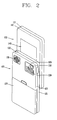
- FIG. 2 is a rear perspective view of the portable terminal of FIG. 1 .
- a second video input unit 128 may further be disposed on the rear case 122 of the second body 120.
- the second video input unit 128 faces a direction which is substantially opposite to a direction faced by the first video input unit 115 (see FIG. 1 ).
- the second video input unit 128 may be a camera having different pixels from those of the first video input unit 115.
- the first video input unit 115 may operate with relatively lower pixels (lower resolution).
- the first video input unit 115 may be useful when a user can capture his face and send it to another party during a video call or the like.
- the second video input unit 128 may operate with relatively higher pixels (higher resolution) such that it can be useful for a user to obtain higher quality pictures for later use.
- a flash 129 and a mirror 130 may be disposed adjacent to the second video input unit 128.
- the flash 129 operates in conjunction with the second video input unit 128 when taking a picture using the second video input unit 128.
- the mirror 130 can cooperate with the second video input unit 128 to allow a user to photograph himself in a self-portrait mode.
- a second audio output unit 131 may further be disposed at the rear case 122.
- the second audio output unit 131 can cooperate with the first audio output unit 114 (see Fig. 1 ) to provide stereo output.
- a broadcast signal receiving antenna 132 may be disposed at the rear case 122, as well as an antenna for call communications or the like.
- the antenna 132 may retract into the second body 120.
- a part of a slide module 133 for slidably coupling the first body 110 to the second body 120 may be disposed at the rear case 112 of the first body 110.
- slide module 133 may be disposed at the front case 121 of the second body 120, so as not to be exposed to the exterior as shown in Fig. 2 .
- the second video input unit 128 is disposed at the second body 120; however, the present invention may not be limited to the configuration. It is also possible that one or more of those components (e.g., 128 to 132), which have been described to be implemented on the rear case 122, such as the second video input unit 128, will be implemented on the first body 110, particularly, on the rear case 112. In this configuration, the component(s) disposed on the rear case 112 can be protected by the second body 120 in a closed state of the portable terminal. In addition, without the second video input unit 128, the first video input unit 115 can be implemented to be rotatable so as to rotate up to a direction which the second video input unit 128 faces.
- those components e.g., 128 to 132
- the first video input unit 115 can be implemented to be rotatable so as to rotate up to a direction which the second video input unit 128 faces.
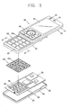
- FIG. 3 is a disassembled perspective view of the portable terminal in accordance with the one embodiment of the present invention
- FIG. 4 is a sectional view of the portable terminal taken along the line IV-IV of FIG. 3 .
- the second manipulation unit 123 may be implemented as a plurality of key buttons 123a operable in a pressing manner.
- This embodiment exemplarily illustrates that individual key buttons 123a are mounted on the second body 120; however, the second manipulation unit 123 may be implemented in a type of 'keypad' having integrally-formed key buttons 123a.
- a printed circuit board 136 having electric components, which allow operations of the portable terminal, may be mounted between the front case 121 and the rear case 122.
- This embodiment exemplarily illustrates a rigid PCB as the printed circuit board 136; however, a flexible PCB (FPCB) may also be useable.
- FPCB flexible PCB
- the printed circuit board 136 may have dome switches 140 for generating signals responsive to press inputs via the key buttons 123a.
- Push protrusions 123b by which the dome switches 140 are pushed may be formed on a rear surface of the key buttons 123a, respectively.
- the corresponding dome switch 140 is pressed by the push protrusions 123b. Also, as the dome switch 140 is transformed (i.e., pressed) to some degree, an input signal is generated.
- Illumination units 138 for illuminating the key buttons 123a may be mounted between the dome switches 140 of the printed circuit board 136.
- the illumination units 138 may be employed to illuminate numbers, characters, symbols designated on the key buttons 123a.
- the illumination unit 138 may be configured as a light emitting diode (LED) so as to reduce power loss and fabricating cost.
- LED light emitting diode
- a metal dome 143 (see FIG. 7 ) of each dome switch 140 may be attached onto the printed circuit board 136 by use of an adhesive tape having a preset area, and an example of the adhesive tape may include a light guide film for guiding light emitted from the illumination unit 138.
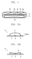
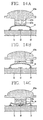
- FIGS. 5a and 5b are sectional views showing a structure and an operation state of a typical type of dome switch
- FIG. 6 is a graph showing strength of a force applied to a metal dome depending on a transformation of the metal dome.
- a dome switch 10 may include first and second conductors 12 and 13 patterned on a board 11, and a metal dome 14 for electrically connecting the first and second conductors 12 and 13 to each other when being pressed.
- the first conductor 12 may be located at a position aligned with a central portion of the metal dome 14.
- the second conductor 13 may be formed in a shape of ring or band surrounding a periphery of the first conductor 12.
- the metal dome 14 may be supported by the second conductor 13.
- the metal dome 14 is pressed in the state of FIG. 5A , the dome 14 is transformed.
- the central portion of the metal dome 14 is moved (pressed down) to be in contact with the first conductor 12.
- the first and second conductors 12 and 13 are electrically connected to each other, thereby generating an input signal.
- a distance that the central portion of the metal dome 14 is moved is referred to as a stroke.
- a horizontal axis of the graph shown in FIG. 6 indicates a stroke and a vertical axis indicates the strength of force applied onto the metal dome 14.
- the strength of force applied to the metal dome 14 increases in proportion to the stroke and decreases from a specific point.
- the strength of force at this specific point may be preferred to as a compress peak (CP) value, and buckling may occur at an edge of the metal dome 14 at this specific point.
- CP compress peak
- the force applied to the metal dome 14, which was being decreased, is then increased again from the specific point by the buckling. This is caused when the central portion of the metal dome 14 comes in contact with the first conductor 12.
- the strength of the force at this point may be referred to as a compress low (CL) value.
- the strength of the force applied to the metal dome 14 may be varied depending on a transformed degree (level) of the metal dome 12. This is transferred to a user as a type of click feeling.
- a concept of 'Click ratio' for numerically representing such click feeling may be introduced.
- the click feeling is enhanced when the click ratio is high. Comparing a first curved line I with a second curved line II shown in the graph of Fig. 6 , it can be noticed that the second curved line II has a CL value CL2 lower than a CL value CL1 of the first curved line I and additionally the second curved line II has a stroke value S2 greater than a stroke value S1 of the first curved line I.
- the second curved line II since the second curved line II has a greater difference value between CP value and CL value (i.e., CP-CL) than the first curved line I , it can be known that the second curved line II has a click ratio higher than that of the first curved line I. Hence, the click ratio can be increased by increasing the stroke value of the metal dome 14.
- the present invention provides a structure of a dome switch capable of increasing the click ratio by increasing the stroke value of the metal dome 14.
- FIG. 7 is a sectional view of a dome switch in accordance with a 1 st embodiment of the present invention.
- the dome switch 140 may include a first conductor 141 formed on one surface of the printed circuit board 136, a second conductor 142 formed at an outer periphery of the first conductor 140, and a metal dome 143 transformed responsive to the key 123a being pressed.
- the first conductor 141 may have a contact surface to be contactable with the metal dome 143 upon the transformation of the metal dome 143, and the second conductor 142 may have a support surface for supporting the metal dome 143.
- An edge of the metal dome 143 may be supported on the support surface of the second conductor 142. Upon being transformed, a central portion of the metal dome 143 may be moved to come in contact with the contact surface of the first conductor 141.
- the present invention introduces a structure in which the contact surface of the first conductor 141 is located lower than the support surface of the second conductor 142 so as to increase a stroke of the metal dome 143 upon the transformation of the metal dome 143.
- the first conductor 141 has been located lower than a principal surface 136a or an upper surface of the printed circuit board 136.
- a structure may be proposed in which a recess portion 144 is recessed into the printed circuit board 136 by a preset depth d.
- the first conductor 141 may be formed on the recess portion 144 and the second conductor 142 may be formed outside the recess portion 144.
- the first conductor 141 and the second conductor 142 may have various thicknesses depending on a height difference between the contact surface and the support surface.
- the first and second conductors 141 and 142 may have the same thickness.
- a fabrication process of the dome switch 140 will be the same to that of the existing dome switch excluding a procedure of forming the recess portion 144, thereby implementing the structure of the dome switch 140 according to the present invention without a great change in the fabrication process.
- FIG. 8 is a graph showing the measurements of forces applied to a metal dome responsive to the transformation of the metal dome of the dome switch in accordance with the 1 st embodiment of the present invention.
- a third curved line III indicates that the contact surface of the first conductor 141 and the support surface of the second conductor 142 have the same height
- a fourth curved line IV indicates that the recess portion 144 is formed at the printed circuit board 136 so that the contact surface of the first conductor 141 is located lower than the support surface of the second conductor 142.
- III IV CP(gf) 185 184 CL(gf) 100 67 Click ratio (%) 46.1 63.3 Stroke (mm) 0.274 0.295
- the click ratio is increased by 18% from 46.1 % to 63.3% when the contact surface and the support surface have a height difference of 0.002 mm. Consequently, it can be noticed that the click ratio can be remarkably increased by a slight increase in the stroke of the metal dome 143.
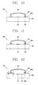
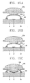
- FIG. 9 is a sectional view of a dome switch in accordance with a 2 nd embodiment of the present invention.
- a dome switch 240 may also include a first conductor 241, a second conductor 242 and a metal dome 243.
- a contact surface of the first conductor 241 may be formed at a position lower than a support surface of the second conductor 242.
- this embodiment exemplarily illustrates that the contact surface of the first conductor 241 and the support surface of the second conductor 242 are located higher than a principal surface 236a of a printed circuit board 236.
- the first and second conductors 241 and 242 may be disposed on the principal surface 236a of the printed circuit board 236. That is, the first and second conductors 241 and 242 may be disposed on the same surface of the printed circuit board 236 and the second conductor 242 may have a thickness t2 thicker than a thickness t1 of the first conductor 241.
- a structure can be implemented in which the contact surface of the first conductor 241 is formed at a position lower than the support surface of the second conductor 242.
- This embodiment can achieve a structure of increasing the stroke of the metal dome 243 without performing a process of forming a recess portion on a board.
- FIGS. 10 and 11 are sectional views of dome switches in accordance with 3 rd and 4 th embodiments of the present invention.
- the similar reference numerals have been given to the same components to those of the previous embodiment.
- Each of dome switches 340 and 440 may also have a structure in which a contact surface of a first conductor 341, 441 and a support surface of a second conductor 342, 442 is located higher than a principal surface 336a, 436a of a printed circuit board 336, 436.
- Each of the dome switches 340 and 440 may further include a supporting member 350, 450 for increasing a height of a supported point of the metal dome 343, 443.
- the supporting member 350 may be formed in a ring shape or a donut shape with a preset thickness.
- the supporting member 350 may be disposed between an upper surface of the second conductor 342 and the supported point of the metal dome 343, and made of a conductive material so as to electrically connect the second conductor 342 to the metal dome 343.
- first conductor 341, 441 have the same thickness to the second conductor 342, 442; however, different thicknesses may also be available.
- a supporting member 450 may be disposed between the second conductor 442 and the printed circuit board 436.
- the supporting member 450 employed in this embodiment may be formed either of a conductive material or of a non-conductive material.
- the supporting member 450 may be formed separately from the printed circuit board 436; however, it may be formed integrally with the printed circuit board 436.
- the supporting member 450 can be formed of an insulating material, which forms the printed circuit board 436.
- FIG. 12 is a sectional view of a dome switch in accordance with a 5 th embodiment of the present invention. Similar to the previous embodiment, in FIG. 12 , similar reference numerals have been given to the same components to those of the previous embodiment.
- a dome switch 540 is configured so that a recess portion 544 is formed at a printed circuit board 536 and a supporting member 550 is disposed at an outer periphery of the recess portion 544 so as to increase the stroke of a metal dome 543.
- the structure is achieved by additionally forming the recess portion 544 with a predetermined depth at an inner region of the supporting member 450 of the dome switch 440 according to the 4 th embodiment.
- a height of a first conductor 541 can be decreased by the depth d of the recess portion 544 and a height of a second conductor 542 can be increased by a thickness t of the supporting member 550. Consequently, a height difference between the contact surface of the first conductor 541 and the support surface of the second conductor 542 can be increased that much.
- This structure has the advantage of increasing the stroke of the metal dome 543 as much as possible even without greatly increasing the height between the lower surface of the printed circuit board 536 and the upper end of the metal dome 543.
- TRS 'tactile response slop
- FIG. 13 is a graph showing the concept of TRS, which shows the strength of forces applied to a metal dome responsive to the transformation of the metal dome.
- a horizontal axis of the graph indicates a stroke and a vertical axis thereof indicates the strength of force applied to a metal dome 14.
- TRS denotes an approximate inclination of a curved line at an interval between S1 and S2.
- FIGS. 14A to 14C and FIGS. 15A to 15C are conceptual views showing a method for increasing TRS.
- FIGS. 14A to 14C show a method for forming an elastic member 123c at an end portion of the push protrusion 123b as an example of increasing TRS.
- the elastic member 123c may be formed of rubber or silicon.
- the elastic member 123c may be compressed.
- buckling may be generated at an edge of the metal dome 14.
- the following table shows measurements of CP value, click ratio, stroke and TRS according to a length of the elastic member 123c. 0(mm) 0.2(mm) 0.4(mm) 0.6(mm) 0.8(mm) 1.0(mm) CP(gf) 210 212 218 223 225 226 Click ratio (%) 55.5 56.1 56.1 56.6 56.9 54.0 Stroke (mm) 0.210 0.236 0.262 0.285 0.311 0.337 TRS 1209 1258 1547 2074 2954 3944
- TRS value has been more increased upon employing the elastic member 123c than upon not employing the elastic member 123c. It can also be noticed that the increase in the length of the elastic member 123c proportionally causes the increase in the TRS value.
- FIGS. 15A to 15C show a method for elastically moving a supported point of the metal dome 14 as another method for increasing TRS..
- a dome switch may include an elastic supporting member 160 for elastically supporting the metal dome 14.
- the elastic supporting member 160 may be formed of a conductive material and have an elastic index smaller than that of the metal dome 14.
- the elastic supporting member 160 may be compressed.
- buckling may be generated at an edge of the metal dome 14.
- This method has an advantage of implementing a stable structure of the dome switch and achieving a TRS-increased structure without greatly affecting the thickness of the terminal.
- description will be given of embodiments focusing on such structure.
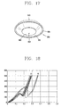
- FIGS. 16A to 16C are sectional views of a dome switch in accordance with a 6 th embodiment of the present invention
- FIG. 17 is a perspective view of an elastic supporting member shown in FIGS. 16A to 16C .
- a dome switch 640 may include a plurality of conductors 641 and 642 patterned on a printed circuit board 636, a metal dome 643 transformed responsive to the key button 123a being pressed so as to electrically connect the conductors 641 and 642, and an elastic supporting member 660 for supporting the metal dome 643 and elastically moving a supported point of the metal dome 643 when the key button 123a is pressed.
- the conductors 641 and 642 may include a first conductor 641 located at a central portion and a second conductor 642 formed at an outer periphery of the first conductor 641.
- the first and second conductors 641 and 642 may be formed on an upper surface of the printed circuit board 636.
- the first and second conductors 641 and 642 may be disposed at a recess portion 637 recessed into the printed circuit board 636 by a predetermined depth. This structure allows the use of the elastic supporting member 660 to affect the thickness of the portable terminal as less as possible.
- the metal dome 643 is maintained in the state of being electrically connected to the second conductor 642.
- the push protrusion 123b in turn pushes the metal dome 643, which is accordingly transformed. Consequently, the metal dome 643 contacts the first conductor 641 so as to electrically connect the first and second conductors 641 and 642 to each other.
- This embodiment exemplarily illustrates, as shown in FIG. 17 , that the elastic supporting member 660 is implemented in a type of washer having an inclination surface in a radial direction.
- the elastic supporting member 660 may be implemented in any type or form if it can elastically support a supported point of the metal dome 643.
- the elastic supporting member 660 may be disposed between the metal dome 643 and the second conductor 642.
- the elastic supporting member 660 may be formed of a conductive material so as to electrically connect the metal dome 643 to the second conductor 642.
- the elastic supporting member 660 may include a first supporting portion 661 for supporting the periphery of an edge of the metal dome 643, and a second supporting portion 662 extending from the first supporting member 661 and supported by the second conductor 642.
- the first supporting portion 661 may be provided with a stopping protrusion 664 stopped at a supported point of the metal dome 643.
- the stopping protrusion 664 may be implemented by forming a stepped portion at an upper surface of the elastic supporting member 660.
- the second supporting portion 662 may extend from the first supporting portion 661 to be inclined in a radial direction of the metal dome 643.
- the second supporting portion 662 may be supported by the second conductor 642 in a state of not being attached or fixed onto the second conductor 642 as shown in this embodiment; however, it may be attached or fixed onto the second conductor 642.
- the second supporting portion 642 may be integrally formed with the second conductor 642 by being made of the same material to that of the second conductor 642.
- a through hole 663 through which the central portion of the metal dome 643 comes in contact with the first conductor 641 upon the transformation of the metal dome 643 may be formed through the central region of the elastic supporting member 660, namely, inside the second supporting portion 662.
- the elastic supporting member 660 is transformed close to the upper surface of the printed circuit board 636.
- the metal dome 643 is kept pressed so as to be transformed at a central portion thereof.
- the elastic supporting member 660 is restored to the original state.
- the restoring force of the elastic supporting member 660 and the force applied by the push protrusion 123b causes buckling at the edge of the metal dome 643.
- the operation of such dome switch 640 may increase TRS as described above.
- FIG. 18 is a graph showing comparison results of forces applied to a metal dome before and after employing the elastic supporting member.
- the left graph V of FIG. 18 represents the results before employing the elastic supporting member 660, and the right graph VI represent the results after employing the elastic supporting member 660.
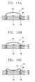
- FIGS. 19A to 19C are sectional views showing a dome switch in accordance with a 7 th embodiment of the present invention. These drawings represent similar reference numerals to the same components to those in the previous embodiments.
- a dome switch 740 may include a plurality of conductors 741 and 742 patterned on a printed circuit board 736, a metal dome 743 transformed when the key button 123a is pressed so as to electrically connect the conductors 741 and 742, and an elastic supporting member 760 for supporting the metal dome 743 and elastically moving a supported point of the metal dome 743 when the key button 123a is pressed.
- the conductors 741 and 742 according to this embodiment may also include the first conductor 741 and the second conductor 742.
- This embodiment exemplarily illustrates a structure in which the first conductor 741 is formed at an upper surface of the printed circuit board 736 and the second conductor 742 is formed inside the printed circuit board 736.
- the elastic supporting member 760 may be implemented as a metallic spring 760 for supporting an edge of the metal dome 743.
- the spring 760 may be electrically connected to the second conductor 742 within the printed circuit board 736.
- the printed circuit board 736 may include a recess portion 737 with a predetermined depth.
- the recess portion 737 may be formed at an outer periphery of the first conductor 741, and the second conductor 742 may be disposed in the recess portion 737.
- the spring 760 may be a type of coil spring inserted into the recess portion 737, and have one end supported by the second conductor 742 and another end supporting a supported point of the metal dome 743.
- a ring-shaped metallic member 766 may further be mounted between the supported point of the metal dome 743 and the spring 760.
- the spring 760 may be compressed by a force that the push protrusion 123b presses the metal dome 743. Also, as the metal dome 743 is kept pressed, the central portion of the metal dome 743 may also be transformed.
- the spring 760 When the metal dome 743 is transformed more than a preset level, the spring 760 extends to its original state as shown in FIG. 19C .
- buckling may be generated at the edge of the metal dome 243 by the restoring force of the spring 760 and the force applied by the push protrusion 123b. Consequently, the operation of the dome switch is transferred to a user in a type of click feeling.
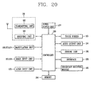
- FIG. 20 is a block diagram showing a portable terminal in accordance with one embodiment of the present invention.
- the portable terminal may includes components, such as a wireless communication unit 181, manipulation units 116, 123 and 124, video input units 115 and 128, an audio input unit 125, a display 113, audio output units 114 and 131, a sensing unit 186, an interface unit 126, a broadcast receiving module 185, a memory 184, a power supply unit 127 and a controller 180.
- a wireless communication unit 181 manipulation units 116, 123 and 124, video input units 115 and 128, an audio input unit 125, a display 113, audio output units 114 and 131, a sensing unit 186, an interface unit 126, a broadcast receiving module 185, a memory 184, a power supply unit 127 and a controller 180.
- the controller 180 typically controls the overall operations of the portable terminal.
- the controller 180 may perform related control and processing for voice call communication, data communication, telephony communication and the like.
- the wireless communication module 181 may transmit and receive radio signals with a mobile communication base station via an antenna.
- the wireless communication module 181 manages transmission and reception of audio data, text data, video data and control data under the control of the controller 180.
- the wireless communication module 181 may include a transmitting unit 182 for modulating and transmitting a signal to be sent, and a receiving unit 183 for demodulating a signal received.
- the manipulation units 116, 123, 124 may be configured, as shown in Fig. 1 , thus to provide the controller 180 with key input data input by a user to control the operations of the portable terminal.
- the manipulation units 116, 123, 124 may include a dome switch, a touchpad (e.g., static pressure/capacitance), a jog wheel, a jog switch and the like.
- the video input units 115 and 128 process image frames of still images or video obtained by an image sensor in a video call mode or a capturing mode. Such processed image frames are converted into image data displayable on the display 113 to be then output on the display 113.
- the image frames processed by the video input units 115 and 128 may be stored in the memory 184 under the control of the controller 180 or be sent to the exterior via the wireless communication module 181.
- the audio input unit 125 receives an external audio signal via a microphone while the portable terminal is in a particular mode, such as phone call mode, recording mode and voice recognition. This audio signal is processed and converted into digital data. Such processed digital data is converted into a data format transmittable to a mobile communication base station via the wireless communication module 181 when the portable terminal is in the phone call mode, and then outputted to the wireless communication module 181. The processed digital data may be stored in the memory 184 in a recording mode.
- the audio input unit 125 may include assorted noise removing algorithms to remove noise generated in the course of receiving the external audio signal.
- the display 113 displays information processed in the portable terminal. For example, when the portable terminal is in a phone call mode, the display 113 displays User Interface (UI) or (Graphic User Interface (GUI) related to the call under the control of the controller 180. If the portable terminal operates in a telephony call mode or capturing mode, the captured image or UI or GUI may be displayed under the control of the controller 180. If the display 113 includes a touch screen, it may be used as an input device as well as an output device.
- UI User Interface
- GUI Graphic User Interface
- the audio output units 114 and 131 may convert audio data received from the wireless communication module 181 or audio data stored in the memory 184 under the control of the controller 180 when the portable terminal is in the call-receiving mode, a phone call mode, a recording mode, a voice recognition mode, or a broadcast receiving mode. Such converted audio data is then outputted to the exterior.
- the audio output units 114 and 131 also output an audio signal associated with a function (e.g., outputting a call receiving sound, a message receiving sound, or the like) performed in the portable terminal.
- a function e.g., outputting a call receiving sound, a message receiving sound, or the like
- Such audio output units 114 and 131 may include a speaker, a receiver, a buzzer and the like.
- the sensing unit 186 provides status measurements of various aspects of the portable terminal.
- the sensing unit 166 may detect an open/close status of the portable terminal, a change of position of the portable terminal or a component of the portable terminal, a presence or absence of user contact with the portable terminal and the like, thereby generating a sensing signal for controlling the operation of the portable terminal.
- the sensing unit 186 senses the open or closed state of a slide type portable terminal, and outputs the sensed result to the controller 180, such that the operation of the portable terminal can be controlled.
- Other examples include the sensing unit 186 sensing the presence or absence of power provided by the power supply 127, the presence or absence of a coupling or other connection between the interface 126 and an external device.
- the interface 126 is often implemented to couple the portable terminal with external devices.
- Typical external devices include wired/wireless headphones, external chargers, wired/wireless data ports, card sockets (e.g., memory card, SIM/UIM card or the like) and the like.
- the interface 126 may allow the portable terminal to receive data or power from external devices and transfer such data or power to each component inside the portable terminal, or transmit internal data of the portable terminal to external devices.
- the memory 184 may store a program for the control and processing of the controller 180, or temporarily store input/output data (e.g., phone book data, messages, still images, video or the like).
- input/output data e.g., phone book data, messages, still images, video or the like.
- the memory 184 may store a program for controlling the operation of the portable terminal according to the present invention.
- the memory 184 may include typically known hard disk, a card-type memory (e.g., SD or XD memory), a flash memory, RAM, ROM and the like.
- a card-type memory e.g., SD or XD memory
- flash memory e.g., RAM, ROM and the like.
- the broadcast receiving module 185 may receive a broadcast signal transmitted via satellites or terrestrial waves and convert such broadcast signal into a broadcast data format capable of being output to the audio output units 114 and 131 and the display 113 so as to output the converted signal to the controller 180.
- the broadcast receiving module 185 may also receive additional data associated with broadcasting (e.g., Electric Program Guide (EPG), channel list, or the like).
- EPG Electric Program Guide
- the broadcast data converted in the broadcast receiving module 185 and the additional data may be stored in the memory 184.
- the power supply 127 provides power required by the various components for the portable terminal.
- the provided power may be internal power, external power, or combinations thereof.
- the present invention provides a dome switch configured so that a contact surface of a first conductor is located lower than a support surface of a second conductor so as to increase a stroke upon transformation of a metal dome, thereby increasing click ratio, resulting in providing enhanced click feeling.
- the present invention provides a dome switch configured so that a structure of elastically moving a supported point of a metal dome upon transformation of the metal dome is implemented to thus improve TRS of the metal dome, resulting in providing enhanced click feeling.
Landscapes
- Push-Button Switches (AREA)
- Telephone Set Structure (AREA)
Abstract
Description
- The present invention relates to a portable terminal having a dome switch with an enhanced click feeling.
- Portable terminals can be easily carried and have one or more of functions such as supporting voice and video telephony calls, inputting and/or outputting information, storing data and the like.
- As it becomes multifunctional, the portable terminal can be allowed to capture still images or moving images, play music or video files, play games, receive broadcast and the like, so as to be implemented as an integrated multimedia player.
- Various new attempts have been made for the multimedia devices by hardware or software in order to implement such complicated functions. For example, a user interface environment is provided in order for users to easily and conveniently retrieve or select functions.
- A portable terminal has input devices for inputting information by a user's manipulation. Such an input device may be implemented as a dome switch or a touch pad which allows a user to input commands or information by pushing or touching the same, or a wheel, a jog or a joystick manipulated in a manner of rotating keys.
- Among others, the dome switch has a simple reliable structure and provides a user with click feeling. Such advantages render the dome switch most typically employed in the portable terminal.
- Therefore, an object of the present invention is to provide a structure of a dome switch capable of enhancing user's click feeling upon pressing a keypad.
- To achieve these and other advantages and in accordance with the purpose of the present invention, as embodied and broadly described herein, there is provided a portable terminal including, a first conductor formed on one surface of a board and having a contact surface, a second conductor formed at an outer periphery of the first conductor and having a support surface, and a metal dome supported by the support surface and transformed responsive to a key being pressed so as to contact the contact surface, wherein the contact surface is located at a position lower than the support surface so as to increase a transformation stroke of the metal dome.
- In another aspect of the present invention, there is provided a portable terminal including, a first conductor patterned on a board, a second conductor patterned on an outer periphery of the first conductor, a metal dome electrically connected to the second conductor and transformed responsive to a key being pressed so as to contact the first conductor, and an elastic supporting member configured to support a supported point of the metal dome in a state of being supported by the second conductor, and elastically move the support point of the metal dome when the key is pressed.
- The foregoing and other objects, features, aspects and advantages of the portable terminal according to the present invention will become more apparent from the following detailed description of the present invention when taken in conjunction with the accompanying drawings.
- The accompanying drawings, which are included to provide a further understanding of the invention and are incorporated in and constitute a part of this specification, illustrate embodiments of the invention and together with the description serve to explain the principles of the invention.
- In the drawings:
-
FIG. 1 is a front perspective view of a portable terminal in accordance with one embodiment of the present invention; -
FIG. 2 is a rear perspective view of the portable terminal in accordance with the one embodiment of the present invention; -
FIG. 3 is a disassembled perspective view of the portable terminal in accordance with the one embodiment of the present invention; -
FIG. 4 is a sectional view of the portable terminal taken along the line IV-IV ofFIG. 3 ; -
FIGS. 5A and 5B are sectional views showing a structure and an operation state of a typical type of dome switch; -
FIG. 6 is a graph showing strength of force applied to a metal dome depending on a transformation of the metal dome; -
FIG. 7 is a sectional view of a dome switch in a 1st embodiment of the present invention; -
FIG. 8 is a graph showing the measurements of forces applied to a metal dome responsive to the transformation of the metal dome of the dome switch in accordance with the 1st embodiment of the present invention; -
FIGS. 9 to 12 are sectional views showing dome switches in accordance with 2nd to 5th embodiments of the present invention; -
FIG. 13 is a graph showing a concept of tactile response slope (TRS); -
FIGS. 14A to 14C are conceptual views showing one embodiment of a method for increasing TRS; -
FIGS. 15A to 15C are conceptual views showing another embodiment of a method for increasing TRS; -
FIGS. 16A to 16C are sectional views showing a dome switch in accordance with a 6th embodiment of the present invention; -
FIG. 17 is a perspective view showing an elastic supporting member shown inFIGS. 16a to 16c ; -
FIG. 18 is a graph showing comparison results of forces applied to a metal dome before and after employing the elastic supporting member; -
FIGS. 19A to 19C are sectional views showing a dome switch in accordance with a 7th embodiment of the present invention; -
FIG. 20 is a block diagram showing a portable terminal in accordance with one embodiment of the present invention. - Description will now be given in detail of a portable terminal in accordance with the preferred embodiments of the present invention, with reference to the accompanying drawings.
-
FIG. 1 is a front perspective view of aportable terminal 100 in accordance with one embodiment of the present invention. - A
portable terminal 100 may include afirst body 110 and asecond body 120 slidable to thefirst body 110 in at least one direction. Here, this embodiment illustrates a slide type portable terminal; however, the present invention may not be limited to the configuration. The present invention may also be applicable to various types of portable terminals, such as bar type, folder type, swing type, swivel type and the like. - The state where the
first body 110 is positioned over thesecond body 120 may be referred to as a closed configuration (position). Also, the state where thefirst body 110 exposes at least part of thesecond body 120, as shown inFIG. 1 , can be referred to as an open configuration (position). - In addition, the
portable terminal 100 may typically be operable in a standby (idle) mode when in the closed configuration, but this mode can be released by the user's manipulation. Also, theportable terminal 100 may be operable in an active (phone call) mode in the open configuration. This mode may also be changed into the idle mode according to the user's manipulation or after a certain time elapses. - A case (housing, casing, cover, etc.) forming the outside of the
first body 110 is formed by afront case 111 and arear case 112. In addition, various electronic components may be disposed in a space between thefront case 111 and therear case 112. - At least one intermediate case may additionally be disposed between the
front case 111 and therear case 112. - Further, the cases can be formed of resin in a manner of injection molding, or formed using metallic materials such as stainless steel (STS) and titanium (Ti).
- A
display 113, anaudio output unit 114, a firstvideo input unit 115 or afirst manipulation unit 116 may be disposed on thefirst body 110, in detail, on thefront case 111. - The
display 113 may be configured to display visible information, examples of which include a liquid crystal display (LCD) module, an organic light emitting diodes (OLED) module and the like. Thedisplay 113 may further include a touch screen so as to allow a user to input information by a touch input. - The
audio output unit 114 may be configured as a receiver or a speaker. The firstvideo input unit 115 may be a camera module for allowing a user to capture images or video. - The
first manipulation unit 116 may receive a command input to control the operation of theportable terminal 100 according to the one embodiment of the present invention. - Similar to the
first body 110, afront case 121 and arear case 122 may configure a case of thesecond body 120. Asecond manipulation unit 123 may be disposed at thesecond body 120, more particularly, at a front face of thefront case 121. - A
third manipulation unit 124, anaudio input unit 125 and aninterface 126 may be disposed on at least one of thefront case 121 or therear case 122. - The first to
third manipulation unit - For example, the manipulation portion can be implemented as a dome switch or touchpad which can receive information or commands input by a user in a pushing or touching manner, or implemented in a manner of using a wheel, a jog or a joystick to rotate keys.
- Regarding each function, the
first manipulation unit 116 can be used for inputting commands such as START, END, SCROLL or the like, and thesecond manipulation unit 123 can be used for inputting numbers, characters, symbols, or the like. Also, thethird manipulation unit 124 can function as a hot key for activating a specific function, such as activation of the firstvideo input unit 115. - The
audio input unit 125 may be configured as a microphone so as to receive user's voice, other sounds and the like. - The
interface 126 may interface theportable terminal 100 and external devices so as to allow data exchange therebetween or the like. For example, theinterface 126 may be at least one of a wired/wireless access terminal for earphones, a short-range communication port (e.g., IrDA port, BLUETOOTH port, wireless Lan port, and the like), and power supply terminals for supplying power to the portable terminal. - The
interface 126 may be a card socket for accommodating an external card such as Subscriber Identification Module (SIM), User Identity Module (UIM), memory card for storing information, or the like. - A
power supply unit 127 for supplying power to theportable terminal 100 may be mounted in therear case 122. For example, thepower supply unit 127 may be a rechargeable battery so as to be detachable for charging. -
FIG. 2 is a rear perspective view of the portable terminal ofFIG. 1 . - Referring to
FIG. 2 , a secondvideo input unit 128 may further be disposed on therear case 122 of thesecond body 120. The secondvideo input unit 128 faces a direction which is substantially opposite to a direction faced by the first video input unit 115 (seeFIG. 1 ). Also, the secondvideo input unit 128 may be a camera having different pixels from those of the firstvideo input unit 115. - For instance, the first
video input unit 115 may operate with relatively lower pixels (lower resolution). Thus, the firstvideo input unit 115 may be useful when a user can capture his face and send it to another party during a video call or the like. On the other hand, the secondvideo input unit 128 may operate with relatively higher pixels (higher resolution) such that it can be useful for a user to obtain higher quality pictures for later use. - A
flash 129 and a mirror 130 may be disposed adjacent to the secondvideo input unit 128. Theflash 129 operates in conjunction with the secondvideo input unit 128 when taking a picture using the secondvideo input unit 128. The mirror 130 can cooperate with the secondvideo input unit 128 to allow a user to photograph himself in a self-portrait mode. - A second
audio output unit 131 may further be disposed at therear case 122. - The second
audio output unit 131 can cooperate with the first audio output unit 114 (seeFig. 1 ) to provide stereo output. - Also, at the
rear case 122 may be disposed a broadcastsignal receiving antenna 132, as well as an antenna for call communications or the like. Theantenna 132 may retract into thesecond body 120. - A part of a slide module 133 for slidably coupling the
first body 110 to thesecond body 120 may be disposed at therear case 112 of thefirst body 110. - Another part of the slide module 133 may be disposed at the
front case 121 of thesecond body 120, so as not to be exposed to the exterior as shown inFig. 2 . - As described above, it has been described that the second
video input unit 128 is disposed at thesecond body 120; however, the present invention may not be limited to the configuration. It is also possible that one or more of those components (e.g., 128 to 132), which have been described to be implemented on therear case 122, such as the secondvideo input unit 128, will be implemented on thefirst body 110, particularly, on therear case 112. In this configuration, the component(s) disposed on therear case 112 can be protected by thesecond body 120 in a closed state of the portable terminal. In addition, without the secondvideo input unit 128, the firstvideo input unit 115 can be implemented to be rotatable so as to rotate up to a direction which the secondvideo input unit 128 faces. -
FIG. 3 is a disassembled perspective view of the portable terminal in accordance with the one embodiment of the present invention, andFIG. 4 is a sectional view of the portable terminal taken along the line IV-IV ofFIG. 3 . - The
second manipulation unit 123 according to the present invention may be implemented as a plurality ofkey buttons 123a operable in a pressing manner. This embodiment exemplarily illustrates that individualkey buttons 123a are mounted on thesecond body 120; however, thesecond manipulation unit 123 may be implemented in a type of 'keypad' having integrally-formedkey buttons 123a. - A printed
circuit board 136 having electric components, which allow operations of the portable terminal, may be mounted between thefront case 121 and therear case 122. This embodiment exemplarily illustrates a rigid PCB as the printedcircuit board 136; however, a flexible PCB (FPCB) may also be useable. - The printed
circuit board 136 may havedome switches 140 for generating signals responsive to press inputs via thekey buttons 123a. Pushprotrusions 123b by which the dome switches 140 are pushed may be formed on a rear surface of thekey buttons 123a, respectively. Upon pressing akey button 123a, the correspondingdome switch 140 is pressed by thepush protrusions 123b. Also, as thedome switch 140 is transformed (i.e., pressed) to some degree, an input signal is generated. -
Illumination units 138 for illuminating thekey buttons 123a may be mounted between the dome switches 140 of the printedcircuit board 136. Theillumination units 138 may be employed to illuminate numbers, characters, symbols designated on thekey buttons 123a. Theillumination unit 138 may be configured as a light emitting diode (LED) so as to reduce power loss and fabricating cost. - A metal dome 143 (see
FIG. 7 ) of eachdome switch 140 may be attached onto the printedcircuit board 136 by use of an adhesive tape having a preset area, and an example of the adhesive tape may include a light guide film for guiding light emitted from theillumination unit 138. -
FIGS. 5a and 5b are sectional views showing a structure and an operation state of a typical type of dome switch, andFIG. 6 is a graph showing strength of a force applied to a metal dome depending on a transformation of the metal dome. - Referring to
FIGS. 5a and 5b , adome switch 10 may include first andsecond conductors board 11, and ametal dome 14 for electrically connecting the first andsecond conductors - The
first conductor 12 may be located at a position aligned with a central portion of themetal dome 14. Thesecond conductor 13 may be formed in a shape of ring or band surrounding a periphery of thefirst conductor 12. Themetal dome 14 may be supported by thesecond conductor 13. - If the
metal dome 14 is pressed in the state ofFIG. 5A , thedome 14 is transformed. Thus, as shown inFIG. 5B , the central portion of themetal dome 14 is moved (pressed down) to be in contact with thefirst conductor 12. Accordingly, the first andsecond conductors metal dome 14 is moved is referred to as a stroke. - A horizontal axis of the graph shown in
FIG. 6 indicates a stroke and a vertical axis indicates the strength of force applied onto themetal dome 14. - As shown in the graph of
FIG. 6 , the strength of force applied to themetal dome 14 increases in proportion to the stroke and decreases from a specific point. The strength of force at this specific point may be preferred to as a compress peak (CP) value, and buckling may occur at an edge of themetal dome 14 at this specific point. - The force applied to the
metal dome 14, which was being decreased, is then increased again from the specific point by the buckling. This is caused when the central portion of themetal dome 14 comes in contact with thefirst conductor 12. The strength of the force at this point may be referred to as a compress low (CL) value. - As such, the strength of the force applied to the
metal dome 14 may be varied depending on a transformed degree (level) of themetal dome 12. This is transferred to a user as a type of click feeling. A concept of 'Click ratio' for numerically representing such click feeling may be introduced. Here, the 'click ratio' may be represented in the following formula.
- Typically, it has been known that the click feeling is enhanced when the click ratio is high. Comparing a first curved line I with a second curved line II shown in the graph of
Fig. 6 , it can be noticed that the second curved line II has a CL value CL2 lower than a CL value CL1 of the first curved line I and additionally the second curved line II has a stroke value S2 greater than a stroke value S1 of the first curved line I. - That is, since the second curved line II has a greater difference value between CP value and CL value (i.e., CP-CL) than the first curved line I , it can be known that the second curved line II has a click ratio higher than that of the first curved line I. Hence, the click ratio can be increased by increasing the stroke value of the
metal dome 14. - The present invention provides a structure of a dome switch capable of increasing the click ratio by increasing the stroke value of the
metal dome 14. -
FIG. 7 is a sectional view of a dome switch in accordance with a 1st embodiment of the present invention. - As shown in
FIG. 7 , thedome switch 140 may include afirst conductor 141 formed on one surface of the printedcircuit board 136, asecond conductor 142 formed at an outer periphery of thefirst conductor 140, and ametal dome 143 transformed responsive to the key 123a being pressed. - The
first conductor 141 may have a contact surface to be contactable with themetal dome 143 upon the transformation of themetal dome 143, and thesecond conductor 142 may have a support surface for supporting themetal dome 143. - An edge of the
metal dome 143 may be supported on the support surface of thesecond conductor 142. Upon being transformed, a central portion of themetal dome 143 may be moved to come in contact with the contact surface of thefirst conductor 141. - The present invention introduces a structure in which the contact surface of the
first conductor 141 is located lower than the support surface of thesecond conductor 142 so as to increase a stroke of themetal dome 143 upon the transformation of themetal dome 143. - In order to implement the structure of this embodiment, the
first conductor 141 has been located lower than aprincipal surface 136a or an upper surface of the printedcircuit board 136. - As one example of this structure, a structure may be proposed in which a recess portion 144 is recessed into the printed
circuit board 136 by a preset depth d. Thefirst conductor 141 may be formed on the recess portion 144 and thesecond conductor 142 may be formed outside the recess portion 144. - The
first conductor 141 and thesecond conductor 142 may have various thicknesses depending on a height difference between the contact surface and the support surface. - In accordance with this embodiment, the first and
second conductors dome switch 140 will be the same to that of the existing dome switch excluding a procedure of forming the recess portion 144, thereby implementing the structure of thedome switch 140 according to the present invention without a great change in the fabrication process. -
FIG. 8 is a graph showing the measurements of forces applied to a metal dome responsive to the transformation of the metal dome of the dome switch in accordance with the 1st embodiment of the present invention. - In
FIG. 8 , a third curved line III indicates that the contact surface of thefirst conductor 141 and the support surface of thesecond conductor 142 have the same height, and a fourth curved line IV indicates that the recess portion 144 is formed at the printedcircuit board 136 so that the contact surface of thefirst conductor 141 is located lower than the support surface of thesecond conductor 142. The measurement values of the third curved line III and the fourth curved line IV are represented in the following table.III IV CP(gf) 185 184 CL(gf) 100 67 Click ratio (%) 46.1 63.3 Stroke (mm) 0.274 0.295 - Referring to the measurement results, it can be seen that the click ratio is increased by 18% from 46.1 % to 63.3% when the contact surface and the support surface have a height difference of 0.002 mm. Consequently, it can be noticed that the click ratio can be remarkably increased by a slight increase in the stroke of the
metal dome 143. -
FIG. 9 is a sectional view of a dome switch in accordance with a 2nd embodiment of the present invention. - A
dome switch 240 according to this embodiment may also include afirst conductor 241, asecond conductor 242 and ametal dome 243. A contact surface of thefirst conductor 241 may be formed at a position lower than a support surface of thesecond conductor 242. The similar reference numerals have been given inFIG. 9 to the same components to those of the previous embodiment. - Unlike the previous embodiment, this embodiment exemplarily illustrates that the contact surface of the
first conductor 241 and the support surface of thesecond conductor 242 are located higher than aprincipal surface 236a of a printedcircuit board 236. - The first and
second conductors principal surface 236a of the printedcircuit board 236. That is, the first andsecond conductors circuit board 236 and thesecond conductor 242 may have a thickness t2 thicker than a thickness t1 of thefirst conductor 241. - Accordingly, a structure can be implemented in which the contact surface of the
first conductor 241 is formed at a position lower than the support surface of thesecond conductor 242. This embodiment can achieve a structure of increasing the stroke of themetal dome 243 without performing a process of forming a recess portion on a board. -
FIGS. 10 and 11 are sectional views of dome switches in accordance with 3rd and 4th embodiments of the present invention. InFIGS. 10 and 11 , the similar reference numerals have been given to the same components to those of the previous embodiment. - Each of dome switches 340 and 440 according to these embodiments may also have a structure in which a contact surface of a
first conductor second conductor principal surface circuit board - Each of the dome switches 340 and 440 according to these embodiments may further include a supporting
member metal dome - Referring to
FIG. 10 , the supportingmember 350 may be formed in a ring shape or a donut shape with a preset thickness. The supportingmember 350 may be disposed between an upper surface of thesecond conductor 342 and the supported point of themetal dome 343, and made of a conductive material so as to electrically connect thesecond conductor 342 to themetal dome 343. - These embodiments illustrate that the
first conductor second conductor - Referring to
FIG. 11 , a supportingmember 450 may be disposed between thesecond conductor 442 and the printedcircuit board 436. The supportingmember 450 employed in this embodiment may be formed either of a conductive material or of a non-conductive material. - This embodiment exemplarily illustrates that the supporting
member 450 may be formed separately from the printedcircuit board 436; however, it may be formed integrally with the printedcircuit board 436. In this case, the supportingmember 450 can be formed of an insulating material, which forms the printedcircuit board 436. -
FIG. 12 is a sectional view of a dome switch in accordance with a 5th embodiment of the present invention. Similar to the previous embodiment, inFIG. 12 , similar reference numerals have been given to the same components to those of the previous embodiment. - A
dome switch 540 according to this embodiment is configured so that arecess portion 544 is formed at a printedcircuit board 536 and a supportingmember 550 is disposed at an outer periphery of therecess portion 544 so as to increase the stroke of ametal dome 543. The structure is achieved by additionally forming therecess portion 544 with a predetermined depth at an inner region of the supportingmember 450 of thedome switch 440 according to the 4th embodiment. - With this structure, a height of a
first conductor 541 can be decreased by the depth d of therecess portion 544 and a height of asecond conductor 542 can be increased by a thickness t of the supportingmember 550. Consequently, a height difference between the contact surface of thefirst conductor 541 and the support surface of thesecond conductor 542 can be increased that much. - This structure has the advantage of increasing the stroke of the
metal dome 543 as much as possible even without greatly increasing the height between the lower surface of the printedcircuit board 536 and the upper end of themetal dome 543. - As described above, the structures capable of enhancing the click ratio by increasing the stroke of the metal dome have been illustrated. Meanwhile, besides the click ratio, 'tactile response slop (TRS)' may be introduced as another concept for numerically representing click feeling.
-
FIG. 13 is a graph showing the concept of TRS, which shows the strength of forces applied to a metal dome responsive to the transformation of the metal dome. A horizontal axis of the graph indicates a stroke and a vertical axis thereof indicates the strength of force applied to ametal dome 14. - Here, TRS may be represented as the following formula;

where the CP value and the CL value are the same as those shown inFIG. 6 , and S1 and S2 denote strokes corresponding to the CP value and the CL value, respectively. TRS denotes an approximate inclination of a curved line at an interval between S1 and S2. - It has generally been known that as TRS increases, click feeling is enhanced.
-
FIGS. 14A to 14C andFIGS. 15A to 15C are conceptual views showing a method for increasing TRS. -
FIGS. 14A to 14C show a method for forming anelastic member 123c at an end portion of thepush protrusion 123b as an example of increasing TRS. Here, theelastic member 123c may be formed of rubber or silicon. - As the
push protrusion 123b is lowered responsive to thekey button 123a being pressed, theelastic member 123c may be compressed. When the compressedelastic member 123c is restored to its original state, buckling may be generated at an edge of themetal dome 14. - The following table shows measurements of CP value, click ratio, stroke and TRS according to a length of the elastic member 123c.
0(mm) 0.2(mm) 0.4(mm) 0.6(mm) 0.8(mm) 1.0(mm) CP(gf) 210 212 218 223 225 226 Click ratio (%) 55.5 56.1 56.1 56.6 56.9 54.0 Stroke (mm) 0.210 0.236 0.262 0.285 0.311 0.337 TRS 1209 1258 1547 2074 2954 3944 - Referring to the table, it can be seen that TRS value has been more increased upon employing the
elastic member 123c than upon not employing theelastic member 123c. It can also be noticed that the increase in the length of theelastic member 123c proportionally causes the increase in the TRS value. -
FIGS. 15A to 15C show a method for elastically moving a supported point of themetal dome 14 as another method for increasing TRS.. - To this end, a dome switch may include an elastic supporting
member 160 for elastically supporting themetal dome 14. Here, the elastic supportingmember 160 may be formed of a conductive material and have an elastic index smaller than that of themetal dome 14. - As the
push protrusion 123b is lowered responsive to thekey button 123a being pressed, the elastic supportingmember 160 may be compressed. When the compressed elastic supportingmember 160 is restored to its original state, buckling may be generated at an edge of themetal dome 14. - This method has an advantage of implementing a stable structure of the dome switch and achieving a TRS-increased structure without greatly affecting the thickness of the terminal. Hereinafter, description will be given of embodiments focusing on such structure.
-
FIGS. 16A to 16C are sectional views of a dome switch in accordance with a 6th embodiment of the present invention, andFIG. 17 is a perspective view of an elastic supporting member shown inFIGS. 16A to 16C . - A
dome switch 640 according to this embodiment may include a plurality ofconductors circuit board 636, ametal dome 643 transformed responsive to thekey button 123a being pressed so as to electrically connect theconductors member 660 for supporting themetal dome 643 and elastically moving a supported point of themetal dome 643 when thekey button 123a is pressed. - According to this embodiment, the
conductors first conductor 641 located at a central portion and asecond conductor 642 formed at an outer periphery of thefirst conductor 641. Here, the first andsecond conductors circuit board 636. - The first and
second conductors recess portion 637 recessed into the printedcircuit board 636 by a predetermined depth. This structure allows the use of the elastic supportingmember 660 to affect the thickness of the portable terminal as less as possible. - The
metal dome 643 is maintained in the state of being electrically connected to thesecond conductor 642. When thekey button 123a is pressed, thepush protrusion 123b in turn pushes themetal dome 643, which is accordingly transformed. Consequently, themetal dome 643 contacts thefirst conductor 641 so as to electrically connect the first andsecond conductors - This embodiment exemplarily illustrates, as shown in
FIG. 17 , that the elastic supportingmember 660 is implemented in a type of washer having an inclination surface in a radial direction. However, the elastic supportingmember 660 may be implemented in any type or form if it can elastically support a supported point of themetal dome 643. - The elastic supporting
member 660 may be disposed between themetal dome 643 and thesecond conductor 642. The elastic supportingmember 660 may be formed of a conductive material so as to electrically connect themetal dome 643 to thesecond conductor 642. The elastic supportingmember 660 may include a first supportingportion 661 for supporting the periphery of an edge of themetal dome 643, and a second supportingportion 662 extending from the first supportingmember 661 and supported by thesecond conductor 642. - The first supporting
portion 661 may be provided with a stoppingprotrusion 664 stopped at a supported point of themetal dome 643. The stoppingprotrusion 664 may be implemented by forming a stepped portion at an upper surface of the elastic supportingmember 660. - The second supporting
portion 662 may extend from the first supportingportion 661 to be inclined in a radial direction of themetal dome 643. The second supportingportion 662 may be supported by thesecond conductor 642 in a state of not being attached or fixed onto thesecond conductor 642 as shown in this embodiment; however, it may be attached or fixed onto thesecond conductor 642. Alternatively, the second supportingportion 642 may be integrally formed with thesecond conductor 642 by being made of the same material to that of thesecond conductor 642. - A through
hole 663 through which the central portion of themetal dome 643 comes in contact with thefirst conductor 641 upon the transformation of themetal dome 643 may be formed through the central region of the elastic supportingmember 660, namely, inside the second supportingportion 662. - An operation state of the
dome switch 640 according to this embodiment will now be described. - Referring to
FIG. 16b , when thepush protrusion 123b presses themetal dome 643, the elastic supportingmember 660 is transformed close to the upper surface of the printedcircuit board 636. In addition, themetal dome 643 is kept pressed so as to be transformed at a central portion thereof. - If the
metal dome 643 is transformed more than a preset level, as shown in FIG. 6C, the elastic supportingmember 660 is restored to the original state. Here, the restoring force of the elastic supportingmember 660 and the force applied by thepush protrusion 123b causes buckling at the edge of themetal dome 643. The operation ofsuch dome switch 640 may increase TRS as described above. -
FIG. 18 is a graph showing comparison results of forces applied to a metal dome before and after employing the elastic supporting member. The left graph V ofFIG. 18 represents the results before employing the elastic supportingmember 660, and the right graph VI represent the results after employing the elastic supportingmember 660. - The following table shows comparison results of TRS values based upon the graph of
FIG. 18 .Before employment After employment CP(gf) 172 323 CL 125 172 Click ratio (%) 27.2 46.7 TRS 1514 10512 S1 0.177 0.302 S2 0.208 0.316 - Referring to the table, it can be noticed that the TRS after employment of the elastic supporting
member 160 has been increased 6 times higher than that before employment thereof and the click ratio has been increased more than 20%. -
FIGS. 19A to 19C are sectional views showing a dome switch in accordance with a 7th embodiment of the present invention. These drawings represent similar reference numerals to the same components to those in the previous embodiments. - A
dome switch 740 according to this embodiment may include a plurality ofconductors circuit board 736, ametal dome 743 transformed when thekey button 123a is pressed so as to electrically connect theconductors member 760 for supporting themetal dome 743 and elastically moving a supported point of themetal dome 743 when thekey button 123a is pressed. - The
conductors first conductor 741 and thesecond conductor 742. This embodiment exemplarily illustrates a structure in which thefirst conductor 741 is formed at an upper surface of the printedcircuit board 736 and thesecond conductor 742 is formed inside the printedcircuit board 736. - The elastic supporting
member 760 may be implemented as ametallic spring 760 for supporting an edge of themetal dome 743. Thespring 760 may be electrically connected to thesecond conductor 742 within the printedcircuit board 736. - The printed
circuit board 736 may include arecess portion 737 with a predetermined depth. Here, therecess portion 737 may be formed at an outer periphery of thefirst conductor 741, and thesecond conductor 742 may be disposed in therecess portion 737. - The
spring 760 may be a type of coil spring inserted into therecess portion 737, and have one end supported by thesecond conductor 742 and another end supporting a supported point of themetal dome 743. A ring-shapedmetallic member 766 may further be mounted between the supported point of themetal dome 743 and thespring 760. - The operation state of the
dome switch 740 according to this embodiment will now be described. - As shown in
FIG. 19b , thespring 760 may be compressed by a force that thepush protrusion 123b presses themetal dome 743. Also, as themetal dome 743 is kept pressed, the central portion of themetal dome 743 may also be transformed. - When the
metal dome 743 is transformed more than a preset level, thespring 760 extends to its original state as shown inFIG. 19C . Here, buckling may be generated at the edge of themetal dome 243 by the restoring force of thespring 760 and the force applied by thepush protrusion 123b. Consequently, the operation of the dome switch is transferred to a user in a type of click feeling. -
FIG. 20 is a block diagram showing a portable terminal in accordance with one embodiment of the present invention. - Referring to
FIG. 20 , the portable terminal may includes components, such as awireless communication unit 181,manipulation units video input units audio input unit 125, adisplay 113,audio output units sensing unit 186, aninterface unit 126, abroadcast receiving module 185, amemory 184, apower supply unit 127 and acontroller 180. - The
controller 180 typically controls the overall operations of the portable terminal. For example, thecontroller 180 may perform related control and processing for voice call communication, data communication, telephony communication and the like. - The
wireless communication module 181 may transmit and receive radio signals with a mobile communication base station via an antenna. For example, thewireless communication module 181 manages transmission and reception of audio data, text data, video data and control data under the control of thecontroller 180. To this end, thewireless communication module 181 may include a transmittingunit 182 for modulating and transmitting a signal to be sent, and a receivingunit 183 for demodulating a signal received. - The
manipulation units Fig. 1 , thus to provide thecontroller 180 with key input data input by a user to control the operations of the portable terminal. Themanipulation units - The
video input units display 113 to be then output on thedisplay 113. - The image frames processed by the
video input units memory 184 under the control of thecontroller 180 or be sent to the exterior via thewireless communication module 181. - The
audio input unit 125 receives an external audio signal via a microphone while the portable terminal is in a particular mode, such as phone call mode, recording mode and voice recognition. This audio signal is processed and converted into digital data. Such processed digital data is converted into a data format transmittable to a mobile communication base station via thewireless communication module 181 when the portable terminal is in the phone call mode, and then outputted to thewireless communication module 181. The processed digital data may be stored in thememory 184 in a recording mode. - The
audio input unit 125 may include assorted noise removing algorithms to remove noise generated in the course of receiving the external audio signal. - The
display 113 displays information processed in the portable terminal. For example, when the portable terminal is in a phone call mode, thedisplay 113 displays User Interface (UI) or (Graphic User Interface (GUI) related to the call under the control of thecontroller 180. If the portable terminal operates in a telephony call mode or capturing mode, the captured image or UI or GUI may be displayed under the control of thecontroller 180. If thedisplay 113 includes a touch screen, it may be used as an input device as well as an output device. - The
audio output units wireless communication module 181 or audio data stored in thememory 184 under the control of thecontroller 180 when the portable terminal is in the call-receiving mode, a phone call mode, a recording mode, a voice recognition mode, or a broadcast receiving mode. Such converted audio data is then outputted to the exterior. - The
audio output units audio output units - The
sensing unit 186 provides status measurements of various aspects of the portable terminal. For instance, the sensing unit 166 may detect an open/close status of the portable terminal, a change of position of the portable terminal or a component of the portable terminal, a presence or absence of user contact with the portable terminal and the like, thereby generating a sensing signal for controlling the operation of the portable terminal. For example, thesensing unit 186 senses the open or closed state of a slide type portable terminal, and outputs the sensed result to thecontroller 180, such that the operation of the portable terminal can be controlled. Other examples include thesensing unit 186 sensing the presence or absence of power provided by thepower supply 127, the presence or absence of a coupling or other connection between theinterface 126 and an external device. - The
interface 126 is often implemented to couple the portable terminal with external devices. Typical external devices include wired/wireless headphones, external chargers, wired/wireless data ports, card sockets (e.g., memory card, SIM/UIM card or the like) and the like. Theinterface 126 may allow the portable terminal to receive data or power from external devices and transfer such data or power to each component inside the portable terminal, or transmit internal data of the portable terminal to external devices. - The
memory 184 may store a program for the control and processing of thecontroller 180, or temporarily store input/output data (e.g., phone book data, messages, still images, video or the like). - Also, the
memory 184 may store a program for controlling the operation of the portable terminal according to the present invention. - The
memory 184 may include typically known hard disk, a card-type memory (e.g., SD or XD memory), a flash memory, RAM, ROM and the like. - The
broadcast receiving module 185 may receive a broadcast signal transmitted via satellites or terrestrial waves and convert such broadcast signal into a broadcast data format capable of being output to theaudio output units display 113 so as to output the converted signal to thecontroller 180. Thebroadcast receiving module 185 may also receive additional data associated with broadcasting (e.g., Electric Program Guide (EPG), channel list, or the like). The broadcast data converted in thebroadcast receiving module 185 and the additional data may be stored in thememory 184. - The
power supply 127 provides power required by the various components for the portable terminal. The provided power may be internal power, external power, or combinations thereof. - As described above, the present invention provides a dome switch configured so that a contact surface of a first conductor is located lower than a support surface of a second conductor so as to increase a stroke upon transformation of a metal dome, thereby increasing click ratio, resulting in providing enhanced click feeling.
- Also, the present invention provides a dome switch configured so that a structure of elastically moving a supported point of a metal dome upon transformation of the metal dome is implemented to thus improve TRS of the metal dome, resulting in providing enhanced click feeling.
- The aforesaid configuration and method for the mobile terminal is not to be construed as limiting the present disclosure. This description is intended to be illustrative, and not to limit the scope of the claims. Many alternatives, modifications, and variations will be apparent to those skilled in the art. The features, structures, methods, and other characteristics of the exemplary embodiments described herein may be combined in various ways to obtain additional and/or alternative exemplary embodiments.
- As the present features may be embodied in several forms without departing from the characteristics thereof, it should also be understood that the above-described embodiments are not limited by any of the details of the foregoing description, unless otherwise specified, but rather should be construed broadly within its scope as defined in the appended claims, and therefore all changes and modifications that fall within the metes and bounds of the claims, or equivalents of such metes and bounds are therefore intended to be embraced by the appended claims.
Claims (15)
- A portable terminal comprising:a first conductor (141,241,341,441,541) formed on one surface of a board (136,236,336,436,536) and having a contact surface;a second conductor (142,242,342,442,542) formed at an outer periphery of the first conductor and having a support surface; anda metal dome (143,243,343,443,543) supported by the support surface and transformed responsive to a key being pressed so as to contact the contact surface,wherein the contact surface is located at a position lower than the support surface so as to increase a transformation stroke of the metal dome.
- The terminal of claim 1, wherein the first conductor (141) is formed at a position lower than a principal surface of the board (136).
- The terminal of claim 2, wherein the board comprises a recess portion (144) recessed by a predetermined depth,
wherein the first conductor is formed on the recess portion and the second conductor is formed outside the recess portion. - The terminal of claim 1, wherein both the contact surface of the first conductor (241,341,441,541) and the support surface of the second conductor (241,342,442,542) are formed at positions higher than the principal surface of the board (236,336,436,536).
- The terminal of claim 4, wherein the first and second conductors (241,242) are formed on the same surface of the board (236,336),
wherein the second conductor has a thickness thicker than that of the first conductor. - The terminal of claim 4, further comprising a supporting member (350,450,550) having a predetermined thickness so as to increase a height of a supported point of the metal dome (343,443,543).
- The terminal of claim 6, wherein a recess portion (544) having a predetermined depth is formed at an inner region of the supporting member (550),
wherein the first conductor (541) is formed on the recess portion. - A portable terminal comprising:a first conductor(641,741) patterned on a board (636,736);a second conductor(642,742) patterned on an outer periphery of the first conductor;a metal dome (643,743) electrically connected to the second conductor and transformed responsive to a key being pressed so as to contact the first conductor; andan elastic supporting member (660,760) configured to support a supported point of the metal dome in a state of being supported by the second conductor, and elastically move the support point of the metal dome when the key is pressed.
- The terminal of claim 8, wherein the first and second conductors (641,642) are disposed at a recess portion (637) recessed into the board (636) by a predetermined depth.
- The terminal of claim 8, wherein the elastic supporting member (660) comprises:a first supporting portion (661) configured to support a periphery of an edge of the metal dome (643); anda second supporting portion (662) extending from the first supporting portion and supported by the second conductor (642).
- The terminal of claim 10, wherein the first supporting portion is provided with a stopping protrusion (664) stopped at a supported point of the metal dome.
- The terminal of claim 10, wherein a through hole (663) configured to contact the first conductor (641) with a central portion of the metal dome is formed at an inner side of the second supporting portion.
- The terminal of claim 8, wherein the elastic supporting member (760) is a spring (760) formed of a metal for supporting an edge of the metal dome (743).
- The terminal of claim 13, wherein the spring is disposed within a recess portion (737) recessed into the board (736).
- The terminal of claim 8, wherein the elastic supporting member has an elastic index smaller than that of the metal dome.
Applications Claiming Priority (2)
| Application Number | Priority Date | Filing Date | Title |
|---|---|---|---|
| KR1020090034365A KR101622603B1 (en) | 2009-04-20 | 2009-04-20 | Portable terminal |
| KR1020090034366A KR101553951B1 (en) | 2009-04-20 | 2009-04-20 | Portable terminal |
Publications (3)
| Publication Number | Publication Date |
|---|---|
| EP2244274A2 true EP2244274A2 (en) | 2010-10-27 |
| EP2244274A3 EP2244274A3 (en) | 2012-10-03 |
| EP2244274B1 EP2244274B1 (en) | 2016-09-21 |
Family
ID=42307420
Family Applications (1)
| Application Number | Title | Priority Date | Filing Date |
|---|---|---|---|
| EP10000800.2A Not-in-force EP2244274B1 (en) | 2009-04-20 | 2010-01-27 | Portable terminal |
Country Status (3)
| Country | Link |
|---|---|
| US (1) | US8269124B2 (en) |
| EP (1) | EP2244274B1 (en) |
| CN (1) | CN101866766B (en) |
Families Citing this family (15)
| Publication number | Priority date | Publication date | Assignee | Title |
|---|---|---|---|---|
| KR101644142B1 (en) * | 2008-12-31 | 2016-07-29 | 서울반도체 주식회사 | Apparatus for operating panel |
| TWM392647U (en) * | 2010-06-18 | 2010-11-21 | Sentelic Corp | Input module and electronic device thereof |
| KR101894951B1 (en) * | 2011-09-20 | 2018-10-15 | 삼성전자주식회사 | Tactile sense feedback apparatus and method for operating tactile sense feedback apparatus |
| US9196435B2 (en) | 2012-09-13 | 2015-11-24 | Apple Inc. | Tuned switch system |
| US9786449B2 (en) | 2013-03-07 | 2017-10-10 | Apple Inc. | Dome switch stack and method for making the same |
| US9793070B2 (en) * | 2013-03-07 | 2017-10-17 | Apple Inc. | Dome switch stack and method for making the same |
| US9793071B2 (en) * | 2013-03-07 | 2017-10-17 | Apple Inc. | Dome switch stack and method for making the same |
| US9711303B2 (en) | 2013-06-27 | 2017-07-18 | Blackberry Limited | Dome-shaped assembly and handheld electronic device including dome-shaped assembly |
| US9632591B1 (en) | 2014-09-26 | 2017-04-25 | Apple Inc. | Capacitive keyboard having variable make points |
| CN105990719B (en) * | 2015-02-16 | 2019-05-21 | 华硕电脑股份有限公司 | Key connector module and electronic device |
| CN107157441A (en) * | 2017-03-31 | 2017-09-15 | 西藏喜年通讯科技有限公司 | A kind of portable terminal |
| JP6519646B1 (en) * | 2017-12-22 | 2019-05-29 | マツダ株式会社 | switch |
| CN110416698B (en) * | 2018-04-28 | 2021-03-09 | Oppo广东移动通信有限公司 | Electronic device |
| JP3221283U (en) * | 2019-02-26 | 2019-05-16 | オムロン株式会社 | Key accessories |
| US11836297B2 (en) | 2020-03-23 | 2023-12-05 | Apple Inc. | Keyboard with capacitive key position, key movement, or gesture input sensors |
Family Cites Families (8)
| Publication number | Priority date | Publication date | Assignee | Title |
|---|---|---|---|---|
| US4194105A (en) * | 1977-01-13 | 1980-03-18 | Itt Industries, Inc. | Switches |
| JP3208173B2 (en) | 1992-05-15 | 2001-09-10 | シャープ株式会社 | Key switch structure |
| US6140596A (en) * | 2000-01-04 | 2000-10-31 | Shin Jiuh Corporation | Tact switch |
| JP2002216580A (en) * | 2001-01-18 | 2002-08-02 | Alps Electric Co Ltd | Contact plate, contact-plate-attached sheet, and switch device using them |
| JP2002290000A (en) | 2001-01-19 | 2002-10-04 | Fujikura Ltd | Printed wiring board with metal dome |
| JP4075608B2 (en) * | 2002-03-13 | 2008-04-16 | 松下電器産業株式会社 | Push-on switch |
| JP3753676B2 (en) * | 2002-05-31 | 2006-03-08 | 不二電子工業株式会社 | switch |
| JP2011134673A (en) * | 2009-12-25 | 2011-07-07 | Smk Corp | Metal dome push button switch |
-
2010
- 2010-01-27 EP EP10000800.2A patent/EP2244274B1/en not_active Not-in-force
- 2010-01-29 US US12/696,998 patent/US8269124B2/en not_active Expired - Fee Related
- 2010-04-19 CN CN2010101674747A patent/CN101866766B/en not_active Expired - Fee Related
Non-Patent Citations (1)
| Title |
|---|
| None |
Also Published As
| Publication number | Publication date |
|---|---|
| US20100264007A1 (en) | 2010-10-21 |
| US8269124B2 (en) | 2012-09-18 |
| EP2244274A3 (en) | 2012-10-03 |
| EP2244274B1 (en) | 2016-09-21 |
| CN101866766B (en) | 2013-11-06 |
| CN101866766A (en) | 2010-10-20 |
Similar Documents
| Publication | Publication Date | Title |
|---|---|---|
| EP2244274B1 (en) | Portable terminal | |
| US8260382B2 (en) | Portable sliding wireless communication terminal | |
| US8049670B2 (en) | Portable terminal | |
| KR101437991B1 (en) | Mobile terminal | |
| US8306585B2 (en) | Slide type mobile terminal with tiltable slide module | |
| US7054670B2 (en) | Cellular phone structure and portable electronic apparatus | |
| KR20110131750A (en) | Mobile terminal | |
| US8024017B2 (en) | Slidable mobile terminal having a slide module | |
| US8140136B2 (en) | Slide module and portable terminal having the same | |
| KR101474440B1 (en) | Mobile terminal | |
| KR101622603B1 (en) | Portable terminal | |
| KR101553951B1 (en) | Portable terminal | |
| KR101545571B1 (en) | Mobile terminal | |
| KR101474449B1 (en) | Portable terminal | |
| KR101604801B1 (en) | Portable terminal | |
| KR101427274B1 (en) | Mobile terminal | |
| KR101570378B1 (en) | Mobile terminal | |
| KR101587136B1 (en) | Mobile terminal | |
| KR101513618B1 (en) | Portable terminal | |
| KR101474455B1 (en) | Mobile terminal | |
| KR101545572B1 (en) | Slide module and portable terminal having same | |
| KR20100039741A (en) | Portable terminal | |
| KR20100059087A (en) | Switch assembley and portable terminal having the same | |
| KR20090079467A (en) | Handheld terminal | |
| KR20090054849A (en) | Handheld terminal |
Legal Events
| Date | Code | Title | Description |
|---|---|---|---|
| PUAI | Public reference made under article 153(3) epc to a published international application that has entered the european phase |
Free format text: ORIGINAL CODE: 0009012 |
|
| 17P | Request for examination filed |
Effective date: 20100127 |
|
| AK | Designated contracting states |
Kind code of ref document: A2 Designated state(s): AT BE BG CH CY CZ DE DK EE ES FI FR GB GR HR HU IE IS IT LI LT LU LV MC MK MT NL NO PL PT RO SE SI SK SM TR |
|
| AX | Request for extension of the european patent |
Extension state: AL BA RS |
|
| RIC1 | Information provided on ipc code assigned before grant |
Ipc: H01H 13/78 20060101AFI20120611BHEP Ipc: H01H 13/702 20060101ALI20120611BHEP |
|
| PUAL | Search report despatched |
Free format text: ORIGINAL CODE: 0009013 |
|
| AK | Designated contracting states |
Kind code of ref document: A3 Designated state(s): AT BE BG CH CY CZ DE DK EE ES FI FR GB GR HR HU IE IS IT LI LT LU LV MC MK MT NL NO PL PT RO SE SI SK SM TR |
|
| AX | Request for extension of the european patent |
Extension state: AL BA RS |
|
| RIC1 | Information provided on ipc code assigned before grant |
Ipc: H01H 13/78 20060101AFI20120827BHEP Ipc: H01H 13/702 20060101ALI20120827BHEP |
|
| 17Q | First examination report despatched |
Effective date: 20150924 |
|
| GRAP | Despatch of communication of intention to grant a patent |
Free format text: ORIGINAL CODE: EPIDOSNIGR1 |
|
| RIN1 | Information on inventor provided before grant (corrected) |
Inventor name: JUNG, JAE-JUN Inventor name: OH, EUN-TAEK Inventor name: KIM, YONG-II |
|
| INTG | Intention to grant announced |
Effective date: 20160418 |
|
| GRAS | Grant fee paid |
Free format text: ORIGINAL CODE: EPIDOSNIGR3 |
|
| GRAA | (expected) grant |
Free format text: ORIGINAL CODE: 0009210 |
|
| AK | Designated contracting states |
Kind code of ref document: B1 Designated state(s): AT BE BG CH CY CZ DE DK EE ES FI FR GB GR HR HU IE IS IT LI LT LU LV MC MK MT NL NO PL PT RO SE SI SK SM TR |
|
| REG | Reference to a national code |
Ref country code: GB Ref legal event code: FG4D |
|
| REG | Reference to a national code |
Ref country code: CH Ref legal event code: EP |
|
| REG | Reference to a national code |
Ref country code: AT Ref legal event code: REF Ref document number: 831631 Country of ref document: AT Kind code of ref document: T Effective date: 20161015 |
|
| REG | Reference to a national code |
Ref country code: IE Ref legal event code: FG4D |
|
| REG | Reference to a national code |
Ref country code: DE Ref legal event code: R096 Ref document number: 602010036521 Country of ref document: DE |
|
| REG | Reference to a national code |
Ref country code: LT Ref legal event code: MG4D Ref country code: NL Ref legal event code: MP Effective date: 20160921 |
|
| PG25 | Lapsed in a contracting state [announced via postgrant information from national office to epo] |
Ref country code: LT Free format text: LAPSE BECAUSE OF FAILURE TO SUBMIT A TRANSLATION OF THE DESCRIPTION OR TO PAY THE FEE WITHIN THE PRESCRIBED TIME-LIMIT Effective date: 20160921 Ref country code: FI Free format text: LAPSE BECAUSE OF FAILURE TO SUBMIT A TRANSLATION OF THE DESCRIPTION OR TO PAY THE FEE WITHIN THE PRESCRIBED TIME-LIMIT Effective date: 20160921 Ref country code: NO Free format text: LAPSE BECAUSE OF FAILURE TO SUBMIT A TRANSLATION OF THE DESCRIPTION OR TO PAY THE FEE WITHIN THE PRESCRIBED TIME-LIMIT Effective date: 20161221 |
|
| REG | Reference to a national code |
Ref country code: AT Ref legal event code: MK05 Ref document number: 831631 Country of ref document: AT Kind code of ref document: T Effective date: 20160921 |
|
| PG25 | Lapsed in a contracting state [announced via postgrant information from national office to epo] |
Ref country code: SE Free format text: LAPSE BECAUSE OF FAILURE TO SUBMIT A TRANSLATION OF THE DESCRIPTION OR TO PAY THE FEE WITHIN THE PRESCRIBED TIME-LIMIT Effective date: 20160921 Ref country code: GR Free format text: LAPSE BECAUSE OF FAILURE TO SUBMIT A TRANSLATION OF THE DESCRIPTION OR TO PAY THE FEE WITHIN THE PRESCRIBED TIME-LIMIT Effective date: 20161222 Ref country code: NL Free format text: LAPSE BECAUSE OF FAILURE TO SUBMIT A TRANSLATION OF THE DESCRIPTION OR TO PAY THE FEE WITHIN THE PRESCRIBED TIME-LIMIT Effective date: 20160921 Ref country code: LV Free format text: LAPSE BECAUSE OF FAILURE TO SUBMIT A TRANSLATION OF THE DESCRIPTION OR TO PAY THE FEE WITHIN THE PRESCRIBED TIME-LIMIT Effective date: 20160921 |
|
| PG25 | Lapsed in a contracting state [announced via postgrant information from national office to epo] |
Ref country code: RO Free format text: LAPSE BECAUSE OF FAILURE TO SUBMIT A TRANSLATION OF THE DESCRIPTION OR TO PAY THE FEE WITHIN THE PRESCRIBED TIME-LIMIT Effective date: 20160921 Ref country code: EE Free format text: LAPSE BECAUSE OF FAILURE TO SUBMIT A TRANSLATION OF THE DESCRIPTION OR TO PAY THE FEE WITHIN THE PRESCRIBED TIME-LIMIT Effective date: 20160921 |
|
| PG25 | Lapsed in a contracting state [announced via postgrant information from national office to epo] |
Ref country code: PL Free format text: LAPSE BECAUSE OF FAILURE TO SUBMIT A TRANSLATION OF THE DESCRIPTION OR TO PAY THE FEE WITHIN THE PRESCRIBED TIME-LIMIT Effective date: 20160921 Ref country code: SM Free format text: LAPSE BECAUSE OF FAILURE TO SUBMIT A TRANSLATION OF THE DESCRIPTION OR TO PAY THE FEE WITHIN THE PRESCRIBED TIME-LIMIT Effective date: 20160921 Ref country code: SK Free format text: LAPSE BECAUSE OF FAILURE TO SUBMIT A TRANSLATION OF THE DESCRIPTION OR TO PAY THE FEE WITHIN THE PRESCRIBED TIME-LIMIT Effective date: 20160921 Ref country code: PT Free format text: LAPSE BECAUSE OF FAILURE TO SUBMIT A TRANSLATION OF THE DESCRIPTION OR TO PAY THE FEE WITHIN THE PRESCRIBED TIME-LIMIT Effective date: 20170123 Ref country code: ES Free format text: LAPSE BECAUSE OF FAILURE TO SUBMIT A TRANSLATION OF THE DESCRIPTION OR TO PAY THE FEE WITHIN THE PRESCRIBED TIME-LIMIT Effective date: 20160921 Ref country code: BG Free format text: LAPSE BECAUSE OF FAILURE TO SUBMIT A TRANSLATION OF THE DESCRIPTION OR TO PAY THE FEE WITHIN THE PRESCRIBED TIME-LIMIT Effective date: 20161221 Ref country code: IS Free format text: LAPSE BECAUSE OF FAILURE TO SUBMIT A TRANSLATION OF THE DESCRIPTION OR TO PAY THE FEE WITHIN THE PRESCRIBED TIME-LIMIT Effective date: 20170121 Ref country code: AT Free format text: LAPSE BECAUSE OF FAILURE TO SUBMIT A TRANSLATION OF THE DESCRIPTION OR TO PAY THE FEE WITHIN THE PRESCRIBED TIME-LIMIT Effective date: 20160921 Ref country code: BE Free format text: LAPSE BECAUSE OF FAILURE TO SUBMIT A TRANSLATION OF THE DESCRIPTION OR TO PAY THE FEE WITHIN THE PRESCRIBED TIME-LIMIT Effective date: 20160921 Ref country code: CZ Free format text: LAPSE BECAUSE OF FAILURE TO SUBMIT A TRANSLATION OF THE DESCRIPTION OR TO PAY THE FEE WITHIN THE PRESCRIBED TIME-LIMIT Effective date: 20160921 |
|
| REG | Reference to a national code |
Ref country code: DE Ref legal event code: R097 Ref document number: 602010036521 Country of ref document: DE |
|
| PG25 | Lapsed in a contracting state [announced via postgrant information from national office to epo] |
Ref country code: IT Free format text: LAPSE BECAUSE OF FAILURE TO SUBMIT A TRANSLATION OF THE DESCRIPTION OR TO PAY THE FEE WITHIN THE PRESCRIBED TIME-LIMIT Effective date: 20160921 |
|
| PLBE | No opposition filed within time limit |
Free format text: ORIGINAL CODE: 0009261 |
|
| STAA | Information on the status of an ep patent application or granted ep patent |
Free format text: STATUS: NO OPPOSITION FILED WITHIN TIME LIMIT |
|
| PG25 | Lapsed in a contracting state [announced via postgrant information from national office to epo] |
Ref country code: DK Free format text: LAPSE BECAUSE OF FAILURE TO SUBMIT A TRANSLATION OF THE DESCRIPTION OR TO PAY THE FEE WITHIN THE PRESCRIBED TIME-LIMIT Effective date: 20160921 |
|
| 26N | No opposition filed |
Effective date: 20170622 |
|
| REG | Reference to a national code |
Ref country code: CH Ref legal event code: PL |
|
| GBPC | Gb: european patent ceased through non-payment of renewal fee |
Effective date: 20170127 |
|
| PG25 | Lapsed in a contracting state [announced via postgrant information from national office to epo] |
Ref country code: MC Free format text: LAPSE BECAUSE OF FAILURE TO SUBMIT A TRANSLATION OF THE DESCRIPTION OR TO PAY THE FEE WITHIN THE PRESCRIBED TIME-LIMIT Effective date: 20160921 |
|
| REG | Reference to a national code |
Ref country code: FR Ref legal event code: ST Effective date: 20170929 |
|
| PG25 | Lapsed in a contracting state [announced via postgrant information from national office to epo] |
Ref country code: CH Free format text: LAPSE BECAUSE OF NON-PAYMENT OF DUE FEES Effective date: 20170131 Ref country code: LI Free format text: LAPSE BECAUSE OF NON-PAYMENT OF DUE FEES Effective date: 20170131 Ref country code: FR Free format text: LAPSE BECAUSE OF NON-PAYMENT OF DUE FEES Effective date: 20170131 |
|
| REG | Reference to a national code |
Ref country code: IE Ref legal event code: MM4A |
|
| PG25 | Lapsed in a contracting state [announced via postgrant information from national office to epo] |
Ref country code: LU Free format text: LAPSE BECAUSE OF NON-PAYMENT OF DUE FEES Effective date: 20170127 Ref country code: GB Free format text: LAPSE BECAUSE OF NON-PAYMENT OF DUE FEES Effective date: 20170127 Ref country code: SI Free format text: LAPSE BECAUSE OF FAILURE TO SUBMIT A TRANSLATION OF THE DESCRIPTION OR TO PAY THE FEE WITHIN THE PRESCRIBED TIME-LIMIT Effective date: 20160921 |
|
| PG25 | Lapsed in a contracting state [announced via postgrant information from national office to epo] |
Ref country code: IE Free format text: LAPSE BECAUSE OF NON-PAYMENT OF DUE FEES Effective date: 20170127 |
|
| PG25 | Lapsed in a contracting state [announced via postgrant information from national office to epo] |
Ref country code: MT Free format text: LAPSE BECAUSE OF NON-PAYMENT OF DUE FEES Effective date: 20170127 |
|
| PGFP | Annual fee paid to national office [announced via postgrant information from national office to epo] |
Ref country code: DE Payment date: 20181205 Year of fee payment: 10 |
|
| PG25 | Lapsed in a contracting state [announced via postgrant information from national office to epo] |
Ref country code: HU Free format text: LAPSE BECAUSE OF FAILURE TO SUBMIT A TRANSLATION OF THE DESCRIPTION OR TO PAY THE FEE WITHIN THE PRESCRIBED TIME-LIMIT; INVALID AB INITIO Effective date: 20100127 |
|
| PG25 | Lapsed in a contracting state [announced via postgrant information from national office to epo] |
Ref country code: CY Free format text: LAPSE BECAUSE OF NON-PAYMENT OF DUE FEES Effective date: 20160921 |
|
| PG25 | Lapsed in a contracting state [announced via postgrant information from national office to epo] |
Ref country code: MK Free format text: LAPSE BECAUSE OF FAILURE TO SUBMIT A TRANSLATION OF THE DESCRIPTION OR TO PAY THE FEE WITHIN THE PRESCRIBED TIME-LIMIT Effective date: 20160921 |
|
| PG25 | Lapsed in a contracting state [announced via postgrant information from national office to epo] |
Ref country code: TR Free format text: LAPSE BECAUSE OF FAILURE TO SUBMIT A TRANSLATION OF THE DESCRIPTION OR TO PAY THE FEE WITHIN THE PRESCRIBED TIME-LIMIT Effective date: 20160921 |
|
| PG25 | Lapsed in a contracting state [announced via postgrant information from national office to epo] |
Ref country code: HR Free format text: LAPSE BECAUSE OF FAILURE TO SUBMIT A TRANSLATION OF THE DESCRIPTION OR TO PAY THE FEE WITHIN THE PRESCRIBED TIME-LIMIT Effective date: 20160921 |
|
| REG | Reference to a national code |
Ref country code: DE Ref legal event code: R119 Ref document number: 602010036521 Country of ref document: DE |
|
| PG25 | Lapsed in a contracting state [announced via postgrant information from national office to epo] |
Ref country code: DE Free format text: LAPSE BECAUSE OF NON-PAYMENT OF DUE FEES Effective date: 20200801 |