EP2244239B1 - Verbessertes Sichtsystem zur Präzisionsnavigation bei geringer Sicht oder unter Umständen der Unmöglichkeit von GPS - Google Patents
Verbessertes Sichtsystem zur Präzisionsnavigation bei geringer Sicht oder unter Umständen der Unmöglichkeit von GPS Download PDFInfo
- Publication number
- EP2244239B1 EP2244239B1 EP10159282.2A EP10159282A EP2244239B1 EP 2244239 B1 EP2244239 B1 EP 2244239B1 EP 10159282 A EP10159282 A EP 10159282A EP 2244239 B1 EP2244239 B1 EP 2244239B1
- Authority
- EP
- European Patent Office
- Prior art keywords
- data
- aerial vehicle
- global positioning
- positioning system
- image
- Prior art date
- Legal status (The legal status is an assumption and is not a legal conclusion. Google has not performed a legal analysis and makes no representation as to the accuracy of the status listed.)
- Active
Links
Images

Classifications
-
- G—PHYSICS
- G08—SIGNALLING
- G08G—TRAFFIC CONTROL SYSTEMS
- G08G5/00—Traffic control systems for aircraft
- G08G5/70—Arrangements for monitoring traffic-related situations or conditions
- G08G5/74—Arrangements for monitoring traffic-related situations or conditions for monitoring terrain
-
- G—PHYSICS
- G01—MEASURING; TESTING
- G01C—MEASURING DISTANCES, LEVELS OR BEARINGS; SURVEYING; NAVIGATION; GYROSCOPIC INSTRUMENTS; PHOTOGRAMMETRY OR VIDEOGRAMMETRY
- G01C23/00—Combined instruments indicating more than one navigational value, e.g. for aircraft; Combined measuring devices for measuring two or more variables of movement, e.g. distance, speed or acceleration
-
- G—PHYSICS
- G01—MEASURING; TESTING
- G01S—RADIO DIRECTION-FINDING; RADIO NAVIGATION; DETERMINING DISTANCE OR VELOCITY BY USE OF RADIO WAVES; LOCATING OR PRESENCE-DETECTING BY USE OF THE REFLECTION OR RERADIATION OF RADIO WAVES; ANALOGOUS ARRANGEMENTS USING OTHER WAVES
- G01S13/00—Systems using the reflection or reradiation of radio waves, e.g. radar systems; Analogous systems using reflection or reradiation of waves whose nature or wavelength is irrelevant or unspecified
- G01S13/86—Combinations of radar systems with non-radar systems, e.g. sonar, direction finder
-
- G—PHYSICS
- G01—MEASURING; TESTING
- G01S—RADIO DIRECTION-FINDING; RADIO NAVIGATION; DETERMINING DISTANCE OR VELOCITY BY USE OF RADIO WAVES; LOCATING OR PRESENCE-DETECTING BY USE OF THE REFLECTION OR RERADIATION OF RADIO WAVES; ANALOGOUS ARRANGEMENTS USING OTHER WAVES
- G01S13/00—Systems using the reflection or reradiation of radio waves, e.g. radar systems; Analogous systems using reflection or reradiation of waves whose nature or wavelength is irrelevant or unspecified
- G01S13/88—Radar or analogous systems specially adapted for specific applications
- G01S13/93—Radar or analogous systems specially adapted for specific applications for anti-collision purposes
- G01S13/933—Radar or analogous systems specially adapted for specific applications for anti-collision purposes of aircraft or spacecraft
- G01S13/935—Radar or analogous systems specially adapted for specific applications for anti-collision purposes of aircraft or spacecraft for terrain-avoidance
-
- G—PHYSICS
- G01—MEASURING; TESTING
- G01S—RADIO DIRECTION-FINDING; RADIO NAVIGATION; DETERMINING DISTANCE OR VELOCITY BY USE OF RADIO WAVES; LOCATING OR PRESENCE-DETECTING BY USE OF THE REFLECTION OR RERADIATION OF RADIO WAVES; ANALOGOUS ARRANGEMENTS USING OTHER WAVES
- G01S17/00—Systems using the reflection or reradiation of electromagnetic waves other than radio waves, e.g. lidar systems
- G01S17/86—Combinations of lidar systems with systems other than lidar, radar or sonar, e.g. with direction finders
-
- G—PHYSICS
- G01—MEASURING; TESTING
- G01S—RADIO DIRECTION-FINDING; RADIO NAVIGATION; DETERMINING DISTANCE OR VELOCITY BY USE OF RADIO WAVES; LOCATING OR PRESENCE-DETECTING BY USE OF THE REFLECTION OR RERADIATION OF RADIO WAVES; ANALOGOUS ARRANGEMENTS USING OTHER WAVES
- G01S7/00—Details of systems according to groups G01S13/00, G01S15/00, G01S17/00
- G01S7/02—Details of systems according to groups G01S13/00, G01S15/00, G01S17/00 of systems according to group G01S13/00
- G01S7/04—Display arrangements
- G01S7/06—Cathode-ray tube displays or other two dimensional or three-dimensional displays
- G01S7/22—Producing cursor lines and indicia by electronic means
-
- G—PHYSICS
- G08—SIGNALLING
- G08G—TRAFFIC CONTROL SYSTEMS
- G08G5/00—Traffic control systems for aircraft
- G08G5/20—Arrangements for acquiring, generating, sharing or displaying traffic information
- G08G5/21—Arrangements for acquiring, generating, sharing or displaying traffic information located onboard the aircraft
-
- G—PHYSICS
- G08—SIGNALLING
- G08G—TRAFFIC CONTROL SYSTEMS
- G08G5/00—Traffic control systems for aircraft
- G08G5/50—Navigation or guidance aids
- G08G5/53—Navigation or guidance aids for cruising
-
- G—PHYSICS
- G08—SIGNALLING
- G08G—TRAFFIC CONTROL SYSTEMS
- G08G5/00—Traffic control systems for aircraft
- G08G5/50—Navigation or guidance aids
- G08G5/55—Navigation or guidance aids for a single aircraft
-
- G—PHYSICS
- G01—MEASURING; TESTING
- G01S—RADIO DIRECTION-FINDING; RADIO NAVIGATION; DETERMINING DISTANCE OR VELOCITY BY USE OF RADIO WAVES; LOCATING OR PRESENCE-DETECTING BY USE OF THE REFLECTION OR RERADIATION OF RADIO WAVES; ANALOGOUS ARRANGEMENTS USING OTHER WAVES
- G01S13/00—Systems using the reflection or reradiation of radio waves, e.g. radar systems; Analogous systems using reflection or reradiation of waves whose nature or wavelength is irrelevant or unspecified
- G01S13/88—Radar or analogous systems specially adapted for specific applications
- G01S13/882—Radar or analogous systems specially adapted for specific applications for altimeters
Definitions
- Proper navigation of an aerial vehicle is based on the ability to determine a position of the aerial vehicle.
- Some navigation systems display for a pilot an onboard map database keyed to the current position of the aerial vehicle.
- GPS Global Positioning System
- IMU Inertial Measurement Unit
- GPS requires radio frequency (RF) signal reception from satellites that can be interfered with and are not always available.
- RF radio frequency
- One embodiment comprises a method as defined in claim 1.
- Another embodiment is directed to an enhanced vision system as defined in claim 5.
- Figure 1 is a block diagram of one embodiment of a combined enhanced navigation and enhanced vision system.
- FIG. 1 is a block diagram of one embodiment of a combined enhanced navigation and enhanced vision system 100.
- the combined enhanced navigation and enhanced vision system 100 (also referred to herein as an enhanced vision system 100) is configured to operate onboard an aerial vehicle.
- An enhanced vision system 100 combines flight data and terrain information and displays it on a display device 176.
- the system 100 comprises a Precision Terrain Aided Navigation (PTAN) radar altimeter 110.
- the PTAN radar altimeter 110 measures ground terrain features using a PTAN radar 114.
- the PTAN radar 114 uses three antennas, 116-A, 116-B, and 116-C. Two of the antennas 116-A and 116-C are used for receiving 4.3GHz radar signals.
- the other antenna 116-B is used for transmitting 4.3 GHz radar signals. Other numbers of antennas and other configurations of antennas and frequencies are used in other embodiments.
- the PTAN radar 114 is a first return tracking radar that is not affected by pitch or roll maneuvers when performed within the main beam of the antennas 116. Pitch and roll of the aerial vehicle is measured by an inertial measurement unit (IMU) 140 and this information is used by the PTAN radar altimeter 110 to correct the position location of the aerial vehicle.
- IMU inertial measurement unit
- the PTAN radar 114 is implemented using a narrow beam Interferometric Synthetic Aperture Radar (IfSAR).
- IfSAR is a type of radar used in remote sensing that uses two or more synthetic aperture radar (SAR) images to generate maps of surface deformation or digital elevation using differences in the phase of the waves returning to the aircraft.
- SAR synthetic aperture radar
- the PTAN radar altimeter 110 comprises a signal processor 118 that is used to implement a radar data processing engine 126 and a terrain rendering engine 124.
- the radar data processing engine 126 and terrain rendering engine 124 are implemented in software 122 that is executed by the signal processor 118.
- the software 122 comprises program instructions that are stored on a suitable storage device or medium 120.
- Suitable storage devices or media 120 include, for example, forms of non-volatile memory, including by way of example, semiconductor memory devices (such as Erasable Programmable Read-Only Memory (EPROM), Electrically Erasable Programmable Read-Only Memory (EEPROM), and flash memory devices), magnetic disks (such as local hard disks and removable disks), and optical disks (such as Compact Disk - Read Only Memory (CD-ROM) disks).
- semiconductor memory devices such as Erasable Programmable Read-Only Memory (EPROM), Electrically Erasable Programmable Read-Only Memory (EEPROM), and flash memory devices
- magnetic disks such as local hard disks and removable disks
- optical disks such as Compact Disk - Read Only Memory (CD-ROM) disks.
- CD-ROM Compact Disk - Read Only Memory
- the storage device or media 120 need not be local to the system 100.
- a portion of the software 122 executed by the signal processor 118 and one or more data structures used by the software 122 during execution are stored in
- the memory 123 comprises, in one implementation of such an embodiment, any suitable form of random access memory (RAM) now known or later developed, such as dynamic random access memory (DRAM). In other embodiments, other types of memory are used.
- RAM random access memory
- DRAM dynamic random access memory
- other types of memory are used.
- the components of the PTAN radar altimeter 110 are communicatively coupled to one another as needed using suitable interfaces and interconnects.
- Altitude and first return terrain location data from the PTAN radar 114 is provided to the signal processor 118.
- the PTAN radar 114 collects a variable sample of elevation data of the first return terrain points and compares this data to a high resolution digital elevation map to determine the aerial vehicle's location in three dimensions. This method can be used when primary positioning methods such as GPS are not available.
- the number of elevation points is variable based on the quality of the position location that is calculated by PTAN radar altimeter 110.
- the signal processor 118 provides timing signals to, and controls the operation of, the forward looking radar 135. In one implementation of the embodiment shown in Figure 1 , the signal processor 118 is time shared between the PTAN radar 114 and the forward looking radar 135.
- the processing performed by the signal processor 118 can be scheduled so that, during a first portion of the schedule, the signal processor 118 executes the software that implements the radar data processing engine 126 and the terrain processing engine 124 in order to calculate elevation and position data from the PTAN radar altimeter 110. In such an example, during another portion of the schedule, the signal processor 118 executes the software that implements the radar data processing engine 126 and terrain processing engine 124 in order to determine obstacle data from the forward looking radar 135.
- the forward looking radar 135 is connected to an antenna 125.
- the forward looking radar 135 is operable to detect obstacles in the volume ahead of the aerial vehicle, such as cables or buildings in the aerial vehicle's flight path.
- the forward looking radar 135 is configured to use 94 GHz RF signals.
- the frequency of the forward looking radar 135 is typically selected for stealth and a desired obstacle resolution.
- a 94 GHz radar can detect a one centimeter diameter cable up to a distance of around one kilometer, depending on the characteristics of the cable.
- a tower could be detected up to around ten kilometers away with a 94 GHz forward looking radar.
- the forward looking radar 135 is a millimeter wave (MMW) radar.
- the forward looking radar 135 is a forward looking infrared (FLIR) sensor.
- the forward looking radar 135 provides radar video data to the signal processor 118.
- the radar video data is raw radar data and can be transmitted to the signal processor 118 via a suitable Ethernet cable, such as a CAT-7 Ethernet cable. In such an implementation, only the Gigabit Ethernet physical-layer is used for such communications.
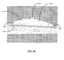
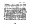
- the signal processor 118 generates an overlay image that includes any obstacles detected by the forward looking radar 135. This obstacle overlay image is to be added to a terrain image in order to display information about any obstacles that are ahead of the aerial vehicle.
- An image corresponding to a set of obstacles (which might include no obstacles, or one or more obstacles) ahead of the aerial vehicle (that is, the obstacle overlay image) is superimposed on an image corresponding to terrain data near which the aerial vehicle is located (that is, the terrain image) in order to generate a composite image. At least a portion of the composite image is displayed on one or more display devices so that respective portions of both the terrain image and obstacle image are both displayed together on the same one or more display devices.
- the radar data processing engine generates the obstacle overlay image. In other words, the radar processing engine 126 performs the image formation and processing, such as determining the position of the aerial vehicle, and generating the obstacle overlay image.
- the software 122 executed by the signal processor 118 provides an altitude display 175 with altitude data.
- the altitude display 175 can be any display device operable to display altitude data, for example a digital display, a LCD monitor, an LED display, or the like.
- the altitude data is displayed on the display device 176 by superimposing it upon the composite image.
- the enhanced vision system 100 includes a GPS receiver 130.
- the GPS receiver 130 determines the position of the aerial vehicle when GPS is available. In GPS denied conditions, the GPS receiver 130 is unable to provide the position of the aerial vehicle, so other means of determining the precise location of the aerial vehicle are utilized. In other embodiments, the enhanced vision system 100 does not include a GPS receiver 130.
- the enhanced vision system 100 further comprises an inertial measurement unit (IMU) 140.
- the IMU 140 provides attitude data for the aerial vehicle (that is, the IMU 140 senses the orientation of the aerial vehicle with respect to the terrain).
- the IMU 140 includes accelerometers for sensing a linear change in rate (that is, acceleration) along a given axis and gyroscopes for sensing change in angular rate (that is, used to determine rotational velocity or angular position).
- the IMU 140 determines the aerial vehicle's attitude and blends GPS position and PTAN position data.
- the IMU 140 provides position information at a uniform rate to the terrain rendering engine 124 implemented by the signal processor 118 so that the rendered images of the terrain data and the radar data move smoothly on the display device 176.
- the blending of the two position data sources provides a smooth transition between GPS available and GPS denied conditions.
- a smooth transition is accomplished by running both systems (that is, GPS and PTAN) simultaneously, calculating the position difference between them, and estimating the true position based on the dilution of precision calculated for each system at any given time. This establishes a position offset for each system.
- GPS or the PTAN system is no longer available, the offset between the estimated position and the position as calculated by the available system is added to the position of the available system in order to prevent a jump in apparent position of the aerial vehicle.
- the offset diminishes with time as long as only one system is available, as there is no secondary reference to indicate a different position as the correct position.
- the terrain database 152 stores detailed maps of the earth's surface comprising terrain data (also referred to herein as map data), which includes elevation information.
- the maps stored in the terrain database 152 can include a global mapping of the earth.
- the terrain data in the database 152 is referenced to an earth coordinate system. Flight data from the radar altimeter 110, the forward looking radar 135, and the IMU 140 are geo-referenced by transforming the data into the earth coordinate system used by the terrain database 152. Using a single coordinate system enables an image rendering engine 164 to easily match the detected obstacles from the obstacle overlay image data with terrain data from the terrain database 152.
- the terrain database 152 is stored in or on one or more storage devices or media 150.
- the signal processor 118 reads the terrain data from the one or more storage devices or media 150.
- Suitable storage devices or media 150 include, for example, forms of non-volatile memory, including by way of example, semiconductor memory devices (such as EPROM, EEPROM, and flash memory devices), magnetic disks (such as local hard disks and removable disks), and optical disks (such as CD-ROM disks).
- the storage device or media 150 need not be local to the system 100.
- the terrain database 152 provides terrain data to the signal processor 118.
- the terrain rendering engine 124 correlates the terrain features within the elevation track data from the PTAN radar 114. Correlating the elevation track data with the map data enables the system 100 to determine the precise position of the aerial vehicle in GPS denied conditions.
- the terrain database 152 is a stored Digital Terrain Elevation Database (DTED) that is available from Honeywell International, Inc. (hereinafter referred to as Honeywell) or from the United States government.
- the DTED can be used to provide precision positions of the aerial vehicle equal to or better than GPS, allowing for high accuracy positioning within GPS denied environments.
- the DTED level 4 database has a resolution of 3 meters. However, the accuracy of the database and resolution is dependent on the source.
- the system 100 also includes an Integrated Primary Flight Display (IPDF) 160.
- the IPDF 160 is a synthetic vision system (SVS) which offers high resolution imaging of the surrounding terrain and obstacles near the aerial vehicle.
- SVS synthetic vision system
- the IPDF 160 comprises a flight computer 162 and a display device 176.
- the flight computer 162 is used to implement the image rendering engine 164.
- the image rendering engine 164 is implemented in software 168 that is executed by a suitable processor 172.
- the software 168 comprises program instructions that are stored on a suitable storage device or medium 166.
- Suitable storage devices or media 166 include, for example, forms of non-volatile memory, including by way of example, semiconductor memory devices (such as EPROM, EEPROM, and flash memory devices), magnetic disks (such as local hard disks and removable disks), and optical disks (such as CD-ROM disks). Moreover, the storage device or media 166 need not be local to the system 100. Typically, a portion of the software 168 executed by the processor 172 and one or more data structures used by the software 168 during execution are stored in a memory 170. Memory 170 comprises, in one implementation of such an embodiment, any suitable form of random access memory (RAM) now known or later developed, such as dynamic random access memory (DRAM). In other embodiments, other types of memory are used.
- RAM random access memory
- DRAM dynamic random access memory
- the components of flight computer 162 are communicatively coupled to one another as needed using suitable interfaces and interconnects.
- the image rendering engine 164 overlays the obstacle overlay image onto the terrain image.
- the IPFD 160 and PTAN radar altimeter 110 share a common DTED 60 Gb database hard drive (not shown).
- the display device 176 displays the composite image of the terrain image and the obstacle image overlay to a user (such as a pilot).
- the composite image is a superposition of the obstacle image data onto the terrain image.
- the display device 176 is operable to display additional information as well, such as object tracking information, altitude, pitch, pressure, and the like.
- the display device 176 can be any device or group of devices for presenting visual information, such as a liquid crystal display (LCD), plasma monitor, cathode ray tube (CRT), or the like.
- the display device 176 is a single LCD that presents the composite image to a user.
- the display device 176 is multiple LCDs that are used to present the composite image to a user (in other words, each individual LCD displays some portion of the object image overlay superimposed on the terrain image).
- the signal processor 118 provides the radar image and obstacle image overlay to an image rendering engine 164.
- Other information provided to the image rendering engine 164 includes attitude data transmitted from the IMU 140 and map data from the terrain database 152. If GPS connection is available, position data from the GPS receiver 130 is provided to the image rendering engine 164.
- Figure 1 shows the image rendering engine 164 as being implemented separately from the PTAN radar altimeter 110, although in other embodiments and implementations the image rendering engine 164 can be implemented within the PTAN radar altimeter 110.
- the image rendering engine 164 overlays the obstacle overlay image onto the terrain map and generates perspectives for the composite image. Using the attitude data from the IMU 140, the image rendering engine 164 tilts the image to correct for movements of the aerial vehicle.
- the composite image is provided to the display device 176, which in one embodiment is a synthetic image display.
- the display device 176 displays the composite image to a pilot, and corrections for tilt of the aerial vehicle are made real-time.
- the display 176 is implemented using the Common Avionics Architecture System (CAAS) flight display system that is commercially available from Honeywell.
- CAAS Common Avionics Architecture System
- the obstacle data and the altitude data from the PTAN radar altimeter 110 is sent to a data recorder 180.
- the data recorder 180 records the flight information and stores it in a computer readable memory 182.
- the flight information can be provided to the data recorder 180 from the PTAN radar altimeter 110 over optical cable, or by any other method of transmission.
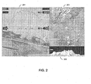
- Figure 2 is an image of one embodiment of the perspectives displayable in a synthetic vision system (SVS).
- SVS employs computer generated terrain imagery from onboard DTED databases matched with precision navigation information to create a presentation of the outside world around the aerial vehicle.
- the IPFD provides a clear electronic representation of the outside world around the aerial vehicle, and can display different perspectives.
- the image shown at 201 is a three-dimensional (3D) perspective (egocentric) view, with flight data superimposed on the composite image (such as altitude, pitch, tilt, etc.).
- the image 203 depicts a plan view (lookdown, exocentric), and the image 205 displays a vertical profile.
- the SVS can include additional features to aid flight, such as displaying other sensor information (attitude, elevation, etc.).
- This synthetic vision system integrates together primary flight information from all available sources on the aerial vehicle (such as the radar and IMU sensors).
- the IPFD synthetic vision system can also functionally host the Military Digital Moving Map (DMM) by Honeywell, which is a display system that shows the geographic area an aerial vehicle is in, updated as the aerial vehicle moves.
- MDM Military Digital Moving Map
- the enhanced vision system (EVS) described above in connection with Figure 1 provides real time imaging by merging sensor data with the IPFD 160. SVS and EVS data merged on the IPFD 160 shows "what is actually out there" to provide greater situational and obstacle awareness.
- the raw sensor return is processed by the image rendering engine 164 to clean up the image and geospatially scale and align the image to the IPFD 160, which offers a greater field of view and cleaner imaging than sensor imaging alone.
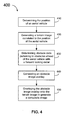
- a terrain image correlated to the position of the aerial vehicle is generated (block 420).
- the terrain image is generated by a terrain rendering engine 118.
- the terrain rendering engine 118 takes the position data, either from GPS 130 or the PTAN radar altimeter 110, along with attitude information and renders an image of the terrain.
- the terrain image can be provided by a digital map data stored in a memory onboard the aerial vehicle.
- One such digital map database is the Digital Terrain Elevation Database (DTED) that is commercially available from Honeywell.
- the position of the aerial vehicle determines the corresponding coordinates of the digital map.
- the IMU 140 provides attitude data pertaining to the attitude of the aerial vehicle, which can be used to orient the map.
- the map can be oriented such that the terrain ahead of the aerial vehicle would be shown in a display device 176.
- the method 400 further comprises determining obstacle data pertaining to obstacles ahead of the aerial vehicle (block 430). Obstacles ahead of the aerial vehicle are detected by a forward looking radar 135 or other sensor (such as a FLIR). In one implementation of this embodiment, the forward looking radar 135 operates at approximately 94 GHz. Additionally, the method 400 can be implemented using many types of sensors including advanced Millimeter Wave Radar, Laser Detection and Ranging (LADAR), and optical cooled and uncooled infrared systems.
- LADAR Laser Detection and Ranging
- an obstacle overlay image is generated (block 440).
- the obstacle overlay image is information to be added to a terrain display indicating obstacles present ahead of the aerial vehicle. Such obstacles include cables, poles for running cables, buildings, and the like.
- the radar data processing engine 118 generates the obstacle overlay image.
- the obstacle overlay image is overlain onto the terrain image to generate a composite image (block 450).
- the image rendering engine 164 takes the range and bearing information from the forward looking radar generated by the radar data processing engine 118 and overlays this radar return object data onto the terrain image to generate a composite image showing real-time updated terrain obstacles such as cables and other small objects that are not present in the terrain elevation map data.
- this composite image shows the terrain ahead of the aerial vehicle with images of the obstacles detected by the forward looking radar 135 superimposed on the terrain image.
- the composite image is presented to a pilot on a display device and is updated in real-time.
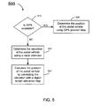
- Figure 5 is a flowchart of one embodiment of a method 500 of determining the position of an aerial vehicle.
- the embodiment of method 500 shown in Figure 5 is described here as being implemented using the EVS 100 of Figure 1 and 2 , though other embodiments are implemented in other ways.
- the aerial vehicle is equipped with a GPS receiver 130.
- Method 500 comprises querying whether GPS is available (block 510). If GPS is available, the position of the aerial vehicle is determined from the GPS position data (block 520).
- the altitude of the aerial vehicle is determined (block 530).
- the altitude of the aerial vehicle can be determined by using a radar altimeter or by any other method known to those of skill in the art.
- One contemplated radar altimeter is the Precision Terrain Aided Navigation (PTAN) radar altimeter that is commercially available from Honeywell.
- PTAN Precision Terrain Aided Navigation
- the position of the aerial vehicle is calculated by correlating the altitude with a digital terrain map (block 540). A single altitude value is insufficient to indicate where the aerial vehicle is located, but a track of altitudes gathered over the course of flight can be used to match to the digital elevation map 152.
- the PTAN radar altimeter 110 is used to determine position with GPS-like accuracy without the use of GPS by comparing ground track radar altitude measurements to the stored digital elevation map data 152.
- Data from the IMU 140 can also be used in determining the position of the aerial vehicle.
- the correlation of the altitude data with the digital terrain map 152 can be narrowed using previous known positions of the aerial vehicle, its trajectory, and inertial data from the IMU 140.
- the IMU data can be used to orient the map to the direction of travel of the aerial vehicle, in GPS allowed or GPS denied conditions.
- Attitude data from the IMU 140 can be correlated with the altitude of the aerial vehicle.
- the IMU data is used to smooth the transition between GPS allowed and GPS denied conditions.
- embodiments provide precision navigation solutions for aerial vehicle without the use of Global Positioning Satellite (GPS) inputs which maximize each of the navigation's s separate systems' features to provide a combined accuracy beyond the aerial vehicle's current navigational system's capabilities.
- GPS Global Positioning Satellite
- the EVS with PTAN and an Integrated Primary Flight Display provides a highly accurate autonomous navigation solution in GPS denied conditions.
- the EVS 100 of Figure 1 provides the best of all onboard sensors by combining independent sensor instruments such as a FLIR or a 94 GHz millimeter wave radar system into a large high resolution image with IPFD 160.
- the enhanced vision system 100 provides a forward looking radar 135 capable of detecting cables and ground objects in low visibility conditions along with a method of determining position alternative to GPS.
- the accuracy of the position can be increased by the PTAN system 110.
- Data from the forward-looking radar sensor 135 on the aerial vehicle can be overlaid onto the terrain image and displayed to the pilots. The combination of these systems increases the accuracy of the current onboard inertial navigation system and the aerial vehicle's current flight display system, as well as increased operational capability in limited visibility scenarios.
- the EVS 100 with PTAN 110 is an onboard system that can provide terrain situational awareness and the aerial vehicle's positional data while reducing emissions from the aerial vehicle and reliance on GPS and IMU data.
Landscapes
- Engineering & Computer Science (AREA)
- Radar, Positioning & Navigation (AREA)
- Remote Sensing (AREA)
- Physics & Mathematics (AREA)
- General Physics & Mathematics (AREA)
- Aviation & Aerospace Engineering (AREA)
- Computer Networks & Wireless Communication (AREA)
- Electromagnetism (AREA)
- Navigation (AREA)
- Traffic Control Systems (AREA)
Claims (7)
- Verfahren zum Erzeugen eines Bildes eines Volumens vor einem Luftfahrzeug (410), wobei das Verfahren Folgendes umfasst:Bestimmen einer Position des Luftfahrzeugs (410) unter Verwendung von Daten eines globalen Positionierungssystems (130), wenn Daten eines globalen Positionierungssystems verfügbar sind, und wenn Daten eines globalen Positionierungssystems nicht verfügbar sind, Bestimmen der Position des Luftfahrzeugs durch:Bestimmen einer Höhe des Luftfahrzeugs (410) unter Verwendung eines Radarhöhenmessgeräts (110); undBerechnen der Position des Luftfahrzeugs (410) durch Korrelieren der Höhe mit einer digitalen Geländehöhenkarte (152) und Korrelieren der Höhendaten des Luftfahrzeugs von einem Inertialnavigationssystem (140) mit der Höhe des Luftfahrzeugs (410);Erzeugen eines Geländebildes (201), das den Bodenmerkmalen (302, 304, 306, 310, 312) entspricht, die mit der Position des Luftfahrzeugs (420) korreliert sind;Bestimmen von Hindernisdaten, die eine Gruppe von Hindernissen vor dem Luftfahrzeug betreffen, mit einem nach vorne gerichteten Sensor (430);Erzeugen eines Hindernisüberlagerungsbildes (440); undÜberlagern des Hindernisüberlagerungsbildes mit dem Geländebild, um ein zusammengesetztes Bild (450) zu erzeugen;dadurch gekennzeichnet, dass das Inertialnavigationssystem (140) betreibbar ist, einen Übergang zwischen dem Zeitpunkt, zu dem Daten eines globalen Positionierungssystems verfügbar sind, und dem Zeitpunkt, zu dem Daten eines globalen Positionierungssystems nicht verfügbar sind, zu glätten durch:Bestimmen eines Positionsunterschieds zwischen den Daten eines globalen Positionierungssystems und den Positionsdaten, die durch Korrelieren der Höhe mit der digitalen Geländekarte (152) berechnet wurden;Erstellen eines Offsets für die Daten eines globalen Positionierungssystems und eines Offsets für die Positionsdaten, die durch Korrelieren der Höhe mit der digitalen Geländehöhenkarte (152) berechnet wurden, anhand des Positionsunterschieds;Addieren des Offsets für die Daten eines globalen Positionierungssystems zu den Positionsdaten, die durch Korrelieren der Höhe mit der digitalen Geländehöhenkarte (152) berechnet wurden, wenn Daten eines globalen Positionierungssystems nicht verfügbar sind; undVerringern des Offsets für die Daten eines globalen Positionierungssystems mit der Zeit, solange die Daten des globalen Positionierungssystems nicht verfügbar sind.
- Verfahren nach Anspruch 1, wobei das Luftfahrzeug mindestens einen Teil eines zusammengesetzten Bildes auf mindestens einer Anzeigevorrichtung (176) anzeigt.
- Verfahren nach Anspruch 1, das ferner umfasst, eine Signalverarbeitungseinheit (118) zwischen dem Bestimmen der Position des Luftfahrzeugs (410) und Erzeugen der Hindernisdatenbildüberlagerung zeitlich zu teilen.
- Verfahren nach Anspruch 1, wobei ein nach vorne gerichteter Sensor (135), der an das Radarhöhenmessgerät (110) gekoppelt ist, mindestens ein nach vorne gerichtetes 94 GHz-Radar, einen nach vorne gerichteten Infrarotsensor (FLIR-Sensor), einen Laserdetektions- und Entfernungsmessungs-Sensor (LADAR-Sensor) und ein Millimeterwellenradar (MMW) umfasst.
- Verbessertes Sichtsystem für ein Luftfahrzeug (410), wobei das System Folgendes umfasst:ein Radarhöhenmessgerät (110), das betreibbar ist, Höhendaten, die eine Höhe des Luftfahrzeugs (410) betreffen, zu erzeugen;ein nach vorne gerichtetes Radar (135), das betreibbar ist, Hindernisdaten (302-B, 304-B, 306-B, 310-B, 312-B), die eine Gruppe von Hindernissen vor dem Luftfahrzeug (302-A, 304-A, 306-A, 310-A, 312-A) betreffen, zu erzeugen; undein Inertialnavigationssystem (IMU) (140), das betreibbar ist, Höhendaten, die eine Höhe des Luftfahrzeugs betreffen, zu bestimmen; undeinen Empfänger eines globalen Positionierungssystems (130), der betreibbar ist, Daten des globalen Positionierungssystems für die Verwendung durch das verbesserte Sichtsystem im Rendern eines Geländebildes zu liefern;wobei das System betreibbar ist,
Positionsdaten durch Korrelieren der Höhendaten mit einer digitalen Geländehöhenkarte (540) zu berechnen;
ein Hindernisüberlagerungsbild (440) zu erzeugen;
ein Geländebild unter Verwendung der Positionsdaten und der Höhendaten (420) wiederzugeben;
das Hindernisdatenüberlagerungsbild mit dem Geländebild zu überlagern, um ein zusammengesetztes Bild (450) zu erzeugen; undwobei das System ferner eine Anzeige (176) umfasst, auf der das zusammengesetzte Bild angezeigt wird;dadurch gekennzeichnet, dass das Inertialnavigationssystem (140) betreibbar ist, einen Übergang zwischen dann, wenn Daten eines globalen Positionierungssystems verfügbar sind, und dann, wenn Daten eines globalen Positionierungssystems nicht verfügbar sind, zu glätten durch:Bestimmen eines Positionsunterschieds zwischen den Daten des globalen Positionierungssystems und den Positionsdaten, die durch Korrelieren der Höhe mit der digitalen Geländekarte (152) berechnet wurden;Erstellen eines Offsets für die Daten eines globalen Positionierungssystems und eines Offsets für die Positionsdaten, die durch Korrelieren der Höhe mit der digitalen Geländehöhenkarte (152) berechnet wurden, anhand des Positionsunterschieds;Addieren des Offsets für die Daten eines globalen Positionierungssystems zu den Positionsdaten, die durch Korrelieren der Höhe mit der digitalen Geländehöhenkarte (152) berechnet wurden, wenn Daten eines globalen Positionierungssystems nicht verfügbar sind; undVerringern des Offsets für die Daten eines globalen Positionierungssystems mit der Zeit, solange die Daten des globalen Positionierungssystems nicht verfügbar sind. - Verbessertes Sichtsystem nach Anspruch 5, wobei das nach vorne gerichtete Radar (135) bei ungefähr 94 GHz arbeitet.
- Verbessertes Sichtsystem nach Anspruch 5, wobei das Radarhöhenmessgerät (110) eine Signalverarbeitungseinheit (118) umfasst, die zwischen dem Berechnen der Positionsdaten und Erzeugen der Hindernisdatenbildüberlagerung zeitlich geteilt wird.
Applications Claiming Priority (1)
| Application Number | Priority Date | Filing Date | Title |
|---|---|---|---|
| US12/426,892 US8296056B2 (en) | 2009-04-20 | 2009-04-20 | Enhanced vision system for precision navigation in low visibility or global positioning system (GPS) denied conditions |
Publications (3)
| Publication Number | Publication Date |
|---|---|
| EP2244239A2 EP2244239A2 (de) | 2010-10-27 |
| EP2244239A3 EP2244239A3 (de) | 2011-11-02 |
| EP2244239B1 true EP2244239B1 (de) | 2013-08-28 |
Family
ID=42289761
Family Applications (1)
| Application Number | Title | Priority Date | Filing Date |
|---|---|---|---|
| EP10159282.2A Active EP2244239B1 (de) | 2009-04-20 | 2010-04-07 | Verbessertes Sichtsystem zur Präzisionsnavigation bei geringer Sicht oder unter Umständen der Unmöglichkeit von GPS |
Country Status (2)
| Country | Link |
|---|---|
| US (1) | US8296056B2 (de) |
| EP (1) | EP2244239B1 (de) |
Cited By (1)
| Publication number | Priority date | Publication date | Assignee | Title |
|---|---|---|---|---|
| US11698461B1 (en) | 2019-11-20 | 2023-07-11 | Telephonics Corp. | GPS denial detection and reporting and mitigation |
Families Citing this family (52)
| Publication number | Priority date | Publication date | Assignee | Title |
|---|---|---|---|---|
| US8942483B2 (en) | 2009-09-14 | 2015-01-27 | Trimble Navigation Limited | Image-based georeferencing |
| US8897541B2 (en) | 2009-09-14 | 2014-11-25 | Trimble Navigation Limited | Accurate digitization of a georeferenced image |
| US8717430B2 (en) * | 2010-04-26 | 2014-05-06 | Medtronic Navigation, Inc. | System and method for radio-frequency imaging, registration, and localization |
| JP2011247860A (ja) * | 2010-05-31 | 2011-12-08 | Denso Corp | ナビゲーション装置 |
| US8855937B2 (en) | 2010-10-25 | 2014-10-07 | Trimble Navigation Limited | Crop characteristic estimation |
| US9408342B2 (en) | 2010-10-25 | 2016-08-09 | Trimble Navigation Limited | Crop treatment compatibility |
| US9213905B2 (en) * | 2010-10-25 | 2015-12-15 | Trimble Navigation Limited | Automatic obstacle location mapping |
| US9058633B2 (en) | 2010-10-25 | 2015-06-16 | Trimble Navigation Limited | Wide-area agricultural monitoring and prediction |
| US10115158B2 (en) | 2010-10-25 | 2018-10-30 | Trimble Inc. | Generating a crop recommendation |
| US9846848B2 (en) | 2010-10-25 | 2017-12-19 | Trimble Inc. | Exchanging water allocation credits |
| US8493241B2 (en) * | 2010-11-30 | 2013-07-23 | Honeywell International Inc. | Systems, methods and computer readable media for displaying multiple overlaid images to a pilot of an aircraft during flight |
| US9092975B2 (en) * | 2011-02-23 | 2015-07-28 | Honeywell International Inc. | Aircraft systems and methods for displaying visual segment information |
| US8868323B2 (en) | 2011-03-22 | 2014-10-21 | Honeywell International Inc. | Collaborative navigation using conditional updates |
| US8660338B2 (en) * | 2011-03-22 | 2014-02-25 | Honeywell International Inc. | Wide baseline feature matching using collobrative navigation and digital terrain elevation data constraints |
| US8457882B2 (en) | 2011-04-19 | 2013-06-04 | Honeywell International Inc. | Systems and methods for navigation in a GPS-denied environment |
| US8812225B2 (en) | 2011-04-29 | 2014-08-19 | Harris Corporation | Electronic navigation device for a human and related methods |
| US8411113B1 (en) * | 2011-10-12 | 2013-04-02 | Google Inc. | Layered digital image data reordering and related digital image rendering engine |
| US9347792B2 (en) | 2011-10-31 | 2016-05-24 | Honeywell International Inc. | Systems and methods for displaying images with multi-resolution integration |
| US8744763B2 (en) | 2011-11-17 | 2014-06-03 | Honeywell International Inc. | Using structured light to update inertial navigation systems |
| US8698654B2 (en) | 2011-12-28 | 2014-04-15 | Honeywell International Inc. | System and method for selecting images to be displayed |
| US9347793B2 (en) * | 2012-04-02 | 2016-05-24 | Honeywell International Inc. | Synthetic vision systems and methods for displaying detached objects |
| US8766975B2 (en) * | 2012-07-19 | 2014-07-01 | Honeywell International Inc. | Method of correlating images with terrain elevation maps for navigation |
| US9390559B2 (en) | 2013-03-12 | 2016-07-12 | Honeywell International Inc. | Aircraft flight deck displays and systems and methods for enhanced display of obstacles in a combined vision display |
| US20140285661A1 (en) * | 2013-03-22 | 2014-09-25 | Honeywell International Inc | Methods and systems for colorizing an enhanced image during alert |
| US9139307B2 (en) | 2013-06-28 | 2015-09-22 | Honeywell International Inc. | Aircraft systems and methods for displaying runway lighting information |
| US20150019048A1 (en) * | 2013-07-15 | 2015-01-15 | Honeywell International Inc. | Display systems and methods for providing displays having an adaptive combined vision system |
| GB2523097B (en) * | 2014-02-12 | 2016-09-28 | Jaguar Land Rover Ltd | Vehicle terrain profiling system with image enhancement |
| WO2015148604A1 (en) | 2014-03-25 | 2015-10-01 | Massachusetts Institute Of Technology | Space-time modulated active 3d imager |
| US10089766B2 (en) * | 2014-03-28 | 2018-10-02 | Konica Minolta Laboratory U.S.A., Inc | Method and system of stitching aerial data using information from previous aerial images |
| NO340705B1 (no) * | 2014-12-22 | 2017-06-06 | Kleon Prosjekt As | Fremgangsmåte og innretning for å detektere et luftspenn fra et luftfartøy |
| TR201809643T4 (tr) * | 2015-01-14 | 2018-07-23 | Stm Savunma Teknolojileri Muehendislik Ve Ticaret Anonim Sirketi | Hassas konum belirleme yöntemi. |
| IL239148A0 (en) * | 2015-06-02 | 2015-11-30 | Elbit Systems Ltd | A method and system for calculating and presenting areas that can be reached while maintaining space-space |
| WO2017160381A1 (en) * | 2016-03-16 | 2017-09-21 | Adcor Magnet Systems, Llc | System for georeferenced, geo-oriented real time video streams |
| US10394240B1 (en) * | 2016-05-06 | 2019-08-27 | Olaeris, Inc. | Failover navigation for remotely operated aerial vehicles |
| US10422872B2 (en) * | 2016-06-01 | 2019-09-24 | Honeywell International Inc. | Integrity monitoring of radar altimeters |
| WO2018009109A1 (en) * | 2016-07-07 | 2018-01-11 | Saab Ab | Displaying system and method for displaying a perspective view of the surrounding of an aircraft in an aircraft |
| FR3061598B1 (fr) * | 2016-12-29 | 2020-10-16 | Thales Sa | Procede de calcul et d'affichage d'informations de pilotage comportant un " relief factor" |
| US10371812B2 (en) * | 2017-02-23 | 2019-08-06 | Rosemount Aerospace Inc. | Ultra-wideband radar altimeter |
| US10599959B2 (en) * | 2017-04-05 | 2020-03-24 | International Business Machines Corporation | Automatic pest monitoring by cognitive image recognition with two cameras on autonomous vehicles |
| US20180373269A1 (en) * | 2017-06-26 | 2018-12-27 | Walmart Apollo, Llc | Systems and methods using a backup navigational tool for unmanned aerial vehicles delivering merchandise |
| EP3517996B1 (de) * | 2018-01-25 | 2022-09-07 | Aptiv Technologies Limited | Verfahren zur bestimmung der position eines fahrzeugs |
| CN109658500B (zh) * | 2018-12-11 | 2023-01-13 | 中国航空工业集团公司西安航空计算技术研究所 | 一种基于毫米波雷达的直升机合成视景方法、系统及存储介质 |
| US11105921B2 (en) * | 2019-02-19 | 2021-08-31 | Honeywell International Inc. | Systems and methods for vehicle navigation |
| US11378986B2 (en) * | 2019-04-01 | 2022-07-05 | Honeywell International Inc. | Systems and methods for landing and takeoff guidance |
| CN112556700A (zh) * | 2019-09-25 | 2021-03-26 | 华为技术有限公司 | 地图级别指示方法、地图级别获取方法及相关产品 |
| EP3951322B1 (de) * | 2020-08-04 | 2023-08-30 | Honeywell International Inc. | Systeme und verfahren zur kalibrierung einer sensorposition auf einem flugzeug |
| US11408751B2 (en) | 2020-08-04 | 2022-08-09 | Honeywell International Inc. | Systems and methods for calibrating a sensor position on an aircraft |
| US11914053B2 (en) | 2021-01-11 | 2024-02-27 | Honeywell International Inc. | Vehicle location accuracy enhancement system |
| US12078738B2 (en) | 2021-11-09 | 2024-09-03 | Msrs Llc | Method, apparatus, and computer readable medium for a multi-source reckoning system |
| US20230316931A1 (en) * | 2022-04-05 | 2023-10-05 | Michael Ryan | Positioning alert system for aircraft |
| FR3150627B1 (fr) * | 2023-06-28 | 2025-10-03 | Faurecia Clarion Electronics Europe | Procédé d’affichage |
| US12259246B1 (en) | 2024-05-13 | 2025-03-25 | Msrs Llc | Method, apparatus, and computer readable medium for calculating a handrail influence intensity factor |
Family Cites Families (17)
| Publication number | Priority date | Publication date | Assignee | Title |
|---|---|---|---|---|
| DE69606804T2 (de) | 1995-06-20 | 2000-06-15 | Honeywell, Inc. | Integriertes System zur Grundkollisionsvermeidung |
| US6606034B1 (en) | 1995-07-31 | 2003-08-12 | Honeywell International Inc. | Terrain awareness system |
| US5839080B1 (en) | 1995-07-31 | 2000-10-17 | Allied Signal Inc | Terrain awareness system |
| US5828332A (en) | 1996-03-11 | 1998-10-27 | Imaging Accessories, Inc. | Automatic horizontal and vertical scanning radar with terrain display |
| US6216065B1 (en) | 1999-08-06 | 2001-04-10 | Bell Helicopter Textron Inc. | Method and system for creating an approach to a position on the ground from a location above the ground |
| WO2001046766A1 (en) * | 1999-12-21 | 2001-06-28 | Lockheed Martin Corporation | Spatial avoidance method and apparatus |
| US6362776B1 (en) | 2000-02-04 | 2002-03-26 | Honeywell International Inc. | Precision radar altimeter with terrain feature coordinate location capability |
| US6512976B1 (en) | 2001-04-27 | 2003-01-28 | Honeywell International Inc. | Method and system for terrain aided navigation |
| US6873269B2 (en) * | 2003-05-27 | 2005-03-29 | Honeywell International Inc. | Embedded free flight obstacle avoidance system |
| US6897803B2 (en) | 2003-06-11 | 2005-05-24 | Honeywell International Inc. | Radar altimeter with forward ranging capabilities |
| US6750807B1 (en) | 2003-06-11 | 2004-06-15 | Honeywell International Inc. | Radar altimeter with forward obstacle avoidance capabilities |
| US6885334B1 (en) | 2004-04-06 | 2005-04-26 | Honeywell International Inc. | Methods and systems for detecting forward obstacles |
| US7409293B2 (en) | 2004-06-03 | 2008-08-05 | Honeywell International Inc. | Methods and systems for enhancing accuracy of terrain aided navigation systems |
| US7269513B2 (en) | 2005-05-03 | 2007-09-11 | Herwitz Stanley R | Ground-based sense-and-avoid display system (SAVDS) for unmanned aerial vehicles |
| US7486221B2 (en) | 2005-11-18 | 2009-02-03 | Honeywell International Inc. | Methods and systems for using pulsed radar for communications transparent to radar function |
| US7409292B2 (en) | 2006-05-26 | 2008-08-05 | Honeywell International Inc. | Method and system for degimbalization of vehicle navigation data |
| US7489268B2 (en) | 2007-01-08 | 2009-02-10 | Honeywell International Inc. | Methods and systems for producing an interpretive airborne radar map |
-
2009
- 2009-04-20 US US12/426,892 patent/US8296056B2/en active Active
-
2010
- 2010-04-07 EP EP10159282.2A patent/EP2244239B1/de active Active
Cited By (1)
| Publication number | Priority date | Publication date | Assignee | Title |
|---|---|---|---|---|
| US11698461B1 (en) | 2019-11-20 | 2023-07-11 | Telephonics Corp. | GPS denial detection and reporting and mitigation |
Also Published As
| Publication number | Publication date |
|---|---|
| EP2244239A2 (de) | 2010-10-27 |
| US20100268458A1 (en) | 2010-10-21 |
| US8296056B2 (en) | 2012-10-23 |
| EP2244239A3 (de) | 2011-11-02 |
Similar Documents
| Publication | Publication Date | Title |
|---|---|---|
| EP2244239B1 (de) | Verbessertes Sichtsystem zur Präzisionsnavigation bei geringer Sicht oder unter Umständen der Unmöglichkeit von GPS | |
| US7352292B2 (en) | Real-time, three-dimensional synthetic vision display of sensor-validated terrain data | |
| US7215256B2 (en) | Method and apparatus for displaying attitude, heading, and terrain data | |
| EP2587222B1 (de) | System zum Anzeigen von Bildern mit Integration von mehreren Auflösungen | |
| EP1897081B1 (de) | Verkehrshindernisanzeige in konformer perspektivansicht | |
| US9384586B1 (en) | Enhanced flight vision system and method with radar sensing and pilot monitoring display | |
| EP3073225B1 (de) | Synthetische flugzeugsichtsysteme unter verwendung von daten aus local-area-augmentation-systemen sowie verfahren zum betrieb solcher synthetischer flugzeugsichtsysteme | |
| EP2228626B1 (de) | Verfahren und System zur Korrelation von Datenquellen für Bordfahrzeuganzeigevorrichtungen | |
| US6219594B1 (en) | Landing area obstacle detection radar system | |
| EP2267409B1 (de) | System und Verfahren zur Anzeige von Informationen auf einem Anzeigeelement | |
| EP3029419B1 (de) | System und verfahren zur unterstützung eines piloten beim auffinden eines landeplatzes ausserhalb des sichtbereichs | |
| EP2782086A1 (de) | Verfahren und Systeme zum Färben eines vergrößerten Bildes während eines Alarms | |
| EP2204639A1 (de) | Systeme und Verfahren zur Verbesserung des Geländeanhebungsbewusstseins | |
| EP2169355B1 (de) | Systeme und Verfahren zur Anzeige von Bildern mit Geländedaten | |
| US20080198157A1 (en) | Target zone display system and method | |
| EP2613125B1 (de) | System und Verfahren zum Anzeigen eines perspektivischen Sichtfeldes auf einer Anzeige zur vertikalen Situation | |
| EP2037216B1 (de) | System und Verfahren zum Anzeigen eines digitalen Geländes | |
| WO2020261255A1 (en) | Geolocation of head-mounted image sensor using celestial navigation | |
| RU2234739C1 (ru) | Способ предотвращения столкновения летательного аппарата с землей | |
| US20160362190A1 (en) | Synthetic vision | |
| EP4000982B1 (de) | Systeme und verfahren zur visualisierung von erweiterter realität basierend auf sensordaten | |
| Gallo | Obstacle detection and warning system for aircraft navigation at airports |
Legal Events
| Date | Code | Title | Description |
|---|---|---|---|
| PUAI | Public reference made under article 153(3) epc to a published international application that has entered the european phase |
Free format text: ORIGINAL CODE: 0009012 |
|
| 17P | Request for examination filed |
Effective date: 20100407 |
|
| AK | Designated contracting states |
Kind code of ref document: A2 Designated state(s): AT BE BG CH CY CZ DE DK EE ES FI FR GB GR HR HU IE IS IT LI LT LU LV MC MK MT NL NO PL PT RO SE SI SK SM TR |
|
| AX | Request for extension of the european patent |
Extension state: AL BA ME RS |
|
| PUAL | Search report despatched |
Free format text: ORIGINAL CODE: 0009013 |
|
| AK | Designated contracting states |
Kind code of ref document: A3 Designated state(s): AT BE BG CH CY CZ DE DK EE ES FI FR GB GR HR HU IE IS IT LI LT LU LV MC MK MT NL NO PL PT RO SE SI SK SM TR |
|
| AX | Request for extension of the european patent |
Extension state: AL BA ME RS |
|
| RIC1 | Information provided on ipc code assigned before grant |
Ipc: G01S 13/94 20060101ALN20110927BHEP Ipc: G08G 5/00 20060101AFI20110927BHEP |
|
| 17Q | First examination report despatched |
Effective date: 20111102 |
|
| GRAP | Despatch of communication of intention to grant a patent |
Free format text: ORIGINAL CODE: EPIDOSNIGR1 |
|
| RIC1 | Information provided on ipc code assigned before grant |
Ipc: G08G 5/00 20060101AFI20130426BHEP Ipc: G01S 13/93 20060101ALN20130426BHEP Ipc: G01S 7/22 20060101ALI20130426BHEP Ipc: G01C 23/00 20060101ALI20130426BHEP Ipc: G01S 13/94 20060101ALN20130426BHEP Ipc: G01S 13/86 20060101ALN20130426BHEP |
|
| INTG | Intention to grant announced |
Effective date: 20130516 |
|
| GRAS | Grant fee paid |
Free format text: ORIGINAL CODE: EPIDOSNIGR3 |
|
| GRAA | (expected) grant |
Free format text: ORIGINAL CODE: 0009210 |
|
| AK | Designated contracting states |
Kind code of ref document: B1 Designated state(s): AT BE BG CH CY CZ DE DK EE ES FI FR GB GR HR HU IE IS IT LI LT LU LV MC MK MT NL NO PL PT RO SE SI SK SM TR |
|
| REG | Reference to a national code |
Ref country code: GB Ref legal event code: FG4D |
|
| REG | Reference to a national code |
Ref country code: CH Ref legal event code: EP |
|
| REG | Reference to a national code |
Ref country code: AT Ref legal event code: REF Ref document number: 629713 Country of ref document: AT Kind code of ref document: T Effective date: 20130915 |
|
| REG | Reference to a national code |
Ref country code: IE Ref legal event code: FG4D |
|
| REG | Reference to a national code |
Ref country code: DE Ref legal event code: R096 Ref document number: 602010009722 Country of ref document: DE Effective date: 20131024 |
|
| REG | Reference to a national code |
Ref country code: AT Ref legal event code: MK05 Ref document number: 629713 Country of ref document: AT Kind code of ref document: T Effective date: 20130828 |
|
| REG | Reference to a national code |
Ref country code: LT Ref legal event code: MG4D |
|
| REG | Reference to a national code |
Ref country code: NL Ref legal event code: VDEP Effective date: 20130828 |
|
| PG25 | Lapsed in a contracting state [announced via postgrant information from national office to epo] |
Ref country code: IS Free format text: LAPSE BECAUSE OF FAILURE TO SUBMIT A TRANSLATION OF THE DESCRIPTION OR TO PAY THE FEE WITHIN THE PRESCRIBED TIME-LIMIT Effective date: 20131228 Ref country code: NO Free format text: LAPSE BECAUSE OF FAILURE TO SUBMIT A TRANSLATION OF THE DESCRIPTION OR TO PAY THE FEE WITHIN THE PRESCRIBED TIME-LIMIT Effective date: 20131128 Ref country code: CY Free format text: LAPSE BECAUSE OF FAILURE TO SUBMIT A TRANSLATION OF THE DESCRIPTION OR TO PAY THE FEE WITHIN THE PRESCRIBED TIME-LIMIT Effective date: 20130710 Ref country code: PT Free format text: LAPSE BECAUSE OF FAILURE TO SUBMIT A TRANSLATION OF THE DESCRIPTION OR TO PAY THE FEE WITHIN THE PRESCRIBED TIME-LIMIT Effective date: 20131230 Ref country code: SE Free format text: LAPSE BECAUSE OF FAILURE TO SUBMIT A TRANSLATION OF THE DESCRIPTION OR TO PAY THE FEE WITHIN THE PRESCRIBED TIME-LIMIT Effective date: 20130828 Ref country code: LT Free format text: LAPSE BECAUSE OF FAILURE TO SUBMIT A TRANSLATION OF THE DESCRIPTION OR TO PAY THE FEE WITHIN THE PRESCRIBED TIME-LIMIT Effective date: 20130828 Ref country code: AT Free format text: LAPSE BECAUSE OF FAILURE TO SUBMIT A TRANSLATION OF THE DESCRIPTION OR TO PAY THE FEE WITHIN THE PRESCRIBED TIME-LIMIT Effective date: 20130828 Ref country code: HR Free format text: LAPSE BECAUSE OF FAILURE TO SUBMIT A TRANSLATION OF THE DESCRIPTION OR TO PAY THE FEE WITHIN THE PRESCRIBED TIME-LIMIT Effective date: 20130828 |
|
| REG | Reference to a national code |
Ref country code: NL Ref legal event code: VDEP Effective date: 20130828 |
|
| PG25 | Lapsed in a contracting state [announced via postgrant information from national office to epo] |
Ref country code: LV Free format text: LAPSE BECAUSE OF FAILURE TO SUBMIT A TRANSLATION OF THE DESCRIPTION OR TO PAY THE FEE WITHIN THE PRESCRIBED TIME-LIMIT Effective date: 20130828 Ref country code: SI Free format text: LAPSE BECAUSE OF FAILURE TO SUBMIT A TRANSLATION OF THE DESCRIPTION OR TO PAY THE FEE WITHIN THE PRESCRIBED TIME-LIMIT Effective date: 20130828 Ref country code: BE Free format text: LAPSE BECAUSE OF FAILURE TO SUBMIT A TRANSLATION OF THE DESCRIPTION OR TO PAY THE FEE WITHIN THE PRESCRIBED TIME-LIMIT Effective date: 20130828 Ref country code: GR Free format text: LAPSE BECAUSE OF FAILURE TO SUBMIT A TRANSLATION OF THE DESCRIPTION OR TO PAY THE FEE WITHIN THE PRESCRIBED TIME-LIMIT Effective date: 20131129 Ref country code: FI Free format text: LAPSE BECAUSE OF FAILURE TO SUBMIT A TRANSLATION OF THE DESCRIPTION OR TO PAY THE FEE WITHIN THE PRESCRIBED TIME-LIMIT Effective date: 20130828 Ref country code: PL Free format text: LAPSE BECAUSE OF FAILURE TO SUBMIT A TRANSLATION OF THE DESCRIPTION OR TO PAY THE FEE WITHIN THE PRESCRIBED TIME-LIMIT Effective date: 20130828 |
|
| PG25 | Lapsed in a contracting state [announced via postgrant information from national office to epo] |
Ref country code: CY Free format text: LAPSE BECAUSE OF FAILURE TO SUBMIT A TRANSLATION OF THE DESCRIPTION OR TO PAY THE FEE WITHIN THE PRESCRIBED TIME-LIMIT Effective date: 20130828 |
|
| PG25 | Lapsed in a contracting state [announced via postgrant information from national office to epo] |
Ref country code: DK Free format text: LAPSE BECAUSE OF FAILURE TO SUBMIT A TRANSLATION OF THE DESCRIPTION OR TO PAY THE FEE WITHIN THE PRESCRIBED TIME-LIMIT Effective date: 20130828 Ref country code: CZ Free format text: LAPSE BECAUSE OF FAILURE TO SUBMIT A TRANSLATION OF THE DESCRIPTION OR TO PAY THE FEE WITHIN THE PRESCRIBED TIME-LIMIT Effective date: 20130828 Ref country code: EE Free format text: LAPSE BECAUSE OF FAILURE TO SUBMIT A TRANSLATION OF THE DESCRIPTION OR TO PAY THE FEE WITHIN THE PRESCRIBED TIME-LIMIT Effective date: 20130828 Ref country code: NL Free format text: LAPSE BECAUSE OF FAILURE TO SUBMIT A TRANSLATION OF THE DESCRIPTION OR TO PAY THE FEE WITHIN THE PRESCRIBED TIME-LIMIT Effective date: 20130828 Ref country code: RO Free format text: LAPSE BECAUSE OF FAILURE TO SUBMIT A TRANSLATION OF THE DESCRIPTION OR TO PAY THE FEE WITHIN THE PRESCRIBED TIME-LIMIT Effective date: 20130828 Ref country code: SK Free format text: LAPSE BECAUSE OF FAILURE TO SUBMIT A TRANSLATION OF THE DESCRIPTION OR TO PAY THE FEE WITHIN THE PRESCRIBED TIME-LIMIT Effective date: 20130828 |
|
| PG25 | Lapsed in a contracting state [announced via postgrant information from national office to epo] |
Ref country code: ES Free format text: LAPSE BECAUSE OF FAILURE TO SUBMIT A TRANSLATION OF THE DESCRIPTION OR TO PAY THE FEE WITHIN THE PRESCRIBED TIME-LIMIT Effective date: 20130828 Ref country code: IT Free format text: LAPSE BECAUSE OF FAILURE TO SUBMIT A TRANSLATION OF THE DESCRIPTION OR TO PAY THE FEE WITHIN THE PRESCRIBED TIME-LIMIT Effective date: 20130828 |
|
| REG | Reference to a national code |
Ref country code: DE Ref legal event code: R097 Ref document number: 602010009722 Country of ref document: DE |
|
| PLBE | No opposition filed within time limit |
Free format text: ORIGINAL CODE: 0009261 |
|
| STAA | Information on the status of an ep patent application or granted ep patent |
Free format text: STATUS: NO OPPOSITION FILED WITHIN TIME LIMIT |
|
| 26N | No opposition filed |
Effective date: 20140530 |
|
| REG | Reference to a national code |
Ref country code: DE Ref legal event code: R097 Ref document number: 602010009722 Country of ref document: DE Effective date: 20140530 |
|
| PG25 | Lapsed in a contracting state [announced via postgrant information from national office to epo] |
Ref country code: MC Free format text: LAPSE BECAUSE OF FAILURE TO SUBMIT A TRANSLATION OF THE DESCRIPTION OR TO PAY THE FEE WITHIN THE PRESCRIBED TIME-LIMIT Effective date: 20130828 Ref country code: LU Free format text: LAPSE BECAUSE OF FAILURE TO SUBMIT A TRANSLATION OF THE DESCRIPTION OR TO PAY THE FEE WITHIN THE PRESCRIBED TIME-LIMIT Effective date: 20140407 |
|
| REG | Reference to a national code |
Ref country code: CH Ref legal event code: PL |
|
| REG | Reference to a national code |
Ref country code: IE Ref legal event code: MM4A |
|
| PG25 | Lapsed in a contracting state [announced via postgrant information from national office to epo] |
Ref country code: CH Free format text: LAPSE BECAUSE OF NON-PAYMENT OF DUE FEES Effective date: 20140430 Ref country code: LI Free format text: LAPSE BECAUSE OF NON-PAYMENT OF DUE FEES Effective date: 20140430 |
|
| PG25 | Lapsed in a contracting state [announced via postgrant information from national office to epo] |
Ref country code: IE Free format text: LAPSE BECAUSE OF NON-PAYMENT OF DUE FEES Effective date: 20140407 |
|
| PG25 | Lapsed in a contracting state [announced via postgrant information from national office to epo] |
Ref country code: MT Free format text: LAPSE BECAUSE OF FAILURE TO SUBMIT A TRANSLATION OF THE DESCRIPTION OR TO PAY THE FEE WITHIN THE PRESCRIBED TIME-LIMIT Effective date: 20130828 |
|
| REG | Reference to a national code |
Ref country code: FR Ref legal event code: PLFP Year of fee payment: 7 |
|
| PG25 | Lapsed in a contracting state [announced via postgrant information from national office to epo] |
Ref country code: SM Free format text: LAPSE BECAUSE OF FAILURE TO SUBMIT A TRANSLATION OF THE DESCRIPTION OR TO PAY THE FEE WITHIN THE PRESCRIBED TIME-LIMIT Effective date: 20130828 |
|
| PG25 | Lapsed in a contracting state [announced via postgrant information from national office to epo] |
Ref country code: BG Free format text: LAPSE BECAUSE OF FAILURE TO SUBMIT A TRANSLATION OF THE DESCRIPTION OR TO PAY THE FEE WITHIN THE PRESCRIBED TIME-LIMIT Effective date: 20130828 |
|
| PG25 | Lapsed in a contracting state [announced via postgrant information from national office to epo] |
Ref country code: HU Free format text: LAPSE BECAUSE OF FAILURE TO SUBMIT A TRANSLATION OF THE DESCRIPTION OR TO PAY THE FEE WITHIN THE PRESCRIBED TIME-LIMIT; INVALID AB INITIO Effective date: 20100407 Ref country code: TR Free format text: LAPSE BECAUSE OF FAILURE TO SUBMIT A TRANSLATION OF THE DESCRIPTION OR TO PAY THE FEE WITHIN THE PRESCRIBED TIME-LIMIT Effective date: 20130828 |
|
| REG | Reference to a national code |
Ref country code: FR Ref legal event code: PLFP Year of fee payment: 8 |
|
| REG | Reference to a national code |
Ref country code: FR Ref legal event code: PLFP Year of fee payment: 9 |
|
| PG25 | Lapsed in a contracting state [announced via postgrant information from national office to epo] |
Ref country code: MK Free format text: LAPSE BECAUSE OF FAILURE TO SUBMIT A TRANSLATION OF THE DESCRIPTION OR TO PAY THE FEE WITHIN THE PRESCRIBED TIME-LIMIT Effective date: 20130828 |
|
| PGFP | Annual fee paid to national office [announced via postgrant information from national office to epo] |
Ref country code: DE Payment date: 20190430 Year of fee payment: 10 |
|
| PGFP | Annual fee paid to national office [announced via postgrant information from national office to epo] |
Ref country code: GB Payment date: 20190429 Year of fee payment: 10 |
|
| REG | Reference to a national code |
Ref country code: DE Ref legal event code: R119 Ref document number: 602010009722 Country of ref document: DE |
|
| PG25 | Lapsed in a contracting state [announced via postgrant information from national office to epo] |
Ref country code: DE Free format text: LAPSE BECAUSE OF NON-PAYMENT OF DUE FEES Effective date: 20201103 |
|
| GBPC | Gb: european patent ceased through non-payment of renewal fee |
Effective date: 20200407 |
|
| PG25 | Lapsed in a contracting state [announced via postgrant information from national office to epo] |
Ref country code: GB Free format text: LAPSE BECAUSE OF NON-PAYMENT OF DUE FEES Effective date: 20200407 |
|
| P01 | Opt-out of the competence of the unified patent court (upc) registered |
Effective date: 20230525 |
|
| PGFP | Annual fee paid to national office [announced via postgrant information from national office to epo] |
Ref country code: FR Payment date: 20250424 Year of fee payment: 16 |