EP2244130A2 - Image forming apparatus and image forming method - Google Patents
Image forming apparatus and image forming method Download PDFInfo
- Publication number
- EP2244130A2 EP2244130A2 EP10160428A EP10160428A EP2244130A2 EP 2244130 A2 EP2244130 A2 EP 2244130A2 EP 10160428 A EP10160428 A EP 10160428A EP 10160428 A EP10160428 A EP 10160428A EP 2244130 A2 EP2244130 A2 EP 2244130A2
- Authority
- EP
- European Patent Office
- Prior art keywords
- recording medium
- image forming
- image
- forming apparatus
- secondary transfer
- Prior art date
- Legal status (The legal status is an assumption and is not a legal conclusion. Google has not performed a legal analysis and makes no representation as to the accuracy of the status listed.)
- Withdrawn
Links
- 238000000034 method Methods 0.000 title description 5
- 239000007788 liquid Substances 0.000 abstract description 27
- 210000000078 claw Anatomy 0.000 description 28
- 238000004140 cleaning Methods 0.000 description 8
- 230000032258 transport Effects 0.000 description 7
- 238000004804 winding Methods 0.000 description 5
- 230000015271 coagulation Effects 0.000 description 4
- 238000005345 coagulation Methods 0.000 description 4
- 239000003086 colorant Substances 0.000 description 3
- 238000010438 heat treatment Methods 0.000 description 3
- 239000002245 particle Substances 0.000 description 3
- 239000000758 substrate Substances 0.000 description 3
- 230000008901 benefit Effects 0.000 description 2
- 239000000835 fiber Substances 0.000 description 2
- 230000005484 gravity Effects 0.000 description 2
- 239000002184 metal Substances 0.000 description 2
- 229910052751 metal Inorganic materials 0.000 description 2
- 239000011347 resin Substances 0.000 description 2
- 229920005989 resin Polymers 0.000 description 2
- 229920002545 silicone oil Polymers 0.000 description 2
- 238000009423 ventilation Methods 0.000 description 2
- 238000005452 bending Methods 0.000 description 1
- 239000000969 carrier Substances 0.000 description 1
- 230000008859 change Effects 0.000 description 1
- 239000003795 chemical substances by application Substances 0.000 description 1
- 230000007423 decrease Effects 0.000 description 1
- 230000000694 effects Effects 0.000 description 1
- 230000002401 inhibitory effect Effects 0.000 description 1
- 239000000463 material Substances 0.000 description 1
- 230000007246 mechanism Effects 0.000 description 1
- 239000002480 mineral oil Substances 0.000 description 1
- 235000010446 mineral oil Nutrition 0.000 description 1
- 238000012986 modification Methods 0.000 description 1
- 230000004048 modification Effects 0.000 description 1
- 239000000346 nonvolatile oil Substances 0.000 description 1
- 239000012466 permeate Substances 0.000 description 1
- 239000000049 pigment Substances 0.000 description 1
- 239000010773 plant oil Substances 0.000 description 1
Images




Classifications
-
- G—PHYSICS
- G03—PHOTOGRAPHY; CINEMATOGRAPHY; ANALOGOUS TECHNIQUES USING WAVES OTHER THAN OPTICAL WAVES; ELECTROGRAPHY; HOLOGRAPHY
- G03G—ELECTROGRAPHY; ELECTROPHOTOGRAPHY; MAGNETOGRAPHY
- G03G15/00—Apparatus for electrographic processes using a charge pattern
- G03G15/65—Apparatus which relate to the handling of copy material
- G03G15/6555—Handling of sheet copy material taking place in a specific part of the copy material feeding path
- G03G15/657—Feeding path after the transfer point and up to the fixing point, e.g. guides and feeding means for handling copy material carrying an unfused toner image
-
- G—PHYSICS
- G03—PHOTOGRAPHY; CINEMATOGRAPHY; ANALOGOUS TECHNIQUES USING WAVES OTHER THAN OPTICAL WAVES; ELECTROGRAPHY; HOLOGRAPHY
- G03G—ELECTROGRAPHY; ELECTROPHOTOGRAPHY; MAGNETOGRAPHY
- G03G2215/00—Apparatus for electrophotographic processes
- G03G2215/00362—Apparatus for electrophotographic processes relating to the copy medium handling
- G03G2215/00535—Stable handling of copy medium
- G03G2215/00556—Control of copy medium feeding
- G03G2215/00561—Aligning or deskewing
- G03G2215/00565—Mechanical details
-
- G—PHYSICS
- G03—PHOTOGRAPHY; CINEMATOGRAPHY; ANALOGOUS TECHNIQUES USING WAVES OTHER THAN OPTICAL WAVES; ELECTROGRAPHY; HOLOGRAPHY
- G03G—ELECTROGRAPHY; ELECTROPHOTOGRAPHY; MAGNETOGRAPHY
- G03G2215/00—Apparatus for electrophotographic processes
- G03G2215/06—Developing structures, details
- G03G2215/0634—Developing device
- G03G2215/0658—Liquid developer devices
-
- G—PHYSICS
- G03—PHOTOGRAPHY; CINEMATOGRAPHY; ANALOGOUS TECHNIQUES USING WAVES OTHER THAN OPTICAL WAVES; ELECTROGRAPHY; HOLOGRAPHY
- G03G—ELECTROGRAPHY; ELECTROPHOTOGRAPHY; MAGNETOGRAPHY
- G03G2215/00—Apparatus for electrophotographic processes
- G03G2215/16—Transferring device, details
- G03G2215/1647—Cleaning of transfer member
- G03G2215/1657—Cleaning of transfer member of transfer drum
Definitions
- the present invention relates to an image forming apparatus and an image forming method of an electrophotography type in which a recording medium is transported by a recording medium transporting portion with the recording medium being sucked and held after an image has been transferred thereon.
- JP-A-6-135613 discloses an image forming apparatus of an electrophotography type in which a recording medium such as a sheet of paper is transported to a fixing portion with the recording medium being sucked and held by a recording medium transporting belt having a plurality of sucking holes.
- the recording medium is sucked and transported using the transporting belt to the fixing portion, causing the recording medium to be transported as desired.
- the recording medium transporting belt transports the recording medium with a surface to which an image is transferred facing vertically upward, the recording medium being sucked and held by air flow vertically downward.
- the recording medium transporting belt is arranged in a horizontal direction with respect to the image transfer portion. Therefore, a large space is required in the horizontal direction for accommodating the recording medium transporting portion.
- the space required in the horizontal direction i.e., in the recording medium transporting direction, becomes even larger under the condition where the recording medium transporting belt is arranged in a horizontal direction with respect to a second transfer portion.
- the recording medium transporting portion is arranged vertically with respect to the image forming unit to reduce the horizontal space.
- the recording medium transporting portion must be located vertically below the image forming unit in consideration of transfer operation for a recording medium transported through a transporting path shown in Fig. 6 .
- the fixing portion is to be positioned vertically below the image forming unit.
- the fixing portion is positioned vertically below the image forming unit, it is likely that the toner in the image forming unit will coagulate due to the heat of the fixing portion.
- the recording medium transporting belt is positioned vertically above the recording medium, the recording medium is not stably sucked to the recording medium transporting belt due to gravity and failure to transport the recording medium as desired is likely to occur.
- An advantage of some aspects of the invention is that it provides an image forming apparatus which is compact and which has a recording medium transporting belt that transports a recording medium as desired while inhibiting coagulation of toner in the image forming unit.
- Another advantage of some other aspects of the invention is that it provides an image forming method which enables an image forming apparatus to be compact and to transport a recording medium as desired without occurrence of coagulation of toner in an image forming unit.
- an image developed by liquid developer containing toner and carrier liquid is transferred to a recording medium at a transferring portion.
- the carrier liquid contained in the toner image permeates to a coat layer and fibrous layer. Consequently, in the recording medium to which the carrier liquid has permeated, spaces of the coat layer and fibrous layer are filled with the carrier liquid so that a ventilation property of the recording medium deteriorates thereby increasing the sucking and holding force.
- the recording medium transporting portion may be configured such that the recording medium is transported while it is sucked and held vertically upwards by the air flow over the surface opposite the image transferring surface with the image transfer surface facing vertically downwards.
- the recording medium transporting portion is located above the image forming unit and directly above the recording medium, the recording medium is not likely to drop downwards, thereby enabling stable transportation of the recording medium.
- the recording medium transporting portion is located above the image forming unit, it is possible that coagulation and concretion of the toner in the image forming unit is prevented.
- non-volatile oil non-volatile carrier liquid
- the carrier liquid permeated to the coat layer and fibrous layer is held in those layers without volatilizing.
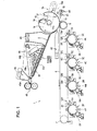
- Fig. 1 illustrates schematically and partially an image forming apparatus according to an embodiment of the invention.
- Fig. 2A is a partial perspective view of a secondary transferring portion of the image forming apparatus shown in Fig. 1 .
- Fig. 2B is an enlarged view of an IIB portion of the portion shown in Fig. 2A .
- Fig. 2C is a partial right side view of the apparatus shown in Fig. 2A .
- Fig. 3 is a drawing illustrating peeling of a recording medium from a secondary transfer roller after transference of an image onto the recording medium.
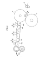
- Fig. 4 is a schematic illustration of the configuration of the secondary transfer portion to a fixing portion shown in Fig. 1 .
- Fig. 5 is a schematic illustration of an example of an image forming apparatus which is to be conceived from a past image forming apparatus.
- Fig. 6 is a schematic illustration of another example of an image forming apparatus which is to be conceived from a past image forming apparatus.
- FIG. 1 illustrates schematically and partially an image forming apparatus according to an embodiment of the invention.
- An image forming apparatus 1 of the embodiment is designed to form an image, by using liquid developer containing toner particles and carrier liquid.
- the liquid developer may have a composition in which toner particles including resin and pigments of an average particle size of about 0.1-5 ⁇ m are dispersed at a high density such as about 5-40wt% in nonvolatile and insulating carrier liquid such as silicone oil.
- carrier liquid such as silicone oil.
- Mineral oil or plant oil may be used as the carrier liquid in lieu of the silicone oil.
- the image forming apparatus 1 is provided with photosensitive members 2Y, 2M, 2C and 2K arranged in series horizontally or approximately horizontally as image carriers of yellow (Y), magenta (M), cyan (C), and black (K).
- Y yellow
- M magenta
- C cyan
- K black
- the letters Y, M, C and K are respectively used with other members to indicate that the members are associated with the above mentioned colors.
- Charging portions 3Y, 3M, 3C and 3K are respectively arranged around the photosensitive members 2Y, 2M, 2C and 2K.
- exposure portions 4Y, 4M, 4C and 4K exposure portions 4Y, 4M, 4C and 4K, developing portions 5Y, 5M, 5C and 5K, primary transferring portions 6Y, 6M, 6C and 6K, and photosensitive member cleaning portions 7Y, 7M, 7C and 7K are arranged in the described order.
- An image forming unit 1 of the exemplary embodiment is composed of the exposure portions 4Y, 4M, 4C and 4K, developing portions 5Y, 5M, 5C and 5K, primary transferring portions 6Y, 6M, 6C and 6K, and photosensitive member cleaning portions 7Y, 7M, 7C and 7K.
- the image forming apparatus 1 is provided with an endless intermediate transfer belt 8 as a image carrier.
- the intermediate transfer belt 8 is arranged above the photosensitive members 2Y, 2M, 2C and 2K.
- the intermediate transfer belt 8 is pressed against each photosensitive member 2Y, 2M, 2C and 2K at respective primary transfer portions 6Y, 6M, 6C and 6K.
- the intermediate transfer medium 8 is formed by a comparatively soft elastic belt having a three layer structure composed of a flexible substrate of resin or the like, an elastic layer of rubber or the like formed on the surface of the substrate and a top layer (not shown). Needless to say that the intermediate transfer belt 8 is not restricted to that structure and material.
- the intermediate transfer belt 8 is wound around an intermediate transfer belt tension roller 11 and an intermediate transfer belt driving roller 9 to which the driving force of a motor (not shown) is transmitted.
- the intermediate transfer belt 8 is arranged to turn in the direction shown by an arrow in the drawing with the intermediate transfer belt receiving tension. Note that the order of arrangement of the members such as the photosensitive members respectively associated with the colors Y, M, C and K is not restricted to that shown in Fig. 1 but may be set arbitrarily.
- Intermediate transfer belt squeeze devices 12Y, 12M, 12C and 12K are respectively arranged at positions along the intermediate transfer belt 8 in the vicinity of respective primary transfer portions 6Y, 6M, 6C and 6K and advanced in the direction in which the intermediate transfer belt turns from the respective primary transfer portions.
- a secondary transfer portion 13 serving as a transfer device is installed on the side of intermediate transfer belt driving roller 9 for the intermediate transfer belt 8.
- the secondary transfer portion 13 is provided with a secondary transfer roller 14 and a secondary transfer roller cleaning portion 15. Both end portions 14a of a rotational shaft of the secondary transfer roller 14 are rotatably supported by a pair of secondary transfer roller supporting frames 16.
- the secondary transfer roller supporting frames 16 swing about a rotary shaft 16a (rotational fulcrum) which is supported by a main body of the image forming apparatus (not shown) and which is urged by an urging means such as a spring (not shown) in the direction shown by an arrow shown in the secondary transfer roller 14.
- the pressing force of the urging means urges the secondary transfer roller 14 against the intermediate transfer belt 8.
- the intermediate transfer belt driving roller 9 functions as a back-up roller against the pressing of the secondary transfer roller 14.
- the secondary transfer roller 14 is formed with a recess 17. As shown in Fig. 2A , each of the recess 17 extends in an axial direction of the secondary transfer roller 14.
- the secondary transfer roller 14 has a sheet-shape elastic member 14c wound around the outer circumference of circular portion of the substrate 14b.
- the elastic member 14c serves as a frictional layer.
- a secondary transfer nip 13a is formed between the intermediate transfer belt 8 and the elastic member 14c of the intermediate transfer roller 14.
- a transfer bias for transferring a toner image, which has been transferred to the intermediate transfer belt 8, to the recording medium such as an image transfer sheet of paper.
- the secondary transfer roller 14 turns in the second direction as shown by the arrow and receives the transfer bias to transfer the toner image on the intermediate transfer belt 8 to the recording medium at the secondary transfer nip 13a.
- a gripper 18 serving as a recording medium gripping member and a gripper supporting portion 19 serving as a recording medium gripping portion receiving member on which the gripper 18 sits.
- ten grippers 18 are arranged along the axial direction (first direction) of the secondary transfer roller 14. Needless to say that the number of the grippers is not limited to ten, but may be determined arbitrarily.
- Each gripper is formed by bending a thin metal strip in two places so as to form portions of the same size and so as to have a crank shape.
- Each gripper 18 is arranged on the rotary shaft 20 to rotate integrally with the rotary shaft 20. Both end portions of the rotary shaft 20 are rotatably supported by supporting plates 21 and 22 which are arranged at positions opposing the recess 17 of the secondary transfer roller 14.
- the first gripper controlling cam follower 28 is installed on one end of the rotary shaft 20 by way of the first arm 26.
- a second gripper control cam follower 29 is installed on the other end of the rotary shaft 20 by way of the second arm 27.
- the first gripper control cam follower 28 is controlled by the first and third gripper control cams 30 and 31.
- the second gripper control cam follower 29 is controlled by a second gripper control cam (not shown) which is same as the first gripper control cam 30 and a fourth gripper control cam 32 which is the same as the third gripper control cam 31.
- the first and second gripper control cam followers 28 and 29 are controlled in synchronization with each other.
- Fig. 2A eight gripper supporting portions 19 are arranged in an axial direction of the secondary transfer roller 14. Note that the number of the gripper supporting portions is not limited to eight, but any number corresponding to the number of the grippers 18 may be employed.
- two gripper supporting portions 19a positioned at both ends of the secondary transfer roller 14 are longer in the axial direction than the other gripper supporting portions 19. With this arrangement, the gripper supporting portions 19a can cope with the size of the recording medium 33 in the axial direction of the secondary transfer roller 14.
- the gripper supporting portions 19, 19a are provided with gripper abutting portions 19b to which the grippers 18 come into abutment therewith.
- the gripper 18 corresponding to the gripper abutting portions 19b of the gripper supporting portions 19, 19a come into abutment with the gripper supporting portions 19, 19a and detach therefrom.
- the abutment and detachment of the grippers 18 with or from the gripper supporting portions 19, 19a are controlled by the first and second gripper control cam followers 28 and 29.
- a recording medium holding portion is composed of the grippers 18 and the gripper supporting portions 19 and 19a.
- the grippers 18 After the grippers 18 hold the recording medium 33, the recording medium 33 successively comes into abutment with an outer circumference of the secondary transfer roller 14 towards its rear end 33c. Further, under control of the first and second gripper control cam followers 28 and 29, the grippers 18 leave the gripper supporting portion 19 to release the front end 33a of the recording medium 33 after the recess 17 passes the position corresponding to the secondary transfer nip.
- the recess 17 When the recess 17 reaches a position where it opposes the intermediate transfer belt driving roller 9, the recess 17 of the secondary transfer roller 14 (actually, the recess portion) does not abut against the intermediate transfer belt 8. Accordingly, a secondary transfer nip 13a is not formed between the intermediate transfer belt 8 and secondary transfer roller 14. Therefore, the position of the secondary transfer nip 13a is defined as the position at which the secondary transfer roller 14 is pressed against the intermediate transfer belt 8 and the widths of the secondary transfer roller 14 and intermediate transfer belt 8 in their rotational direction become maximum.
- the rotation of the secondary transfer roller 14 at the time when the recording medium 33 is held has a vector component with the same direction as that of the movement of the recording medium 33 which is supplied from the gate roller 40. Accordingly, while the grippers 18 are apart from the gripper supporting portions 19, the front end portion 33a of the recording medium 33 moves as if chasing the moving grippers 18, and moves between the grippers 18 and gripper supporting portion 19. After that, the grippers 18 press the front end 33a of the recording medium 33 against the gripper supporting portions 19 so that the recording medium 33 is held.
- the toner image on the intermediate transfer belt 8 is transferred to the recording medium 33 at the secondary transfer nip 13a while the front end portion 33a of the recording medium 33 is held by the grippers 18 (transfer step).
- a circumferential length of the secondary transfer roller 14 except the width of the recess 17 in the rotational direction of the secondary transfer roller 14 is set to be larger than a length of a recording medium having the largest length in the moving direction among the plurality of recording media to be used in the image forming apparatus 1 of the exemplary embodiment. With this setting, the toner image on the intermediate transfer belt 8 is transferred without fail to the recording medium 33 having the maximum length.
- each gripper 18 When the front end portion 33a of the recording medium 33 held by each gripper 18 passes the secondary transfer nip 13a, each gripper 18 begins to move in the direction in which each gripper 18 separates from the gripper supporting portion 19 and the front end portion 33a of the recording medium 33 is released.
- protruding claws 34 as recording medium peeling members are disposed within the recess 17. As shown in Figs. 2A and 2B , nine protruding claws 34 are arranged along the axial direction of the secondary transfer roller 14. Needless to say that the number of the protruding claws 34 is not limited to nine but may be any number.
- the protruding claws 34 are each formed from a thin metal strip so as to have the same shape and the same size.
- the protruding claws 34 each performs rectilinear motion integrally with each other guided by a rectilinear guide hole formed on the supporting plates 21 and 22.
- a rotary shaft 35 is rotatably supported by the supporting plates 21 and 22. The rotation of the rotary shaft 35 is converted into the rectilinear motion of each protruding claw 34 by a motion converting mechanism (not shown) which is known by those skilled in the art.
- Each protruding claw 34 is configured to move rectilinearly between a retracted position as shown by a solid line in Fig. 2C and a protruding position as shown by a phantom line in the same drawing.
- all of the protruding claws 34 are positioned on the inner side of an imaginary contour line 14f, i.e., within the recess 17 when the protruding claws are in the retracted position, while the front ends of the protruding claws 34 protrude outside of the imaginary contour line 14, i.e., outside of the recess 17 when the claws 34 are in the protruding position.
- the protruding claws 34 do not abut against the back surface of the recording medium 33 when the protruding claws are in the retracted position, while the protruding claws 34 abut against the back surface of the recording medium 33 to push the recording medium 33 out of the outer circumference of the secondary transfer roller 14, i.e., peel the back of the recording medium 33 off of the outer circumference of the secondary transfer roller 14 when the protruding claws 34 are in the protruding position.
- a cam follower 38 that controls the first protruding claw is provided via an arm 37 on one end of a rotary shaft 35 which extends through the supporting plate 21.
- a cam follower (not shown) that controls a second protruding claw that is similar to the cam follower that controls the first protruding claw, is installed via an arm that is similar to the arm 37, on the other end of the rotary shaft 35 extending through the supporting plate 22.
- the second cam follower (not shown) that controls the second protruding claw is controlled by the second protruding claw control cam (not shown).
- the first and second cam followers that control the protruding claws are controlled synchronously.
- each protruding claw 34 moves to be in the protruding position before or after the release of the front end portion 33a of the recording medium 33 by the grippers 18, each protruding claw moves to be in the protruding position and peels off the back of the recording medium 33 from the outer circumference of the secondary transfer roller 14.
- each protruding claw 34 moves away from the back of the recording medium 33, and each protruding claw 34 moves to be in the retracted position.
- Each protruding claw is held in the retracted position until it moves to be in the protruding position before or after the release of the front end portion 33a of the recording medium 33 by the grippers 18 in a similar way at the time that the next image forming operation is to be performed.
- an abutting member supporting portion 23 is installed on one end of the secondary transfer roller 14 to integrally rotate with the secondary transfer roller 14.
- a first abutting member 24 serving as a first positioning member is placed on the abutting member supporting portion 23.
- the same abutting member supporting portion similar to the abutting member supporting portion 23 is provided on the other end of the secondary transfer roller 14, and a first abutting member 25 serving as the first positioning member is placed on the abutting member supporting portion.
- the respective first abutting members 24 and 25 rotate integrally with the secondary transfer roller 14.
- the first abutting members 24 and 25 have circular outer circumferences 24a and 25a which are coaxial with the circle of the outer circular circumference of the secondary transfer roller 14.
- second abutting members serving as second positioning members are respectively provided on a rotary shaft 9a at both ends of the intermediate transfer belt driving roller 9. Then, when the first abutting members 24 and 25 are at positions where they do not oppose respective second abutting members, the elastic member 14c of the secondary transfer roller 14 comes into abutment with the intermediate transfer belt 8 to form a secondary transfer nip 13a. In that case, the recess 17 of the secondary transfer roller 14 hardly opposes the secondary transfer nip corresponding position.
- the outer circumferences 24a and 25a of the first abutting members 24 and 25 come into abutment with corresponding second abutting members.
- some or all of the recess 17 of the secondary transfer roller 14 oppose the secondary transfer nip corresponding positions as mentioned above.
- the secondary transfer roller 14 does not significantly change its position relative to the intermediate transfer belt 8 and the intermediate transfer belt driving roller 9 and its position is maintained even if the recess 17 opposes the secondary transfer nip corresponding position.
- the secondary transfer roller cleaning portion 15 is provided with a cleaning member 15a such as cleaning blade or the like, and a liquid developer reclaim container 15b.
- the cleaning member 15a comes into abutment with the outer circumference of the elastic member 14c of the secondary transfer roller 14 to remove the liquid developer attached to the elastic member 14c.
- the liquid developer reclaim container 15b reclaims and stores the liquid developer removed by the cleaning member 15a.
- the image forming apparatus 1 is provided with a first air flow generating device 42, a second air flow generating device 43, a recording medium transporting portion 44, a third air flow generating device 45 and a fixing portion 46. All of the first air flow generating device 42, the second air flow generating device 43, the recording medium transporting portion 44, the third air flow generating device 45 and the fixing portion 46 are located vertically above the image forming unit and the intermediate transfer belt 8.
- the first air flow generating device 42 blows air, as indicated by an arrow in Fig. 3 , to the front end portion 33a of the recording medium 33 which has been released from the grippers 18. With this, the front end portion 33a of the recording medium 33 is prevented from moving along with the intermediate transfer belt 8.
- the second air flow generating device 43 is provided with an inhaling member 43a which has a guide plane 43a 1 , and an air flow generator 43b which inhales air.
- the inhaling member 43a is formed so as to have a box shape with its inner portion being hollow.
- a plurality of elongated inhaling holes are provided at the positions of the guide plane 43a 1 to communicate with the inside and outside of the inhaling member 43a.
- the recording medium 33 is transported while it is guided by the guide plane 43a 1 and is sucked and held by the inhaling member 43a by means of the air flow of the air suction of the air inhaling member 43a.
- an intermediate portion 33b of the recording medium 33 comes into abutment with the guide plane 43a 1 of the air flow generating device 43 while a rear end portion 33c of the recording medium 33 is pinched by the elastic member 14c of the secondary transfer roller 14 and the intermediate transfer belt 8. Accordingly, the recording medium 33 is transported to the recording medium transporting portion 44 by the rotational force of the intermediate transfer belt 8 and the secondary transfer roller 14 while the recording medium 33 is sucked up to the guide plane 43a 1 with a transfer plane 33d on which a toner image has been transferred, facing vertically downward.
- the recording medium transporting portion 44 is provided with a suction member 44b and an endless recording medium transporting belt 44a which turns in the direction shown by the arrow shown in Figs. 1 and 4 . As shown in Fig. 3 , the recording medium transporting belt 44a is formed with multiple air suction holes 44a 1 . The front end 33a of the recording medium 33 which has been guided and transported from the second air flow generating device 43, moves to the recording medium transport belt 44a of the recording medium transporting portion 44.
- the air suction member 44b sucks air in the direction shown by the arrows via the air suction holes 44a 1 of the recording medium transporting belt 44a.
- the recording medium 33 is transported by way of its back to the third air flow generating device 45 while it is sucked up and held by the air flow due to the air suction of the suction member 44b (recording medium transporting step). That is, the recording medium 33 is transported with its image transfer plane 33d facing vertically downward and the plane opposite the image transfer plane 33d is sucked up and held by air flow to the recording medium transporting belt 44a (recording medium transporting stage).
- the recording medium transporting belt 44a in Fig. 1 , is wound around three winding rollers while Fig. 4 shows that the recording medium transporting belt 44a is wound around two winding rollers 44c. This is for the sake of simplifying the drawing. Although Fig. 4 shows only two winding rollers 44c, the recording medium transporting belt 44a is wound around three winding rollers. As an alternative configuration, the recording medium transporting belt 44a shown in Fig. 1 may be wound around two winding rollers.
- the third air flow generating device 45 is provided with an air flow generating portion 45b and a suction member 45a which has a guide plane 45a 1 for guiding the recording medium 33.
- the suction member 45a is formed in the shape of a box whose inside is hollow. Although not shown in the drawings, a plurality of elongated suction holes are formed at the position of the guide plane 45a 1 of the suction member 45a to communicate with the outside and inside of the suction member 45a.
- the fixing portion 46 includes a heating roller 46a and a pressing roller 46b which is pressed against the heating roller 46a.
- the toner image on the recording medium 33 is pressed and heated by the heating roller 46a and pressing roller 46b and fixed (fixing step). After that the recording medium 33 is ejected onto an ejection tray (not shown).
- a general configuration and an image forming operation of the portion other than that of the above described present example are substantially the same as that of a conventional image forming apparatus, and explanation thereof is omitted.
- the image developed by a liquid developer including toner and carrier is transferred to the recording medium 33 at the secondary transfer portion 13.
- the carrier liquid included in the toner image penetrates into the coat layer and fiber layer of the recording medium 33. Consequently, the recording medium 33 which the carrier liquid has penetrated is filled with the carrier liquid so that its ventilation property decreases and the attracting force of the recording medium transporting belt 44a increases.
- the recording medium 33 is transported by the recording medium transporting belt 44a of the recording medium transport portion 44 with the image transfer plane 33d being sucked and held vertically downward by air flow. Accordingly, the gravitational effect which the recording medium 33 exerts on the recording medium transporting belt 44a, may be reduced.
- the image transfer medium 33 does not fall in the direction of gravity, thereby enabling stable transportation of the recording medium 33.
- cohesion or coagulation of the image forming unit due to the heat of the fixing portion 46 is avoided.
- nonvolatile carrier liquid is used for the carrier liquid of the liquid developer, the carrier liquid that penetrated the coat layer and the fiber layer of the recording medium 33 is held without volatilizing. With this, sucking and holding force for the recording medium transporting belt 44a of the recording medium transporting portion 44 are improved further, enabling stable transportation of the recording medium 33.
- the image forming apparatus and image forming method are not limited to the exemplary embodiment described above.
- the intermediate transfer belt 8 is used for the image carrier in the embodiment, an intermediate transfer drum may be used and a photosensor may be used for the image carrier.
- the photosensor is used for the image carrier, the toner image on the photosensor is directly transferred to the recording medium.
- the image forming apparatus of each exemplary embodiment is series type image forming apparatus, the apparatus may be of another type or may be of monochrome type. In short, variations and modifications may be made within the scope described in the claims.
Landscapes
- Physics & Mathematics (AREA)
- General Physics & Mathematics (AREA)
- Electrostatic Charge, Transfer And Separation In Electrography (AREA)
- Wet Developing In Electrophotography (AREA)
Abstract
Description
- The present invention relates to an image forming apparatus and an image forming method of an electrophotography type in which a recording medium is transported by a recording medium transporting portion with the recording medium being sucked and held after an image has been transferred thereon.
-
JP-A-6-135613 - In the image forming apparatus as described in
JP-A-6-135613
the recording medium transporting belt is arranged in a horizontal direction with respect to the image transfer portion. Therefore, a large space is required in the horizontal direction for accommodating the recording medium transporting portion. In particular, in the case of an image forming apparatus having an intermediate transferring belt and image forming units of four colors arranged in tandem manner as shown inFig. 5 , the space required in the horizontal direction, i.e., in the recording medium transporting direction, becomes even larger under the condition where the recording medium transporting belt is arranged in a horizontal direction with respect to a second transfer portion. - Accordingly, it may be considered that the recording medium transporting portion is arranged vertically with respect to the image forming unit to reduce the horizontal space. As mentioned above, if the horizontal space is to be small for the installment of the recording medium transporting portion which transports the recording medium by the recording medium transporting belt with the image transferred surface facing vertically upwards, the recording medium transporting portion must be located vertically below the image forming unit in consideration of transfer operation for a recording medium transported through a transporting path shown in
Fig. 6 . For this reason, the fixing portion is to be positioned vertically below the image forming unit. However, if the fixing portion is positioned vertically below the image forming unit, it is likely that the toner in the image forming unit will coagulate due to the heat of the fixing portion. - Additionally, if the recording medium transporting belt is positioned vertically above the recording medium, the recording medium is not stably sucked to the recording medium transporting belt due to gravity and failure to transport the recording medium as desired is likely to occur.
- An advantage of some aspects of the invention is that it provides an image forming apparatus which is compact and which has a recording medium transporting belt that transports a recording medium as desired while inhibiting coagulation of toner in the image forming unit.
- Another advantage of some other aspects of the invention is that it provides an image forming method which enables an image forming apparatus to be compact and to transport a recording medium as desired without occurrence of coagulation of toner in an image forming unit.
- According to an aspect of the invention, in an image forming apparatus and an image forming method, an image developed by liquid developer containing toner and carrier liquid is transferred to a recording medium at a transferring portion. At that time, the carrier liquid contained in the toner image permeates to a coat layer and fibrous layer. Consequently, in the recording medium to which the carrier liquid has permeated, spaces of the coat layer and fibrous layer are filled with the carrier liquid so that a ventilation property of the recording medium deteriorates thereby increasing the sucking and holding force. In addition, the recording medium transporting portion may be configured such that the recording medium is transported while it is sucked and held vertically upwards by the air flow over the surface opposite the image transferring surface with the image transfer surface facing vertically downwards. With this structure, even if the recording medium transporting portion is located above the image forming unit and directly above the recording medium, the recording medium is not likely to drop downwards, thereby enabling stable transportation of the recording medium. In addition, as the recording medium transporting portion is located above the image forming unit, it is possible that coagulation and concretion of the toner in the image forming unit is prevented.
- In another aspect of the invention, as non-volatile oil (non-volatile carrier liquid) is used for the carrier liquid of the liquid developing agent, the carrier liquid permeated to the coat layer and fibrous layer is held in those layers without volatilizing. With this structure, the sucking and holding force for transporting the recording medium is improved further, thereby enabling stable transportation of the recording medium.
- The invention will be described with reference to the accompanying drawings, wherein like numbers reference like elements.
-
Fig. 1 illustrates schematically and partially an image forming apparatus according to an embodiment of the invention. -
Fig. 2A is a partial perspective view of a secondary transferring portion of the image forming apparatus shown inFig. 1 . -
Fig. 2B is an enlarged view of an IIB portion of the portion shown inFig. 2A . -
Fig. 2C is a partial right side view of the apparatus shown inFig. 2A . -
Fig. 3 is a drawing illustrating peeling of a recording medium from a secondary transfer roller after transference of an image onto the recording medium. -
Fig. 4 is a schematic illustration of the configuration of the secondary transfer portion to a fixing portion shown inFig. 1 . -
Fig. 5 is a schematic illustration of an example of an image forming apparatus which is to be conceived from a past image forming apparatus. -
Fig. 6 is a schematic illustration of another example of an image forming apparatus which is to be conceived from a past image forming apparatus. - An embodiment of the invention will be described hereinafter with reference to the accompanying drawings.
Fig. 1 illustrates schematically and partially an image forming apparatus according to an embodiment of the invention. - An image forming apparatus 1 of the embodiment is designed to form an image, by using liquid developer containing toner particles and carrier liquid. The liquid developer may have a composition in which toner particles including resin and pigments of an average particle size of about 0.1-5µm are dispersed at a high density such as about 5-40wt% in nonvolatile and insulating carrier liquid such as silicone oil. Mineral oil or plant oil may be used as the carrier liquid in lieu of the silicone oil.
- As shown in
Fig. 1 , the image forming apparatus 1 is provided withphotosensitive members photosensitive members - Charging
portions photosensitive members photosensitive members exposure portions portions portions member cleaning portions exposure portions portions portions member cleaning portions - The image forming apparatus 1 is provided with an endless
intermediate transfer belt 8 as a image carrier. Theintermediate transfer belt 8 is arranged above thephotosensitive members intermediate transfer belt 8 is pressed against eachphotosensitive member primary transfer portions - The
intermediate transfer medium 8 is formed by a comparatively soft elastic belt having a three layer structure composed of a flexible substrate of resin or the like, an elastic layer of rubber or the like formed on the surface of the substrate and a top layer (not shown). Needless to say that theintermediate transfer belt 8 is not restricted to that structure and material. Theintermediate transfer belt 8 is wound around an intermediate transferbelt tension roller 11 and an intermediate transferbelt driving roller 9 to which the driving force of a motor (not shown) is transmitted. Theintermediate transfer belt 8 is arranged to turn in the direction shown by an arrow in the drawing with the intermediate transfer belt receiving tension. Note that the order of arrangement of the members such as the photosensitive members respectively associated with the colors Y, M, C and K is not restricted to that shown inFig. 1 but may be set arbitrarily. - Intermediate transfer
belt squeeze devices intermediate transfer belt 8 in the vicinity of respectiveprimary transfer portions secondary transfer portion 13 serving as a transfer device is installed on the side of intermediate transferbelt driving roller 9 for theintermediate transfer belt 8. - The
secondary transfer portion 13 is provided with asecondary transfer roller 14 and a secondary transferroller cleaning portion 15. Bothend portions 14a of a rotational shaft of thesecondary transfer roller 14 are rotatably supported by a pair of secondary transfer roller supporting frames 16. The secondary transferroller supporting frames 16 swing about arotary shaft 16a (rotational fulcrum) which is supported by a main body of the image forming apparatus (not shown) and which is urged by an urging means such as a spring (not shown) in the direction shown by an arrow shown in thesecondary transfer roller 14. The pressing force of the urging means urges thesecondary transfer roller 14 against theintermediate transfer belt 8. At that time, the intermediate transferbelt driving roller 9 functions as a back-up roller against the pressing of thesecondary transfer roller 14. - Further, the
secondary transfer roller 14 is formed with arecess 17. As shown inFig. 2A , each of therecess 17 extends in an axial direction of thesecondary transfer roller 14. Thesecondary transfer roller 14 has a sheet-shapeelastic member 14c wound around the outer circumference of circular portion of thesubstrate 14b. Theelastic member 14c serves as a frictional layer. As shown inFig. 1 andFig. 3 , a secondary transfer nip 13a is formed between theintermediate transfer belt 8 and theelastic member 14c of theintermediate transfer roller 14. - To the
secondary transfer roller 14 is applied a transfer bias for transferring a toner image, which has been transferred to theintermediate transfer belt 8, to the recording medium such as an image transfer sheet of paper. When theintermediate transfer belt 8 turns in the direction shown by the arrow, thesecondary transfer roller 14 turns in the second direction as shown by the arrow and receives the transfer bias to transfer the toner image on theintermediate transfer belt 8 to the recording medium at the secondary transfer nip 13a. - In the
recess 17 are located agripper 18 serving as a recording medium gripping member and agripper supporting portion 19 serving as a recording medium gripping portion receiving member on which thegripper 18 sits. As shown inFigs. 2A and 2B , tengrippers 18 are arranged along the axial direction (first direction) of thesecondary transfer roller 14. Needless to say that the number of the grippers is not limited to ten, but may be determined arbitrarily. Each gripper is formed by bending a thin metal strip in two places so as to form portions of the same size and so as to have a crank shape. - Each
gripper 18 is arranged on therotary shaft 20 to rotate integrally with therotary shaft 20. Both end portions of therotary shaft 20 are rotatably supported by supportingplates recess 17 of thesecondary transfer roller 14. - The first gripper controlling
cam follower 28 is installed on one end of therotary shaft 20 by way of thefirst arm 26. A second grippercontrol cam follower 29 is installed on the other end of therotary shaft 20 by way of thesecond arm 27. When thesecondary transfer roller 14 rotates, the first grippercontrol cam follower 28 is controlled by the first and thirdgripper control cams secondary transfer roller 14 rotates, the second grippercontrol cam follower 29 is controlled by a second gripper control cam (not shown) which is same as the firstgripper control cam 30 and a fourthgripper control cam 32 which is the same as the thirdgripper control cam 31. The first and second grippercontrol cam followers - As shown in
Fig. 2A , eightgripper supporting portions 19 are arranged in an axial direction of thesecondary transfer roller 14. Note that the number of the gripper supporting portions is not limited to eight, but any number corresponding to the number of thegrippers 18 may be employed. - Of the eight
gripper supporting portions 19, twogripper supporting portions 19a positioned at both ends of thesecondary transfer roller 14 are longer in the axial direction than the othergripper supporting portions 19.
With this arrangement, thegripper supporting portions 19a can cope with the size of therecording medium 33 in the axial direction of thesecondary transfer roller 14. - As shown in
Figs. 2B and 2C , thegripper supporting portions gripper abutting portions 19b to which thegrippers 18 come into abutment therewith. Thegripper 18 corresponding to thegripper abutting portions 19b of thegripper supporting portions gripper supporting portions grippers 18 with or from thegripper supporting portions control cam followers - That is, as shown in
Fig. 2C , when thefront end 33a of therecording medium 33 which is supplied from thegate roller 40 via a recordingmedium supply guide 41, comes into abutment with steppedportions 18c of thegrippers 18, under control of the first and second cam followers thegrippers 18 hold thefront end 33a between thegrippers 18 and thegripper abutting portions 19b of thegripper supporting portions recording medium 33 is carried out just before therecess 17 reaches a position corresponding to the secondary transfer nip. Thus, a recording medium holding portion is composed of thegrippers 18 and thegripper supporting portions - After the
grippers 18 hold therecording medium 33, therecording medium 33 successively comes into abutment with an outer circumference of thesecondary transfer roller 14 towards itsrear end 33c. Further, under control of the first and second grippercontrol cam followers grippers 18 leave thegripper supporting portion 19 to release thefront end 33a of therecording medium 33 after therecess 17 passes the position corresponding to the secondary transfer nip. - When the
recess 17 reaches a position where it opposes the intermediate transferbelt driving roller 9, therecess 17 of the secondary transfer roller 14 (actually, the recess portion) does not abut against theintermediate transfer belt 8. Accordingly, a secondary transfer nip 13a is not formed between theintermediate transfer belt 8 andsecondary transfer roller 14. Therefore, the position of the secondary transfer nip 13a is defined as the position at which thesecondary transfer roller 14 is pressed against theintermediate transfer belt 8 and the widths of thesecondary transfer roller 14 andintermediate transfer belt 8 in their rotational direction become maximum. - The rotation of the
secondary transfer roller 14 at the time when therecording medium 33 is held, has a vector component with the same direction as that of the movement of therecording medium 33 which is supplied from thegate roller 40. Accordingly, while thegrippers 18 are apart from thegripper supporting portions 19, thefront end portion 33a of therecording medium 33 moves as if chasing the movinggrippers 18, and moves between thegrippers 18 andgripper supporting portion 19. After that, thegrippers 18 press thefront end 33a of therecording medium 33 against thegripper supporting portions 19 so that therecording medium 33 is held. - When the holding portion at the distal end of the
grippers 18 holds thefront end portion 33a of therecording medium 33 between thegrippers 18 and thegripper supporting portions 19 as shown by a phantom line inFig. 2C , all of thegrippers 18 are to retract to the inside of animaginary contour line 14f of theelastic member 14c of thesecondary transfer roller 14. When thegrippers 18 are in the release position as shown by a solid line inFig. 2C , the holding portion at the front end side of thegrippers 18 projects to the outer side of theimaginary contour line 14f. - The toner image on the
intermediate transfer belt 8 is transferred to therecording medium 33 at the secondary transfer nip 13a while thefront end portion 33a of therecording medium 33 is held by the grippers 18 (transfer step). A circumferential length of thesecondary transfer roller 14 except the width of therecess 17 in the rotational direction of thesecondary transfer roller 14 is set to be larger than a length of a recording medium having the largest length in the moving direction among the plurality of recording media to be used in the image forming apparatus 1 of the exemplary embodiment. With this setting, the toner image on theintermediate transfer belt 8 is transferred without fail to therecording medium 33 having the maximum length. - When the
front end portion 33a of therecording medium 33 held by each gripper 18 passes the secondary transfer nip 13a, eachgripper 18 begins to move in the direction in which eachgripper 18 separates from thegripper supporting portion 19 and thefront end portion 33a of therecording medium 33 is released. - Additionally, protruding
claws 34 as recording medium peeling members are disposed within therecess 17.
As shown inFigs. 2A and 2B , nine protrudingclaws 34 are arranged along the axial direction of thesecondary transfer roller 14. Needless to say that the number of the protrudingclaws 34 is not limited to nine but may be any number. The protrudingclaws 34 are each formed from a thin metal strip so as to have the same shape and the same size. The protrudingclaws 34 each performs rectilinear motion integrally with each other guided by a rectilinear guide hole formed on the supportingplates rotary shaft 35 is rotatably supported by the supportingplates rotary shaft 35 is converted into the rectilinear motion of each protrudingclaw 34 by a motion converting mechanism (not shown) which is known by those skilled in the art. - Each protruding
claw 34 is configured to move rectilinearly between a retracted position as shown by a solid line inFig. 2C and a protruding position as shown by a phantom line in the same drawing. In that case, all of the protrudingclaws 34 are positioned on the inner side of animaginary contour line 14f, i.e., within therecess 17 when the protruding claws are in the retracted position, while the front ends of the protrudingclaws 34 protrude outside of theimaginary contour line 14, i.e., outside of therecess 17 when theclaws 34 are in the protruding position. Then, the protrudingclaws 34 do not abut against the back surface of therecording medium 33 when the protruding claws are in the retracted position, while the protrudingclaws 34 abut against the back surface of therecording medium 33 to push therecording medium 33 out of the outer circumference of thesecondary transfer roller 14, i.e., peel the back of therecording medium 33 off of the outer circumference of thesecondary transfer roller 14 when the protrudingclaws 34 are in the protruding position. - As shown in
Figs. 2A and3 , acam follower 38 that controls the first protruding claw is provided via anarm 37 on one end of arotary shaft 35 which extends through the supportingplate 21. A cam follower (not shown) that controls a second protruding claw that is similar to the cam follower that controls the first protruding claw, is installed via an arm that is similar to thearm 37, on the other end of therotary shaft 35 extending through the supportingplate 22. When thesecondary transfer roller 14 rotates, thecam follower 38 that controls the first protruding claw is controlled by the first protrudingclaw control cam 39. Also, when thesecondary transfer roller 14 rotates, the second cam follower (not shown) that controls the second protruding claw is controlled by the second protruding claw control cam (not shown). The first and second cam followers that control the protruding claws are controlled synchronously. - As shown in
Fig. 3 , after thesecondary transfer roller 14 rotates and therecess 17 has passed the secondary nip corresponding position, each protrudingclaw 34 moves to be in the protruding position before or after the release of thefront end portion 33a of therecording medium 33 by thegrippers 18, each protruding claw moves to be in the protruding position and peels off the back of therecording medium 33 from the outer circumference of thesecondary transfer roller 14. When thesecondary transfer roller 14 rotates further, each protrudingclaw 34 moves away from the back of therecording medium 33, and each protrudingclaw 34 moves to be in the retracted position. Each protruding claw is held in the retracted position until it moves to be in the protruding position before or after the release of thefront end portion 33a of therecording medium 33 by thegrippers 18 in a similar way at the time that the next image forming operation is to be performed. - As shown if
Fig. 2A , an abuttingmember supporting portion 23 is installed on one end of thesecondary transfer roller 14 to integrally rotate with thesecondary transfer roller 14. A first abuttingmember 24 serving as a first positioning member is placed on the abuttingmember supporting portion 23. In the same way, the same abutting member supporting portion similar to the abuttingmember supporting portion 23 is provided on the other end of thesecondary transfer roller 14, and a first abuttingmember 25 serving as the first positioning member is placed on the abutting member supporting portion. The respective first abuttingmembers secondary transfer roller 14. The first abuttingmembers outer circumferences secondary transfer roller 14. - Although not shown in the drawings, second abutting members serving as second positioning members are respectively provided on a rotary shaft 9a at both ends of the intermediate transfer
belt driving roller 9. Then, when the first abuttingmembers elastic member 14c of thesecondary transfer roller 14 comes into abutment with theintermediate transfer belt 8 to form a secondary transfer nip 13a. In that case, therecess 17 of thesecondary transfer roller 14 hardly opposes the secondary transfer nip corresponding position. - When the first abutting
members outer circumferences members recess 17 of thesecondary transfer roller 14 oppose the secondary transfer nip corresponding positions as mentioned above. In this way, as the first abuttingmembers secondary transfer roller 14 does not significantly change its position relative to theintermediate transfer belt 8 and the intermediate transferbelt driving roller 9 and its position is maintained even if therecess 17 opposes the secondary transfer nip corresponding position. - The secondary transfer
roller cleaning portion 15 is provided with a cleaning member 15a such as cleaning blade or the like, and a liquid developer reclaim container 15b. The cleaning member 15a comes into abutment with the outer circumference of theelastic member 14c of thesecondary transfer roller 14 to remove the liquid developer attached to theelastic member 14c. The liquid developer reclaim container 15b reclaims and stores the liquid developer removed by the cleaning member 15a. - Further, as shown in
Figs. 1 and4 , the image forming apparatus 1 is provided with a first airflow generating device 42, a second airflow generating device 43, a recordingmedium transporting portion 44, a third airflow generating device 45 and a fixingportion 46. All of the first airflow generating device 42, the second airflow generating device 43, the recordingmedium transporting portion 44, the third airflow generating device 45 and the fixingportion 46 are located vertically above the image forming unit and theintermediate transfer belt 8. The first airflow generating device 42 blows air, as indicated by an arrow inFig. 3 , to thefront end portion 33a of therecording medium 33 which has been released from thegrippers 18. With this, thefront end portion 33a of therecording medium 33 is prevented from moving along with theintermediate transfer belt 8. - As shown in
Figs. 3 and4 , the second airflow generating device 43 is provided with an inhalingmember 43a which has aguide plane 43a1, and anair flow generator 43b which inhales air. The inhalingmember 43a is formed so as to have a box shape with its inner portion being hollow. Although not shown in the drawings, a plurality of elongated inhaling holes are provided at the positions of theguide plane 43a1 to communicate with the inside and outside of the inhalingmember 43a. - The
front end 33a of therecording medium 33 which has been peeled off thesecondary transfer roller 14, moves to theguide plane 43a1 of the inhalingmember 43a. Then, air is absorbed in the direction shown by the arrow inFig. 3 through respective air suction holes of the inhalingmember 43a by means of the airflow generating member 43b. Therecording medium 33 is transported while it is guided by theguide plane 43a1 and is sucked and held by the inhalingmember 43a by means of the air flow of the air suction of theair inhaling member 43a. At that time, anintermediate portion 33b of therecording medium 33 comes into abutment with theguide plane 43a1 of the airflow generating device 43 while arear end portion 33c of therecording medium 33 is pinched by theelastic member 14c of thesecondary transfer roller 14 and theintermediate transfer belt 8. Accordingly, therecording medium 33 is transported to the recordingmedium transporting portion 44 by the rotational force of theintermediate transfer belt 8 and thesecondary transfer roller 14 while therecording medium 33 is sucked up to theguide plane 43a1 with atransfer plane 33d on which a toner image has been transferred, facing vertically downward. - The recording
medium transporting portion 44 is provided with asuction member 44b and an endless recordingmedium transporting belt 44a which turns in the direction shown by the arrow shown inFigs. 1 and4 . As shown inFig. 3 , the recordingmedium transporting belt 44a is formed with multipleair suction holes 44a1. Thefront end 33a of therecording medium 33 which has been guided and transported from the second airflow generating device 43, moves to the recordingmedium transport belt 44a of the recordingmedium transporting portion 44. - As shown in
Figs. 1 ,3 and4 , theair suction member 44b sucks air in the direction shown by the arrows via theair suction holes 44a1 of the recordingmedium transporting belt 44a. Therecording medium 33 is transported by way of its back to the third airflow generating device 45 while it is sucked up and held by the air flow due to the air suction of thesuction member 44b (recording medium transporting step). That is, therecording medium 33 is transported with itsimage transfer plane 33d facing vertically downward and the plane opposite theimage transfer plane 33d is sucked up and held by air flow to the recordingmedium transporting belt 44a (recording medium transporting stage). - Note that the recording
medium transporting belt 44a, inFig. 1 , is wound around three winding rollers whileFig. 4 shows that the recordingmedium transporting belt 44a is wound around two windingrollers 44c. This is for the sake of simplifying the drawing. AlthoughFig. 4 shows only two windingrollers 44c, the recordingmedium transporting belt 44a is wound around three winding rollers. As an alternative configuration, the recordingmedium transporting belt 44a shown inFig. 1 may be wound around two winding rollers. - As shown in
Figs. 1 and4 , the third airflow generating device 45 is provided with an airflow generating portion 45b and asuction member 45a which has aguide plane 45a1 for guiding therecording medium 33. Thesuction member 45a is formed in the shape of a box whose inside is hollow. Although not shown in the drawings, a plurality of elongated suction holes are formed at the position of theguide plane 45a1 of thesuction member 45a to communicate with the outside and inside of thesuction member 45a. - The
front end portion 33a of therecording medium 33 which has been transported from the recordingmedium transporting belt 44a, moves to theguide plane 45a1 of thesuction member 45a. Then, thesuction member 45b sucks air in the direction indicated by an arrow shown inFigs. 1 and4 through the suction holes of thesuction member 45a. By means of the air flow of thesuction member 45a, therecording medium 33 is sucked up and guided to theguide plane 45a1 of thesuction member 45a with theimage transfer plane 33d facing vertically downwards, and is guided to the fixingportion 46 by a transporting force of the recordingmedium transporting belt 44a. - The fixing
portion 46 includes aheating roller 46a and apressing roller 46b which is pressed against theheating roller 46a. Thus, the toner image on therecording medium 33 is pressed and heated by theheating roller 46a andpressing roller 46b and fixed (fixing step). After that therecording medium 33 is ejected onto an ejection tray (not shown). - A general configuration and an image forming operation of the portion other than that of the above described present example are substantially the same as that of a conventional image forming apparatus, and explanation thereof is omitted.
- According to an aspect of the image forming apparatus 1 of the above described exemplary embodiment, the image developed by a liquid developer including toner and carrier, is transferred to the
recording medium 33 at thesecondary transfer portion 13. At that time, the carrier liquid included in the toner image penetrates into the coat layer and fiber layer of therecording medium 33. Consequently, therecording medium 33 which the carrier liquid has penetrated is filled with the carrier liquid so that its ventilation property decreases and the attracting force of the recordingmedium transporting belt 44a increases. Moreover, therecording medium 33 is transported by the recordingmedium transporting belt 44a of the recordingmedium transport portion 44 with theimage transfer plane 33d being sucked and held vertically downward by air flow. Accordingly, the gravitational effect which therecording medium 33 exerts on the recordingmedium transporting belt 44a, may be reduced. With this operation, even in the case when the recordingmedium transporting belt 44a is located above the image forming unit, theimage transfer medium 33 does not fall in the direction of gravity, thereby enabling stable transportation of therecording medium 33. In addition, as the recordingmedium transporting belt 44a is located above the image forming unit, cohesion or coagulation of the image forming unit due to the heat of the fixingportion 46 is avoided. - Still further, as nonvolatile carrier liquid is used for the carrier liquid of the liquid developer, the carrier liquid that penetrated the coat layer and the fiber layer of the
recording medium 33 is held without volatilizing. With this, sucking and holding force for the recordingmedium transporting belt 44a of the recordingmedium transporting portion 44 are improved further, enabling stable transportation of therecording medium 33. - Note that the image forming apparatus and image forming method are not limited to the exemplary embodiment described above. For example, although the
intermediate transfer belt 8 is used for the image carrier in the embodiment, an intermediate transfer drum may be used and a photosensor may be used for the image carrier. When the photosensor is used for the image carrier, the toner image on the photosensor is directly transferred to the recording medium. Although the image forming apparatus of each exemplary embodiment is series type image forming apparatus, the apparatus may be of another type or may be of monochrome type. In short, variations and modifications may be made within the scope described in the claims.
Claims (6)
- An image forming apparatus comprising
a developing portion for developing a recording medium with liquid developer including toner and carrier liquid;
a transfer portion for transferring the image developed in the developing portion onto the recording medium: and
recording medium transporting portion for transporting the recording medium onto which the image has been transferred, with the transfer plane of the recording medium facing vertically downward and the plane opposite the image transfer plane being sucked and held by air flow. - An image forming apparatus according to claim 1,
wherein the carrier liquid is nonvolatile oil. - An image forming apparatus according to claim 1 further comprising a fixing portion for fixing the recording medium transported by the recording medium transporting portion.
- An image forming apparatus according to claim 1
wherein the recording medium transporting portion includes a transporting belt having air flow holes that allow air to flow therethrough. - An image forming apparatus according to claim 1
wherein the transfer portion includes a transfer roller serving as a recording medium gripping member for gripping the recording medium. - An image forming method comprising:developing an image on a recording medium by using a liquid developer including toner and carrier liquid;transferring the image developed on a latent image carrier to the recording medium;transporting the recording medium onto which the image has been transferred, with the transfer plane facing vertically downward and sucking by air flow and holding a plane opposite the image transfer plane; andfixing the transferred image on the recording medium.
Applications Claiming Priority (1)
| Application Number | Priority Date | Filing Date | Title |
|---|---|---|---|
| JP2009103668A JP2010256442A (en) | 2009-04-22 | 2009-04-22 | Image forming apparatus and image forming method |
Publications (2)
| Publication Number | Publication Date |
|---|---|
| EP2244130A2 true EP2244130A2 (en) | 2010-10-27 |
| EP2244130A3 EP2244130A3 (en) | 2011-04-06 |
Family
ID=42144806
Family Applications (1)
| Application Number | Title | Priority Date | Filing Date |
|---|---|---|---|
| EP10160428A Withdrawn EP2244130A3 (en) | 2009-04-22 | 2010-04-20 | Image forming apparatus and image forming method |
Country Status (4)
| Country | Link |
|---|---|
| US (1) | US20100272472A1 (en) |
| EP (1) | EP2244130A3 (en) |
| JP (1) | JP2010256442A (en) |
| CN (1) | CN101872145A (en) |
Families Citing this family (2)
| Publication number | Priority date | Publication date | Assignee | Title |
|---|---|---|---|---|
| JP2011145592A (en) * | 2010-01-18 | 2011-07-28 | Seiko Epson Corp | Image forming apparatus and image forming method |
| JP7139979B2 (en) * | 2019-01-31 | 2022-09-21 | 富士フイルムビジネスイノベーション株式会社 | Fixing device, image forming device |
Citations (1)
| Publication number | Priority date | Publication date | Assignee | Title |
|---|---|---|---|---|
| JPH06135613A (en) | 1992-10-22 | 1994-05-17 | Fuji Xerox Co Ltd | Paper sheet conveying device in copying machine |
Family Cites Families (14)
| Publication number | Priority date | Publication date | Assignee | Title |
|---|---|---|---|---|
| US3743403A (en) * | 1971-12-30 | 1973-07-03 | Xerox Corp | Transport assembly |
| US4410263A (en) * | 1982-03-01 | 1983-10-18 | Eastman Kodak Company | Sheet handling device for image transfer in an electrographic copier |
| US4403847A (en) * | 1982-03-29 | 1983-09-13 | Eastman Kodak Company | Electrographic transfer apparatus |
| JPS63284571A (en) * | 1987-05-18 | 1988-11-21 | Fujitsu Ltd | Electrophotographic recorder |
| US4914482A (en) * | 1989-02-06 | 1990-04-03 | Xerox Corporation | Sheet transport system |
| US5166735A (en) * | 1992-06-05 | 1992-11-24 | Xerox Corporation | Sheet buckle sensing |
| AU2578495A (en) * | 1994-10-11 | 1996-05-02 | Indigo N.V. | Imaging apparatus and intermediate transfer blanket therefor |
| US6026276A (en) * | 1997-09-29 | 2000-02-15 | Xerox Corp | Apparatus for handling color transparencies using vacuum switching |
| EP1450213B1 (en) * | 2003-02-20 | 2008-12-17 | Eastman Kodak Company | Fuser entry guide with variable vacuum for an electrophotographic machine |
| JP4185788B2 (en) * | 2003-03-07 | 2008-11-26 | 株式会社リコー | Image forming apparatus |
| JP4604791B2 (en) * | 2005-03-25 | 2011-01-05 | 富士ゼロックス株式会社 | Image forming apparatus |
| JP5162997B2 (en) * | 2007-07-31 | 2013-03-13 | コニカミノルタビジネステクノロジーズ株式会社 | Image forming apparatus |
| US8185020B2 (en) * | 2007-07-31 | 2012-05-22 | Konica Minolta Business Technologies, Inc. | Image forming apparatus and method for forming image with fine pigment and thermoplastic fine resin particles in a carrier liquid |
| JP2010197724A (en) * | 2009-02-25 | 2010-09-09 | Seiko Epson Corp | Transfer apparatus, image forming apparatus and image forming method |
-
2009
- 2009-04-22 JP JP2009103668A patent/JP2010256442A/en not_active Withdrawn
-
2010
- 2010-04-20 EP EP10160428A patent/EP2244130A3/en not_active Withdrawn
- 2010-04-21 US US12/764,229 patent/US20100272472A1/en not_active Abandoned
- 2010-04-22 CN CN201010168138A patent/CN101872145A/en active Pending
Patent Citations (1)
| Publication number | Priority date | Publication date | Assignee | Title |
|---|---|---|---|---|
| JPH06135613A (en) | 1992-10-22 | 1994-05-17 | Fuji Xerox Co Ltd | Paper sheet conveying device in copying machine |
Also Published As
| Publication number | Publication date |
|---|---|
| EP2244130A3 (en) | 2011-04-06 |
| JP2010256442A (en) | 2010-11-11 |
| CN101872145A (en) | 2010-10-27 |
| US20100272472A1 (en) | 2010-10-28 |
Similar Documents
| Publication | Publication Date | Title |
|---|---|---|
| JP5188029B2 (en) | Fixing device and image forming apparatus having the same | |
| US20070206981A1 (en) | Fusing apparatus including a sheet centering stripper assembly | |
| JP2010249990A (en) | Image forming apparatus and image forming method | |
| US6782228B1 (en) | Intermittent stripper fingers and baffle for stripping copy media from a heated fuser roll | |
| JP2011237555A (en) | Fixing device and image-forming apparatus having the same | |
| JP2010170004A (en) | Image forming apparatus and image forming method | |
| US8594545B2 (en) | Image-forming device and image-forming method | |
| EP2244130A2 (en) | Image forming apparatus and image forming method | |
| US7676187B2 (en) | Enhanced fuser stripping system | |
| US20100266317A1 (en) | Image forming apparatus and image forming method | |
| US20080101827A1 (en) | Image Fixation Apparatus, Image Formation Apparatus Having the Image Fixation Apparatus, and Image Fixation Method | |
| JP5998706B2 (en) | Fixing apparatus and image forming apparatus | |
| JP2010256441A (en) | Image forming apparatus and image forming method | |
| JP4311012B2 (en) | Fixing device | |
| JP2002365946A (en) | Image forming device | |
| US7092665B2 (en) | Fixing apparatus having an exfoliating member and a restricting member | |
| JP5273374B2 (en) | Image forming apparatus and image forming method | |
| JP2010170005A (en) | Image forming apparatus and image forming method | |
| US20110076066A1 (en) | Fixing apparatus and image forming apparatus | |
| JP5403223B2 (en) | Image forming method and image forming apparatus | |
| JP2011112910A (en) | Apparatus and method for forming image | |
| JP2010250216A (en) | Image forming apparatus and image forming method | |
| JP2011186197A (en) | Fixing device and image forming apparatus | |
| JP2010250215A (en) | Image forming apparatus and image forming method | |
| JP2010256440A (en) | Image forming apparatus and image forming method |
Legal Events
| Date | Code | Title | Description |
|---|---|---|---|
| PUAI | Public reference made under article 153(3) epc to a published international application that has entered the european phase |
Free format text: ORIGINAL CODE: 0009012 |
|
| AK | Designated contracting states |
Kind code of ref document: A2 Designated state(s): AT BE BG CH CY CZ DE DK EE ES FI FR GB GR HR HU IE IS IT LI LT LU LV MC MK MT NL NO PL PT RO SE SI SK SM TR |
|
| AX | Request for extension of the european patent |
Extension state: AL BA ME RS |
|
| PUAL | Search report despatched |
Free format text: ORIGINAL CODE: 0009013 |
|
| AK | Designated contracting states |
Kind code of ref document: A3 Designated state(s): AT BE BG CH CY CZ DE DK EE ES FI FR GB GR HR HU IE IS IT LI LT LU LV MC MK MT NL NO PL PT RO SE SI SK SM TR |
|
| AX | Request for extension of the european patent |
Extension state: AL BA ME RS |
|
| STAA | Information on the status of an ep patent application or granted ep patent |
Free format text: STATUS: THE APPLICATION IS DEEMED TO BE WITHDRAWN |
|
| 18D | Application deemed to be withdrawn |
Effective date: 20111007 |