EP2244113A1 - Spatial Filtering of Higher Order Modes in Multimode Fibers - Google Patents
Spatial Filtering of Higher Order Modes in Multimode Fibers Download PDFInfo
- Publication number
- EP2244113A1 EP2244113A1 EP10156785A EP10156785A EP2244113A1 EP 2244113 A1 EP2244113 A1 EP 2244113A1 EP 10156785 A EP10156785 A EP 10156785A EP 10156785 A EP10156785 A EP 10156785A EP 2244113 A1 EP2244113 A1 EP 2244113A1
- Authority
- EP
- European Patent Office
- Prior art keywords
- fiber
- mode
- optical
- grin
- lens
- Prior art date
- Legal status (The legal status is an assumption and is not a legal conclusion. Google has not performed a legal analysis and makes no representation as to the accuracy of the status listed.)
- Withdrawn
Links
Images


Classifications
-
- G—PHYSICS
- G02—OPTICS
- G02B—OPTICAL ELEMENTS, SYSTEMS OR APPARATUS
- G02B6/00—Light guides; Structural details of arrangements comprising light guides and other optical elements, e.g. couplings
- G02B6/02—Optical fibres with cladding with or without a coating
- G02B6/028—Optical fibres with cladding with or without a coating with core or cladding having graded refractive index
- G02B6/0288—Multimode fibre, e.g. graded index core for compensating modal dispersion
-
- H—ELECTRICITY
- H04—ELECTRIC COMMUNICATION TECHNIQUE
- H04B—TRANSMISSION
- H04B10/00—Transmission systems employing electromagnetic waves other than radio-waves, e.g. infrared, visible or ultraviolet light, or employing corpuscular radiation, e.g. quantum communication
- H04B10/25—Arrangements specific to fibre transmission
- H04B10/2581—Multimode transmission
Definitions
- the present invention relates to a mode filter for removing higher order mode signals propagating along a multimode fiber and, more particularly, to the use of the Fourier transform property of a gr aded in dex (GRIN) lens, in combination with a pinhole element, to block further propagation of higher order modes.
- GRIN gr aded in dex
- LMA fibers are widely used in the fabrication of optical fiber-based elements such as high power lasers and amplifiers.
- the increase in mode area with respect to conventional fibers offer several benefits, such as reduced signal impairment (associated with nonlinearities), increased overlap of a pump signal with the gain medium in an amplifier, and increased energy storage capacity.
- increasing the mode area of these fibers results in them becoming "multi-moded", where multiple spatial modes can be excited through discrete or distributed scattering events along the length of the fiber. These multiple spatial modes interfere with the fundamental signal mode, altering the center of mass position of the beam and increasing the minimum focused spot size (M 2 ). It is therefore desirable to remove the higher order spatial modes present within fiber systems formed of LMA fiber.
- LMA fibers Much of the current research in high power fiber lasers is devoted to engineering complex LMA fiber configurations so that they effectively support only the fundamental mode.
- the index profile and/or dopant profile of LMA fiber is designed so that the fiber exhibits differential gain for the fundamental mode or, alternatively, differential loss for the higher order modes.
- Coiling and/or tapering LMA fibers have previously been used to strip away higher order modes.
- tight bending of LMA fiber shifts the mode away from the fiber axis and reduces the mode area, while increasing nonlinearity. The bending also impacts the degree of overlap between the signal and the doped core region of the fiber, thereby reducing gain.
- Fiber taper lengths are relatively long (e.g., a few centimeters) which results in increased nonlinearity arising from propagation in a small mode area, and the tapered fiber section is fragile and requires special packaging.
- the present invention relates to a mode filter for removing higher order mode signals propagating along a multimode fiber, such as a "large mode area" - LMA - fiber and, more particularly, to the use of the Fourier transform property of a GRIN lens, in combination with a pinhole element, to block the further propagation of higher order modes.
- the GRIN lens may be fiber-based or a bulk optic component.
- the pinhole element preferably comprises a small core fiber coupled to the output of the GRIN lens to collect only that portion of the optical signal propagating along the optical axis. Since the GRIN lens shifts the higher order modes away from the optical axis, only the fundamental mode of the optical signal will be coupled into the small core fiber.
- a fiber-based GRIN lens is used in combination with a small core fiber, thus forming an "in-fiber" mode filter that may be fused to an endface termination of the multimode (LMA) fiber. While this is the preferred embodiment, a bulk optic arrangement using a bulk GRIN lens may also be used to achieve the same mode stripping results.
- the mode filter of the present invention is disposed at the output of a section of LMA fiber used as a gain medium for a fiber amplifier so as to remove unwanted higher order modes from the amplified signal.
- Another embodiment of the present invention includes a plurality of mode filters distributed in series along a multimode transmission fiber for periodic "cleaning" of an optical signal propagating along the multimode fiber.
- the deployment of multiple spatial mode filters along a multimode fiber-based communication system functions to periodically remove unwanted higher order mode signals generated during signal propagation along a length of multimode fiber.
- a GRIN fiber lens is directly fused to the output of the multimode signal fiber (e.g., LMA fiber).
- the multimode signal fiber e.g., LMA fiber
- various other amplifier elements may also be fiber-based (e.g., reflectors, mode converters, and the like) and directly coupled to the inventive mode filter, further reducing levels of insertion loss within the optical system.
- FIG. 1 is a diagram showing the basic concepts of Fourier spatial mode filtering
- FIG. 2 illustrates an exemplary mode filter formed in accordance with the present invention
- FIG. 3 is a set of simulated electric field intensities illustrate the Fourier transforming properties of a GRIN optical lens, FIG. 3(a) associated with the fundamental LP 01 mode and FIGs. 3(b) - (d) associated with higher order LP 0x modes;
- FIG. 4 illustrates the change in field intensity for the fundamental LP 01 mode and the higher order LP 02 mode, showing the intensity profiles at the input of a GRIN optical lens (FIG. 4(a)) and the output of the GRIN optical lens (FIG. 4(b));
- FIG. 5 is a plot of the fraction of mode energy contained within a given radius as a function of the radial coordinate for the fundamental mode and a number of higher order modes;
- FIG. 6 shows the calculated coupling loss (in dB) between the various modes of the LMA fiber and the fundamental mode of the small core single mode fiber;
- FIG. 7 illustrates another embodiment of the present invention, in this case utilizing a GRIN mode converter at the output of the spatial mode filter to re-covert the beam waist from the small core single mode fiber to the larger waist associated with a second section of LMA fiber;
- FIG. 8 shows an exemplary optical fiber communication system using spatial mode filtering in accordance with the present invention, showing a series of four separate spatial mode filters disposed along the communication fiber in a spaced-apart arrangement;
- FIG. 9 illustrates another embodiment of the present invention, well-suited for use in a fiber-based amplifier or laser configuration, incorporating a wavelength selective reflecting element disposed at the output of the spatial mode filter.
- a Gaussian beam with waist w 1 (which is not an eigen mode of the GRIN element) is Fourier transformed into another Gaussian beam of waist w 2 on propagation through a GRIN element of quarter pitch length. Propagation through a second quarter pith GRIN element converts the beam waist back to w 1 .
- this property of GRIN elements has been used to achieve mode-matched coupling between fibers with different mode areas.
- GRIN lenses have been used to selectively couple light from a small core single mode fiber into the fundamental mode of an LMA fiber for subsequent amplification.
- the Fourier transforming property of GRIN lenses is presently used to implement Fourier space filtering, separating the higher order modes from the desired fundamental mode of a signal propagating along a multimode fiber.
- the spatial mode filter of the present invention may be coupled to, for example, an endface of an LMA fiber amplifier to prevent further amplification of higher order modes or several filters of the present invention may be periodically disposed along a length of multimode transmission fiber to remove any higher order modes that may appear in a propagating communication signal.
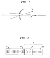
- FIG. 1 illustrates the basic concept of using Fourier spatial filtering to strip away the higher order modes from a propagating signal.
- Light rays incident on a lens 1 with wave vectors at various angles are focused to specific points in the focal plane F of lens 1, these points being related to the angle of the associated wave vector relative to the optical axis OA of lens 1.
- rays with wave vectors parallel to the optical axis such as wave vector A in FIG. 1 focus to a spot on optical axis OA in the focal plane F.
- Rays with wave vector components non-parallel to optical axis OA such as wave vector B in FIG. 1 focus away from optical axis OA in the focal plane F.
- the shift away from the optical axis in the focal plane is larger for waves with a large transverse component of the wavevector.
- the desired wave vector can be chosen for transmission. For example, by placing pinhole P on optical axis OA, wave vector A propagating parallel to optical axis OA will be transmitted while filtering out all other wave vectors (such as wave vector B).
- the fundamental mode of an optical signal propagating through a fiber is known to exhibit the smallest transverse wave vector component, whereas higher order modes have larger transverse wave vector components. Therefore, when the modes from multimode fiber are focused by a lens, the fundamental mode lies in a small area approximately centered on the optical axis in the focal plane, whereas the higher order modes are focused further away from the optical axis. A pinhole placed on the optical axis in the focal plane will therefore transmit only the fundamental mode and eliminate the higher order modes in the transmitted beam.
- FIG. 2 illustrates an exemplary spatial mode filter 10 formed in accordance with an embodiment of the present invention.
- mode filter 10 comprises a section of GRIN fiber 12 coupled to a section of small core fiber 14.
- GRIN fiber 12 functions as a lens and performs the necessary Fourier space filtering while small core fiber 14 provides the pinhole aperture required to block the spatially separated higher order modes and permit transmission of only the fundamental mode.
- Mode filter 10 is used in conjunction with a section of multimode fiber 16 and is preferably directly fused to an endface 17 of multimode fiber 16.
- Multimode fiber 16 may comprise a standard multimode fiber or, alternatively, a large mode area (LMA) fiber.
- LMA large mode area
- LMA fiber For the sake of convenience, fiber 16 will hereinafter be referred to as "LMA fiber", with the understanding that this description also includes “multimode fiber”.
- mode filter 10 functions to direct these higher order modes away from the signal path using Fourier spatial filtering as outlined in the diagram of FIG. 1 .
- LMA fiber 16 has a fundamental mode approximated by a Gaussian beam of waist w 1
- small core fiber 14 has a Gaussian waist of w 2
- the length of GRIN fiber lens 12 is selected so that its focusing parameter g satisfies the beam waist mode conversion from w 1 to w 2 . This ensures that the loss for coupling the fundamental mode into small core fiber 14 is minimized.
- the light launched from LMA fiber 16 is Fourier transformed while propagating through quarter-pitch length GRIN fiber lens 12.
- the Fourier transforming element may take the form of any suitable optical component - for example, a "bulk” (discrete) optical component or a fiber-based optical component. In most embodiments, a fiber-based component is preferred for its low levels of coupling loss.
- these modes are Fourier transformed on their propagation through the GRIN lens.
- the fundamental LP 01 mode shown in FIG. 3(a) retains a Gaussian distribution centered on the optical axis.
- the electric field intensity of the higher order modes become distributed, with a majority of the energy in each mode found in rings surrounding the optical axis - the size of the rings increasing with increasing mode order.
- FIG. 3(b) illustrates the intensity distribution for the LP 02 mode, FIG. 3(c) for the LP 03 mode and FIG. 3(d) for the LP 04 mode.
- FIG. 4 illustrates a normalized electric field intensity for the fundamental LP 01 mode and the next-highest LP 02 mode at both the input and output of an exemplary quarter pitch GRIN lens.
- the graphs in FIG. 4(a) are plots of the electric field intensities at the input to the GRIN lens - illustrating the overlap in modal energies which is present as the signal propagates along an LMA fiber.
- the Fourier transforming properties of the GRIN lens are evident in the plots of FIG. 4(b), where essentially all of the energy associated with the fundamental mode is now concentrated within the central optical axis region of the GRIN lens.
- the Fourier transform of the LP 02 mode results in creating a peak (shown as "A" in FIG. 4(b)) at a location which is spatially separated from the optical axis, with a majority of the energy of this mode residing within this peak area. This distribution confirms the diagram of FIG. 3(b), also associated with the LP 02 mode.
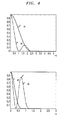
- FIG. 5 is a plot of the fraction of mode energy contained within a given radius as a function of the radial coordinate.
- FIG. 6 shows the calculated coupling loss (in dB) between the various modes of the LMA fiber and the fundamental mode of the small core single mode fiber.
- the fundamental LP 01 mode of the LMA fiber is coupled to the small core single mode fiber with very low loss (approximately 0.15 dB), whereas all higher order modes LP 0m suffer losses exceeding 15 dB.
- LP nm modes where n is non zero, such as the LP 12 , have zero coupling to the fundamental mode in an axis-symmetric geometry because of symmetry considerations).
- the device of the present invention is used to treat a multimode signal propagating along an LMA fiber.
- the pinhole element in conjunction with the GRIN fiber lens, functions to provide the desired spatial mode filtering. In order to prevent nonlinear signal distortion in a small core fiber used as the pinhole element, it is desirable to limit its length as much as possible.
- the maximum length L 1 of this fiber should be limited to less than or equal to: w 1 / w 2 2 ⁇ L 2 , where L 2 is the length of the LMA fiber preceding the GRIN lens, and w 1 and w 2 are the beam waists as defined above.
- L 2 is the length of the LMA fiber preceding the GRIN lens
- w 1 and w 2 are the beam waists as defined above.
- the limit on the length of the small core fiber is also defined by a consideration of the minimum length required to strip away these cladding modes so that they do not appear at the termination of the small core fiber. Obviously, this length will depend upon various parameters of each of the system components. Indeed, the stripping of the cladding modes of the small core fiber could be enhanced by specific fiber design, or by applying high-index gels or polymers to the fiber surface. These and other techniques may be used in conjunction with the arrangement of the present invention to reduce the length of the small core fiber being used as the pinhole element.
- the spatial mode filter of the present invention is particularly well-suited for use in fiber laser and amplifier systems employing LMA fibers.
- An advantage of implementing the spatial mode filter of the present inventions is that it prevents energy stored in the lasing medium from being drained away by the higher order modes which would otherwise continue to propagate within the medium.
- FIG. 7 depicts an exemplary arrangement for using a spatial mode filter within a fiber amplifier system. It is to be understood that only a portion of a complete fiber amplifier is illustrated.
- a first section of LMA fiber 20 provides amplification to a propagating optical signal O.
- LMA fiber 20 includes a rare earth dopant (such as, for example, erbium or ytterbium) for amplifying the propagating optical signal.
- a spatial mode filter 30, similar to spatial mode filter 10 of FIG. 2 is coupled to an endface 22 of first LMA fiber section 20.
- Mode filter 30 includes a GRIN lens 32 (in this example comprising a section of optical fiber and hereinafter referred to as "GRIN fiber lens 32") followed by a small core fiber 34 (used as the pinhole element in the inventive spatial filter).
- GRIN fiber lens 32 functions to Fourier transform the propagating optical signal and spatially shift the propagating higher order modes away from the fiber axis so that they are thereafter blocked from entering small core fiber 34.
- a second GRIN fiber lens 24 is coupled to an output endface 36 of small core fiber 34, thereby preserving the preferred all-fiber configuration.
- GRIN fiber lens 24 functions as a mode converter to increase the spot size of the fundamental mode output by small core fiber 34 in order to match the fundamental mode of second section of LMA fiber 26 (that is, convert the beam waist from w 2 back to the original mode size of w 1 ).
- the second section of LMA fiber 26 can be directly coupled to an endface 25 of second GRIN fiber lens 24.
- the arrangement of FIG. 7 may be repeated along multiple sections of multimode fiber, such as a transmission fiber system, where a second GRIN lens is appended to the output of the each spatial mode filter section to provide mode matching.
- a first GRIN lens/small core fiber/second GRIN lens can be disposed at disparate locations along a multimode transmission fiber to periodically filter out the unwanted higher order modes of the propagating optical signal.
- FIG. 8 One such arrangement using multiple spatial mode filters is illustrated in FIG. 8 .
- a second GRIN lens is used in conjunction with each spatial mode filter to match the mode of the filtered output signal from the small core single mode fiber to the mode of the following section of multimode fiber 50.
- FIG. 9 presents another embodiment of the inventive spatial mode filter, particularly well-suited for use in a fiber laser/amplifier system.
- a reflecting element 60 is coupled to the output of a spatial mode filter 70, spatial mode filter 70 including a GRIN fiber lens 72 and small core single mode fiber 74 as described above.
- Reflecting element 60 can take the form of, for example, a grating structure written into an optical fiber with the period of the grating selected to reflect the wavelength of the propagating, amplified signal.
- the fundamental mode signal Upon reaching reflective element 60, the fundamental mode signal reverses in direction and passes again through small core single mode fiber 74 and GRIN fiber lens 72 (as indicated by the arrows in FIG. 8 ) to re-enter LMA fiber 80.
- GRIN fiber lens 72 By virtue of the reciprocal nature of the mode converting properties of GRIN fiber lens 72, a spot size of the reflected signal is enlarged to substantially match the mode size of LMA fiber 80.
- the reflected, large mode area signal is shown by the dotted line in FIG. 9 .
Landscapes
- Physics & Mathematics (AREA)
- Electromagnetism (AREA)
- Engineering & Computer Science (AREA)
- Computer Networks & Wireless Communication (AREA)
- Signal Processing (AREA)
- Chemical & Material Sciences (AREA)
- Dispersion Chemistry (AREA)
- General Physics & Mathematics (AREA)
- Optics & Photonics (AREA)
- Optical Couplings Of Light Guides (AREA)
- Light Guides In General And Applications Therefor (AREA)
- Optical Fibers, Optical Fiber Cores, And Optical Fiber Bundles (AREA)
- Optical Communication System (AREA)
Abstract
Description
- The present invention relates to a mode filter for removing higher order mode signals propagating along a multimode fiber and, more particularly, to the use of the Fourier transform property of a graded index (GRIN) lens, in combination with a pinhole element, to block further propagation of higher order modes.
- Large mode area (LMA) fibers are widely used in the fabrication of optical fiber-based elements such as high power lasers and amplifiers. The increase in mode area with respect to conventional fibers offer several benefits, such as reduced signal impairment (associated with nonlinearities), increased overlap of a pump signal with the gain medium in an amplifier, and increased energy storage capacity. However, increasing the mode area of these fibers results in them becoming "multi-moded", where multiple spatial modes can be excited through discrete or distributed scattering events along the length of the fiber. These multiple spatial modes interfere with the fundamental signal mode, altering the center of mass position of the beam and increasing the minimum focused spot size (M2). It is therefore desirable to remove the higher order spatial modes present within fiber systems formed of LMA fiber.
- Much of the current research in high power fiber lasers is devoted to engineering complex LMA fiber configurations so that they effectively support only the fundamental mode. The index profile and/or dopant profile of LMA fiber is designed so that the fiber exhibits differential gain for the fundamental mode or, alternatively, differential loss for the higher order modes. Coiling and/or tapering LMA fibers have previously been used to strip away higher order modes. However, tight bending of LMA fiber shifts the mode away from the fiber axis and reduces the mode area, while increasing nonlinearity. The bending also impacts the degree of overlap between the signal and the doped core region of the fiber, thereby reducing gain. Fiber taper lengths are relatively long (e.g., a few centimeters) which results in increased nonlinearity arising from propagation in a small mode area, and the tapered fiber section is fragile and requires special packaging.
- The needs remaining in the prior art are addressed by the present invention, which relates to a mode filter for removing higher order mode signals propagating along a multimode fiber, such as a "large mode area" - LMA - fiber and, more particularly, to the use of the Fourier transform property of a GRIN lens, in combination with a pinhole element, to block the further propagation of higher order modes.
- The GRIN lens may be fiber-based or a bulk optic component. The pinhole element preferably comprises a small core fiber coupled to the output of the GRIN lens to collect only that portion of the optical signal propagating along the optical axis. Since the GRIN lens shifts the higher order modes away from the optical axis, only the fundamental mode of the optical signal will be coupled into the small core fiber. In a preferred embodiment of the inventive spatial mode filter, a fiber-based GRIN lens is used in combination with a small core fiber, thus forming an "in-fiber" mode filter that may be fused to an endface termination of the multimode (LMA) fiber. While this is the preferred embodiment, a bulk optic arrangement using a bulk GRIN lens may also be used to achieve the same mode stripping results.
- In one embodiment, the mode filter of the present invention is disposed at the output of a section of LMA fiber used as a gain medium for a fiber amplifier so as to remove unwanted higher order modes from the amplified signal.
- Another embodiment of the present invention includes a plurality of mode filters distributed in series along a multimode transmission fiber for periodic "cleaning" of an optical signal propagating along the multimode fiber. The deployment of multiple spatial mode filters along a multimode fiber-based communication system functions to periodically remove unwanted higher order mode signals generated during signal propagation along a length of multimode fiber.
- One advantage of an in-fiber embodiment of the present invention is low levels of fundamental mode loss. In a preferred embodiment of the present invention, a GRIN fiber lens is directly fused to the output of the multimode signal fiber (e.g., LMA fiber). When used in conjunction with a fiber amplifier, various other amplifier elements may also be fiber-based (e.g., reflectors, mode converters, and the like) and directly coupled to the inventive mode filter, further reducing levels of insertion loss within the optical system.
- Other and further aspects and embodiments of the present invention will become apparent during the course of the following discussion and by reference to the accompanying drawings.
- Referring now to the drawings,
-
FIG. 1 is a diagram showing the basic concepts of Fourier spatial mode filtering; -
FIG. 2 illustrates an exemplary mode filter formed in accordance with the present invention; -
FIG. 3 is a set of simulated electric field intensities illustrate the Fourier transforming properties of a GRIN optical lens, FIG. 3(a) associated with the fundamental LP01 mode and FIGs. 3(b) - (d) associated with higher order LP0x modes; -
FIG. 4 illustrates the change in field intensity for the fundamental LP01 mode and the higher order LP02 mode, showing the intensity profiles at the input of a GRIN optical lens (FIG. 4(a)) and the output of the GRIN optical lens (FIG. 4(b)); -
FIG. 5 is a plot of the fraction of mode energy contained within a given radius as a function of the radial coordinate for the fundamental mode and a number of higher order modes; -
FIG. 6 shows the calculated coupling loss (in dB) between the various modes of the LMA fiber and the fundamental mode of the small core single mode fiber; -
FIG. 7 illustrates another embodiment of the present invention, in this case utilizing a GRIN mode converter at the output of the spatial mode filter to re-covert the beam waist from the small core single mode fiber to the larger waist associated with a second section of LMA fiber; -
FIG. 8 shows an exemplary optical fiber communication system using spatial mode filtering in accordance with the present invention, showing a series of four separate spatial mode filters disposed along the communication fiber in a spaced-apart arrangement; and -
FIG. 9 illustrates another embodiment of the present invention, well-suited for use in a fiber-based amplifier or laser configuration, incorporating a wavelength selective reflecting element disposed at the output of the spatial mode filter. - The lensing properties of graded index (GRIN) optical elements are well-known in the art. Generally speaking, GRIN optical elements have a radial refractive index distribution as defined by the following relation:

- A Gaussian beam with waist w1 (which is not an eigen mode of the GRIN element) is Fourier transformed into another Gaussian beam of waist w2 on propagation through a GRIN element of quarter pitch length. Propagation through a second quarter pith GRIN element converts the beam waist back to w1 . These periodically occurring beam waists are related by the expression:

In the past, this property of GRIN elements has been used to achieve mode-matched coupling between fibers with different mode areas. In the context of high power LMA fiber laser systems, for example, GRIN lenses have been used to selectively couple light from a small core single mode fiber into the fundamental mode of an LMA fiber for subsequent amplification. - In accordance with the present invention, the Fourier transforming property of GRIN lenses is presently used to implement Fourier space filtering, separating the higher order modes from the desired fundamental mode of a signal propagating along a multimode fiber. The spatial mode filter of the present invention may be coupled to, for example, an endface of an LMA fiber amplifier to prevent further amplification of higher order modes or several filters of the present invention may be periodically disposed along a length of multimode transmission fiber to remove any higher order modes that may appear in a propagating communication signal.
-
FIG. 1 illustrates the basic concept of using Fourier spatial filtering to strip away the higher order modes from a propagating signal. Light rays incident on alens 1 with wave vectors at various angles are focused to specific points in the focal plane F oflens 1, these points being related to the angle of the associated wave vector relative to the optical axis OA oflens 1. As shown, rays with wave vectors parallel to the optical axis such as wave vector A inFIG. 1 focus to a spot on optical axis OA in the focal plane F. Rays with wave vector components non-parallel to optical axis OA such as wave vector B inFIG. 1 focus away from optical axis OA in the focal plane F. The shift away from the optical axis in the focal plane is larger for waves with a large transverse component of the wavevector. By placing a pinhole P in focal plane F, the desired wave vector can be chosen for transmission. For example, by placing pinhole P on optical axis OA, wave vector A propagating parallel to optical axis OA will be transmitted while filtering out all other wave vectors (such as wave vector B). - The fundamental mode of an optical signal propagating through a fiber is known to exhibit the smallest transverse wave vector component, whereas higher order modes have larger transverse wave vector components. Therefore, when the modes from multimode fiber are focused by a lens, the fundamental mode lies in a small area approximately centered on the optical axis in the focal plane, whereas the higher order modes are focused further away from the optical axis. A pinhole placed on the optical axis in the focal plane will therefore transmit only the fundamental mode and eliminate the higher order modes in the transmitted beam.
-
FIG. 2 illustrates an exemplaryspatial mode filter 10 formed in accordance with an embodiment of the present invention. In this embodiment,mode filter 10 comprises a section ofGRIN fiber 12 coupled to a section ofsmall core fiber 14.GRIN fiber 12 functions as a lens and performs the necessary Fourier space filtering whilesmall core fiber 14 provides the pinhole aperture required to block the spatially separated higher order modes and permit transmission of only the fundamental mode.Mode filter 10 is used in conjunction with a section ofmultimode fiber 16 and is preferably directly fused to anendface 17 ofmultimode fiber 16.Multimode fiber 16 may comprise a standard multimode fiber or, alternatively, a large mode area (LMA) fiber. For the sake of convenience,fiber 16 will hereinafter be referred to as "LMA fiber", with the understanding that this description also includes "multimode fiber". For the reasons discussed above, there are many applications where continued propagation of the higher order modes is undesirable. In accordance with the present invention,mode filter 10 functions to direct these higher order modes away from the signal path using Fourier spatial filtering as outlined in the diagram ofFIG. 1 . - Referring to
FIG. 2 ,LMA fiber 16 has a fundamental mode approximated by a Gaussian beam of waist w1, whereassmall core fiber 14 has a Gaussian waist of w2. With reference to the equations outlined above, the length ofGRIN fiber lens 12 is selected so that its focusing parameter g satisfies the beam waist mode conversion from w1 to w2. This ensures that the loss for coupling the fundamental mode intosmall core fiber 14 is minimized. As shown diagrammatically inFIG. 2 , the light launched fromLMA fiber 16 is Fourier transformed while propagating through quarter-pitch lengthGRIN fiber lens 12. Although the embodiment depicted inFIG. 2 describes a spatial mode filter with a "quarter-pitch" length of GRIN fiber, one of ordinary skill will recognize that the scope of the present invention encompasses spatial mode filters utilizing various lengths of GRIN fiber, depending on the Fourier transforming properties desired. In general, the Fourier transforming element may take the form of any suitable optical component - for example, a "bulk" (discrete) optical component or a fiber-based optical component. In most embodiments, a fiber-based component is preferred for its low levels of coupling loss. - Whereas the fundamental LP01 mode is thereafter coupled with low loss into
small core fiber 14, the energy of the higher order modes is displaced away from the fiber axis and, as a result, suffers high coupling loss.Small core fiber 14 functions as a "pinhole" wave vector filter and transmits only the lowest spatial frequencies. - Simulations have been performed which confirm the Fourier transforming properties of a GRIN lens as used in the spatial filter of the present invention. Combining these results with the known overlap of the electric field intensity at the output of the GRIN lens with the fundamental mode of the associated small core single mode fiber, the properties of the mode filtering and coupling loss can be calculated.
-
FIG. 3 illustrates the distribution of the electric field intensities of the various LP0m modes (m=1, 2, 3, 4) at the output plane (i.e., the "focal plane") of the GRIN lens in the spatial filter arrangement of the present invention. As discussed above, these modes are Fourier transformed on their propagation through the GRIN lens. As expected, the fundamental LP01 mode shown in FIG. 3(a) retains a Gaussian distribution centered on the optical axis. In contrast, the electric field intensity of the higher order modes become distributed, with a majority of the energy in each mode found in rings surrounding the optical axis - the size of the rings increasing with increasing mode order. FIG. 3(b) illustrates the intensity distribution for the LP02 mode, FIG. 3(c) for the LP03 mode and FIG. 3(d) for the LP04 mode. -
FIG. 4 illustrates a normalized electric field intensity for the fundamental LP01 mode and the next-highest LP02 mode at both the input and output of an exemplary quarter pitch GRIN lens. The graphs in FIG. 4(a) are plots of the electric field intensities at the input to the GRIN lens - illustrating the overlap in modal energies which is present as the signal propagates along an LMA fiber. The Fourier transforming properties of the GRIN lens are evident in the plots of FIG. 4(b), where essentially all of the energy associated with the fundamental mode is now concentrated within the central optical axis region of the GRIN lens. The Fourier transform of the LP02 mode results in creating a peak (shown as "A" in FIG. 4(b)) at a location which is spatially separated from the optical axis, with a majority of the energy of this mode residing within this peak area. This distribution confirms the diagram of FIG. 3(b), also associated with the LP02 mode. - The data plotted in
FIG. 5 further confirms the electric field intensity results depicted inFIG. 3 , whereFIG. 5 is a plot of the fraction of mode energy contained within a given radius as a function of the radial coordinate. As shown, the Fourier-transformed higher order modes exhibit very little overlap with the core region of the small core single mode fiber.FIG. 6 shows the calculated coupling loss (in dB) between the various modes of the LMA fiber and the fundamental mode of the small core single mode fiber. As shown, the fundamental LP01 mode of the LMA fiber is coupled to the small core single mode fiber with very low loss (approximately 0.15 dB), whereas all higher order modes LP0m suffer losses exceeding 15 dB. (Note that LPnm modes, where n is non zero, such as the LP12, have zero coupling to the fundamental mode in an axis-symmetric geometry because of symmetry considerations). - Many applications exist which require the use of LMA fibers to limit nonlinear signal distortions. Whereas in the prior art a GRIN fiber lens has been used to couple a single mode signal propagating along a small core fiber into a large area fiber in an adiabatic, mode-conserving scheme, the device of the present invention is used to treat a multimode signal propagating along an LMA fiber. The pinhole element, in conjunction with the GRIN fiber lens, functions to provide the desired spatial mode filtering. In order to prevent nonlinear signal distortion in a small core fiber used as the pinhole element, it is desirable to limit its length as much as possible. Indeed, the maximum length L1 of this fiber should be limited to less than or equal to:

- Upon being prevented from further propagation along the signal path of the small core fiber, the higher-order mode signals present at the termination of the GRIN fiber lens will thereafter propagating as cladding modes of the small core fiber. Thus, the limit on the length of the small core fiber is also defined by a consideration of the minimum length required to strip away these cladding modes so that they do not appear at the termination of the small core fiber. Obviously, this length will depend upon various parameters of each of the system components. Indeed, the stripping of the cladding modes of the small core fiber could be enhanced by specific fiber design, or by applying high-index gels or polymers to the fiber surface. These and other techniques may be used in conjunction with the arrangement of the present invention to reduce the length of the small core fiber being used as the pinhole element.
- Moreover, it is known that core imperfections may allow for a fundamental mode propagating along an LMA fiber to differ substantially from the ideal Gaussian shape. It is known from the prior art that the utilization of a GRIN lens will perform beam shaping so as to convert a non-Gaussian beam into the preferred Gaussian form, where this specific type of GRIN lens takes on a more complex configuration, including non-parabolic radial refractive index profiles. It is to be understood that these more complex GRIN lenses may be used in implementations of the present invention where non-Gaussian signal conditions are present.
- As mentioned above, the spatial mode filter of the present invention is particularly well-suited for use in fiber laser and amplifier systems employing LMA fibers. An advantage of implementing the spatial mode filter of the present inventions is that it prevents energy stored in the lasing medium from being drained away by the higher order modes which would otherwise continue to propagate within the medium.
- Another embodiment of the present invention, illustrated in
FIG. 7 , depicts an exemplary arrangement for using a spatial mode filter within a fiber amplifier system. It is to be understood that only a portion of a complete fiber amplifier is illustrated. Referring toFIG. 7 , a first section ofLMA fiber 20 provides amplification to a propagating optical signalO. LMA fiber 20 includes a rare earth dopant (such as, for example, erbium or ytterbium) for amplifying the propagating optical signal. Aspatial mode filter 30, similar tospatial mode filter 10 ofFIG. 2 , is coupled to anendface 22 of firstLMA fiber section 20.Mode filter 30 includes a GRIN lens 32 (in this example comprising a section of optical fiber and hereinafter referred to as "GRIN fiber lens 32") followed by a small core fiber 34 (used as the pinhole element in the inventive spatial filter). As with the above-described embodiment,GRIN fiber lens 32 functions to Fourier transform the propagating optical signal and spatially shift the propagating higher order modes away from the fiber axis so that they are thereafter blocked from enteringsmall core fiber 34. - In order to propagate the amplified, filtered signal into a connecting second section of
LMA fiber 26, a secondGRIN fiber lens 24 is coupled to anoutput endface 36 ofsmall core fiber 34, thereby preserving the preferred all-fiber configuration. In this example,GRIN fiber lens 24 functions as a mode converter to increase the spot size of the fundamental mode output bysmall core fiber 34 in order to match the fundamental mode of second section of LMA fiber 26 (that is, convert the beam waist from w2 back to the original mode size of w1 ). The second section ofLMA fiber 26 can be directly coupled to anendface 25 of secondGRIN fiber lens 24. - In yet another embodiment of the present invention, the arrangement of
FIG. 7 may be repeated along multiple sections of multimode fiber, such as a transmission fiber system, where a second GRIN lens is appended to the output of the each spatial mode filter section to provide mode matching. Indeed, repetitive arrangements of a first GRIN lens/small core fiber/second GRIN lens can be disposed at disparate locations along a multimode transmission fiber to periodically filter out the unwanted higher order modes of the propagating optical signal. - One such arrangement using multiple spatial mode filters is illustrated in
FIG. 8 . As shown, an arrangement of a plurality of spatial mode filters 40-1, 40-2, 40-3 and 40-4, formed in accordance with the present invention, are disposed between sections ofmultimode fiber 50, each mode filter comprising a first GRIN lens 42-i (i=1, 2, 3, 4) and a small core fiber 44-i (i=l, 2, 3, 4). A mode converter 46-i (i=l, 2, 3, 4), preferably a second GRIN lens, is used in conjunction with each spatial mode filter to match the mode of the filtered output signal from the small core single mode fiber to the mode of the following section ofmultimode fiber 50. -
FIG. 9 presents another embodiment of the inventive spatial mode filter, particularly well-suited for use in a fiber laser/amplifier system. In this case, a reflectingelement 60 is coupled to the output of aspatial mode filter 70,spatial mode filter 70 including aGRIN fiber lens 72 and small coresingle mode fiber 74 as described above. A section ofLMA fiber 80, incorporating rare-earth dopants to provide amplification to a propagating optical signal, is coupled to the input ofspatial mode filter 70. Reflectingelement 60 can take the form of, for example, a grating structure written into an optical fiber with the period of the grating selected to reflect the wavelength of the propagating, amplified signal. - Upon reaching
reflective element 60, the fundamental mode signal reverses in direction and passes again through small coresingle mode fiber 74 and GRIN fiber lens 72 (as indicated by the arrows inFIG. 8 ) to re-enterLMA fiber 80. By virtue of the reciprocal nature of the mode converting properties ofGRIN fiber lens 72, a spot size of the reflected signal is enlarged to substantially match the mode size ofLMA fiber 80. The reflected, large mode area signal is shown by the dotted line inFIG. 9 . - Although the present invention has been described in terms of the presently preferred embodiments, it is to be understood that such disclosure is not to be interpreted as limited. Various alterations and modifications will no doubt become apparent to those skilled in the art after reading the above disclosure. Accordingly, it is intended that the appended claims be interpreted as covering all such variations as fall within the true spirit and scope of the invention.
Claims (9)
- An optical spatial mode filter for use with multimode input signals including a fundamental mode and at least one higher order mode, the spatial mode filter comprising:a graded index (GRIN) optical lens for receiving a multimode input signal and exhibiting a radial refractive index profile for spatially separating the at least one higher order mode from the fundamental mode of an optical signal propagating along the optical axis thereof; anda pinhole element coupled to the GRIN optical lens, the pinhole element including an aperture disposed to align with the optical axis and sized to permit further propagation of substantially only the fundamental mode of the multimode input signal along the optical axis.
- An optical spatial mode filter as defined in claim 1, wherein the GRIN optical lens comprises a quarter-pitch length L defined as L = π/(2 g), where g is a focusing parameter of the GRIN optical lens.
- An optical spatial mode filter as defined in claim 1, the filter further comprising
a second GRIN optical lens coupled to the output of the pinhole element for increasing a mode area of the propagating fundamental mode optical signal exiting the pinhole element. - An optical spatial mode filter as defmed in claim 1, wherein the pinhole element is configured to support the fundamental mode with a first mode radius w1 and an input multimode signal includes a fundamental mode with a second mode radius w2 and, wherein the first and second mode radii are related by the following expression:

herein λ is a wavelength of the propagating optical signal, n is a refractive index of the GRIN optical lens, and g is a focusing parameter of the GRIN optical lens. - An optical spatial mode filter as defmed in claim 1, wherein the focusing parameter g is associated with a radial distribution of the refractive index n of said GRIN optical lens as follows:

wherein no is associated with the refractive index along the central optical axis, and r is associated with the radial coordinate of the optical element section. - An optical spatial mode filter as defined in claim 1 wherein the GRIN optical lens comprises a refractive index profile for converting a non-Gaussian fundamental mode into a Gaussian output fundamental mode propagating optical signal.
- An optical spatial mode filter as defined in claim 1 wherein the pinhole element comprises a small core fiber.
- An optical spatial mode filter as defined in claim 7 wherein the small core signal mode fiber has a maximum length L1 equal to (w1 /w2 )2 L2 , where L2 is a length of an input multimode fiber coupled to the input of the GRIN fiber lens, w1 is a beamwaist of a multimode signal at the input of the GRIN fiber lens and w2 is a beamwaist of a fundamental mode of an optical signal at the output of the GRIN fiber lens.
- A method of removing higher order modes from an optical signal propagating along a large mode area optical fiber, the method including the steps of:a) applying a multimode optical signal as an input to a GRIN optical lens for spatially separating higher order modes from a fundamental mode propagating along an optical axis; andb) aligning an aperture with the optical axis at the output of the GRIN optical lens, the aperture permitting the further propagation of substantially only the fundamental mode of the optical signal.
Applications Claiming Priority (1)
| Application Number | Priority Date | Filing Date | Title |
|---|---|---|---|
| US12/386,934 US8218928B2 (en) | 2009-04-23 | 2009-04-23 | Spatial filtering of higher order modes in multimode fibers |
Publications (1)
| Publication Number | Publication Date |
|---|---|
| EP2244113A1 true EP2244113A1 (en) | 2010-10-27 |
Family
ID=42111336
Family Applications (1)
| Application Number | Title | Priority Date | Filing Date |
|---|---|---|---|
| EP10156785A Withdrawn EP2244113A1 (en) | 2009-04-23 | 2010-03-17 | Spatial Filtering of Higher Order Modes in Multimode Fibers |
Country Status (5)
| Country | Link |
|---|---|
| US (2) | US8218928B2 (en) |
| EP (1) | EP2244113A1 (en) |
| JP (1) | JP5562106B2 (en) |
| KR (1) | KR101144071B1 (en) |
| CN (1) | CN101893739B (en) |
Cited By (1)
| Publication number | Priority date | Publication date | Assignee | Title |
|---|---|---|---|---|
| EP2533435A1 (en) * | 2011-06-06 | 2012-12-12 | Alcatel Lucent | Spatial mode gain equalization |
Families Citing this family (28)
| Publication number | Priority date | Publication date | Assignee | Title |
|---|---|---|---|---|
| US9563011B2 (en) * | 2010-01-27 | 2017-02-07 | University Of Central Florida Research Foundation, Inc. | Optical transmission using few-mode fibers |
| US20130044978A1 (en) * | 2011-08-20 | 2013-02-21 | Peter DeDobbelaere | Method And System For A Multi-Core Fiber Connector |
| US9417390B2 (en) | 2011-08-31 | 2016-08-16 | Hewlett Packard Enterprise Development Lp | Multimode fiber for modulatable source |
| US8761217B2 (en) | 2012-04-06 | 2014-06-24 | Hewlett-Packard Development Company, L.P. | Modal filters for modulatable sources |
| US9323014B2 (en) | 2012-05-28 | 2016-04-26 | Mellanox Technologies Ltd. | High-speed optical module with flexible printed circuit board |
| US20140301707A1 (en) * | 2013-04-09 | 2014-10-09 | Institut National D'optique | Optical waveguide, mode scrambler and mode conditioner for controlling mode power distribution |
| US20150010267A1 (en) * | 2013-07-04 | 2015-01-08 | Mellanox Technologies Ltd. | Interconnection between silicon photonics devices and optical fibers |
| US20150010268A1 (en) * | 2013-07-04 | 2015-01-08 | Mellanox Technologies Ltd. | Polymer-based interconnection between silicon photonics devices and optical fibers |
| TWI510005B (en) * | 2013-09-12 | 2015-11-21 | Nat Univ Tsing Hua | Device of passive optical repeater used in multimode optical communication |
| WO2015108529A1 (en) * | 2014-01-17 | 2015-07-23 | Empire Technology Development Llc | Optical fibers without cladding |
| US9431788B2 (en) | 2014-04-21 | 2016-08-30 | Ofs Fitel, Llc | Mode converter for high power, higher-order mode optical fiber amplifiers |
| CN107003474A (en) * | 2014-10-23 | 2017-08-01 | 科拉克蒂夫高科技公司 | With beam shaping component, fiber component |
| KR20240064049A (en) | 2014-12-18 | 2024-05-10 | 엔케이티 포토닉스 에이/에스 | A photonic crystal fiber, a method of production thereof and a supercontinuum light source |
| JP5928570B1 (en) * | 2014-12-22 | 2016-06-01 | 東洋製罐グループホールディングス株式会社 | Optical coupler and optical coupling method for optical fiber with GRIN lens |
| US10730785B2 (en) * | 2016-09-29 | 2020-08-04 | Nlight, Inc. | Optical fiber bending mechanisms |
| JP2018194723A (en) * | 2017-05-19 | 2018-12-06 | 矢崎総業株式会社 | Optical connector |
| FR3069070A1 (en) * | 2017-07-17 | 2019-01-18 | Commissariat A L'energie Atomique Et Aux Energies Alternatives | OPTICAL FOCUSING DEVICE WITH INDEX PSEUDO GRADIENT |
| CN107515446B (en) * | 2017-09-14 | 2024-04-26 | 浙江大学 | Method for expanding focal depth based on optical fiber type pupil filter and probe |
| TWI827565B (en) | 2017-11-17 | 2024-01-01 | 立陶宛商布羅利思半導體有限責任公司 | Radiant beam combining of multiple multimode semiconductor laser diodes for directional laser beam delivery applications, and methods for achieving and applying the same |
| CN108267231A (en) * | 2018-03-19 | 2018-07-10 | 浙江师范大学 | High-capacity optical fiber laser power and SBS threshold on-Line Monitor Device |
| WO2020086161A1 (en) | 2018-09-04 | 2020-04-30 | Panduit Corp. | Smf to mmf coupler |
| US11360269B2 (en) * | 2019-03-04 | 2022-06-14 | Lumentum Operations Llc | High-power all fiber telescope |
| CN110320663B (en) * | 2019-03-20 | 2020-12-01 | 华中科技大学 | Ultra-small-size large-bandwidth mode filter designed based on direct binary search algorithm |
| JP2020201420A (en) * | 2019-06-12 | 2020-12-17 | 株式会社フジクラ | Light guiding member and laser device |
| CN110411489B (en) * | 2019-07-16 | 2024-01-30 | 武汉理工大学 | Mode control device for enhancing interference spectrum of sapphire optical fiber FP sensor |
| CN110411488A (en) * | 2019-07-16 | 2019-11-05 | 武汉理工大学 | Sapphire fiber FP sensor interferometer composes the Pattern Filter device of visibility enhancing |
| CN110558958B (en) * | 2019-08-21 | 2022-07-01 | 武汉凯锐普信息技术有限公司 | Vital sign monitoring devices based on light wave mode selection |
| CN110595517A (en) * | 2019-09-23 | 2019-12-20 | 武汉理工大学 | Sapphire optical fiber Fabry-Perot sensor measuring system with enhanced interference spectrum |
Citations (5)
| Publication number | Priority date | Publication date | Assignee | Title |
|---|---|---|---|---|
| WO1988009944A2 (en) | 1987-06-03 | 1988-12-15 | Hughes Aircraft Company | Fiber optic bimodal receiver |
| EP0316191A2 (en) | 1987-11-12 | 1989-05-17 | Raychem Corporation | Dynamic range reduction using mode filter |
| US5003623A (en) | 1983-06-16 | 1991-03-26 | Trw Inc. | Bimodal intrusion detection in an optical fiber communication system using graded index fiber |
| US20060182388A1 (en) * | 2005-02-11 | 2006-08-17 | Shrenik Deliwala | High bit rate optical communication over multimode fibers |
| US20070081764A1 (en) | 2004-11-15 | 2007-04-12 | Shrenik Deliwala | High bitrate transport over multimode fibers |
Family Cites Families (35)
| Publication number | Priority date | Publication date | Assignee | Title |
|---|---|---|---|---|
| US4381137A (en) * | 1981-03-05 | 1983-04-26 | Hydroacoustics Inc. | Optical fiber mode separation systems |
| US4701011A (en) | 1985-01-15 | 1987-10-20 | American Telephone And Telegraph Company, At&T Bell Laboratories | Multimode fiber-lens optical coupler |
| CN1100273C (en) * | 1996-07-31 | 2003-01-29 | 康宁股份有限公司 | Dispersion compensating single mode waveguide |
| US5818630A (en) * | 1997-06-25 | 1998-10-06 | Imra America, Inc. | Single-mode amplifiers and compressors based on multi-mode fibers |
| US6278816B1 (en) | 1997-12-09 | 2001-08-21 | Scientific-Atlanta, Inc. | Noise reduction technique for cladding pumped optical amplifiers |
| US6249626B1 (en) * | 1998-03-06 | 2001-06-19 | Lucent Technologies, Inc. | Multimode fiber optical power monitoring tap for optical transmission systems |
| US6404951B2 (en) * | 1998-03-26 | 2002-06-11 | Lasercomm Inc. | Transverse spatial mode transformer for optical communication |
| US6275512B1 (en) * | 1998-11-25 | 2001-08-14 | Imra America, Inc. | Mode-locked multimode fiber laser pulse source |
| JP3948598B2 (en) | 2000-09-01 | 2007-07-25 | 富士通株式会社 | Method, apparatus and system for processing optical signals |
| US6542665B2 (en) | 2001-02-17 | 2003-04-01 | Lucent Technologies Inc. | GRIN fiber lenses |
| US20020150333A1 (en) * | 2001-02-17 | 2002-10-17 | Reed William Alfred | Fiber devices using grin fiber lenses |
| US6552298B1 (en) | 2001-09-28 | 2003-04-22 | Corning Incorporated | Apparatus and method for making a lens on the end of an optical waveguide fiber |
| US6717721B2 (en) * | 2001-12-21 | 2004-04-06 | Corning Incorporated | Large effective area erbium doped fiber optical amplifier |
| JP2004177817A (en) | 2002-11-28 | 2004-06-24 | Sumitomo Electric Ind Ltd | Optical fiber and optical module |
| JP4107072B2 (en) | 2002-11-29 | 2008-06-25 | 住友電気工業株式会社 | Optical module and optical transmission system |
| US6970624B2 (en) | 2003-06-13 | 2005-11-29 | Furukawa Electric North America | Cladding pumped optical fiber gain devices |
| US6856737B1 (en) | 2003-08-27 | 2005-02-15 | Mesophotonics Limited | Nonlinear optical device |
| GB0327661D0 (en) * | 2003-11-28 | 2003-12-31 | Qinetiq Ltd | Optical Amplifier |
| US6990270B2 (en) | 2004-02-11 | 2006-01-24 | Fitel U.S.A. Corp. | Fiber amplifier for generating femtosecond pulses in single mode fiber |
| US7184623B2 (en) * | 2004-05-25 | 2007-02-27 | Avanex Corporation | Apparatus, system and method for an adiabatic coupler for multi-mode fiber-optic transmission systems |
| FR2875016B1 (en) | 2004-09-08 | 2006-11-24 | Cit Alcatel | MODE CONVERTER |
| US7430224B2 (en) | 2005-08-29 | 2008-09-30 | Polaronyx, Inc. | Automatic dispersion compensation in amplification for short pulse fiber laser system |
| US7400807B2 (en) | 2005-11-03 | 2008-07-15 | Aculight Corporation | Apparatus and method for a waveguide with an index profile manifesting a central dip for better energy extraction |
| US7308171B2 (en) | 2005-11-16 | 2007-12-11 | Raydiance, Inc. | Method and apparatus for optical isolation in high power fiber-optic systems |
| US20070140634A1 (en) | 2005-12-16 | 2007-06-21 | Robert Scott Windeler | Gain-producing, large-mode-area, multimode, hybrid optical fibers and devices using same |
| US7306376B2 (en) | 2006-01-23 | 2007-12-11 | Electro-Optics Technology, Inc. | Monolithic mode stripping fiber ferrule/collimator and method of making same |
| US20070206910A1 (en) | 2006-03-04 | 2007-09-06 | Siddharth Ramachandran | Optical fibers and optical fiber devices with total dispersion greater than material dispersion |
| US7430226B2 (en) | 2006-03-06 | 2008-09-30 | Polar Onyx, Inc. | Dispersion managed fiber stretcher for high-energy short pulse femotosecond fiber laser system |
| US7835608B2 (en) | 2006-03-21 | 2010-11-16 | Lockheed Martin Corporation | Method and apparatus for optical delivery fiber having cladding with absorbing regions |
| US7257293B1 (en) | 2006-07-14 | 2007-08-14 | Furukawa Electric North America, Inc. | Fiber structure with improved bend resistance |
| US7340138B1 (en) * | 2007-01-25 | 2008-03-04 | Furukawa Electric North America, Inc. | Optical fiber devices and methods for interconnecting dissimilar fibers |
| US7916386B2 (en) * | 2007-01-26 | 2011-03-29 | Ofs Fitel, Llc | High power optical apparatus employing large-mode-area, multimode, gain-producing optical fibers |
| US7437046B2 (en) | 2007-02-12 | 2008-10-14 | Furukawa Electric North America, Inc. | Optical fiber configuration for dissipating stray light |
| US7844146B2 (en) * | 2008-04-30 | 2010-11-30 | Ofs Fitel, Llc | All-fiber module for femtosecond pulse compression and supercontinuum generation |
| JP2010199563A (en) * | 2009-01-27 | 2010-09-09 | Fujikura Ltd | Optical amplifier and resonator |
-
2009
- 2009-04-23 US US12/386,934 patent/US8218928B2/en active Active
-
2010
- 2010-03-17 EP EP10156785A patent/EP2244113A1/en not_active Withdrawn
- 2010-04-16 KR KR1020100035133A patent/KR101144071B1/en active IP Right Grant
- 2010-04-22 CN CN201010167136.3A patent/CN101893739B/en active Active
- 2010-04-23 JP JP2010099324A patent/JP5562106B2/en active Active
-
2012
- 2012-05-30 US US13/483,524 patent/US8909017B2/en active Active
Patent Citations (5)
| Publication number | Priority date | Publication date | Assignee | Title |
|---|---|---|---|---|
| US5003623A (en) | 1983-06-16 | 1991-03-26 | Trw Inc. | Bimodal intrusion detection in an optical fiber communication system using graded index fiber |
| WO1988009944A2 (en) | 1987-06-03 | 1988-12-15 | Hughes Aircraft Company | Fiber optic bimodal receiver |
| EP0316191A2 (en) | 1987-11-12 | 1989-05-17 | Raychem Corporation | Dynamic range reduction using mode filter |
| US20070081764A1 (en) | 2004-11-15 | 2007-04-12 | Shrenik Deliwala | High bitrate transport over multimode fibers |
| US20060182388A1 (en) * | 2005-02-11 | 2006-08-17 | Shrenik Deliwala | High bit rate optical communication over multimode fibers |
Cited By (1)
| Publication number | Priority date | Publication date | Assignee | Title |
|---|---|---|---|---|
| EP2533435A1 (en) * | 2011-06-06 | 2012-12-12 | Alcatel Lucent | Spatial mode gain equalization |
Also Published As
| Publication number | Publication date |
|---|---|
| JP5562106B2 (en) | 2014-07-30 |
| US20120237164A1 (en) | 2012-09-20 |
| US8218928B2 (en) | 2012-07-10 |
| CN101893739A (en) | 2010-11-24 |
| KR101144071B1 (en) | 2012-05-23 |
| US20100271689A1 (en) | 2010-10-28 |
| KR20100117027A (en) | 2010-11-02 |
| US8909017B2 (en) | 2014-12-09 |
| CN101893739B (en) | 2014-07-16 |
| JP2010256905A (en) | 2010-11-11 |
Similar Documents
| Publication | Publication Date | Title |
|---|---|---|
| US8218928B2 (en) | Spatial filtering of higher order modes in multimode fibers | |
| JP3987840B2 (en) | Cladding pump optical fiber gain device | |
| US7272288B2 (en) | Large mode area fibers using higher order modes | |
| JP5827949B2 (en) | Multimode fiber | |
| US8094370B2 (en) | Cladding pumped fibre laser with a high degree of pump isolation | |
| EP1213802A2 (en) | Optical fiber amplifiers and lasers and optical pumping devices therefore and methods of fabricating the same | |
| US6433927B1 (en) | Low cost amplifier using bulk optics | |
| JP2020144186A (en) | Optical connection structure | |
| CN101512851B (en) | Fiber optic power laser device | |
| EP1858128B1 (en) | Large mode area fibers by using conversion to higher order modes | |
| JP6203779B2 (en) | Mode converter for high power, higher order mode optical fiber amplifier | |
| US20240266796A1 (en) | Super-mode selective optical unit | |
| DiGiovanni et al. | Progress in all-fiber components | |
| CN104917040B (en) | A kind of annular multi-wavelength light fiber amplifier | |
| Ramachandran et al. | Robust light propagation in ultra-large mode-area fibers |
Legal Events
| Date | Code | Title | Description |
|---|---|---|---|
| PUAI | Public reference made under article 153(3) epc to a published international application that has entered the european phase |
Free format text: ORIGINAL CODE: 0009012 |
|
| 17P | Request for examination filed |
Effective date: 20100831 |
|
| AK | Designated contracting states |
Kind code of ref document: A1 Designated state(s): AT BE BG CH CY CZ DE DK EE ES FI FR GB GR HR HU IE IS IT LI LT LU LV MC MK MT NL NO PL PT RO SE SI SK SM TR |
|
| AX | Request for extension of the european patent |
Extension state: AL BA ME RS |
|
| STAA | Information on the status of an ep patent application or granted ep patent |
Free format text: STATUS: EXAMINATION IS IN PROGRESS |
|
| 17Q | First examination report despatched |
Effective date: 20180323 |
|
| STAA | Information on the status of an ep patent application or granted ep patent |
Free format text: STATUS: EXAMINATION IS IN PROGRESS |
|
| RIC1 | Information provided on ipc code assigned before grant |
Ipc: H04B 10/2581 20130101ALI20201109BHEP Ipc: G02B 6/028 20060101AFI20201109BHEP |
|
| STAA | Information on the status of an ep patent application or granted ep patent |
Free format text: STATUS: EXAMINATION IS IN PROGRESS |
|
| STAA | Information on the status of an ep patent application or granted ep patent |
Free format text: STATUS: THE APPLICATION IS DEEMED TO BE WITHDRAWN |
|
| 18D | Application deemed to be withdrawn |
Effective date: 20221001 |