EP2244035A1 - Carrier device for solar panels - Google Patents
Carrier device for solar panels Download PDFInfo
- Publication number
- EP2244035A1 EP2244035A1 EP10160814A EP10160814A EP2244035A1 EP 2244035 A1 EP2244035 A1 EP 2244035A1 EP 10160814 A EP10160814 A EP 10160814A EP 10160814 A EP10160814 A EP 10160814A EP 2244035 A1 EP2244035 A1 EP 2244035A1
- Authority
- EP
- European Patent Office
- Prior art keywords
- longitudinal
- runners
- junction point
- runner
- fastened
- Prior art date
- Legal status (The legal status is an assumption and is not a legal conclusion. Google has not performed a legal analysis and makes no representation as to the accuracy of the status listed.)
- Withdrawn
Links
- 238000010276 construction Methods 0.000 claims abstract description 17
- 230000005855 radiation Effects 0.000 claims abstract description 7
- 239000000969 carrier Substances 0.000 description 6
- 239000000758 substrate Substances 0.000 description 2
- 230000001154 acute effect Effects 0.000 description 1
- 238000005516 engineering process Methods 0.000 description 1
- 239000000463 material Substances 0.000 description 1
- 229920003023 plastic Polymers 0.000 description 1
- 239000004033 plastic Substances 0.000 description 1
- XLYOFNOQVPJJNP-UHFFFAOYSA-N water Substances O XLYOFNOQVPJJNP-UHFFFAOYSA-N 0.000 description 1
- 238000003466 welding Methods 0.000 description 1
Images


Classifications
-
- H—ELECTRICITY
- H02—GENERATION; CONVERSION OR DISTRIBUTION OF ELECTRIC POWER
- H02S—GENERATION OF ELECTRIC POWER BY CONVERSION OF INFRARED RADIATION, VISIBLE LIGHT OR ULTRAVIOLET LIGHT, e.g. USING PHOTOVOLTAIC [PV] MODULES
- H02S20/00—Supporting structures for PV modules
- H02S20/10—Supporting structures directly fixed to the ground
-
- F—MECHANICAL ENGINEERING; LIGHTING; HEATING; WEAPONS; BLASTING
- F24—HEATING; RANGES; VENTILATING
- F24S—SOLAR HEAT COLLECTORS; SOLAR HEAT SYSTEMS
- F24S30/00—Arrangements for moving or orienting solar heat collector modules
- F24S30/40—Arrangements for moving or orienting solar heat collector modules for rotary movement
- F24S30/42—Arrangements for moving or orienting solar heat collector modules for rotary movement with only one rotation axis
- F24S30/428—Arrangements for moving or orienting solar heat collector modules for rotary movement with only one rotation axis with inclined axis
-
- H—ELECTRICITY
- H02—GENERATION; CONVERSION OR DISTRIBUTION OF ELECTRIC POWER
- H02S—GENERATION OF ELECTRIC POWER BY CONVERSION OF INFRARED RADIATION, VISIBLE LIGHT OR ULTRAVIOLET LIGHT, e.g. USING PHOTOVOLTAIC [PV] MODULES
- H02S20/00—Supporting structures for PV modules
- H02S20/20—Supporting structures directly fixed to an immovable object
- H02S20/22—Supporting structures directly fixed to an immovable object specially adapted for buildings
- H02S20/23—Supporting structures directly fixed to an immovable object specially adapted for buildings specially adapted for roof structures
-
- H—ELECTRICITY
- H02—GENERATION; CONVERSION OR DISTRIBUTION OF ELECTRIC POWER
- H02S—GENERATION OF ELECTRIC POWER BY CONVERSION OF INFRARED RADIATION, VISIBLE LIGHT OR ULTRAVIOLET LIGHT, e.g. USING PHOTOVOLTAIC [PV] MODULES
- H02S20/00—Supporting structures for PV modules
- H02S20/30—Supporting structures being movable or adjustable, e.g. for angle adjustment
-
- F—MECHANICAL ENGINEERING; LIGHTING; HEATING; WEAPONS; BLASTING
- F24—HEATING; RANGES; VENTILATING
- F24S—SOLAR HEAT COLLECTORS; SOLAR HEAT SYSTEMS
- F24S30/00—Arrangements for moving or orienting solar heat collector modules
- F24S2030/10—Special components
- F24S2030/13—Transmissions
- F24S2030/131—Transmissions in the form of articulated bars
-
- F—MECHANICAL ENGINEERING; LIGHTING; HEATING; WEAPONS; BLASTING
- F24—HEATING; RANGES; VENTILATING
- F24S—SOLAR HEAT COLLECTORS; SOLAR HEAT SYSTEMS
- F24S30/00—Arrangements for moving or orienting solar heat collector modules
- F24S2030/10—Special components
- F24S2030/13—Transmissions
- F24S2030/136—Transmissions for moving several solar collectors by common transmission elements
-
- F—MECHANICAL ENGINEERING; LIGHTING; HEATING; WEAPONS; BLASTING
- F24—HEATING; RANGES; VENTILATING
- F24S—SOLAR HEAT COLLECTORS; SOLAR HEAT SYSTEMS
- F24S25/00—Arrangement of stationary mountings or supports for solar heat collector modules
- F24S25/10—Arrangement of stationary mountings or supports for solar heat collector modules extending in directions away from a supporting surface
- F24S25/13—Profile arrangements, e.g. trusses
-
- Y—GENERAL TAGGING OF NEW TECHNOLOGICAL DEVELOPMENTS; GENERAL TAGGING OF CROSS-SECTIONAL TECHNOLOGIES SPANNING OVER SEVERAL SECTIONS OF THE IPC; TECHNICAL SUBJECTS COVERED BY FORMER USPC CROSS-REFERENCE ART COLLECTIONS [XRACs] AND DIGESTS
- Y02—TECHNOLOGIES OR APPLICATIONS FOR MITIGATION OR ADAPTATION AGAINST CLIMATE CHANGE
- Y02B—CLIMATE CHANGE MITIGATION TECHNOLOGIES RELATED TO BUILDINGS, e.g. HOUSING, HOUSE APPLIANCES OR RELATED END-USER APPLICATIONS
- Y02B10/00—Integration of renewable energy sources in buildings
- Y02B10/10—Photovoltaic [PV]
-
- Y—GENERAL TAGGING OF NEW TECHNOLOGICAL DEVELOPMENTS; GENERAL TAGGING OF CROSS-SECTIONAL TECHNOLOGIES SPANNING OVER SEVERAL SECTIONS OF THE IPC; TECHNICAL SUBJECTS COVERED BY FORMER USPC CROSS-REFERENCE ART COLLECTIONS [XRACs] AND DIGESTS
- Y02—TECHNOLOGIES OR APPLICATIONS FOR MITIGATION OR ADAPTATION AGAINST CLIMATE CHANGE
- Y02E—REDUCTION OF GREENHOUSE GAS [GHG] EMISSIONS, RELATED TO ENERGY GENERATION, TRANSMISSION OR DISTRIBUTION
- Y02E10/00—Energy generation through renewable energy sources
- Y02E10/40—Solar thermal energy, e.g. solar towers
- Y02E10/47—Mountings or tracking
-
- Y—GENERAL TAGGING OF NEW TECHNOLOGICAL DEVELOPMENTS; GENERAL TAGGING OF CROSS-SECTIONAL TECHNOLOGIES SPANNING OVER SEVERAL SECTIONS OF THE IPC; TECHNICAL SUBJECTS COVERED BY FORMER USPC CROSS-REFERENCE ART COLLECTIONS [XRACs] AND DIGESTS
- Y02—TECHNOLOGIES OR APPLICATIONS FOR MITIGATION OR ADAPTATION AGAINST CLIMATE CHANGE
- Y02E—REDUCTION OF GREENHOUSE GAS [GHG] EMISSIONS, RELATED TO ENERGY GENERATION, TRANSMISSION OR DISTRIBUTION
- Y02E10/00—Energy generation through renewable energy sources
- Y02E10/50—Photovoltaic [PV] energy
Definitions
- the invention relates to a carrier device for elements intended for absorbing and/or reflecting and/or focusing solar radiation, such as solar cells, solar collectors, mirrors, lenses and the like, comprising a main frame made up of longitudinal runners extending parallel next to one another and cross runners extending transversely to the longitudinal runners, auxiliary frames, which are rotatably attached to the main frame, for the elements, and also a support construction acting on two of the horizontal runners.
- a carrier device of this type is generally known.
- the longitudinal runners can be placed at a height such that the elements are optimally directed for as long a period as possible with respect to the sun in order to catch as much energy as possible. In this regard, account is taken of the average local position of the sun over the course of a year.
- the energy originating from the sun can be converted into electric power on use of photovoltaic solar cells. It is also possible to heat water by means of solar collectors. It is also known to reflect sunlight to a central unit by means of a number of mirrors, likewise for generating electric power or heat.
- the support devices are usually used outdoors, meaning that they must be sufficiently strong and rigid to withstand loads by the wind, snow and the like. Because the panels can take up large surface areas, the mechanical properties of the support device must satisfy stringent requirements.
- the known devices are therefore equipped with heavy constructional components which must be able to transmit the loads generated by wind and snow and the like to the substrate without much deformation of the construction. That is to say, for an acceptable output of the device, it is very important that the desired orientation of the panels with respect to the sun can still be maintained even under high loads. On the other hand, it is desirable to keep the investment in support constructions within a reasonable scale, so that competition with traditional forms of energy generation remains possible.
- the object of the invention is therefore to provide a device of the type mentioned hereinbefore for supporting solar panels and the like that is more satisfactory both from the point of view of constructional technology and from an economic point of view. That object is achieved in that universal junction points are provided, to each of which a longitudinal runner and an auxiliary frame are fastened. Preferably, substantially all the connections between a longitudinal runner and a cross runner are formed by universal and identical junction points of this type. Furthermore, struts extending obliquely between the longitudinal runners can be fastened to the junction points in connection with increasing the shear rigidity of the main frame.
- junction points can be embodied in many different ways. However, for all the variants, it is the case that the various carrying parts of the device meet at said junction points.
- the longitudinal runners and the cross runners can be securely fastened to one another so as to produce a rigid overall entity which can hold the auxiliary frames with the elements stably in the desired position.
- the parts of the support construction that are located there can act on the longitudinal runners by means of the junction points.
- the cross runners can comprise hollow rods, the ends of which may be formed by oblate fastening lips, which fastening lips are each connected to a junction point.
- the junction points can each comprise one or more fastening flanges, a cross runner being fastened to the fastening flange of at least one of the junction points.
- a particularly stable construction is obtained if the junction points each comprise two fastening flanges located on either side of the longitudinal runner, a cross runner being fastened to the fastening flanges of at least one of the junction points.
- separate fastening fittings which can for example be secured to the ends of the rods by welding, clamping and the like, can also be provided at the ends of the rods.
- junction points can each comprise a support flange which is fastened to the support construction.
- This support construction which extends spread out substantially over the entire length of the longitudinal runners, can also be embodied in many different ways.
- the support construction can comprise legs or rods, an end of which is fastened in each case to a junction point. These rods are preferably hollow and can have a circular cross section. These rods can be pinched flat at their ends, so that fastening lips are obtained there.
- separate fastening fittings can be provided at the ends of the rods. The rods can be fastened to the fastening flanges of the junction points by means of the fastening lips.
- the other end of the rods can be supported on a foundation, such as a base.
- a foundation such as a base.
- a particularly stable support is obtained if one or more of the rods form an acute or oblique angle with the longitudinal direction of the longitudinal runners.
- An example of this is an embodiment wherein in each case at least two rods converge from the main frame and are supported on one and the same foundation.
- each junction point serves not only to join together the components of the frame but are also involved, as mentioned hereinbefore, in the fastening and supporting of the auxiliary frames and the panels.
- each junction point can in this case be provided with a bracket to which an auxiliary frame is fastened.
- the auxiliary frames come to lie at a certain distance above the main frame by means of brackets of this type. This has the advantage that the auxiliary frames can be placed in a simple manner in an oblique position with respect to the frame, depending on the position of the sun.
- the auxiliary frames can in that connection be rotatable about an axis which is parallel to the cross runners.
- a bearing block may be located on each bracket, whereas the auxiliary frames each contain a carrier which is rotatably supported in the bearing block of a junction point provided on a longitudinal runner and the opposing bearing block of a junction point provided on the other longitudinal runner.
- the bearing portion of these bearing blocks can be embodied in many different ways. An example of this is a slide bearing with a plastics material shell in which a cylindrical carrier is rotatably supported.
- the carriers can each be provided with mutually parallel arms which are distributed over the length of the carrier and to which a panel is fastened.
- junction points themselves can also be embodied in many different ways.
- the junction points can consist of a single entity, and be slid on or around the longitudinal runners.
- each junction point comprises two fitting pieces, between each of which a longitudinal runner is clamped.
- These associated fitting pieces can be securely clamped to or around the longitudinal runner parts in question by means of suitable bolt connections.
- the mutually facing surfaces of in each case a fitting piece and a longitudinal runner can be shaped in a corresponding manner.
- the fitting pieces can be joined together to form a single entity by means of an intervening dam, in such a way that a C shape is produced.
- the invention further relates to an arrangement for generating energy from solar radiation, comprising a carrier device as described hereinbefore with a main frame made up of longitudinal runners extending parallel next to one another, cross runners extending transversely to the longitudinal runners, auxiliary frames which are rotatably attached to the main frame, and also a support construction acting on the main frame, the auxiliary frames being provided with elements intended for absorbing or reflecting solar radiation, such as solar cells, solar collectors, mirrors and the like.
- the invention relates to a universal junction point for the carrier device as described hereinbefore.
- the device represented in Figures 1-4 has a main frame 1 consisting of the longitudinal runners 2 and the cross runners 3 which join the longitudinal runners together. Furthermore, the strut 14 is fastened to the longitudinal runners 2. This strut 14 is directed obliquely, in such a way that the main frame 1 is shear rigid in the plane defined by the longitudinal and cross runners.
- the auxiliary frames 5 are supported in the bearing blocks 24 with rotary bearings 6, as shown in Figures 5 and 6 .
- These auxiliary frames each consist of a carrier 7 with arms 8 attached thereto so as to be spread out in a uniform manner.
- the panels 9, in this case with photovoltaic cells, are fastened to these arms.
- the auxiliary frames 5 with the panels can be rotated in an oblique position, about the axis of the carriers 7, depending on the position of the sun, by means of the adjusting device, the adjusting rod 10 of which is represented in Figures 1-3 .
- the main frame 1 is supported on a substrate by means of the bases 11.
- the lower longitudinal runner 2 is directly supported on the bases 11 via junction points 4 to be described in greater detail.
- the upper longitudinal runner 2 is supported by means of the rods 12 and 13. In the rear view of Figure 3 , some of these rods 13 are directed perpendicularly to the longitudinal runners 2, other rods 12 diverge obliquely.
- the rods 12-14 have oblate fastening lips 23 at both ends.
- Each of the rods 13 is fastened to the upper longitudinal runner 2 by a junction point 4, as is represented on a larger scale in Figures 5 and 6 .
- These junction points each consist of two fitting pieces 15, 16, between which a longitudinal runner 2 is clamped by means of a bolt connection 17.
- the fitting pieces have ledges 18 between which the longitudinal runner 2, which is embodied as a C-shaped profile, is trapped. Furthermore, they have fastening flanges 19, to each of which an oblate fastening lip 23 of the rods 20 is fastened.
- These two rods 20 together form the cross runner 3.
- the bottom fitting piece 16 also has a support flange 21 to which the fastening lip 23 of the rod 13 is fastened.
- the top fitting piece 15 has an upright bracket 22 to which the rotary bearing 6 is fitted.
- the carriers 7, and thus the auxiliary frames 5 with the panels 9, are therefore fitted at a certain height above the main frame 1, in such a way that rotations thereof about the axis of the carriers 7 are possible.
- the lower longitudinal runner 2 is also supported on a base 11 by a junction point 4 of this type, the support flange 21 then being fastened directly thereto without the intervention of a rod. Furthermore, the bottom ends of the obliquely upwardly diverging rods 12 are fastened to said junction points 4. The bottom end of the obliquely positioned strut 14 is also fastened to one of said junction points.
- connection between the longitudinal runners 2 and the carriers 7 is embodied in all cases with junction points 4 of this type.
- the fastening flanges 19 remain unused because the cross runners 3 or rods 20 are omitted there.
- the support flanges 21 are not used in all cases either: some of the junction points 4 on the lower longitudinal runner 2 function merely as a connection between the carriers 7 and the longitudinal runner 2. Nevertheless, one and the same junction point 4 can be used in all cases for each connection between the main frame 1, auxiliary frames 5 and rods 12, 13, 14 and 20; this greatly simplifies the construction and makes it more economical.
Abstract
Description
- The invention relates to a carrier device for elements intended for absorbing and/or reflecting and/or focusing solar radiation, such as solar cells, solar collectors, mirrors, lenses and the like, comprising a main frame made up of longitudinal runners extending parallel next to one another and cross runners extending transversely to the longitudinal runners, auxiliary frames, which are rotatably attached to the main frame, for the elements, and also a support construction acting on two of the horizontal runners.
- A carrier device of this type is generally known. The longitudinal runners can be placed at a height such that the elements are optimally directed for as long a period as possible with respect to the sun in order to catch as much energy as possible. In this regard, account is taken of the average local position of the sun over the course of a year. The energy originating from the sun can be converted into electric power on use of photovoltaic solar cells. It is also possible to heat water by means of solar collectors. It is also known to reflect sunlight to a central unit by means of a number of mirrors, likewise for generating electric power or heat.
- The support devices are usually used outdoors, meaning that they must be sufficiently strong and rigid to withstand loads by the wind, snow and the like. Because the panels can take up large surface areas, the mechanical properties of the support device must satisfy stringent requirements. The known devices are therefore equipped with heavy constructional components which must be able to transmit the loads generated by wind and snow and the like to the substrate without much deformation of the construction. That is to say, for an acceptable output of the device, it is very important that the desired orientation of the panels with respect to the sun can still be maintained even under high loads. On the other hand, it is desirable to keep the investment in support constructions within a reasonable scale, so that competition with traditional forms of energy generation remains possible.
- The object of the invention is therefore to provide a device of the type mentioned hereinbefore for supporting solar panels and the like that is more satisfactory both from the point of view of constructional technology and from an economic point of view. That object is achieved in that universal junction points are provided, to each of which a longitudinal runner and an auxiliary frame are fastened. Preferably, substantially all the connections between a longitudinal runner and a cross runner are formed by universal and identical junction points of this type. Furthermore, struts extending obliquely between the longitudinal runners can be fastened to the junction points in connection with increasing the shear rigidity of the main frame.
- The junction points can be embodied in many different ways. However, for all the variants, it is the case that the various carrying parts of the device meet at said junction points. At the site of the junction points, the longitudinal runners and the cross runners can be securely fastened to one another so as to produce a rigid overall entity which can hold the auxiliary frames with the elements stably in the desired position. The same applies to the positions in which the main frame is supported by the support construction: the parts of the support construction that are located there can act on the longitudinal runners by means of the junction points.
- Various types of elements or profiles can be used for the longitudinal runners and the cross runners. Preferably, the cross runners can comprise hollow rods, the ends of which may be formed by oblate fastening lips, which fastening lips are each connected to a junction point. In turn, the junction points can each comprise one or more fastening flanges, a cross runner being fastened to the fastening flange of at least one of the junction points. A particularly stable construction is obtained if the junction points each comprise two fastening flanges located on either side of the longitudinal runner, a cross runner being fastened to the fastening flanges of at least one of the junction points. Instead of oblate fastening lips, separate fastening fittings, which can for example be secured to the ends of the rods by welding, clamping and the like, can also be provided at the ends of the rods.
- In addition, the junction points can each comprise a support flange which is fastened to the support construction. This support construction, which extends spread out substantially over the entire length of the longitudinal runners, can also be embodied in many different ways. In particular, the support construction can comprise legs or rods, an end of which is fastened in each case to a junction point. These rods are preferably hollow and can have a circular cross section. These rods can be pinched flat at their ends, so that fastening lips are obtained there. As an alternative, separate fastening fittings can be provided at the ends of the rods. The rods can be fastened to the fastening flanges of the junction points by means of the fastening lips.
- Furthermore, the other end of the rods can be supported on a foundation, such as a base. A particularly stable support is obtained if one or more of the rods form an acute or oblique angle with the longitudinal direction of the longitudinal runners. An example of this is an embodiment wherein in each case at least two rods converge from the main frame and are supported on one and the same foundation.
- However, the junction points serve not only to join together the components of the frame but are also involved, as mentioned hereinbefore, in the fastening and supporting of the auxiliary frames and the panels. In particular, each junction point can in this case be provided with a bracket to which an auxiliary frame is fastened. The auxiliary frames come to lie at a certain distance above the main frame by means of brackets of this type. This has the advantage that the auxiliary frames can be placed in a simple manner in an oblique position with respect to the frame, depending on the position of the sun. According to a preferred embodiment, the auxiliary frames can in that connection be rotatable about an axis which is parallel to the cross runners.
- In connection with the rotating of the auxiliary frames, a bearing block may be located on each bracket, whereas the auxiliary frames each contain a carrier which is rotatably supported in the bearing block of a junction point provided on a longitudinal runner and the opposing bearing block of a junction point provided on the other longitudinal runner. The bearing portion of these bearing blocks can be embodied in many different ways. An example of this is a slide bearing with a plastics material shell in which a cylindrical carrier is rotatably supported. Furthermore, the carriers can each be provided with mutually parallel arms which are distributed over the length of the carrier and to which a panel is fastened.
- The junction points themselves can also be embodied in many different ways. Thus, the junction points can consist of a single entity, and be slid on or around the longitudinal runners. However, according to a preferable embodiment, each junction point comprises two fitting pieces, between each of which a longitudinal runner is clamped. These associated fitting pieces can be securely clamped to or around the longitudinal runner parts in question by means of suitable bolt connections. In connection with the ensuring of a stable construction, the mutually facing surfaces of in each case a fitting piece and a longitudinal runner can be shaped in a corresponding manner. The fitting pieces can be joined together to form a single entity by means of an intervening dam, in such a way that a C shape is produced.
- The invention further relates to an arrangement for generating energy from solar radiation, comprising a carrier device as described hereinbefore with a main frame made up of longitudinal runners extending parallel next to one another, cross runners extending transversely to the longitudinal runners, auxiliary frames which are rotatably attached to the main frame, and also a support construction acting on the main frame, the auxiliary frames being provided with elements intended for absorbing or reflecting solar radiation, such as solar cells, solar collectors, mirrors and the like.
- In addition, the invention relates to a universal junction point for the carrier device as described hereinbefore.
- The invention will be commented on hereinafter in greater detail based on an exemplary embodiment illustrated in the figures, in which:
-
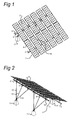
Figure 1 is a perspective view obliquely from the front and from above; -
Figure 2 is a perspective view obliquely from the rear and from above; -
Figure 3 is a rear view; -
Figure 4 is a cross section; -
Figure 5 shows on a larger scale the detail according to V fromFigure 4 ; and -
Figure 6 is a perspective view of the detail fromFigure 5 . - The device represented in
Figures 1-4 has amain frame 1 consisting of thelongitudinal runners 2 and thecross runners 3 which join the longitudinal runners together. Furthermore, thestrut 14 is fastened to thelongitudinal runners 2. Thisstrut 14 is directed obliquely, in such a way that themain frame 1 is shear rigid in the plane defined by the longitudinal and cross runners. On themain frame 1, theauxiliary frames 5 are supported in thebearing blocks 24 withrotary bearings 6, as shown inFigures 5 and 6 . These auxiliary frames each consist of acarrier 7 with arms 8 attached thereto so as to be spread out in a uniform manner. Thepanels 9, in this case with photovoltaic cells, are fastened to these arms. Theauxiliary frames 5 with the panels can be rotated in an oblique position, about the axis of thecarriers 7, depending on the position of the sun, by means of the adjusting device, the adjustingrod 10 of which is represented inFigures 1-3 . - The
main frame 1 is supported on a substrate by means of thebases 11. The lowerlongitudinal runner 2 is directly supported on thebases 11 viajunction points 4 to be described in greater detail. The upperlongitudinal runner 2 is supported by means of therods Figure 3 , some of theserods 13 are directed perpendicularly to thelongitudinal runners 2,other rods 12 diverge obliquely. The rods 12-14 haveoblate fastening lips 23 at both ends. - Each of the
rods 13 is fastened to the upperlongitudinal runner 2 by ajunction point 4, as is represented on a larger scale inFigures 5 and 6 . These junction points each consist of twofitting pieces longitudinal runner 2 is clamped by means of abolt connection 17. The fitting pieces haveledges 18 between which thelongitudinal runner 2, which is embodied as a C-shaped profile, is trapped. Furthermore, they havefastening flanges 19, to each of which anoblate fastening lip 23 of therods 20 is fastened. These tworods 20 together form thecross runner 3. The bottomfitting piece 16 also has asupport flange 21 to which thefastening lip 23 of therod 13 is fastened. - The top
fitting piece 15 has anupright bracket 22 to which therotary bearing 6 is fitted. - The
carriers 7, and thus theauxiliary frames 5 with thepanels 9, are therefore fitted at a certain height above themain frame 1, in such a way that rotations thereof about the axis of thecarriers 7 are possible. - Like the upper
longitudinal runner 2, the lowerlongitudinal runner 2 is also supported on abase 11 by ajunction point 4 of this type, thesupport flange 21 then being fastened directly thereto without the intervention of a rod. Furthermore, the bottom ends of the obliquely upwardly divergingrods 12 are fastened to said junction points 4. The bottom end of the obliquely positionedstrut 14 is also fastened to one of said junction points. - The connection between the
longitudinal runners 2 and thecarriers 7 is embodied in all cases withjunction points 4 of this type. However, in the case of some of saidjunction points 4, thefastening flanges 19 remain unused because thecross runners 3 orrods 20 are omitted there. The support flanges 21 are not used in all cases either: some of thejunction points 4 on the lowerlongitudinal runner 2 function merely as a connection between thecarriers 7 and thelongitudinal runner 2. Nevertheless, one and thesame junction point 4 can be used in all cases for each connection between themain frame 1,auxiliary frames 5 androds - List of reference symbols
- 1.
- Main frame
- 2.
- Longitudinal runner
- 3.
- Cross runner
- 4.
- Universal junction point
- 5.
- Auxiliary frame
- 6.
- Rotary bearing
- 7.
- Carrier
- 8.
- Arm
- 9.
- Panel
- 10.
- Adjusting rod
- 11.
- Base
- 12.
- Rod
- 13.
- Rod
- 14.
- Strut
- 15.
- Fitting piece
- 16.
- Fitting piece
- 17.
- Bolt connection
- 18.
- Ledge
- 19.
- Fastening flange
- 20.
- Rod, cross runner
- 21.
- Support flange
- 22.
- Bracket
- 23.
- Fastening lip
- 24.
- Bearing block
Claims (15)
- Carrier device for elements (9) intended for absorbing and/or reflecting and/or focusing solar radiation, such as solar cells, solar collectors, mirrors, lenses and the like, comprising a main frame (1) made up of longitudinal runners (2) extending parallel next to one another and cross runners (3) extending transversely to the longitudinal runners, auxiliary frames (5), which are rotatably attached to the main frame (1), for the elements (9), and also a support construction (11-13) acting on two of the longitudinal runners (2), characterized in that universal junction points (4) are provided, to each of which a longitudinal runner (2) and an auxiliary frame (5) are fastened.
- Device according to Claim 1, wherein a cross runner (3) is fastened to a junction point (4).
- Device according to Claim 1 or 2, wherein the support construction (11-13) is fastened to a junction point (4).
- Device according to one of the preceding claims, wherein a strut (14) is fastened to each junction point (4) of parallel longitudinal runners (2), which junction points (4) are displaced with respect to one another in the longitudinal direction of the longitudinal runners (2).
- Device according to one of the preceding claims, wherein the cross runners (3) comprise hollow rods (20), the ends of which may be formed by fastening lips (23), which ends are each connected to a junction point (4).
- Device according to one of the preceding claims, wherein the mainframe (1) comprises in each case at least two legs (12, 13) which converge and are supported on one and the same foundation.
- Device according to Claim 6, wherein the legs (12, 13) each comprise a hollow rod (20), the ends of which may be formed by fastening lips (23).
- Device according to one of the preceding claims, wherein each junction point (4) is provided with a bracket (22) to which an auxiliary frame (5) is fastened.
- Device according to one of the preceding claims, wherein the auxiliary frames (5) are rotatable about an axis which is parallel to the cross runners (3).
- Device according to one of the preceding claims, wherein each junction point (4) comprises two fitting pieces (15, 16), between each of which a longitudinal runner (2) is clamped.
- Device according to one of the preceding claims, wherein substantially all the connections between a longitudinal runner (2), a cross runner (3) and an auxiliary frame (2) are formed by universal and identical junction points (4).
- Arrangement for generating energy from solar radiation, comprising a carrier device according to one of the preceding claims with a main frame (1) made up of longitudinal runners (2) extending parallel next to one another, cross runners (3) extending transversely to the longitudinal runners, auxiliary frames (5) which are rotatably attached to the main frame, and also a support construction (11-13) acting on the main frame (1), wherein the auxiliary frames (5) are provided with elements (9) intended for absorbing or reflecting solar radiation, such as solar cells, solar collectors, mirrors and the like.
- Universal junction point (4) for a device according to one of Claims 1-12 for a device according to Claim 10, comprising two fitting pieces (15, 16).
- Universal junction point according to Claim 13, wherein the fitting pieces (15, 16) each have a bearing surface intended to rest against a surface of a longitudinal runner (2), and one of the fitting pieces (15, 16) comprises a bracket (22) provided with a bearing block (24).
- Universal junction point according to Claim 14, wherein the fitting pieces comprise at least one fastening flange (19) and/or a support flange (21).
Applications Claiming Priority (1)
| Application Number | Priority Date | Filing Date | Title |
|---|---|---|---|
| NL2002779A NL2002779C2 (en) | 2009-04-23 | 2009-04-23 | BEARING DEVICE FOR SOLAR PANELS. |
Publications (1)
| Publication Number | Publication Date |
|---|---|
| EP2244035A1 true EP2244035A1 (en) | 2010-10-27 |
Family
ID=41478769
Family Applications (1)
| Application Number | Title | Priority Date | Filing Date |
|---|---|---|---|
| EP10160814A Withdrawn EP2244035A1 (en) | 2009-04-23 | 2010-04-23 | Carrier device for solar panels |
Country Status (2)
| Country | Link |
|---|---|
| EP (1) | EP2244035A1 (en) |
| NL (1) | NL2002779C2 (en) |
Cited By (2)
| Publication number | Priority date | Publication date | Assignee | Title |
|---|---|---|---|---|
| US7980002B2 (en) * | 2004-11-16 | 2011-07-19 | Röhren-und Pumpenwerk Bauer Gesellschaft mbH | Rotary drum for the aerobic heating of pourable solids |
| ES2408505A1 (en) * | 2011-11-03 | 2013-06-20 | Mecanizados Solares, S.L. | Polar-axis solar tracker |
Families Citing this family (1)
| Publication number | Priority date | Publication date | Assignee | Title |
|---|---|---|---|---|
| US10673373B2 (en) | 2016-02-12 | 2020-06-02 | Solarcity Corporation | Building integrated photovoltaic roofing assemblies and associated systems and methods |
Citations (8)
| Publication number | Priority date | Publication date | Assignee | Title |
|---|---|---|---|---|
| US5125608A (en) * | 1989-04-25 | 1992-06-30 | 700 Solar Club, Inc. | Photovoltaic panel support assembly |
| EP1313151A2 (en) * | 2001-11-20 | 2003-05-21 | Gilberto Mattiuzzo | Device for converting solar radiation into electric power |
| DE102006022982A1 (en) * | 2006-04-12 | 2007-10-18 | Georg Kredler | Solar module assembling device, has planar holding frame supported rotatably or swivelably in point at elevation, whose surfaces that are rolled and/or sliding in area of joint and mountings are extracted together to influences of weather |
| DE202007017719U1 (en) * | 2007-12-17 | 2008-03-06 | Pietrzak, Arnd | System for supporting energy production from solar radiation |
| EP1903155A1 (en) * | 2006-09-22 | 2008-03-26 | Gossamer Space Frames | Space frames and connection node arrangement for them |
| WO2008096193A1 (en) * | 2007-02-05 | 2008-08-14 | Claudio Londero | System for producing energy with solar panels |
| EP1990586A1 (en) * | 2007-05-10 | 2008-11-12 | PVStrom GmbH & Co.KG | Supporting system for a tracking solar installation and mounting set |
| WO2009038294A2 (en) * | 2007-09-18 | 2009-03-26 | Urban Environment Engineering Co., Ltd. | Solar power plant |
-
2009
- 2009-04-23 NL NL2002779A patent/NL2002779C2/en not_active IP Right Cessation
-
2010
- 2010-04-23 EP EP10160814A patent/EP2244035A1/en not_active Withdrawn
Patent Citations (8)
| Publication number | Priority date | Publication date | Assignee | Title |
|---|---|---|---|---|
| US5125608A (en) * | 1989-04-25 | 1992-06-30 | 700 Solar Club, Inc. | Photovoltaic panel support assembly |
| EP1313151A2 (en) * | 2001-11-20 | 2003-05-21 | Gilberto Mattiuzzo | Device for converting solar radiation into electric power |
| DE102006022982A1 (en) * | 2006-04-12 | 2007-10-18 | Georg Kredler | Solar module assembling device, has planar holding frame supported rotatably or swivelably in point at elevation, whose surfaces that are rolled and/or sliding in area of joint and mountings are extracted together to influences of weather |
| EP1903155A1 (en) * | 2006-09-22 | 2008-03-26 | Gossamer Space Frames | Space frames and connection node arrangement for them |
| WO2008096193A1 (en) * | 2007-02-05 | 2008-08-14 | Claudio Londero | System for producing energy with solar panels |
| EP1990586A1 (en) * | 2007-05-10 | 2008-11-12 | PVStrom GmbH & Co.KG | Supporting system for a tracking solar installation and mounting set |
| WO2009038294A2 (en) * | 2007-09-18 | 2009-03-26 | Urban Environment Engineering Co., Ltd. | Solar power plant |
| DE202007017719U1 (en) * | 2007-12-17 | 2008-03-06 | Pietrzak, Arnd | System for supporting energy production from solar radiation |
Cited By (2)
| Publication number | Priority date | Publication date | Assignee | Title |
|---|---|---|---|---|
| US7980002B2 (en) * | 2004-11-16 | 2011-07-19 | Röhren-und Pumpenwerk Bauer Gesellschaft mbH | Rotary drum for the aerobic heating of pourable solids |
| ES2408505A1 (en) * | 2011-11-03 | 2013-06-20 | Mecanizados Solares, S.L. | Polar-axis solar tracker |
Also Published As
| Publication number | Publication date |
|---|---|
| NL2002779C2 (en) | 2010-10-26 |
Similar Documents
| Publication | Publication Date | Title |
|---|---|---|
| US8684190B2 (en) | Multi-position solar panel rack | |
| AU2010200576B8 (en) | Support Structure for Solar Collector | |
| CN102819268B (en) | Solid space construction package | |
| US20110197584A1 (en) | Beam down system solar generation device | |
| EP2244035A1 (en) | Carrier device for solar panels | |
| SK500162009U1 (en) | Set of photovoltaic cells on panels with an adjustable position | |
| KR200461381Y1 (en) | Angle control apparatus of solar collector | |
| EP2962047B1 (en) | Solar unit assembly and a method for constructing such an assembly | |
| CN209823678U (en) | Photovoltaic bracket component suitable for low latitude area and combined frame thereof | |
| CN202885320U (en) | Water heater support | |
| CN217721062U (en) | Photovoltaic module anchoring system of flat-inclined single photovoltaic tracker | |
| CN201327232Y (en) | Moveable heat pipe supporting frame for solar collector | |
| CN102706019B (en) | Water heater support | |
| CN216929935U (en) | Multidirectional regulation solar photovoltaic support with accomodate structure | |
| CN209146638U (en) | A kind of novel heliostat radix saposhnikoviae quakeproof bracket | |
| CN207442754U (en) | A kind of photovoltaic plate bracing frame | |
| CN211720511U (en) | High-efficiency photovoltaic power generation device with light condensing device | |
| WO2013026456A1 (en) | A solar collector unit and a method of providing such a solar collector unit | |
| CN116399040A (en) | Photoelectric heating and heat collecting mechanism with tracking and angle compensation functions | |
| CN208567170U (en) | It is a kind of convenient for fixed photo-thermal power generation bracket | |
| CN110068160B (en) | Photovoltaic and photo-thermal integrated utilization device | |
| CN212752176U (en) | Novel solar panel support | |
| CN209787104U (en) | Sun tracking type solar photovoltaic device | |
| CN213960004U (en) | Photovoltaic power plant support convenient to adjust angle of elevation | |
| CN209963992U (en) | High-efficient solar photovoltaic power generation device convenient to adjust |
Legal Events
| Date | Code | Title | Description |
|---|---|---|---|
| PUAI | Public reference made under article 153(3) epc to a published international application that has entered the european phase |
Free format text: ORIGINAL CODE: 0009012 |
|
| AK | Designated contracting states |
Kind code of ref document: A1 Designated state(s): AT BE BG CH CY CZ DE DK EE ES FI FR GB GR HR HU IE IS IT LI LT LU LV MC MK MT NL NO PL PT RO SE SI SK SM TR |
|
| AX | Request for extension of the european patent |
Extension state: AL BA ME RS |
|
| 17P | Request for examination filed |
Effective date: 20110427 |
|
| RIN1 | Information on inventor provided before grant (corrected) |
Inventor name: PRINS, VINCENT Inventor name: VAN DEURSEN, ADRIANUS GERARDUS Inventor name: BROOS, JOHAN MARTIEN |
|
| STAA | Information on the status of an ep patent application or granted ep patent |
Free format text: STATUS: THE APPLICATION HAS BEEN WITHDRAWN |
|
| 18W | Application withdrawn |
Effective date: 20150126 |