EP2243964B1 - Steuerventil - Google Patents
Steuerventil Download PDFInfo
- Publication number
- EP2243964B1 EP2243964B1 EP10158618.8A EP10158618A EP2243964B1 EP 2243964 B1 EP2243964 B1 EP 2243964B1 EP 10158618 A EP10158618 A EP 10158618A EP 2243964 B1 EP2243964 B1 EP 2243964B1
- Authority
- EP
- European Patent Office
- Prior art keywords
- slide
- control valve
- flow
- consumer
- actuator
- Prior art date
- Legal status (The legal status is an assumption and is not a legal conclusion. Google has not performed a legal analysis and makes no representation as to the accuracy of the status listed.)
- Not-in-force
Links
Images

Classifications
-
- E—FIXED CONSTRUCTIONS
- E02—HYDRAULIC ENGINEERING; FOUNDATIONS; SOIL SHIFTING
- E02F—DREDGING; SOIL-SHIFTING
- E02F9/00—Component parts of dredgers or soil-shifting machines, not restricted to one of the kinds covered by groups E02F3/00 - E02F7/00
- E02F9/20—Drives; Control devices
- E02F9/22—Hydraulic or pneumatic drives
- E02F9/2203—Arrangements for controlling the attitude of actuators, e.g. speed, floating function
-
- F—MECHANICAL ENGINEERING; LIGHTING; HEATING; WEAPONS; BLASTING
- F15—FLUID-PRESSURE ACTUATORS; HYDRAULICS OR PNEUMATICS IN GENERAL
- F15B—SYSTEMS ACTING BY MEANS OF FLUIDS IN GENERAL; FLUID-PRESSURE ACTUATORS, e.g. SERVOMOTORS; DETAILS OF FLUID-PRESSURE SYSTEMS, NOT OTHERWISE PROVIDED FOR
- F15B11/00—Servomotor systems without provision for follow-up action; Circuits therefor
- F15B11/02—Systems essentially incorporating special features for controlling the speed or actuating force of an output member
- F15B11/04—Systems essentially incorporating special features for controlling the speed or actuating force of an output member for controlling the speed
- F15B11/046—Systems essentially incorporating special features for controlling the speed or actuating force of an output member for controlling the speed depending on the position of the working member
- F15B11/048—Systems essentially incorporating special features for controlling the speed or actuating force of an output member for controlling the speed depending on the position of the working member with deceleration control
-
- F—MECHANICAL ENGINEERING; LIGHTING; HEATING; WEAPONS; BLASTING
- F15—FLUID-PRESSURE ACTUATORS; HYDRAULICS OR PNEUMATICS IN GENERAL
- F15B—SYSTEMS ACTING BY MEANS OF FLUIDS IN GENERAL; FLUID-PRESSURE ACTUATORS, e.g. SERVOMOTORS; DETAILS OF FLUID-PRESSURE SYSTEMS, NOT OTHERWISE PROVIDED FOR
- F15B13/00—Details of servomotor systems ; Valves for servomotor systems
- F15B13/02—Fluid distribution or supply devices characterised by their adaptation to the control of servomotors
- F15B13/04—Fluid distribution or supply devices characterised by their adaptation to the control of servomotors for use with a single servomotor
- F15B13/0401—Valve members; Fluid interconnections therefor
- F15B13/0402—Valve members; Fluid interconnections therefor for linearly sliding valves, e.g. spool valves
Definitions
- the present invention relates to a control valve according to the preamble of claim 1.
- Vehicles with wagon bridges e.g. tipping lorries
- tipping lorries are commonly used for transport of materials such as gravel and soil to and from construction locations, wherein the load is tipped at the desired location by means of a tipping cylinder arranged on the wagon bridge.
- the hydraulic cylinder on such tipping arrangements is usually of a single-acting telescoping type.
- the hydraulic cylinder is of the type that includes a number of cylinder sections comprised in each other and mounted between the wagon bridge and vehicle frame, which sections by the action of a pressurized fluid may be extended in a number of sequential steps.
- the telescopic cylinder When the wagon bridge is to be lowered from a tilted and substantially vertical tipping position to a horizontal position the telescopic cylinder is retracted under the influence of the weight of the wagon bridge.
- the maximum velocity at which the wagon bridge may be lowered is limited by the flow through the control valve, wherein the flow limitation also implies that the vehicle remains stationary and ineffective while the wagon bridge is lowered towards a bottom position in which the wagon bridge rests horizontally and the vehicle is ready to fetch a new load. This is a disadvantage that of course impairs the degree of utilization of the capacity and efficiency of the vehicle.
- SE 526 222 discloses a control valve that solves this problem by allowing the flow to take two paths past the slide upon emptying of the consumer and lowering of a load. Hence, the flow through the valve is larger in the direction in which the hydraulic cylinder is emptied of its fluid for lowering of the wagon bridge after tipping than at filling of the hydraulic cylinder for raising of the wagon bridge.
- this conventional control valve includes a valve housing that houses a slidably arranged slide, openings or ports that are connected to a source for emitting a pressurized fluid, and to a consumer that e.g. may be a hydraulic cylinder or a tank for collection and storage of surplus fluid.
- the slide has a first and a second end, respectively, and is displaceable in the valve housing for controlling of the flow between an inlet port in connection to the pressure source and an outlet port that is connected to the consumer, or alternatively, from the consumer to the tank.
- the valve housing is provided with a bore that makes sure that the flow at emptying of the hydraulic cylinder may take two paths over the slide, namely a first flow path over the first end of the slide, and a second flow path over the second end of the slide. In other words, at draining of the consumer to the tank, the flow is led via both these flow paths from the consumer to the tank.
- EP 1 729 014 A2 discloses a control valve for maneuvering a hydraulic consumer such as a single acting telescopic cylinder, including a valve housing with an inlet port connected to a pump for delivering of a hydraulic flow, a motor port to which said consumer is connected, an outlet port connected to a tank, and a maneuverable slide provided with port tracks and arranged in the valve housing with a first and a second end, respectively, which slide is adapted to control the hydraulic flow between the inlet port and the consumer and between the consumer and the tank, wherein the valve housing includes a first flow path over the first end of the slide and a second flow path over the second end of the slide, wherein the return flow from the consumer to the tank may be led via said flow paths through the valve housing, wherein the control valve includes a regulating device connected to the slide, which device from a position with maximal velocity at lowering of a load, in which the return flow from the consumer is conveyed via both the first and the second flow paths over the first end and the second end of the slide,
- An object of the present invention is to provide a control valve of the type described above, but with an improved controlling performance and which control valve although it allows a very sudden lowering of the wagon bridge it also allows regulation of the flow velocity of the control valve during lowering of a load.
- a further object of the invention is to provide a control valve that makes it possible to simultaneously, at an arbitrary moment during a commenced tipping operation, take command of the control valve and limit the flow and thus the maximal velocity of the lowering velocity of the load. On modern vehicles, the space for installation of pneumatic operating devices is very limited.
- a third object of the invention is therefore to achieve a control valve that allows electrical remote controlling and that is easily implemented in an operator's cab and may be controlled with electrical push buttons from the cab.
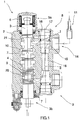
- the known control valve 1 of figure 1 for directional control of the flow of fluid includes a valve housing 2, in which a slide 3 is arranged to slide inside a sleeve 4.
- the slide 3 is arranged to be slidably and continuously displaced in the sleeve 4 between a first and a second end position.
- the slide 3 has a first and a second end 3a and 3b, respectively, wherein means in form of a compression spring 6 is arranged at said first end and wherein the second end extends through a sealing 7. As long as the slide 3 is unaffected by the operator it strives to assume a neutral position under the action of the compression spring 6.
- the valve housing 2 is divided into a first side 8, defined as the part of the valve housing that the slide's first end 3a is located in, and a second side 9, defined as the part of the valve housing that the slide's second end 3b is located in.
- the slide 3 exhibits a number of machined port tracks 10 through which fluid may pass. At displacement of the slide 3 the corresponding ports in the valve housing 2 are opened or closed, respectively.
- the reference numeral 11 denotes a consumer in the form of a single acting and telescoping hydraulic cylinder that may communicate with one of said ports.
- the valve housing 2 is provided with an inlet 12 and an outlet 13.
- the inlet 12 is connected to a pump (not shown), which delivers a hydraulic flow.
- the outlet 13 is connected to a tank (not shown).
- a connection 14 (denoted A in Fig. 2a-2d ), i.e., a so-called motor port, for conveying fluid to the consumer 11 is arranged between the inlet 12 and the outlet 13.
- the motor port 14 is provided with a bore in form of an eccentric areal enlargement 15 in order to increase the available flow area from the consumer 11 through the valve housing 2 and via the outlet 13 to the tank. The increase of the flow arises since the return flow from the consumer 11 may flow via two paths back to the tank.
- the areal enlargement 15 is eccentrically located in relation to the original connection. Adjacent to the areal enlargement there is a sealing ring 16 which encloses a sealing stopper 17.
- the sealing stopper 17 is a substitute to a pressure relieving valve that conventionally is mounted in connection to the motor port 14.
- a bored channel 18 in the axial direction of the stopper 17 extends through the valve housing 2 at a substantially right angle with respect to the motor port 14 that is located at the first end of the channel 18.
- the motor port 14 is connected to the channel 18 and a port track 20 that is arranged in connection to an end 3b of the slide 3 that is located in the second side 9 of the valve housing.
- An enlarged port track 21 is arranged in connection to the end 3a of the slide 3 that is located in the first side 8 of the valve housing, i.e., a port track with an extended measure in the axial direction of the slide 3, which at the first end position of the slide 3 according to figure 2a communicates with the tank via a second channel 22.
- This enlargement of the port track opens up for communication with the main pressure relieving valve 19 from both the pump and the consumer.
- the first flow I is conveyed to the enlarged port track 21 in the first side 5 of the valve housing via the tank channel 22 to the outlet 13.
- the second flow II is conveyed through the bored channel 18 to the port track 20 of the slide 3 in the second side 6 of the valve housing which is connected to the centre channel 23 and further on to the tank.
- the valve housing 2 includes a first flow path over the first end 3a of the slide and a second flow path II over the second end 3b of the slide, wherein the return flow from the consumer 11 to the tank is conveyed via said flow paths through the valve housing 2.
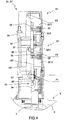
- control valve 1 is shown in a position in right angle compared to the view shown in the cross section of Fig. 1 .
- a device for regulation of the slide 3 and generally denoted with reference numeral is arranged at the control valve 1 and which jointly with the slide regulates and controls the displacement of the slide in the axial direction. Thanks to the device according to the invention the flow through the control valve 1 may be regulated although the present control valve as such is adapted to very high flow velocities at lowering of a load.
- the regulation device 30 arranged at the control valve 1 includes a first and a second pneumatic actuator 31, 31', of which the first (the rear actuator) 31 is of a single acting type while the second (the front actuator) 31' is of double acting type.
- Both the rear and the front actuator 31, 31' include one rod section 32, 32' each with a corresponding piston rod 33, 33', respectively, which are both arranged to move forth and backwards in a cylinder section 34, 34'.
- Each rod section 32, 32' defines a first and a second chamber 32:1, 32:2, and 32':1, 32':2 respectively, inside the corresponding cylinder wherein the rear piston rod 33 extends into a forwardly adjacent chamber 32':1.
- Both of the actuators 31, 31' are mounted coaxially in series one after the other such that the actuators together form an actuator unit which is uniformly arranged on the first side 8 of the valve housing 2, i.e., the part of the valve housing where the first end 3a of the slide 3 is positioned for coaxial interaction with the same.
- the piston rod 33, 33' of each actuator 31, 31' each has a rear part 36, 36', respectively, which extends in a fluid tight manner out through a forwardly adjacent butt end 37, 37' and are thus arranged that they may be brought in and out of contact with each other at 38. Namely, the front end of the rear piston rod 33 may be brought in and out of contact with the rear end of the front piston rod 33'.
- the piston rod 33 of the rear actuator 31 forms a movement limiting stop at said contact for the rod section 32' of the front actuators 31'.
- the rear actuator 31 is provided with a stroke limiting organ 39, here represented by a pair of bolts in form of an adjusting nut and a check nut by means of which of the axial position of the rear piston rod 33 in the rod section 32 may be calibrated during adjustment of the control valve 1 to a limited lowering velocity.
- a stroke limiting organ 39 here represented by a pair of bolts in form of an adjusting nut and a check nut by means of which of the axial position of the rear piston rod 33 in the rod section 32 may be calibrated during adjustment of the control valve 1 to a limited lowering velocity.
- Such calibration is normally only performed at rare occasions and in conjunction with adaptation of the control valve 1 with respect to the hydraulic units it is arranged to control.
- a connecting device 40 is closely shown, which has a shape that locks the slide 3 at the end of the front piston rod 33'.
- the connecting device 40 includes a thickened part 42 housed in an undercut track 41, wherein axial power transmission between the front end of the piston rod 33' and the first end 3a of the slide 3 is allowed in both the pulling and the pressing direction.
- Both of the actuators 31, 31' are provided with inlets or ports denoted P1, P2 and P3 for letting in an air pressure medium that functions as a signal feeding for adjustment or positioning of the respective rod sections 32, 32' in relation to each other in the corresponding cylinder 34, 34'.
- the actuator unit 31, 31' as a whole comprises three inlet ports P1, P2, P3, wherein the signals to said inlet ports are generated by the control circuit 46 shown in Fig. 3 .
- the ports P1, P2, P3 may be put in and out of connection to the atmosphere or a pressure medium source, respectively by actuation of valve means 47, 48, 49, in form of a corresponding electromagnetically adjustable two-way valve, arranged via signaling lines 43, 44, 45 to each port.
- the electromagnetic valves 47, 48, 49 are affected by a voltage of 24 volts and are connected and disconnected by means of switches 50, 51, 52 such as push buttons adapted to be placed on a distance from the control valve 1 and in communication with the corresponding actuator unit 30 by means of electrical lines 60, 61, 62.
- switches 50, 51, 52 such as push buttons adapted to be placed on a distance from the control valve 1 and in communication with the corresponding actuator unit 30 by means of electrical lines 60, 61, 62.
- One of the major advantages of the possibility of electrical remote controlling of the actuator unit 31, 31' is that electrical lines are very simple to implement in e.g. the operator's cab of a vehicle in comparison to pneumatic signaling lines.
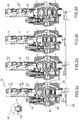
- the control valve 1 functions in such a manner that is possible to obtain a lowering velocity that is adaptable to the load, through switching of the air pressure to the ports P1, P2, P3 of the actuator unit 31, 31' by means of a push of a button, wherein the actuator unit pulls or pushes the slide in the desired manner in the valve housing 2.
- a and B denotes the motor ports of the control valve 1
- P and T denotes the control valve's 1 inlet port for the pressure side and outlet port to the tank, respectively.
- the device has the following operational function: As illustrated in Fig. 2a , the control valve 1 is adjusted for maximal lowering velocity denoted "Super Rapid” in which position the port P1 is fed with a signal "1" at the same time as the two other ports P2 and P3 receives no signal "0", i.e., P2 and P3 are set to atmospheric pressure. Under the influence of the compressed air at port P1 the rod section 32' of the front actuators 31' are forced to a rear end position in the cylinder and under the influence of said rod section the rear rod section 32 of the actuator 31 is forced backwards to its rear end position. As a consequence, the slide 3 is retracted about 7 mm into the valve housing 2 with respect to the centre line 53. In this position maximal lowering velocity is achieved in that the cylinder 11 is drained of its fluid via both the first flow path over the first end 3a of the slide 3and the second flow path II over the second end 3b of the slide 3. Also, see Fig. 1 .
- the ports P1 and P3 are fed with pressure signals "1" while the port P2 receives no signal "0" and are set to atmospheric pressure.
- the rod section 32' of the front actuator 31' is forced backwards at the same time as the rod section 32 of the rear actuator 31 is forced forward.
- the rear rod section 32 acts, by means of its comparatively larger area, as a stop for the front rod section 32' when they reach each other.
- the slide is only retracted about 3 mm into the valve housing 2.
- a comparatively slow lowering velocity is provided, which is denoted "Slow Motion", in that the cylinder 11 is drained of its fluid in a limited manner since the flow is only conveyed via the first flow path I over the first end 3a of the slide 3.
- the second flow path II i.e., over the second end 3b of the slide 3.
- the flow mounts to about 50 % of the flow at the maximal lowering velocity "Super Rapid”.
- the control valve is adjusted into a neutral position "Neutral", in which position the port P2 is fed with a signal "1" at the same time as the two other ports P1 and P3 receives no signal "0", or alternatively none of the ports P1, P2, P3 receives a signal "0", wherein each of the ports are set to atmospheric pressure.
- the slide 3 In the neutral position the slide 3 is balanced on the centre line 53, i.e., 0 mm, under the action of the actuator unit 31, 31'.
- Fig. 2d the device is adjusted to the raising position "Raise", in which position the port P2 is fed with a signal "1" at the same time as the two other ports P1 and P3 receives no signal "0".
- the slide 3 is forced about 7 mm out of the valve housing 2, under the action of the actuator unit 31, 31', wherein pressurized fluid flows from the inlet 12 to the motor port 14 (denoted A in Fig. 2a-2d ) and from there further on to the consumer 11.
Landscapes
- Engineering & Computer Science (AREA)
- General Engineering & Computer Science (AREA)
- Physics & Mathematics (AREA)
- Fluid Mechanics (AREA)
- Mechanical Engineering (AREA)
- Mining & Mineral Resources (AREA)
- Civil Engineering (AREA)
- Structural Engineering (AREA)
- Multiple-Way Valves (AREA)
- Fluid-Pressure Circuits (AREA)
- Valve Housings (AREA)
Claims (9)
- Steuerventil (1) zur Betätigung eines hydraulischen Verbrauchers (11), wie z.B. eines einzeln wirkenden Teleskopzylinders, mit einem Ventilgehäuse (2) mit einem Einlassanschluss (12), der mit einer Pumpe zur Abgabe eines Hydraulikflusses verbunden ist, einem Motoranschluss (14) mit dem der Verbraucher (11) verbunden ist, einem Auslassanschluss (13), der mit einem Tank verbunden ist, und einen verfahrbaren Schieber (3), der mit Anschlussstücken (7, 20, 21) versehen und in dem Ventilgehäuse mit einem ersten bzw. einem zweiten Ende (3a, 3b) angeordnet ist, wobei der Schieber so ausgebildet ist, dass er den Hydraulikfluss zwischen dem Einlassanschluss und dem Verbraucher und zwischen dem Verbraucher und dem Tank steuert, wobei das Ventilgehäuse einen ersten Strömungsweg (I) über das erste Ende (3a) des Schiebers und einen zweiten Strömungsweg (II) über das zweite Ende (3b) des Schiebers einschließt, wobei der Rückstrom vom Verbraucher zum Tank über die genannten Strömungswege durch das Ventilgehäuse geführt werden kann, wobei das Steuerventil (1) eine mit dem Schieber (3) verbundene Regelvorrichtung (30) enthält, wobei die Vorrichtung aus einer Position mit maximaler Geschwindigkeit beim Absenken einer Last, in der der Rückstrom vom Verbraucher (11) sowohl über den ersten als auch über den zweiten Strömungsweg (I, II) über das erste Ende (3a) und das zweite Ende (3b) des Schiebers geleitet wird, angeordnet ist, um eine begrenzte Absenkgeschwindigkeit durch Ausrichtung des Schiebers in der axialen Richtung und Fördern des Flusses nur über den ersten Strömungsweg (I) am ersten Ende (3a) des Schiebers bereitzustellen, wobei die Regeleinrichtung (30) eine Betätigungseinheit (31, 31') aufweist, die einheitlich auf der Seite des Ventilgehäuses (2) angeordnet ist, der das erste Ende (3a) des Schiebers (3) zugewandt ist, dadurch gekennzeichnet, dass die Betätigungseinheit (31, 31') aus einem ersten und einem zweiten pneumatisch wirkenden Aktuator (31, 31') gebildet ist, die koaxial hintereinander angeordnet sind, von denen jeder einen Stangenabschnitt (32, 32') mit einer entsprechenden Kolbenstange (33, 33') aufweist, die beide innerhalb eines Zylinderabschnitts (34, 34') vorwärts und rückwärts beweglich angeordnet sind, wobei der erste Stangenabschnitt des Aktuators (32) einen positiven Anschlag für den zweiten Stangenabschnitt (32') des Aktuators bildet.
- Steuerventil nach Anspruch 1, wobei die Betätigungseinheit (31, 31') ein hubbegrenzendes Organ (39) aufweist, durch das die axiale Position der ersten Kolbenstange (33) im Stangenabschnitt bei Einstellung auf die begrenzte Absenkgeschwindigkeit eingestellt kann werden.
- Steuerventil nach Anspruch 1 oder 2, wobei jeder Stangenabschnitt (32, 32') eine erste bzw. eine zweite Kammer (32:1, 32:2; 32':1, 32':2) in dem entsprechenden Zylinderabschnitt (34, 34') definiert und wobei der Stangenabschnitt (33) des ersten Aktuators (31) sich teilweise in die erste Kammer (32':1) des zweiten Aktuators (31') erstreckt.
- Steuerventil nach einem der vorstehenden Ansprüche 1-3, mit einer Verbindungsvorrichtung (40), die so ausgebildet ist, dass sie das erste Ende (3a) des Schiebers (3) mit der Betätigungseinheit (31, 31') fest verbindet und die axiale Kraftübertragung sowohl in Zug- als auch in Druckrichtung zwischen dem Schieber (3) und der Betätigungseinheit (31, 31') erlaubt.
- Steuerventil nach einem der vorstehenden Ansprüche 1-4, wobei die Betätigungseinheit (31, 31') Einlassöffnungen (P1, P2, P3) aufweist und wobei die Signale zu den besagten Einlassöffnungen durch eine Steuerschaltung (46) erzeugt werden.
- Steuerventil nach Anspruch 5, bei dem die Anschlüsse (P1, P2, P3) mittels Signaldruckleitungen (43, 44, 45) mit der Umgebung oder einer Druckmittelquelle in und außer Verbindung gebracht werden können und mit einem an jedem Anschluss angeordneten Ventilmittel (47, 48, 49) in Verbindung sind.
- Steuerventil nach Anspruch 6, wobei das Ventilmittel (47, 48, 49) elektromagnetisch verstellbare Ventile umfasst.
- Steuerventil nach Anspruch 7, umfassend Schalter (50, 51, 52), wie zum Beispiel Druckknöpfe, die so angeordnet sind, dass sie sich in einem Abstand von dem Steuerventil (1) befinden, und elektrische Leitungen (60, 61, 62), die sich zwischen den Druckknöpfen und den elektromagnetisch betätigbaren Ventilen erstrecken.
- Verwendung des Steuerventils nach einem der vorstehenden Ansprüche 1-8 zum Manövrieren und Steuern der Kippfunktion eines Fahrzeugs mit einer Wagenbrücke, wie zum Beispiel eines Lastkraftwagens oder dergleichen.
Priority Applications (1)
| Application Number | Priority Date | Filing Date | Title |
|---|---|---|---|
| PL10158618T PL2243964T3 (pl) | 2009-04-24 | 2010-03-31 | Zawór sterujący |
Applications Claiming Priority (1)
| Application Number | Priority Date | Filing Date | Title |
|---|---|---|---|
| SE0900563A SE533719C2 (sv) | 2009-04-24 | 2009-04-24 | Manöverventil |
Publications (3)
| Publication Number | Publication Date |
|---|---|
| EP2243964A2 EP2243964A2 (de) | 2010-10-27 |
| EP2243964A3 EP2243964A3 (de) | 2014-04-09 |
| EP2243964B1 true EP2243964B1 (de) | 2020-09-16 |
Family
ID=42320888
Family Applications (1)
| Application Number | Title | Priority Date | Filing Date |
|---|---|---|---|
| EP10158618.8A Not-in-force EP2243964B1 (de) | 2009-04-24 | 2010-03-31 | Steuerventil |
Country Status (3)
| Country | Link |
|---|---|
| EP (1) | EP2243964B1 (de) |
| PL (1) | PL2243964T3 (de) |
| SE (1) | SE533719C2 (de) |
Families Citing this family (1)
| Publication number | Priority date | Publication date | Assignee | Title |
|---|---|---|---|---|
| CN108411970A (zh) * | 2018-04-28 | 2018-08-17 | 黄宇松 | 一种水利工程用清淤装置 |
Family Cites Families (4)
| Publication number | Priority date | Publication date | Assignee | Title |
|---|---|---|---|---|
| DE19934053C2 (de) * | 1999-07-19 | 2002-12-12 | Bosch Rexroth Teknik Ab Stockholm | Mehrwegeventil |
| SE526222C2 (sv) | 2003-12-02 | 2005-08-02 | Hydrauto Valves Ab | Manöverventil för manövrering av en hydraulisk förbrukare såsom en enkelverkande teleskopcylinder |
| DE102005025441A1 (de) * | 2005-06-02 | 2006-12-14 | Bosch Rexroth Aktiengesellschaft | Steuerblock und Steuerblocksektion |
| CN101506532B (zh) * | 2006-09-04 | 2014-11-26 | 株式会社岛津制作所 | 流体控制阀 |
-
2009
- 2009-04-24 SE SE0900563A patent/SE533719C2/sv not_active IP Right Cessation
-
2010
- 2010-03-31 EP EP10158618.8A patent/EP2243964B1/de not_active Not-in-force
- 2010-03-31 PL PL10158618T patent/PL2243964T3/pl unknown
Non-Patent Citations (1)
| Title |
|---|
| None * |
Also Published As
| Publication number | Publication date |
|---|---|
| EP2243964A2 (de) | 2010-10-27 |
| PL2243964T3 (pl) | 2020-12-14 |
| EP2243964A3 (de) | 2014-04-09 |
| SE533719C2 (sv) | 2010-12-14 |
| SE0900563A1 (sv) | 2010-10-25 |
Similar Documents
| Publication | Publication Date | Title |
|---|---|---|
| AU2008201612B2 (en) | A dump truck | |
| US4170279A (en) | Fluid flow control devices | |
| EP1752587B1 (de) | Hydraulische Anordnung | |
| US3381833A (en) | Self-synchronizing load lifting and lowering system for straddle carriers and the like | |
| US20110120297A1 (en) | Hydraulic Circuit | |
| JP3237377B2 (ja) | フォーク移動装置 | |
| US5115720A (en) | Hydraulic valve bank | |
| US6926113B2 (en) | Cushioned steering for articulated vehicle | |
| US5832808A (en) | Directional control valve unit | |
| EP2243964B1 (de) | Steuerventil | |
| US3793831A (en) | Electrolic control valve | |
| EP1335850B1 (de) | Hydraulische kippvorrichtung für fahrerhäuser von lastkraftwagen, und kraftfahrzeug mit derartiger kippvorrichtung | |
| US11378989B2 (en) | Hydraulic valve with switching regeneration circuit | |
| US5944204A (en) | Hydraulic boom compensation system for aerial devices | |
| US3738520A (en) | Clamp mechanism with trailing arm control | |
| AU2006285807A1 (en) | Hydraulic drive device for vertical pivoting movement of load carrying platform | |
| US20230354733A1 (en) | Hydraulic adjustment device | |
| US4913616A (en) | Hydraulic implement regeneration system | |
| US7044705B2 (en) | Load handling machine | |
| CN110816697B (zh) | 一种搭载电控一体泵马达驱动系统的履带车辆及驱动控制方法 | |
| US3733964A (en) | Fluid control system | |
| CN109854558B (zh) | 液压系统和工程车辆 | |
| JP4132656B2 (ja) | 荷役車両の油圧装置 | |
| CN220200267U (zh) | 自装卸式垃圾车及其液压控制系统 | |
| US7320272B2 (en) | Hydraulic system |
Legal Events
| Date | Code | Title | Description |
|---|---|---|---|
| PUAI | Public reference made under article 153(3) epc to a published international application that has entered the european phase |
Free format text: ORIGINAL CODE: 0009012 |
|
| AK | Designated contracting states |
Kind code of ref document: A2 Designated state(s): AT BE BG CH CY CZ DE DK EE ES FI FR GB GR HR HU IE IS IT LI LT LU LV MC MK MT NL NO PL PT RO SE SI SK SM TR |
|
| AX | Request for extension of the european patent |
Extension state: AL BA ME RS |
|
| PUAL | Search report despatched |
Free format text: ORIGINAL CODE: 0009013 |
|
| AK | Designated contracting states |
Kind code of ref document: A3 Designated state(s): AT BE BG CH CY CZ DE DK EE ES FI FR GB GR HR HU IE IS IT LI LT LU LV MC MK MT NL NO PL PT RO SE SI SK SM TR |
|
| AX | Request for extension of the european patent |
Extension state: AL BA ME RS |
|
| RIC1 | Information provided on ipc code assigned before grant |
Ipc: F15B 13/04 20060101AFI20140304BHEP |
|
| 17P | Request for examination filed |
Effective date: 20140801 |
|
| RBV | Designated contracting states (corrected) |
Designated state(s): AT BE BG CH CY CZ DE DK EE ES FI FR GB GR HR HU IE IS IT LI LT LU LV MC MK MT NL NO PL PT RO SE SI SK SM TR |
|
| STAA | Information on the status of an ep patent application or granted ep patent |
Free format text: STATUS: EXAMINATION IS IN PROGRESS |
|
| 17Q | First examination report despatched |
Effective date: 20171108 |
|
| GRAP | Despatch of communication of intention to grant a patent |
Free format text: ORIGINAL CODE: EPIDOSNIGR1 |
|
| STAA | Information on the status of an ep patent application or granted ep patent |
Free format text: STATUS: GRANT OF PATENT IS INTENDED |
|
| INTG | Intention to grant announced |
Effective date: 20200515 |
|
| GRAS | Grant fee paid |
Free format text: ORIGINAL CODE: EPIDOSNIGR3 |
|
| GRAA | (expected) grant |
Free format text: ORIGINAL CODE: 0009210 |
|
| STAA | Information on the status of an ep patent application or granted ep patent |
Free format text: STATUS: THE PATENT HAS BEEN GRANTED |
|
| AK | Designated contracting states |
Kind code of ref document: B1 Designated state(s): AT BE BG CH CY CZ DE DK EE ES FI FR GB GR HR HU IE IS IT LI LT LU LV MC MK MT NL NO PL PT RO SE SI SK SM TR |
|
| REG | Reference to a national code |
Ref country code: GB Ref legal event code: FG4D |
|
| REG | Reference to a national code |
Ref country code: CH Ref legal event code: EP |
|
| REG | Reference to a national code |
Ref country code: DE Ref legal event code: R096 Ref document number: 602010065450 Country of ref document: DE |
|
| REG | Reference to a national code |
Ref country code: IE Ref legal event code: FG4D |
|
| REG | Reference to a national code |
Ref country code: AT Ref legal event code: REF Ref document number: 1314395 Country of ref document: AT Kind code of ref document: T Effective date: 20201015 |
|
| REG | Reference to a national code |
Ref country code: SE Ref legal event code: TRGR |
|
| REG | Reference to a national code |
Ref country code: FI Ref legal event code: FGE |
|
| PG25 | Lapsed in a contracting state [announced via postgrant information from national office to epo] |
Ref country code: BG Free format text: LAPSE BECAUSE OF FAILURE TO SUBMIT A TRANSLATION OF THE DESCRIPTION OR TO PAY THE FEE WITHIN THE PRESCRIBED TIME-LIMIT Effective date: 20201216 Ref country code: GR Free format text: LAPSE BECAUSE OF FAILURE TO SUBMIT A TRANSLATION OF THE DESCRIPTION OR TO PAY THE FEE WITHIN THE PRESCRIBED TIME-LIMIT Effective date: 20201217 Ref country code: NO Free format text: LAPSE BECAUSE OF FAILURE TO SUBMIT A TRANSLATION OF THE DESCRIPTION OR TO PAY THE FEE WITHIN THE PRESCRIBED TIME-LIMIT Effective date: 20201216 Ref country code: HR Free format text: LAPSE BECAUSE OF FAILURE TO SUBMIT A TRANSLATION OF THE DESCRIPTION OR TO PAY THE FEE WITHIN THE PRESCRIBED TIME-LIMIT Effective date: 20200916 |
|
| REG | Reference to a national code |
Ref country code: AT Ref legal event code: MK05 Ref document number: 1314395 Country of ref document: AT Kind code of ref document: T Effective date: 20200916 |
|
| REG | Reference to a national code |
Ref country code: NL Ref legal event code: MP Effective date: 20200916 |
|
| PG25 | Lapsed in a contracting state [announced via postgrant information from national office to epo] |
Ref country code: LV Free format text: LAPSE BECAUSE OF FAILURE TO SUBMIT A TRANSLATION OF THE DESCRIPTION OR TO PAY THE FEE WITHIN THE PRESCRIBED TIME-LIMIT Effective date: 20200916 |
|
| REG | Reference to a national code |
Ref country code: LT Ref legal event code: MG4D |
|
| PG25 | Lapsed in a contracting state [announced via postgrant information from national office to epo] |
Ref country code: CZ Free format text: LAPSE BECAUSE OF FAILURE TO SUBMIT A TRANSLATION OF THE DESCRIPTION OR TO PAY THE FEE WITHIN THE PRESCRIBED TIME-LIMIT Effective date: 20200916 Ref country code: EE Free format text: LAPSE BECAUSE OF FAILURE TO SUBMIT A TRANSLATION OF THE DESCRIPTION OR TO PAY THE FEE WITHIN THE PRESCRIBED TIME-LIMIT Effective date: 20200916 Ref country code: LT Free format text: LAPSE BECAUSE OF FAILURE TO SUBMIT A TRANSLATION OF THE DESCRIPTION OR TO PAY THE FEE WITHIN THE PRESCRIBED TIME-LIMIT Effective date: 20200916 Ref country code: NL Free format text: LAPSE BECAUSE OF FAILURE TO SUBMIT A TRANSLATION OF THE DESCRIPTION OR TO PAY THE FEE WITHIN THE PRESCRIBED TIME-LIMIT Effective date: 20200916 Ref country code: PT Free format text: LAPSE BECAUSE OF FAILURE TO SUBMIT A TRANSLATION OF THE DESCRIPTION OR TO PAY THE FEE WITHIN THE PRESCRIBED TIME-LIMIT Effective date: 20210118 Ref country code: RO Free format text: LAPSE BECAUSE OF FAILURE TO SUBMIT A TRANSLATION OF THE DESCRIPTION OR TO PAY THE FEE WITHIN THE PRESCRIBED TIME-LIMIT Effective date: 20200916 Ref country code: SM Free format text: LAPSE BECAUSE OF FAILURE TO SUBMIT A TRANSLATION OF THE DESCRIPTION OR TO PAY THE FEE WITHIN THE PRESCRIBED TIME-LIMIT Effective date: 20200916 |
|
| PG25 | Lapsed in a contracting state [announced via postgrant information from national office to epo] |
Ref country code: AT Free format text: LAPSE BECAUSE OF FAILURE TO SUBMIT A TRANSLATION OF THE DESCRIPTION OR TO PAY THE FEE WITHIN THE PRESCRIBED TIME-LIMIT Effective date: 20200916 Ref country code: IS Free format text: LAPSE BECAUSE OF FAILURE TO SUBMIT A TRANSLATION OF THE DESCRIPTION OR TO PAY THE FEE WITHIN THE PRESCRIBED TIME-LIMIT Effective date: 20210116 Ref country code: ES Free format text: LAPSE BECAUSE OF FAILURE TO SUBMIT A TRANSLATION OF THE DESCRIPTION OR TO PAY THE FEE WITHIN THE PRESCRIBED TIME-LIMIT Effective date: 20200916 |
|
| REG | Reference to a national code |
Ref country code: DE Ref legal event code: R097 Ref document number: 602010065450 Country of ref document: DE |
|
| PG25 | Lapsed in a contracting state [announced via postgrant information from national office to epo] |
Ref country code: SK Free format text: LAPSE BECAUSE OF FAILURE TO SUBMIT A TRANSLATION OF THE DESCRIPTION OR TO PAY THE FEE WITHIN THE PRESCRIBED TIME-LIMIT Effective date: 20200916 |
|
| PLBE | No opposition filed within time limit |
Free format text: ORIGINAL CODE: 0009261 |
|
| STAA | Information on the status of an ep patent application or granted ep patent |
Free format text: STATUS: NO OPPOSITION FILED WITHIN TIME LIMIT |
|
| 26N | No opposition filed |
Effective date: 20210617 |
|
| PG25 | Lapsed in a contracting state [announced via postgrant information from national office to epo] |
Ref country code: SI Free format text: LAPSE BECAUSE OF FAILURE TO SUBMIT A TRANSLATION OF THE DESCRIPTION OR TO PAY THE FEE WITHIN THE PRESCRIBED TIME-LIMIT Effective date: 20200916 Ref country code: DK Free format text: LAPSE BECAUSE OF FAILURE TO SUBMIT A TRANSLATION OF THE DESCRIPTION OR TO PAY THE FEE WITHIN THE PRESCRIBED TIME-LIMIT Effective date: 20200916 |
|
| PG25 | Lapsed in a contracting state [announced via postgrant information from national office to epo] |
Ref country code: MC Free format text: LAPSE BECAUSE OF FAILURE TO SUBMIT A TRANSLATION OF THE DESCRIPTION OR TO PAY THE FEE WITHIN THE PRESCRIBED TIME-LIMIT Effective date: 20200916 |
|
| REG | Reference to a national code |
Ref country code: CH Ref legal event code: PL |
|
| GBPC | Gb: european patent ceased through non-payment of renewal fee |
Effective date: 20210331 |
|
| REG | Reference to a national code |
Ref country code: BE Ref legal event code: MM Effective date: 20210331 |
|
| PG25 | Lapsed in a contracting state [announced via postgrant information from national office to epo] |
Ref country code: CH Free format text: LAPSE BECAUSE OF NON-PAYMENT OF DUE FEES Effective date: 20210331 Ref country code: LU Free format text: LAPSE BECAUSE OF NON-PAYMENT OF DUE FEES Effective date: 20210331 Ref country code: LI Free format text: LAPSE BECAUSE OF NON-PAYMENT OF DUE FEES Effective date: 20210331 Ref country code: IE Free format text: LAPSE BECAUSE OF NON-PAYMENT OF DUE FEES Effective date: 20210331 Ref country code: GB Free format text: LAPSE BECAUSE OF NON-PAYMENT OF DUE FEES Effective date: 20210331 |
|
| PG25 | Lapsed in a contracting state [announced via postgrant information from national office to epo] |
Ref country code: BE Free format text: LAPSE BECAUSE OF NON-PAYMENT OF DUE FEES Effective date: 20210331 |
|
| PGFP | Annual fee paid to national office [announced via postgrant information from national office to epo] |
Ref country code: FR Payment date: 20230302 Year of fee payment: 14 Ref country code: FI Payment date: 20230303 Year of fee payment: 14 |
|
| PG25 | Lapsed in a contracting state [announced via postgrant information from national office to epo] |
Ref country code: HU Free format text: LAPSE BECAUSE OF FAILURE TO SUBMIT A TRANSLATION OF THE DESCRIPTION OR TO PAY THE FEE WITHIN THE PRESCRIBED TIME-LIMIT; INVALID AB INITIO Effective date: 20100331 Ref country code: CY Free format text: LAPSE BECAUSE OF FAILURE TO SUBMIT A TRANSLATION OF THE DESCRIPTION OR TO PAY THE FEE WITHIN THE PRESCRIBED TIME-LIMIT Effective date: 20200916 |
|
| PGFP | Annual fee paid to national office [announced via postgrant information from national office to epo] |
Ref country code: SE Payment date: 20230216 Year of fee payment: 14 Ref country code: PL Payment date: 20230209 Year of fee payment: 14 Ref country code: IT Payment date: 20230314 Year of fee payment: 14 Ref country code: DE Payment date: 20230331 Year of fee payment: 14 |
|
| PG25 | Lapsed in a contracting state [announced via postgrant information from national office to epo] |
Ref country code: MK Free format text: LAPSE BECAUSE OF FAILURE TO SUBMIT A TRANSLATION OF THE DESCRIPTION OR TO PAY THE FEE WITHIN THE PRESCRIBED TIME-LIMIT Effective date: 20200916 |
|
| PG25 | Lapsed in a contracting state [announced via postgrant information from national office to epo] |
Ref country code: TR Free format text: LAPSE BECAUSE OF FAILURE TO SUBMIT A TRANSLATION OF THE DESCRIPTION OR TO PAY THE FEE WITHIN THE PRESCRIBED TIME-LIMIT Effective date: 20200916 |
|
| PG25 | Lapsed in a contracting state [announced via postgrant information from national office to epo] |
Ref country code: MT Free format text: LAPSE BECAUSE OF FAILURE TO SUBMIT A TRANSLATION OF THE DESCRIPTION OR TO PAY THE FEE WITHIN THE PRESCRIBED TIME-LIMIT Effective date: 20200916 |
|
| REG | Reference to a national code |
Ref country code: DE Ref legal event code: R119 Ref document number: 602010065450 Country of ref document: DE |
|
| PG25 | Lapsed in a contracting state [announced via postgrant information from national office to epo] |
Ref country code: FI Free format text: LAPSE BECAUSE OF NON-PAYMENT OF DUE FEES Effective date: 20240331 |
|
| PG25 | Lapsed in a contracting state [announced via postgrant information from national office to epo] |
Ref country code: FI Free format text: LAPSE BECAUSE OF NON-PAYMENT OF DUE FEES Effective date: 20240331 |
|
| REG | Reference to a national code |
Ref country code: SE Ref legal event code: EUG |
|
| PG25 | Lapsed in a contracting state [announced via postgrant information from national office to epo] |
Ref country code: DE Free format text: LAPSE BECAUSE OF NON-PAYMENT OF DUE FEES Effective date: 20241001 |
|
| PG25 | Lapsed in a contracting state [announced via postgrant information from national office to epo] |
Ref country code: FR Free format text: LAPSE BECAUSE OF NON-PAYMENT OF DUE FEES Effective date: 20240331 |
|
| PG25 | Lapsed in a contracting state [announced via postgrant information from national office to epo] |
Ref country code: FR Free format text: LAPSE BECAUSE OF NON-PAYMENT OF DUE FEES Effective date: 20240331 Ref country code: DE Free format text: LAPSE BECAUSE OF NON-PAYMENT OF DUE FEES Effective date: 20241001 |
|
| PG25 | Lapsed in a contracting state [announced via postgrant information from national office to epo] |
Ref country code: PL Free format text: LAPSE BECAUSE OF NON-PAYMENT OF DUE FEES Effective date: 20240331 |
|
| PG25 | Lapsed in a contracting state [announced via postgrant information from national office to epo] |
Ref country code: IT Free format text: LAPSE BECAUSE OF NON-PAYMENT OF DUE FEES Effective date: 20240331 |
|
| PG25 | Lapsed in a contracting state [announced via postgrant information from national office to epo] |
Ref country code: SE Free format text: LAPSE BECAUSE OF NON-PAYMENT OF DUE FEES Effective date: 20240401 |