EP2243963A2 - Inflation aspirator with collapsible barrel - Google Patents
Inflation aspirator with collapsible barrel Download PDFInfo
- Publication number
- EP2243963A2 EP2243963A2 EP10156477A EP10156477A EP2243963A2 EP 2243963 A2 EP2243963 A2 EP 2243963A2 EP 10156477 A EP10156477 A EP 10156477A EP 10156477 A EP10156477 A EP 10156477A EP 2243963 A2 EP2243963 A2 EP 2243963A2
- Authority
- EP
- European Patent Office
- Prior art keywords
- aspirator
- collapsible
- housing
- barrel
- inflatable
- Prior art date
- Legal status (The legal status is an assumption and is not a legal conclusion. Google has not performed a legal analysis and makes no representation as to the accuracy of the status listed.)
- Granted
Links
- 239000004744 fabric Substances 0.000 claims description 7
- 229920001971 elastomer Polymers 0.000 claims description 5
- 239000000806 elastomer Substances 0.000 claims description 4
- 239000002990 reinforced plastic Substances 0.000 claims description 2
- 239000012530 fluid Substances 0.000 claims 2
- 239000003570 air Substances 0.000 description 18
- 239000000463 material Substances 0.000 description 4
- 238000010276 construction Methods 0.000 description 3
- 238000005259 measurement Methods 0.000 description 2
- 239000002184 metal Substances 0.000 description 2
- 238000000034 method Methods 0.000 description 2
- 239000004033 plastic Substances 0.000 description 2
- 238000011144 upstream manufacturing Methods 0.000 description 2
- JOYRKODLDBILNP-UHFFFAOYSA-N Ethyl urethane Chemical compound CCOC(N)=O JOYRKODLDBILNP-UHFFFAOYSA-N 0.000 description 1
- 239000012080 ambient air Substances 0.000 description 1
- 239000002131 composite material Substances 0.000 description 1
- 238000009434 installation Methods 0.000 description 1
- 238000012986 modification Methods 0.000 description 1
- 230000004048 modification Effects 0.000 description 1
- 238000012354 overpressurization Methods 0.000 description 1
Images


Classifications
-
- F—MECHANICAL ENGINEERING; LIGHTING; HEATING; WEAPONS; BLASTING
- F04—POSITIVE - DISPLACEMENT MACHINES FOR LIQUIDS; PUMPS FOR LIQUIDS OR ELASTIC FLUIDS
- F04F—PUMPING OF FLUID BY DIRECT CONTACT OF ANOTHER FLUID OR BY USING INERTIA OF FLUID TO BE PUMPED; SIPHONS
- F04F5/00—Jet pumps, i.e. devices in which flow is induced by pressure drop caused by velocity of another fluid flow
- F04F5/44—Component parts, details, or accessories not provided for in, or of interest apart from, groups F04F5/02 - F04F5/42
- F04F5/46—Arrangements of nozzles
- F04F5/463—Arrangements of nozzles with provisions for mixing
-
- B—PERFORMING OPERATIONS; TRANSPORTING
- B64—AIRCRAFT; AVIATION; COSMONAUTICS
- B64D—EQUIPMENT FOR FITTING IN OR TO AIRCRAFT; FLIGHT SUITS; PARACHUTES; ARRANGEMENT OR MOUNTING OF POWER PLANTS OR PROPULSION TRANSMISSIONS IN AIRCRAFT
- B64D25/00—Emergency apparatus or devices, not otherwise provided for
- B64D25/08—Ejecting or escaping means
- B64D25/14—Inflatable escape chutes
-
- F—MECHANICAL ENGINEERING; LIGHTING; HEATING; WEAPONS; BLASTING
- F04—POSITIVE - DISPLACEMENT MACHINES FOR LIQUIDS; PUMPS FOR LIQUIDS OR ELASTIC FLUIDS
- F04F—PUMPING OF FLUID BY DIRECT CONTACT OF ANOTHER FLUID OR BY USING INERTIA OF FLUID TO BE PUMPED; SIPHONS
- F04F5/00—Jet pumps, i.e. devices in which flow is induced by pressure drop caused by velocity of another fluid flow
- F04F5/14—Jet pumps, i.e. devices in which flow is induced by pressure drop caused by velocity of another fluid flow the inducing fluid being elastic fluid
-
- F—MECHANICAL ENGINEERING; LIGHTING; HEATING; WEAPONS; BLASTING
- F04—POSITIVE - DISPLACEMENT MACHINES FOR LIQUIDS; PUMPS FOR LIQUIDS OR ELASTIC FLUIDS
- F04F—PUMPING OF FLUID BY DIRECT CONTACT OF ANOTHER FLUID OR BY USING INERTIA OF FLUID TO BE PUMPED; SIPHONS
- F04F5/00—Jet pumps, i.e. devices in which flow is induced by pressure drop caused by velocity of another fluid flow
- F04F5/44—Component parts, details, or accessories not provided for in, or of interest apart from, groups F04F5/02 - F04F5/42
- F04F5/46—Arrangements of nozzles
- F04F5/466—Arrangements of nozzles with a plurality of nozzles arranged in parallel
-
- F—MECHANICAL ENGINEERING; LIGHTING; HEATING; WEAPONS; BLASTING
- F04—POSITIVE - DISPLACEMENT MACHINES FOR LIQUIDS; PUMPS FOR LIQUIDS OR ELASTIC FLUIDS
- F04F—PUMPING OF FLUID BY DIRECT CONTACT OF ANOTHER FLUID OR BY USING INERTIA OF FLUID TO BE PUMPED; SIPHONS
- F04F5/00—Jet pumps, i.e. devices in which flow is induced by pressure drop caused by velocity of another fluid flow
- F04F5/54—Installations characterised by use of jet pumps, e.g. combinations of two or more jet pumps of different type
Definitions
- This invention relates generally to apparatus for inflating devices, in particular to apparatus for inflating aircraft emergency evacuation slides and rafts.
- Aircraft emergency evacuation slides, emergency life rafts and similar devices are typically stored in a packed configuration occupying as little space as possible for long periods of time. When called upon for use, these inflatable devices are typically inflated to a relatively low pressure, on the order of 2-3 psig for conventional aircraft evacuation slides up to approximately 7-8 psig for advanced high pressure lightweight evacuation slides.
- the requirement that the inflatable device in its packed condition occupy a minimum volume dictates that the inflation source comprise a volume of gas stored in a high pressure container, a pyrotechnic gas generator, or a hybrid inflator comprising a pyrotechnic gas generator in combination with a quantity of gas stored at high pressure.
- the aforementioned high pressure inflation sources exhaust a volume of gas at a pressure substantially higher than the inflation pressure of the inflatable device
- an aspirator to draw atmospheric air into the inflatable device during inflation to augment the high pressure gas flowing into the inflatable device.
- one or more nozzles act as gas injectors, injecting a jet stream of gas at high velocity into the inlet end of an aspirator barrel.
- the flow of air entering the aspirator barrel reduces the pressure at the inlet end to below atmospheric pressure. Atmospheric air, therefore, enters the aspirator body to be entrained with the jet stream entering the aspirator barrel.
- the outlet of the aspirator barrel communicates with the interior volume of the inflatable device so that jet stream and the entrained air collectively make up the volume of gas filling the inflatable device.
- aspirators are conventionally equipped with rigid aspirator barrels. Although a rigid aspirator barrel adequately performs the function of entraining atmospheric air into the jet stream produced by the injector nozzle(s) a rigid aspirator barrel adds significant weight and storage volume to the inflatable device.
- a telescoping aspirator barrel reduces the storage volume of the aspirator to some extent, a telescoping aspirator barrel typically collapses by only about 20% or less and, therefore, 80% or more of the length of the rigid aspirator barrel remains to be stored in the limited volume for storage of the inflatable device.
- the present invention comprises an aspirator having a flexible, collapsible aspirator barrel.
- the collapsible aspirator barrel comprises an inflatable support member that is inflated to form a substantially rigid tube.
- the inflatable support member receives a flow of high pressure air directly from the injector nozzle assembly.
- the collapsible aspirator barrel receives a flow of high pressure gas directly from the high pressure inflation source. Because the aspirator barrel of the present invention is collapsible, the present invention occupies significantly less space when stored than an equivalent aspirator with a rigid or a telescoping aspirator barrel.
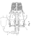
- Fig. 1 is cross-sectional view of an inflation system including an aspirator incorporating features of the present invention shown in its stowed condition;
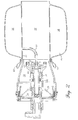
- Fig. 2 is the aspirator of Fig. 1 shown in its deployed condition
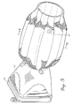
- Fig. 3 is a perspective view of the aspirator of Fig. 1 in its deployed condition
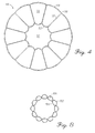
- Fig. 4 is a cross-sectional view of the aspirator of Fig. 3 taken along line 4, 4;
- Fig. 5 is a cross-sectional view of an alternative embodiment of an aspirator incorporating features of the present invention.
- Fig. 6 is another alternative embodiment of an aspirator incorporating features of the present invention.
- Fig. 7 is yet another alternative embodiment of an aspirator incorporating features of the present invention.
- Fig. 8 is a cross-sectional view of yet another alternative embodiment.
- an inflation system 10 for inflating an inflatable device 12 comprises an inflation source 14, which may be a pressure vessel containing gas under a relatively high pressure, a pyrotechnic gas generator, a hybrid inflator comprising a pyrotechnic gas generator and a stored compressed gas or any other suitable source of inflation gas.
- Inflation source 14 is fluidically connected to inlet port 16 of aspirator 20 via a control valve shown schematically as reference 18 in Fig. 1 .
- Aspirator 20 comprises a housing 22, which in the illustrative embodiment comprises an upstream portion 24 of substantially rectangular cross-section converging to a downstream portion 26 of substantially circular cross-section.
- Upstream portion 24 of housing 22 includes a plurality of check valves 28 comprising rectangular flaps that are hinged to allow the atmospheric air to flow into the interior volume 30 of housing 22 when the pressure in interior volume 30 is sub-atmospheric.
- Check valves 28 are biased toward the closed position to prevent air escaping interior volume 30 of housing 22 when the pressure in interior volume 30 is equal to or greater than atmospheric pressure.
- Aspirator housing 22 can be constructed of any suitable material such as metal, plastic or the like, but in the illustrative example of Fig. 1 , housing 22 is formed of a reinforced plastic, In typical installations, housing 22 is mounted to inflatable device 12 so that all or a substantial portion of housing 22 extends into the inflatable device 12 through an opening in the inflatable device 12 for that purpose.
- Aspirator 20 may optionally be equipped with a slide valve 32, which moves away from check valves 28 to allow them to open when the pressure in channel 34 is sufficiently high.
- spring 36 urges slide valve 32 against check valves 28 to lock them in their closed positions.
- Aspirator 20 further comprises a nozzle assembly 40 comprising a plurality of individual nozzles 42 for directing high velocity jets of gas into the intake end 44 of aspirator barrel 46.
- Aspirator barrel 46 comprises a plurality of tubular support members 48, which in the illustrative embodiment are formed by attaching ( e.g ., stitching together or bonding) an outer sleeve 50 and an inner sleeve 52 to with a plurality of webs 56 which run in a longitudinal direction relative to a flow of gas through the inner lumen 54 of aspirator barrel 46.
- Outer sleeve 50, inner sleeve 52 and webs 56 of aspirator barrel 46 are preferably fabricated from an air impervious material such a lightweight fabric that has been coated with an elastomer such as rubber or urethane.
- the various parts of the aspirator barrel 46 form a unitary composite structure capable of maintaining its shape during operation.
- the entire structure of the aspirator barrel 46 is preferable formed such that all of the chambers 56 comprising the structure are interconnected pneumatically, such that a single pressurized gas source may be utilized for its deployment.
- Aspirator barrel 46 further comprises a conduit 58 which interconnects the chambers 56 of tubular support members 48 to nozzle assembly 40.
- Conduit 58 preferably comprises an off-the-shelf reinforced elastomeric high pressure hose, but may be made of any suitable material capable of withstanding inflation pressures present in nozzle assembly 40.
- conduit 58 may comprise a reinforced fabric sleeve coated with an elastomer similar in construction to the tubular support members 48.
- Aspirator barrel 46 is secured to housing 22 by means of a plurality of fabric loops 60 which are secured to the downstream portion 26 of housing 22.
- aspirator barrel 46 may be attached to housing 22 by means of a dedicated flange similar in construction to flange 62 which secures housing 22 to the inflatable device 12.
- high pressure gas from inflation source 14 enters the aspirator through inlet port 16 and exits through nozzles 42 of nozzle assembly 40 into intake end 44 of aspirator barrel 46. Simultaneously, high pressure gas from inflation source 14 flows from nozzle assembly 40 through conduit 58 into chambers 56 of aspirator barrel 46 causing aspirator barrel 46 to deploy from its stowed condition as shown in Fig. 1 to its deployed condition as shown in Fig. 2 . Because aspirator barrel 46 is exposed to the full inflation pressure present in nozzle assembly 40, aspirator barrel 46 may be equipped with one or more pressure relief valves 62 to prevent overpressurization and consequential distortion or rupturing of aspirator barrel 46 .
- the large ratio of nozzle periphery to cross-sectional area of nozzles 42 is sufficient to induce a flow of ambient air from interior volume 30 of housing 22 into inner lumen 54 of aspirator barrel 46. This induced airflow will in turn cause the pressure in interior volume 30 and at least a portion of inner lumen 54 to drop below atmospheric pressure, The pressure of atmospheric air on the check valves 28 causes them to swing inwardly toward an open position, permitting the atmospheric air to enter housing 22 to become entrained with the high velocity flow of gas exiting nozzles 42.
- the multiple chamber structure of aspirator barrel 46 enables it to be substantially rigid and therefore to maintain the shape of interior lumen 54 notwithstanding the sub-atmospheric pressure and pressure fluctuation within interior lumen 54.
- the ratio of the length of the interior lumen 54 to its effective diameter is at least 1.0 preferably at least 1.5 and is typically between 1.5 and 3.0 for a maximum efficiency.
- "effective diameter" is the diameter of a circle of equal flow area, i,e ., the cross-sectional area of interior lumen 54 divided by ⁇ ).
- aspirator barrel 46 in its deployed condition is substantially rigid in that it is capable of maintaining the shape of inner lumen 54 in spite of sub-atmospheric pressure and/or pressure fluctuations in inner lumen 54 that would cause a flexible conduit to collapse and/or flutter, thus stalling the air stream and reducing the aspirator efficiency.
- the jet stream flowing from the nozzles will have sufficient velocity to induce a flow of atmospheric air past check valves 28.
- the pressure at the source is reduced and the velocity of the gas exiting the nozzles falls, back pressure from the inflatable device 12 will cause the check valves 28 to close. Since the pressure of the inflation source 14 will still be above the pressure in the inflatable device 12, gas will continue to flow from nozzles 42 to increase the pressure in the inflatable device without the addition of any further entrained atmospheric air.
- the final pressure of the inflatable device then may be limited by providing various pressure relief valves or other devices to limit the final inflation pressure.
- Fligs. 1-4 contemplate inflatable tubular support members 48 which are longitudinal with respect to a flow of gas through inner lumen 54, the present invention is not limited to a longitudinal support structure.
- An alternative embodiment as shown in Fig. 5 contemplates a plurality of torroidal support members 68 supporting an inner sleeve forming the outer wall of lumen 74.
- Torroidal support members 68 may comprise a plurality of individual torroidal support members interconnected by a common septum or may constitute a single helical torroid fluidically connected via conduit 58 to inflation source 14. Additionally, as shown in Fig.
- the present invention is not limited to a collapsible aspirator barrel fabricated in entirely of fabric but may comprise a plurality of rigid supports such as hoops 82 formed of any suitable rigid material such as metal or plastic in combination with one or more fabric sleeves 84, 86 forming a structure that is inflated to expand from a stowed, collapsed condition to a deployed condition having sufficient rigidity to maintain the shape of interior lumen 88 as hereinbefore described.
- any source of high pressure inflation gas may be utilized without departing from the present invention, for example, as shown in Fig. 7 , an external conduit 92 leading directly to inflation source 14 may be incorporated in lieu of conduit 58 for providing pressurized gas for inflating aspirator barrel 94.
- Fig. 4 comprises a plurality of tubular members formed by stitching a plurality of webs between an inner and outer sleeve, as shown in FIG. 8
- outer sleeve 102 may be stitched directly to inner sleeve 104 to form a plurality of longitudinal tubular members 106 without departing from the scope of the present invention. Accordingly, it is intended that the invention should be limited only to the extent required by the appended claims and the rules and principles of applicable law.
- the terms "substantially” or “generally” when used with mathematical concepts or measurements mean within ⁇ 10 degrees of angle or within 10 percent of the measurement, whichever is greater.
Landscapes
- Engineering & Computer Science (AREA)
- Physics & Mathematics (AREA)
- Fluid Mechanics (AREA)
- Mechanical Engineering (AREA)
- General Engineering & Computer Science (AREA)
- Business, Economics & Management (AREA)
- Emergency Management (AREA)
- Aviation & Aerospace Engineering (AREA)
- Jet Pumps And Other Pumps (AREA)
Abstract
Description
- This invention relates generally to apparatus for inflating devices, in particular to apparatus for inflating aircraft emergency evacuation slides and rafts.
- Aircraft emergency evacuation slides, emergency life rafts and similar devices are typically stored in a packed configuration occupying as little space as possible for long periods of time. When called upon for use, these inflatable devices are typically inflated to a relatively low pressure, on the order of 2-3 psig for conventional aircraft evacuation slides up to approximately 7-8 psig for advanced high pressure lightweight evacuation slides. The requirement that the inflatable device in its packed condition occupy a minimum volume dictates that the inflation source comprise a volume of gas stored in a high pressure container, a pyrotechnic gas generator, or a hybrid inflator comprising a pyrotechnic gas generator in combination with a quantity of gas stored at high pressure.
- Because the aforementioned high pressure inflation sources exhaust a volume of gas at a pressure substantially higher than the inflation pressure of the inflatable device, it is common to use an aspirator to draw atmospheric air into the inflatable device during inflation to augment the high pressure gas flowing into the inflatable device. In the operation of an aspirator, one or more nozzles act as gas injectors, injecting a jet stream of gas at high velocity into the inlet end of an aspirator barrel. The flow of air entering the aspirator barrel reduces the pressure at the inlet end to below atmospheric pressure. Atmospheric air, therefore, enters the aspirator body to be entrained with the jet stream entering the aspirator barrel. The outlet of the aspirator barrel communicates with the interior volume of the inflatable device so that jet stream and the entrained air collectively make up the volume of gas filling the inflatable device.
- Because the aspirator barrel must be capable of operating at sub-atmospheric pressure without collapsing, aspirators are conventionally equipped with rigid aspirator barrels. Although a rigid aspirator barrel adequately performs the function of entraining atmospheric air into the jet stream produced by the injector nozzle(s) a rigid aspirator barrel adds significant weight and storage volume to the inflatable device. USPN 5,002,465 to Lagen et al. and USPN 6,071,084 to Wass et al, suggest aspirators having telescoping aspirator barrels. Although a telescoping aspirator barrel reduces the storage volume of the aspirator to some extent, a telescoping aspirator barrel typically collapses by only about 20% or less and, therefore, 80% or more of the length of the rigid aspirator barrel remains to be stored in the limited volume for storage of the inflatable device.
- The present invention comprises an aspirator having a flexible, collapsible aspirator barrel. According to an embodiment of the invention, the collapsible aspirator barrel comprises an inflatable support member that is inflated to form a substantially rigid tube. According to one illustrative embodiment, the inflatable support member receives a flow of high pressure air directly from the injector nozzle assembly. According to another illustrative embodiment, the collapsible aspirator barrel receives a flow of high pressure gas directly from the high pressure inflation source. Because the aspirator barrel of the present invention is collapsible, the present invention occupies significantly less space when stored than an equivalent aspirator with a rigid or a telescoping aspirator barrel.
- The present invention will be better understood from a reading of the following detailed description, taken in conjunction with the accompanying drawing figures in which like references designate like elements and, in which:
-
Fig. 1 is cross-sectional view of an inflation system including an aspirator incorporating features of the present invention shown in its stowed condition; -
Fig. 2 is the aspirator ofFig. 1 shown in its deployed condition; -
Fig. 3 is a perspective view of the aspirator ofFig. 1 in its deployed condition; -
Fig. 4 is a cross-sectional view of the aspirator ofFig. 3 taken along line 4, 4; -
Fig. 5 is a cross-sectional view of an alternative embodiment of an aspirator incorporating features of the present invention; -
Fig. 6 is another alternative embodiment of an aspirator incorporating features of the present invention; and -
Fig. 7 is yet another alternative embodiment of an aspirator incorporating features of the present invention. -
Fig. 8 is a cross-sectional view of yet another alternative embodiment. - The drawing figures are intended to illustrate the general manner of construction and are not necessarily to scale, In the detailed description and in the drawing figures, specific illustrative examples are shown and herein described in detail. It should be understood, however, that the drawing figures and detailed description are not intended to limit the invention to the particular form disclosed, but are merely illustrative and intended to teach one of ordinary skill how to make and/or use the invention claimed herein and for setting forth the best mode for carrying out the invention.
- With reference to
Figs. 1-4 , aninflation system 10 for inflating aninflatable device 12 comprises aninflation source 14, which may be a pressure vessel containing gas under a relatively high pressure, a pyrotechnic gas generator, a hybrid inflator comprising a pyrotechnic gas generator and a stored compressed gas or any other suitable source of inflation gas.Inflation source 14 is fluidically connected toinlet port 16 ofaspirator 20 via a control valve shown schematically asreference 18 inFig. 1 . -
Aspirator 20 comprises ahousing 22, which in the illustrative embodiment comprises anupstream portion 24 of substantially rectangular cross-section converging to adownstream portion 26 of substantially circular cross-section.Upstream portion 24 ofhousing 22 includes a plurality ofcheck valves 28 comprising rectangular flaps that are hinged to allow the atmospheric air to flow into theinterior volume 30 ofhousing 22 when the pressure ininterior volume 30 is sub-atmospheric.Check valves 28 are biased toward the closed position to prevent air escapinginterior volume 30 ofhousing 22 when the pressure ininterior volume 30 is equal to or greater than atmospheric pressure. -
Aspirator housing 22 can be constructed of any suitable material such as metal, plastic or the like, but in the illustrative example ofFig. 1 ,housing 22 is formed of a reinforced plastic, In typical installations,housing 22 is mounted toinflatable device 12 so that all or a substantial portion ofhousing 22 extends into theinflatable device 12 through an opening in theinflatable device 12 for that purpose. - Aspirator 20 may optionally be equipped with a
slide valve 32, which moves away fromcheck valves 28 to allow them to open when the pressure inchannel 34 is sufficiently high. When pressure inchannel 34 falls below a pre-determined threshold indicating theinflatable device 12 is substantially near its full inflation pressure,spring 36urges slide valve 32 againstcheck valves 28 to lock them in their closed positions. -
Aspirator 20 further comprises anozzle assembly 40 comprising a plurality ofindividual nozzles 42 for directing high velocity jets of gas into theintake end 44 ofaspirator barrel 46.Aspirator barrel 46 comprises a plurality oftubular support members 48, which in the illustrative embodiment are formed by attaching (e.g., stitching together or bonding) anouter sleeve 50 and aninner sleeve 52 to with a plurality ofwebs 56 which run in a longitudinal direction relative to a flow of gas through theinner lumen 54 ofaspirator barrel 46. -
Outer sleeve 50,inner sleeve 52 andwebs 56 ofaspirator barrel 46 are preferably fabricated from an air impervious material such a lightweight fabric that has been coated with an elastomer such as rubber or urethane. The various parts of theaspirator barrel 46 form a unitary composite structure capable of maintaining its shape during operation. The entire structure of theaspirator barrel 46 is preferable formed such that all of thechambers 56 comprising the structure are interconnected pneumatically, such that a single pressurized gas source may be utilized for its deployment. -
Aspirator barrel 46 further comprises aconduit 58 which interconnects thechambers 56 oftubular support members 48 tonozzle assembly 40.Conduit 58 preferably comprises an off-the-shelf reinforced elastomeric high pressure hose, but may be made of any suitable material capable of withstanding inflation pressures present innozzle assembly 40. For example,conduit 58 may comprise a reinforced fabric sleeve coated with an elastomer similar in construction to thetubular support members 48.Aspirator barrel 46 is secured to housing 22 by means of a plurality offabric loops 60 which are secured to thedownstream portion 26 ofhousing 22. Alternatively,aspirator barrel 46 may be attached tohousing 22 by means of a dedicated flange similar in construction toflange 62 which secureshousing 22 to theinflatable device 12. - In operation, high pressure gas from
inflation source 14 enters the aspirator throughinlet port 16 and exits throughnozzles 42 ofnozzle assembly 40 intointake end 44 ofaspirator barrel 46. Simultaneously, high pressure gas frominflation source 14 flows fromnozzle assembly 40 throughconduit 58 intochambers 56 ofaspirator barrel 46 causingaspirator barrel 46 to deploy from its stowed condition as shown inFig. 1 to its deployed condition as shown inFig. 2 . Becauseaspirator barrel 46 is exposed to the full inflation pressure present innozzle assembly 40,aspirator barrel 46 may be equipped with one or morepressure relief valves 62 to prevent overpressurization and consequential distortion or rupturing ofaspirator barrel 46. - The large ratio of nozzle periphery to cross-sectional area of
nozzles 42 is sufficient to induce a flow of ambient air frominterior volume 30 ofhousing 22 intoinner lumen 54 ofaspirator barrel 46. This induced airflow will in turn cause the pressure ininterior volume 30 and at least a portion ofinner lumen 54 to drop below atmospheric pressure, The pressure of atmospheric air on thecheck valves 28 causes them to swing inwardly toward an open position, permitting the atmospheric air to enterhousing 22 to become entrained with the high velocity flow ofgas exiting nozzles 42. - The multiple chamber structure of
aspirator barrel 46 enables it to be substantially rigid and therefore to maintain the shape ofinterior lumen 54 notwithstanding the sub-atmospheric pressure and pressure fluctuation withininterior lumen 54. As shown inFig. 2 , in order for the induced flow of air to be sufficient to entrain substantial atmospheric air, the ratio of the length of theinterior lumen 54 to its effective diameter is at least 1.0 preferably at least 1.5 and is typically between 1.5 and 3.0 for a maximum efficiency. (Becauseinterior lumen 54 is not perfectly cylindrical, as used herein, "effective diameter" is the diameter of a circle of equal flow area, i,e., the cross-sectional area ofinterior lumen 54 divided by π). As noted herein,aspirator barrel 46 in its deployed condition is substantially rigid in that it is capable of maintaining the shape ofinner lumen 54 in spite of sub-atmospheric pressure and/or pressure fluctuations ininner lumen 54 that would cause a flexible conduit to collapse and/or flutter, thus stalling the air stream and reducing the aspirator efficiency. - During the major portion of the operation of
aspirator 20, the jet stream flowing from the nozzles will have sufficient velocity to induce a flow of atmospheric airpast check valves 28. When, however, the pressure at the source is reduced and the velocity of the gas exiting the nozzles falls, back pressure from theinflatable device 12 will cause thecheck valves 28 to close. Since the pressure of theinflation source 14 will still be above the pressure in theinflatable device 12, gas will continue to flow fromnozzles 42 to increase the pressure in the inflatable device without the addition of any further entrained atmospheric air. The final pressure of the inflatable device then may be limited by providing various pressure relief valves or other devices to limit the final inflation pressure. - Although the illustrative embodiment of Fligs. 1-4 contemplate inflatable
tubular support members 48 which are longitudinal with respect to a flow of gas throughinner lumen 54, the present invention is not limited to a longitudinal support structure. An alternative embodiment as shown inFig. 5 contemplates a plurality oftorroidal support members 68 supporting an inner sleeve forming the outer wall oflumen 74.Torroidal support members 68 may comprise a plurality of individual torroidal support members interconnected by a common septum or may constitute a single helical torroid fluidically connected viaconduit 58 toinflation source 14. Additionally, as shown inFig. 6 the present invention is not limited to a collapsible aspirator barrel fabricated in entirely of fabric but may comprise a plurality of rigid supports such ashoops 82 formed of any suitable rigid material such as metal or plastic in combination with one ormore fabric sleeves aspirator barrel 46 through aconduit 58 emanating fromnozzle assembly 40, any source of high pressure inflation gas may be utilized without departing from the present invention, for example, as shown inFig. 7 , an external conduit 92 leading directly toinflation source 14 may be incorporated in lieu ofconduit 58 for providing pressurized gas for inflatingaspirator barrel 94. - Although certain illustrative embodiments and methods have been disclosed herein, it will be apparent from the foregoing disclosure to those skilled in the art that variations and modifications of such embodiments and methods may be made without departing from the invention. For example, although the illustrative embodiment of
Fig. 4 comprises a plurality of tubular members formed by stitching a plurality of webs between an inner and outer sleeve, as shown inFIG. 8 ,outer sleeve 102 may be stitched directly toinner sleeve 104 to form a plurality of longitudinaltubular members 106 without departing from the scope of the present invention. Accordingly, it is intended that the invention should be limited only to the extent required by the appended claims and the rules and principles of applicable law. Additionally, as used herein, unless otherwise specifically defined, the terms "substantially" or "generally" when used with mathematical concepts or measurements mean within ± 10 degrees of angle or within 10 percent of the measurement, whichever is greater. - Further embodiments of the present invention are the following:
- 1. In combination with an inflatable object such as an aircraft evacuation slide or raft, an aspirator for inflating the inflatable object comprising:
- a housing having an intake end and an exhaust end, the intake end including a check valve being moveable from an open position for admitting entrance of atmospheric air into said housing to a closed position for preventing air from escaping said housing;
- a collapsible aspirator barrel comprising an inflatable support member which, when inflated, expands to form a substantially rigid tube having an inner lumen with a first end operatively attached to the exhaust end of said housing and a second end operatively attached to an inlet port of the inflatable object, said collapsible aspirator barrel further comprising an inlet port adapted to receive a source of pressurized gas for inflating the inflatable support member; and
- a nozzle assembly disposed within said housing proximal the exhaust end of said housing, said nozzle assembly comprising an inlet capable of receiving a source of pressurized gas and an outlet comprising a nozzle exit directed into the first end of the inner lumen of said collapsible barrel.
- 2. Embodiment 1, wherein said inflatable support-member comprises a plurality of elastomer-coated fabric tubular members.
- 3. Embodiment 1, wherein the inflatable member is an aircraft evacuation slide.
Claims (15)
- In combination with an inflatable object (12) such as an aircraft evacuation slide or raft, an aspirator (20) for inflating the inflatable object (12) comprising:a housing (22) having an intake end (24) and an exhaust end (26), the intake end including a check valve (28) being moveable from an open position for admitting entrance of atmospheric air into said housing to a closed position for preventing air from escaping said housing;a collapsible aspirator barrel (46) comprising an inflatable support member which, when inflated, expands to form a substantially rigid tube having an inner lumen (54) with a first end (44) operatively attached to the exhaust end of said housing and a second end operatively attached to an inlet port of the inflatable object, said collapsible aspirator barrel (45) further comprising an inlet port (58) adapted to receive a source (14) of pressurized gas for inflating the inflatable support member; anda nozzle assembly (40) disposed within said housing (22) proximal the exhaust end (26) of said housing, said nozzle assembly (40) comprising an inlet capable of receiving a source (14) of pressurized gas and an outlet comprising a nozzle exit directed into the first end of the inner lumen (54) of said collapsible barrel (46).
- The aspirator of claim 1, wherein:the inner lumen (54) of said collapsible aspirator barrel (46) has substantially the same cross sectional area as the exhaust end (26) of said housing (22).
- The aspirator of claim 1 or 2, wherein:said housing (22) comprises a rigid structure formed of a reinforced plastic.
- The aspirator of any of the preceding claims, wherein:the inner lumen (54) of said collapsible aspirator barrel (46) has a length to effective diameter ratio of at least 1.0.
- The aspirator of claim 4, wherein:the inner lumen (54) of said collapsible aspirator barrel (46) has a length to effective diameter ratio of at between 1.5 and 3.0.
- The aspirator of any of the preceding claims, wherein:said inflatable support member comprises a plurality of tubular members (48).
- The aspirator of claim 6, wherein:said inflatable support member comprises a plurality of tubular members (48) arranged longitudinally with respect to a flow of fluid through the inner lumen (54) of said collapsible aspirator barrel (46) from said housing (22) into the inflatable object (12).
- The aspirator of any of the preceding claims, wherein:the inner lumen (54) of said collapsible aspirator barrel (46) is capable of remaining open with sub-atmospheric pressure within said inner lumen.
- The aspirator of any of the preceding claims, wherein:the inlet port (58) of said collapsible aspirator barrel (46) is fluidically connected to said nozzle assembly.
- The aspirator of any of the preceding claims, wherein:the inlet port (58) of said collapsible aspirator barrel (46) and said nozzle assembly (40) are fluidically connected to a common source (14) of pressurized gas.
- The aspirator of any of the preceding claims, wherein:the inlet port (58) of said collapsible aspirator barrel (46) is located within the inner lumen (54) of said collapsible aspirator barrel (46).
- An aircraft evacuation slide system comprising:an inflatable evacuation slide comprising a plurality of inflatable tubular members supporting a slide surface;an aspirator (20) for inflating the inflatable evacuation slide, said aspirator comprising a housing (22) having an intake end (24) and an exhaust end (26), the intake end (24) including a check valve (28) being moveable from an open position for admitting entrance of atmospheric air into the housing to a closed position for preventing air from escaping the housing;a collapsible aspirator barrel (46) comprising an inflatable support member which, when inflated, expands to form a substantially rigid tube having an inner lumen (54) with a first end (44) operatively attached to the exhaust end (26) of said housing (22) and a second end operatively attached to an inlet port of the inflatable evacuation slide, said collapsible aspirator barrel further comprising an inlet port (58) adapted to receive a source (14) of pressurized gas for inflating the inflatable support member; anda nozzle assembly (40) disposed within said housing proximal the exhaust end (26) of said housing (22), said nozzle assembly (40) comprising an inlet capable of receiving a source of pressurized gas and an outlet comprising a nozzle exit directed into the first end of the inner lumen of said collapsible barrel.
- The aircraft evacuation slide system of claim 12, wherein:said inflatable support member comprises a plurality of elastomer-coated fabric tubular members (48) arranged longitudinally with respect to a flow of fluid through the inner lumen (54) of said collapsible aspirator barrel (46) from said housing (22) into said inflatable evacuation slide.
- The aircraft evacuation slide system of claim 12 or 13, wherein:the inner lumen (54) of said collapsible aspirator barrel (46) has substantially the same cross sectional area as the exhaust end of the housing.
- The aircraft evacuation slide system of claims 12 to 14, wherein:the inner lumen (54) of said collapsible aspirator barrel (46) has a length to effective diameter ratio of at least 1.5.
Applications Claiming Priority (1)
| Application Number | Priority Date | Filing Date | Title |
|---|---|---|---|
| US12/425,145 US8066493B2 (en) | 2009-04-16 | 2009-04-16 | Inflation aspirator with collapsible barrel |
Publications (3)
| Publication Number | Publication Date |
|---|---|
| EP2243963A2 true EP2243963A2 (en) | 2010-10-27 |
| EP2243963A3 EP2243963A3 (en) | 2018-03-28 |
| EP2243963B1 EP2243963B1 (en) | 2019-05-22 |
Family
ID=42396509
Family Applications (1)
| Application Number | Title | Priority Date | Filing Date |
|---|---|---|---|
| EP10156477.1A Active EP2243963B1 (en) | 2009-04-16 | 2010-03-15 | Inflation aspirator with collapsible barrel |
Country Status (2)
| Country | Link |
|---|---|
| US (1) | US8066493B2 (en) |
| EP (1) | EP2243963B1 (en) |
Cited By (2)
| Publication number | Priority date | Publication date | Assignee | Title |
|---|---|---|---|---|
| EP3118117A1 (en) * | 2015-07-17 | 2017-01-18 | Goodrich Corporation | Collapsible/ extendable aspirator system |
| CN107521704A (en) * | 2017-07-31 | 2017-12-29 | 凯迈(洛阳)气源有限公司 | A kind of induction apparatus and its damper assemblies |
Families Citing this family (21)
| Publication number | Priority date | Publication date | Assignee | Title |
|---|---|---|---|---|
| US10260530B2 (en) * | 2014-10-10 | 2019-04-16 | Circor Aerospace, Inc. | Aspirator and method of fabricating |
| US10167087B2 (en) | 2016-04-15 | 2019-01-01 | Goodrich Corporation | Collapsible inflatable aspirator system |
| US10549861B2 (en) * | 2016-11-14 | 2020-02-04 | Goodrich Corporation | Redundant layer for inflatable evacuation component |
| US11555638B2 (en) * | 2016-11-30 | 2023-01-17 | Dwyer Instruments, Llc | Venturi vacuum drawback assemblies and dual orifice venturi valve assemblies |
| US10641406B2 (en) * | 2016-11-30 | 2020-05-05 | Universal Flow Monitors, Inc. | Venturi vacuum drawback assemblies and dual orifice venturi valve assemblies |
| US10683095B2 (en) * | 2016-12-02 | 2020-06-16 | Goodrich Corporation | Collapsible aspirator barrel |
| US11174878B2 (en) * | 2017-01-13 | 2021-11-16 | Goodrich Corporation | Aspirator system |
| US11077957B2 (en) * | 2017-01-23 | 2021-08-03 | Textron Innovations Inc. | Selectable barrier filtration system |
| USD839387S1 (en) | 2017-07-06 | 2019-01-29 | Altevac Llc | Aspirator nozzle |
| US11333174B2 (en) | 2017-07-06 | 2022-05-17 | Altevac, Llc | High efficiency aspirator for inflatable emergency slides |
| US10562043B2 (en) | 2017-09-22 | 2020-02-18 | Goodrich Corporation | Telescoping aspirator system |
| US11035483B2 (en) | 2018-02-07 | 2021-06-15 | Universal Flow Monitors, Inc. | Dual orifice venturi vacuum drawback assemblies having air breather check valve |
| US10718356B2 (en) * | 2018-02-12 | 2020-07-21 | Goodrich Corporation | Aspirator inflatable diffuser |
| US10704568B2 (en) | 2018-02-15 | 2020-07-07 | Goodrich Corporation | Aspirator integrated pressure relief valve and vent valve assembly for an inflation system |
| US10876644B2 (en) * | 2018-05-22 | 2020-12-29 | Goodrich Corporation | Aspirator system pressure relief mechanism |
| US10823300B2 (en) * | 2018-10-18 | 2020-11-03 | Goodrich Corporation | Aspirator pressure relief valve with relief control unit |
| US11143208B2 (en) * | 2018-12-17 | 2021-10-12 | Goodrich Corporation | Aspirators for evacuation assemblies |
| US11198514B2 (en) * | 2019-08-19 | 2021-12-14 | Goodrich Corporation | Aspirator with pressure relief flaps |
| US11560905B2 (en) | 2019-12-13 | 2023-01-24 | Goodrich Corporation | Multistage aspirator for inflatable assemblies |
| US11591095B2 (en) * | 2020-03-20 | 2023-02-28 | Goodrich Corporation | Pressure relief valve with deflecting disks for inflatable |
| CN219366257U (en) * | 2022-12-26 | 2023-07-18 | 东莞市楷模家居用品制造有限公司 | Folding inflatable independent cylinder mechanism |
Family Cites Families (10)
| Publication number | Priority date | Publication date | Assignee | Title |
|---|---|---|---|---|
| US2772829A (en) | 1955-05-02 | 1956-12-04 | Garrett Corp | Inflation aspirator |
| US3042290A (en) | 1960-07-18 | 1962-07-03 | Garrett Corp | Inflation aspirator lock |
| US3468472A (en) * | 1967-09-15 | 1969-09-23 | Global Systems | Flow augmented nozzle |
| US3572974A (en) * | 1969-04-04 | 1971-03-30 | Sargent Industries | Aspirator apparatus for bag inflation systems |
| US3771913A (en) * | 1971-05-18 | 1973-11-13 | Susquehanna Corp | Aspirator |
| US4368009A (en) | 1980-08-15 | 1983-01-11 | The B. F. Goodrich Company | Aspirator |
| US4412568A (en) | 1981-08-24 | 1983-11-01 | Otto K. Henke | Fill valve |
| US5002465A (en) | 1989-10-12 | 1991-03-26 | The Boeing Company | Off-on control for an inflation aspirator |
| US6071084A (en) | 1995-11-14 | 2000-06-06 | Wass; Lloyd G. | Aspirator |
| US7744122B2 (en) | 1995-12-12 | 2010-06-29 | Automotive Technologies International, Inc. | Driver side aspirated airbags |
-
2009
- 2009-04-16 US US12/425,145 patent/US8066493B2/en active Active
-
2010
- 2010-03-15 EP EP10156477.1A patent/EP2243963B1/en active Active
Non-Patent Citations (1)
| Title |
|---|
| None |
Cited By (4)
| Publication number | Priority date | Publication date | Assignee | Title |
|---|---|---|---|---|
| EP3118117A1 (en) * | 2015-07-17 | 2017-01-18 | Goodrich Corporation | Collapsible/ extendable aspirator system |
| US9863442B2 (en) | 2015-07-17 | 2018-01-09 | Goodrich Corporation | Collapsible/extendable aspirator system |
| US10619651B2 (en) | 2015-07-17 | 2020-04-14 | Goodrich Corporation | Collapsible/ extendable aspirator system |
| CN107521704A (en) * | 2017-07-31 | 2017-12-29 | 凯迈(洛阳)气源有限公司 | A kind of induction apparatus and its damper assemblies |
Also Published As
| Publication number | Publication date |
|---|---|
| US8066493B2 (en) | 2011-11-29 |
| US20100266424A1 (en) | 2010-10-21 |
| EP2243963B1 (en) | 2019-05-22 |
| EP2243963A3 (en) | 2018-03-28 |
Similar Documents
| Publication | Publication Date | Title |
|---|---|---|
| US8066493B2 (en) | Inflation aspirator with collapsible barrel | |
| US3460746A (en) | Two-stage inflation aspirator | |
| EP3242040B1 (en) | Collapsible inflatable aspirator system | |
| ES2804274T3 (en) | Ventilation method of a dynamic air channel and vehicle and environmental control device to carry out this method | |
| US4715417A (en) | Aircraft fuel tank | |
| US20190112059A1 (en) | Evacuation slide with aspirator retention strap | |
| KR20160127408A (en) | apparatus for preventing subversion of boat | |
| US11007386B2 (en) | Aspirator for air flow amplification | |
| CN111225852B (en) | Inflators for emergency aircraft buoyancy | |
| US2421679A (en) | Lifesaving boat | |
| EP3348484B1 (en) | Aspirator system | |
| EP3345835B1 (en) | Aspirator | |
| US3771913A (en) | Aspirator | |
| US20200239115A1 (en) | Inline aspirator for inflatable assemblies | |
| US20190186504A1 (en) | Aspirator system | |
| US10718356B2 (en) | Aspirator inflatable diffuser | |
| EP0039466A1 (en) | Escape slide with multiple inflation units | |
| CN209870699U (en) | Vehicle-mounted inflatable life buoy | |
| EP3899332B1 (en) | Valve for inflating and deflating an inflatable element | |
| JP2015218682A (en) | Windmill equipment | |
| US11143208B2 (en) | Aspirators for evacuation assemblies | |
| CN108146640B (en) | System for inflating a flotation device, aircraft with an evacuation system and evacuation system | |
| US10640220B2 (en) | Anti-kiting device | |
| US10994850B2 (en) | Aspirators for evacuation assemblies | |
| EP3321182A1 (en) | Redundant layer for inflatable evacuation component |
Legal Events
| Date | Code | Title | Description |
|---|---|---|---|
| PUAI | Public reference made under article 153(3) epc to a published international application that has entered the european phase |
Free format text: ORIGINAL CODE: 0009012 |
|
| AK | Designated contracting states |
Kind code of ref document: A2 Designated state(s): AT BE BG CH CY CZ DE DK EE ES FI FR GB GR HR HU IE IS IT LI LT LU LV MC MK MT NL NO PL PT RO SE SI SK SM TR |
|
| AX | Request for extension of the european patent |
Extension state: AL BA ME RS |
|
| 17P | Request for examination filed |
Effective date: 20121004 |
|
| PUAL | Search report despatched |
Free format text: ORIGINAL CODE: 0009013 |
|
| AK | Designated contracting states |
Kind code of ref document: A3 Designated state(s): AT BE BG CH CY CZ DE DK EE ES FI FR GB GR HR HU IE IS IT LI LT LU LV MC MK MT NL NO PL PT RO SE SI SK SM TR |
|
| AX | Request for extension of the european patent |
Extension state: AL BA ME RS |
|
| RIC1 | Information provided on ipc code assigned before grant |
Ipc: F04F 5/54 20060101ALI20180221BHEP Ipc: F04F 5/14 20060101ALI20180221BHEP Ipc: B64D 25/14 20060101ALI20180221BHEP Ipc: F04F 5/46 20060101AFI20180221BHEP |
|
| GRAP | Despatch of communication of intention to grant a patent |
Free format text: ORIGINAL CODE: EPIDOSNIGR1 |
|
| STAA | Information on the status of an ep patent application or granted ep patent |
Free format text: STATUS: GRANT OF PATENT IS INTENDED |
|
| RIC1 | Information provided on ipc code assigned before grant |
Ipc: F04F 5/46 20060101AFI20181106BHEP Ipc: F04F 5/14 20060101ALI20181106BHEP Ipc: F04F 5/54 20060101ALI20181106BHEP Ipc: B64D 25/14 20060101ALI20181106BHEP |
|
| INTG | Intention to grant announced |
Effective date: 20181203 |
|
| GRAS | Grant fee paid |
Free format text: ORIGINAL CODE: EPIDOSNIGR3 |
|
| GRAA | (expected) grant |
Free format text: ORIGINAL CODE: 0009210 |
|
| STAA | Information on the status of an ep patent application or granted ep patent |
Free format text: STATUS: THE PATENT HAS BEEN GRANTED |
|
| AK | Designated contracting states |
Kind code of ref document: B1 Designated state(s): AT BE BG CH CY CZ DE DK EE ES FI FR GB GR HR HU IE IS IT LI LT LU LV MC MK MT NL NO PL PT RO SE SI SK SM TR |
|
| REG | Reference to a national code |
Ref country code: GB Ref legal event code: FG4D |
|
| REG | Reference to a national code |
Ref country code: CH Ref legal event code: EP |
|
| REG | Reference to a national code |
Ref country code: IE Ref legal event code: FG4D |
|
| REG | Reference to a national code |
Ref country code: DE Ref legal event code: R096 Ref document number: 602010059010 Country of ref document: DE |
|
| REG | Reference to a national code |
Ref country code: AT Ref legal event code: REF Ref document number: 1136459 Country of ref document: AT Kind code of ref document: T Effective date: 20190615 |
|
| REG | Reference to a national code |
Ref country code: NL Ref legal event code: MP Effective date: 20190522 |
|
| REG | Reference to a national code |
Ref country code: LT Ref legal event code: MG4D |
|
| PG25 | Lapsed in a contracting state [announced via postgrant information from national office to epo] |
Ref country code: PT Free format text: LAPSE BECAUSE OF FAILURE TO SUBMIT A TRANSLATION OF THE DESCRIPTION OR TO PAY THE FEE WITHIN THE PRESCRIBED TIME-LIMIT Effective date: 20190922 Ref country code: NL Free format text: LAPSE BECAUSE OF FAILURE TO SUBMIT A TRANSLATION OF THE DESCRIPTION OR TO PAY THE FEE WITHIN THE PRESCRIBED TIME-LIMIT Effective date: 20190522 Ref country code: ES Free format text: LAPSE BECAUSE OF FAILURE TO SUBMIT A TRANSLATION OF THE DESCRIPTION OR TO PAY THE FEE WITHIN THE PRESCRIBED TIME-LIMIT Effective date: 20190522 Ref country code: LT Free format text: LAPSE BECAUSE OF FAILURE TO SUBMIT A TRANSLATION OF THE DESCRIPTION OR TO PAY THE FEE WITHIN THE PRESCRIBED TIME-LIMIT Effective date: 20190522 Ref country code: NO Free format text: LAPSE BECAUSE OF FAILURE TO SUBMIT A TRANSLATION OF THE DESCRIPTION OR TO PAY THE FEE WITHIN THE PRESCRIBED TIME-LIMIT Effective date: 20190822 Ref country code: HR Free format text: LAPSE BECAUSE OF FAILURE TO SUBMIT A TRANSLATION OF THE DESCRIPTION OR TO PAY THE FEE WITHIN THE PRESCRIBED TIME-LIMIT Effective date: 20190522 Ref country code: SE Free format text: LAPSE BECAUSE OF FAILURE TO SUBMIT A TRANSLATION OF THE DESCRIPTION OR TO PAY THE FEE WITHIN THE PRESCRIBED TIME-LIMIT Effective date: 20190522 Ref country code: FI Free format text: LAPSE BECAUSE OF FAILURE TO SUBMIT A TRANSLATION OF THE DESCRIPTION OR TO PAY THE FEE WITHIN THE PRESCRIBED TIME-LIMIT Effective date: 20190522 |
|
| PG25 | Lapsed in a contracting state [announced via postgrant information from national office to epo] |
Ref country code: GR Free format text: LAPSE BECAUSE OF FAILURE TO SUBMIT A TRANSLATION OF THE DESCRIPTION OR TO PAY THE FEE WITHIN THE PRESCRIBED TIME-LIMIT Effective date: 20190823 Ref country code: LV Free format text: LAPSE BECAUSE OF FAILURE TO SUBMIT A TRANSLATION OF THE DESCRIPTION OR TO PAY THE FEE WITHIN THE PRESCRIBED TIME-LIMIT Effective date: 20190522 Ref country code: BG Free format text: LAPSE BECAUSE OF FAILURE TO SUBMIT A TRANSLATION OF THE DESCRIPTION OR TO PAY THE FEE WITHIN THE PRESCRIBED TIME-LIMIT Effective date: 20190822 |
|
| REG | Reference to a national code |
Ref country code: AT Ref legal event code: MK05 Ref document number: 1136459 Country of ref document: AT Kind code of ref document: T Effective date: 20190522 |
|
| PG25 | Lapsed in a contracting state [announced via postgrant information from national office to epo] |
Ref country code: SK Free format text: LAPSE BECAUSE OF FAILURE TO SUBMIT A TRANSLATION OF THE DESCRIPTION OR TO PAY THE FEE WITHIN THE PRESCRIBED TIME-LIMIT Effective date: 20190522 Ref country code: RO Free format text: LAPSE BECAUSE OF FAILURE TO SUBMIT A TRANSLATION OF THE DESCRIPTION OR TO PAY THE FEE WITHIN THE PRESCRIBED TIME-LIMIT Effective date: 20190522 Ref country code: CZ Free format text: LAPSE BECAUSE OF FAILURE TO SUBMIT A TRANSLATION OF THE DESCRIPTION OR TO PAY THE FEE WITHIN THE PRESCRIBED TIME-LIMIT Effective date: 20190522 Ref country code: DK Free format text: LAPSE BECAUSE OF FAILURE TO SUBMIT A TRANSLATION OF THE DESCRIPTION OR TO PAY THE FEE WITHIN THE PRESCRIBED TIME-LIMIT Effective date: 20190522 Ref country code: AT Free format text: LAPSE BECAUSE OF FAILURE TO SUBMIT A TRANSLATION OF THE DESCRIPTION OR TO PAY THE FEE WITHIN THE PRESCRIBED TIME-LIMIT Effective date: 20190522 Ref country code: EE Free format text: LAPSE BECAUSE OF FAILURE TO SUBMIT A TRANSLATION OF THE DESCRIPTION OR TO PAY THE FEE WITHIN THE PRESCRIBED TIME-LIMIT Effective date: 20190522 |
|
| REG | Reference to a national code |
Ref country code: DE Ref legal event code: R097 Ref document number: 602010059010 Country of ref document: DE |
|
| PG25 | Lapsed in a contracting state [announced via postgrant information from national office to epo] |
Ref country code: SM Free format text: LAPSE BECAUSE OF FAILURE TO SUBMIT A TRANSLATION OF THE DESCRIPTION OR TO PAY THE FEE WITHIN THE PRESCRIBED TIME-LIMIT Effective date: 20190522 Ref country code: IT Free format text: LAPSE BECAUSE OF FAILURE TO SUBMIT A TRANSLATION OF THE DESCRIPTION OR TO PAY THE FEE WITHIN THE PRESCRIBED TIME-LIMIT Effective date: 20190522 |
|
| PLBE | No opposition filed within time limit |
Free format text: ORIGINAL CODE: 0009261 |
|
| STAA | Information on the status of an ep patent application or granted ep patent |
Free format text: STATUS: NO OPPOSITION FILED WITHIN TIME LIMIT |
|
| PG25 | Lapsed in a contracting state [announced via postgrant information from national office to epo] |
Ref country code: TR Free format text: LAPSE BECAUSE OF FAILURE TO SUBMIT A TRANSLATION OF THE DESCRIPTION OR TO PAY THE FEE WITHIN THE PRESCRIBED TIME-LIMIT Effective date: 20190522 |
|
| 26N | No opposition filed |
Effective date: 20200225 |
|
| PG25 | Lapsed in a contracting state [announced via postgrant information from national office to epo] |
Ref country code: PL Free format text: LAPSE BECAUSE OF FAILURE TO SUBMIT A TRANSLATION OF THE DESCRIPTION OR TO PAY THE FEE WITHIN THE PRESCRIBED TIME-LIMIT Effective date: 20190522 |
|
| PG25 | Lapsed in a contracting state [announced via postgrant information from national office to epo] |
Ref country code: SI Free format text: LAPSE BECAUSE OF FAILURE TO SUBMIT A TRANSLATION OF THE DESCRIPTION OR TO PAY THE FEE WITHIN THE PRESCRIBED TIME-LIMIT Effective date: 20190522 |
|
| REG | Reference to a national code |
Ref country code: DE Ref legal event code: R119 Ref document number: 602010059010 Country of ref document: DE |
|
| PG25 | Lapsed in a contracting state [announced via postgrant information from national office to epo] |
Ref country code: MC Free format text: LAPSE BECAUSE OF FAILURE TO SUBMIT A TRANSLATION OF THE DESCRIPTION OR TO PAY THE FEE WITHIN THE PRESCRIBED TIME-LIMIT Effective date: 20190522 |
|
| REG | Reference to a national code |
Ref country code: CH Ref legal event code: PL |
|
| REG | Reference to a national code |
Ref country code: BE Ref legal event code: MM Effective date: 20200331 |
|
| PG25 | Lapsed in a contracting state [announced via postgrant information from national office to epo] |
Ref country code: LU Free format text: LAPSE BECAUSE OF NON-PAYMENT OF DUE FEES Effective date: 20200315 |
|
| PG25 | Lapsed in a contracting state [announced via postgrant information from national office to epo] |
Ref country code: LI Free format text: LAPSE BECAUSE OF NON-PAYMENT OF DUE FEES Effective date: 20200331 Ref country code: DE Free format text: LAPSE BECAUSE OF NON-PAYMENT OF DUE FEES Effective date: 20201001 Ref country code: CH Free format text: LAPSE BECAUSE OF NON-PAYMENT OF DUE FEES Effective date: 20200331 Ref country code: IE Free format text: LAPSE BECAUSE OF NON-PAYMENT OF DUE FEES Effective date: 20200315 |
|
| PG25 | Lapsed in a contracting state [announced via postgrant information from national office to epo] |
Ref country code: BE Free format text: LAPSE BECAUSE OF NON-PAYMENT OF DUE FEES Effective date: 20200331 |
|
| PG25 | Lapsed in a contracting state [announced via postgrant information from national office to epo] |
Ref country code: MT Free format text: LAPSE BECAUSE OF FAILURE TO SUBMIT A TRANSLATION OF THE DESCRIPTION OR TO PAY THE FEE WITHIN THE PRESCRIBED TIME-LIMIT Effective date: 20190522 Ref country code: CY Free format text: LAPSE BECAUSE OF FAILURE TO SUBMIT A TRANSLATION OF THE DESCRIPTION OR TO PAY THE FEE WITHIN THE PRESCRIBED TIME-LIMIT Effective date: 20190522 |
|
| PG25 | Lapsed in a contracting state [announced via postgrant information from national office to epo] |
Ref country code: MK Free format text: LAPSE BECAUSE OF FAILURE TO SUBMIT A TRANSLATION OF THE DESCRIPTION OR TO PAY THE FEE WITHIN THE PRESCRIBED TIME-LIMIT Effective date: 20190522 Ref country code: IS Free format text: LAPSE BECAUSE OF FAILURE TO SUBMIT A TRANSLATION OF THE DESCRIPTION OR TO PAY THE FEE WITHIN THE PRESCRIBED TIME-LIMIT Effective date: 20190922 |
|
| P01 | Opt-out of the competence of the unified patent court (upc) registered |
Effective date: 20230522 |
|
| PGFP | Annual fee paid to national office [announced via postgrant information from national office to epo] |
Ref country code: FR Payment date: 20250218 Year of fee payment: 16 |
|
| PGFP | Annual fee paid to national office [announced via postgrant information from national office to epo] |
Ref country code: GB Payment date: 20250221 Year of fee payment: 16 |